EP2273076A1 - Kanalwand für ein Gebläse eines Gasturbinenmotors - Google Patents
Kanalwand für ein Gebläse eines Gasturbinenmotors Download PDFInfo
- Publication number
- EP2273076A1 EP2273076A1 EP10161137A EP10161137A EP2273076A1 EP 2273076 A1 EP2273076 A1 EP 2273076A1 EP 10161137 A EP10161137 A EP 10161137A EP 10161137 A EP10161137 A EP 10161137A EP 2273076 A1 EP2273076 A1 EP 2273076A1
- Authority
- EP
- European Patent Office
- Prior art keywords
- duct wall
- skin
- containment casing
- duct
- acoustic
- Prior art date
- Legal status (The legal status is an assumption and is not a legal conclusion. Google has not performed a legal analysis and makes no representation as to the accuracy of the status listed.)
- Granted
Links
- 238000004891 communication Methods 0.000 claims description 3
- 238000003466 welding Methods 0.000 claims description 3
- 238000013016 damping Methods 0.000 abstract description 7
- 239000012634 fragment Substances 0.000 abstract description 7
- 239000000463 material Substances 0.000 description 6
- 238000010276 construction Methods 0.000 description 4
- 230000010355 oscillation Effects 0.000 description 4
- 230000005540 biological transmission Effects 0.000 description 3
- 238000006073 displacement reaction Methods 0.000 description 3
- 230000000694 effects Effects 0.000 description 3
- 230000009467 reduction Effects 0.000 description 3
- 230000008901 benefit Effects 0.000 description 2
- 239000011248 coating agent Substances 0.000 description 2
- 238000000576 coating method Methods 0.000 description 2
- 230000007246 mechanism Effects 0.000 description 2
- 238000005192 partition Methods 0.000 description 2
- 239000012814 acoustic material Substances 0.000 description 1
- 230000005534 acoustic noise Effects 0.000 description 1
- 230000009471 action Effects 0.000 description 1
- 239000000945 filler Substances 0.000 description 1
- 238000012423 maintenance Methods 0.000 description 1
- 230000000644 propagated effect Effects 0.000 description 1
- 230000003014 reinforcing effect Effects 0.000 description 1
- 238000000926 separation method Methods 0.000 description 1
- 238000010008 shearing Methods 0.000 description 1
- 238000010408 sweeping Methods 0.000 description 1
- 230000007704 transition Effects 0.000 description 1
Images

Classifications
-
- F—MECHANICAL ENGINEERING; LIGHTING; HEATING; WEAPONS; BLASTING
- F01—MACHINES OR ENGINES IN GENERAL; ENGINE PLANTS IN GENERAL; STEAM ENGINES
- F01D—NON-POSITIVE DISPLACEMENT MACHINES OR ENGINES, e.g. STEAM TURBINES
- F01D21/00—Shutting-down of machines or engines, e.g. in emergency; Regulating, controlling, or safety means not otherwise provided for
- F01D21/04—Shutting-down of machines or engines, e.g. in emergency; Regulating, controlling, or safety means not otherwise provided for responsive to undesired position of rotor relative to stator or to breaking-off of a part of the rotor, e.g. indicating such position
- F01D21/045—Shutting-down of machines or engines, e.g. in emergency; Regulating, controlling, or safety means not otherwise provided for responsive to undesired position of rotor relative to stator or to breaking-off of a part of the rotor, e.g. indicating such position special arrangements in stators or in rotors dealing with breaking-off of part of rotor
-
- F—MECHANICAL ENGINEERING; LIGHTING; HEATING; WEAPONS; BLASTING
- F01—MACHINES OR ENGINES IN GENERAL; ENGINE PLANTS IN GENERAL; STEAM ENGINES
- F01D—NON-POSITIVE DISPLACEMENT MACHINES OR ENGINES, e.g. STEAM TURBINES
- F01D25/00—Component parts, details, or accessories, not provided for in, or of interest apart from, other groups
- F01D25/04—Antivibration arrangements
- F01D25/06—Antivibration arrangements for preventing blade vibration
-
- F—MECHANICAL ENGINEERING; LIGHTING; HEATING; WEAPONS; BLASTING
- F01—MACHINES OR ENGINES IN GENERAL; ENGINE PLANTS IN GENERAL; STEAM ENGINES
- F01D—NON-POSITIVE DISPLACEMENT MACHINES OR ENGINES, e.g. STEAM TURBINES
- F01D5/00—Blades; Blade-carrying members; Heating, heat-insulating, cooling or antivibration means on the blades or the members
- F01D5/12—Blades
- F01D5/14—Form or construction
- F01D5/16—Form or construction for counteracting blade vibration
Definitions
- This invention relates to a duct wall for a fan of a gas turbine engine, and is particularly, although not exclusively, concerned with a duct wall structure which minimises damage to the engine in the event of detachment of all or part of a blade of the fan.
- the ducted fan comprises a fan rotor having an array of fan blades which rotate within a duct surrounding the fan rotor, to provide a substantial part of the thrust generated by the engine.
- the duct is defined by a fan casing which has an inner wall which is washed by the gas flow through the fan and an outer wall which is a structural casing.
- the inner wall is a continuation of the inlet annulus and merges into the fan casing annulus at a smooth transition at the front of the fan casing.
- Flutter is a potentially damaging phenomenon in which the aerodynamic forces acting on a fan blade act together with the resilience of the fan blade to set up a torsional oscillation in the blade about its lengthwise axis.
- work done by the fan blades has a damping action on the torsional oscillation, causing the oscillations to decay.
- the oscillations can increase in amplitude and the resulting stresses can be very damaging to the blade.
- GB 2090334 discloses one measure for damping flutter, comprising an array of tubes which are embedded in a filler material between a casing of the fan duct and an abradable material over which the fan blades pass.
- the tubes form cavities which are tuned to resonate at a known troublesome flutter frequency, so that, in the event of flutter arising, the resonating air in the tubes creates pressure waves which damp the flutter of the fan blades.
- duct casings are provided with containment means which are intended to absorb the energy of a detached blade or fragment, and to prevent, as far as possible, the ejection of the blade or fragment outside the engine.
- the duct wall defining the gas flow path thus commonly comprises a containment casing provided with containment measures, situated opposite the blade tips, so that the blade tips travel over the surface of the containment casing as the fan rotates.
- An intake section of the duct wall is typically rigidly secured to the containment casing, and which extends forwards of the fan rotor to provide an intake duct.
- the intake section and the containment casing are typically interconnected by bolts, which extend through abutting flanges on the intake section and the containment casing.
- FBO fan blade off
- the detached blade is thrown into contact with the inner face of the containment casing with considerable energy, and continues to rotate with the fan rotor, so travelling circumferentially around the duct wall.
- a circumferentially travelling deflection wave runs around the containment casing, and this applies substantial stress to the bolts holding the flanges together. This creates the danger that the bolts may shear, allowing the intake section of the duct wall to become detached from the containment casing, possibly enabling it to become entirely detached from the remainder of the engine.
- the containment casing may have a relatively thin wall section adjacent the flange of the containment casing, allowing the containment casing to flex at the reduced wall section, to reduce the stresses imposed on the securing bolts. Nevertheless the connection between the flanges remains rigid and so the possibility of the bolts shearing remains.
- a duct wall for a fan of a gas turbine engine comprising an intake section and a containment casing, an acoustic flutter damper being disposed between the intake section and the containment casing and comprising a skin which is connected to the intake section and the containment casing at respective separate locations, whereby the skin provides a load path for transmitting loads between the intake section and the containment casing.
- the skin may be relatively flexible by comparison with the intake section and the containment casing, so that, in an FBO event, deflection of the containment casing can be absorbed by deformation of the skin of the acoustic flutter damper so that little, if any, of the deflection is transmitted to the intake section.
- the skin may accommodate an internal structure that defines passages communicating with the gas flow path through the duct.
- the internal structure may comprise interlocked panels, and may provide a further load path across the interior of the skin between the separate locations.
- the internal structure may be connected to the skin by any suitable means, such as welding.
- the acoustic flutter damper may be provided with flanges disposed outwardly of the skin for connection to the intake section and the containment casing.
- the skin may be connected to the intake section and the containment casing by fasteners which extend through the skin to be secured inside the skin.
- the acoustic flutter damper may be an annular component which extends around the duct wall.
- the acoustic flutter damper may comprise a plurality of segments disposed in a circumferential array around the duct wall, in which case each segment has its own respective skin.
- the acoustic flutter damper, or each segment may extend radially outwardly of the duct wall.
- the acoustic flutter damper, so each segment, may be oriented other than radially, for example the acoustic flutter damper, or each segment, may have a first radially extending portion and a second portion which is inclined to the radial direction.
- at least part of the acoustic flutter damper, or each segment may extend along a portion of the containment casing, and may, for example, extend in the axial direction, or at a small angle (for example less than 10°) to the axial direction.
- the containment casing may have a radially outwardly extending flange which forms an end wall of the acoustic flutter damper.
- the containment casing may comprise a perforated region which provides communication between the gas flow path in the duct and the interior of the acoustic flutter damper.
- the present invention also provides a gas turbine engine comprising a fan assembly having a duct casing including a duct wall as defined above.
- references to radially and axial directions refer to the rotational axis of a fan mounted in the duct formed by the duct wall.
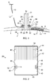
- Figure 1 shows part of a duct casing which includes a duct wall 2 comprising an intake section 4 and a containment casing 6.
- the intake section 4 is a twin-walled panel containing an acoustic filling (not shown) having a perforate skin on the gas-washed surface.
- Figure 1 shows part of an outer nacelle cowl skin 8.
- the skin 8 defines the nacelle outer cowl surface and extends to the front of the duct casing (to the left in Figure 1 ), and curves smoothly inwards relatively to the fan axis (which is not shown in Figure 1 but is situated below the Figure).
- the skin 8 is braced with respect to the intake section 4 by a partition 10 provided with an aperture 12 for passing systems.
- the containment casing 6 carries a honeycomb structure 14, which is covered by an abradable coating 16 across which fan blades, represented by a leading edge 18, sweep when the engine is operating.
- the intake section 4 is provided with a flange 20, and the containment casing 6 is provided with a flange 22.
- the flanges 20, 22 have oppositely disposed faces 24, 26, and an acoustic flutter damper 28 is positioned between these faces 24, 26.
- the flutter damper 28 projects into an acoustic cavity 32 defined between the intake section 4 and the containment casing 6.
- the cavity 32 may contain an acoustic liner structure.
- the radially inner end 30 itself terminates flush with the gas washed surfaces of the intake section 4 and the containment casing 6.
- the greater part of the radial extent of the acoustic flutter damper 28 projects radially outwardly of the flanges 20, 22. Because the acoustic flutter damper 28 is situated between the faces 24, 26 of the flanges 20, 22, the intake section 4 and the containment casing 6 are axially spaced apart from each other, rather than being directly connected together at the flanges 20, 22 as in known duct casings.
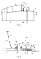
- FIG 2 is a sectional view of an acoustic flutter damper 28 of generally the same construction as that shown in Figure 1 , although of different proportions.
- the acoustic flutter damper 28 comprises a skin, of which only a part 34 is shown in Figure 2 .
- the skin part 34 extends over the radially outer end face of the acoustic flutter damper 28.
- the skin also comprises further parts 36 which extend over the axial end faces of the acoustic flutter damper 28 ( Figure 1 ), so that the skin comprises a continuous layer extending over the axial end faces and the radially outer face of the acoustic flutter damper 28.
- the interior of the skin 34, 36 accommodates an internal structure which comprises an assembly of interlocking welded or brazed panels made of thin sheet material.
- the internal structure comprises a first set of substantially identical panels 40, only one of which is visible in Figure 2 , and a further set of panels which extend perpendicular to the panels 40.
- each of the panels 40 is provided with a series of thin cuts 42 (see Figure 2 ) extending from the radially outer end of the panel.
- the other set of panels is provided with similar cuts extending from the radially inner edge, and the panels are interlocked by engaging the respective cuts of the two sets of panels so that the radially inner and outer edges of the panels lie in substantially the same plane, somewhat in the manner of a bottle divider in a case of wine.
- Other internal structures are possible, such as spot welded and expanded honeycomb structures.
- the interlocking panels form radially-extending passages 44 which are closed at their radially outer ends by the skin part 34, and which communicate with the duct defined by the duct wall 2 through a perforated panel 46.
- the panels 40 are formed at their axial edges with tabs 48 which are received in openings in the parts of the skin 34, 36 on the axial end faces 36 of the acoustic flutter damper 28, where they are plug-welded so that the panels 40 are connected between the skin parts 36.
- reinforcing ribs 50 are fixed to the inside surfaces of the axially directed skin parts 36, which are provided with tapped bores 52.
- Figure 1 shows an alternative construction in which, instead of the ribs 50 and tapped bores 52, the acoustic flutter damper 28 is provided with flanges 54 which are secured to the outer surfaces of the axial skin parts 36 by relatively slender webs 56.
- the flanges 54 are clamped to the flanges 20, 22 of the intake section 4 and the containment casing 6 by fasteners 58 in the form of bolts.
- the acoustic flutter damper 28 is secured between the flanges 20, 22 by bolts similar to the bolts 58, engaging the tapped bores 52.
- the axially facing skin parts 36 are in direct contact with the flanges 20, 22, and the acoustic flutter damper 28 occupies the entire axial space between these flanges.
- the fan blades 18 rotate within the duct defined by the duct wall 2, with the tips of the fan blades 18 sweeping across the abradable coating 16. Acoustic noise at audible wavelengths generated by the fan is absorbed in the filling of the intake section 4 and the acoustic cavity 32. If incipient flutter develops, the fluttering blades 18 generate low frequency pressure waves which are propagated forwards, ie to the left in Figure 1 , and enter the passages 44 of the acoustic flutter damper 28 through the perforated panel 46. The pressure waves thus travel up the individual passages 44 which are tuned, by adjustment of their length, in accordance with the expected frequency of the vibration experienced at the blades 18.
- Acoustic flutter dampers of the kind shown in the Figures are referred to as "deep liners" by virtue of the substantial length of the passages 44, by comparison with the shorter passages in the acoustic liner 4 and the cavity 32, which are accommodated in the relatively shallow space between the inner and outer skins of the intake section 4 and the front of the containment casing 6.
- axial loading between the intake section 4 and the containment casing 6 is transmitted through the acoustic flutter damper 28.
- Such loading may arise, for example, on start-up of the engine, when aerodynamic effects apply a load on the intake section 4 to the left as seen in Figure 1 , tending to draw the intake section 4 away from the containment casing 6.
- a fan blade 18, or a fragment of such a blade becomes detached from the rotor, it will be impelled outwardly under centrifugal force and will pass through the abradable lining 16 into the honeycomb structure 14. Since an ejected blade or fragment will have a significant component of momentum in the circumferential direction, it will travel around the containment casing 6, generating a circumferential deflection wave of significant amplitude. In other words, the containment casing 6 is deflected radially outwardly to a substantial extent, and the flange 22 will be locally deflected relatively to the flange 20. Such an event may cause the flange 22 to be displaced axially relatively to the flange 20 with sufficient force to fracture at least some of the panels 40. This will avoid the application of the full axial loading on the bolts 58, which will remain intact.
- the outer skin parts 34, 36 of the acoustic flutter damper 28 provide an alternative load path between the intake section 4 and the containment casing 6 following rupture of the internal structure (in particular, the panels 40). Consequently, the intake section 4 and the containment casing 6 remain connected together enabling the intake section 4 to be supported from the engine casing during engine run down.
- the acoustic flutter damper 28 can be constructed so that it will maintain its integrity under all normal operating conditions of the engine, but will fail in an FBO event, nevertheless providing an alternative load path around the skin 34, 36.
- the internal structure of the acoustic flutter damper 28 may be assembled from panels having a thickness of 0.5 mm, while the skin 34, 36 is constructed from material having a thickness of 2 mm.
- the acoustic flutter damper 28 may comprise a single circumferential unit, or an assembly made from two or more segments.
- the acoustic flutter damper 28 may be constructed as a cylindrical array of segments, for example 50 such segments, which are independently secured between the intake section 4 and the containment casing 6 by respective pairs of bolts 58.
- Figure 4 shows an alternative configuration to that shown in Figure 1 .
- the acoustic flutter damper 28 is bent along its length so that it has a first section 60 which opens into the gas flow path at a perforated panel 46, and a second section 62 which extends generally axially.
- Such a construction reduces the radial dimension of the acoustic flutter damper 28, for example to avoid interference with ducts or other components passing through the opening 12 in the partition 10.
- the acoustic flutter damper 28 can be installed without increasing the overall engine casing length beyond that of an engine lacking the acoustic flutter damper 28.
- the flange 22 of the containment casing 6 is provided on a flexible web so as to be situated directly adjacent the flange 20 on the intake section 4, the flexible web permitting a certain degree of relative radial displacement between the body of the containment casing 6 and the intake duct 4.
- the bend between the section 60 and 62 of the acoustic flutter damper 28 is expected to have a minimal impact on the acoustic performance of the acoustic flutter damper 28. Furthermore, the bend enhances the radial flexibility of the load path around the skin 34, 36 to minimise the transfer of FBO loads and deflections from the containment casing 6 to the intake section 4.
- the structure shown in Figure 4 also provides an enhanced axial load bearing capacity over that shown in Figure 1 .
- Figure 5 shows a further variant, in which the containment casing 6 provides part of the outer wall of the acoustic flutter damper 28.
- the skin 34, 36 has a first part 34 at the axial end of the passages 42 away from the intake of the acoustic flutter damper 28 at the perforated panel 46.
- the skin 34, 36 has a second part 36 which extends circumferentially around the duct wall 2.
- the acoustic flutter damper 28 has a forward end section 64 which provides a cavity 66 for accommodating the ends of the bolts 58.
- the cavity 66 is separated from the gas flow path by a block 68 of acoustic damping material.
- the perforations in the wall 70 are relatively large by comparison with the perforations in the perforated sheet 46.
- the perforate wall 70 may be an integral extension of the containment casing 6.
- the perforate wall 70 is designed to fuse under FBO.
- the skin 34, 36 provides a load path 72, indicated diagrammatically by a chain-dotted line in Figure 5 , which transfers load via a rearwardly directed extension 74 of the containment casing 6, over the skin 34, 36 to the flange 20 on the intake section 4.
- a load path 72 indicated diagrammatically by a chain-dotted line in Figure 5
- substantial radial displacement of the containment casing 6 relatively to the intake section 4 is accompanied by radial deflection of the axially extending skin part 36 preventing the transmission of loads to the intake part 4.
- axial loads are transmitted through the internal structure 40 of the acoustic flutter damper 28.
- a surface 76 of the containment casing 6 provides one wall of the acoustic flutter damper 28.
- Figure 6 shows another variant of the duct wall.
- the embodiment shown in Figure 6 is similar to that of Figure 5 , although the acoustic flutter damper 28 is provided with a generally axially extending skin part 36 on each side of the internal structure, which may again comprise interlocked panels in the manner described.
- the containment casing 6 provides a radial extension 78 which increased containment casing stiffness, and encloses the rearward end of the acoustic flutter damper 28 so that the end skin part 34 of the embodiment of Figure 5 is omitted.
- the load path 72 extends from the intake section flange 20 only to the rearward end of the skin 36.
- the embodiment of Figure 6 provides a reduced weight of the containment casing 6 compared with that of Figure 5 , since the acoustic flutter damper 28 does not need to be supported along its entire length by the surface 76. Instead, the containment casing 6 has a relatively slender extension 80 which supports part of the radially inner region of the skin 36 and a fan blade hook 82.
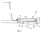
- Figure 7 shows an alternative variant, in which the containment casing 6 has a slender extension 84 which extends from the radial flange 78 to the fan blade hook 82, supporting the radially inner region of the skin 36 over substantially its entire length.
- the extension 84 is extended beyond the blade hook 82 as the perforated wall 70.
- the embodiment of Figure 7 provides additional space 86 for receiving a detached "windmilling" blade 18. Also, the additional space 86 provides additional capacity for blade capture and acoustic damping.
- the space may be filled with an acoustic material, for example of honeycomb form, which is crushed by a detached blade or blade fragment so as to absorb energy from the blade or blade fragment and to provide safe containment of debris.
- the present invention thus provides an acoustic flutter damper structure which is capable of withstanding normal loads between the intake section 4 and the containment casing 6, yet can deform, owing to the flexible skin 34, 36, in the event of major radial deflections of the containment casing 6 under an FBO event.
- the positioning of the acoustic flutter damper 28 at the junction between the intake section 4 and the containment case 6 provides good acoustic damping performance, owing to the proximity of its intake at the perforated panel 46 to the blades 18.
- the skin 34, 36 is made of relatively thin material, in order to provide the required flexibility, and consequently represents a weight saving over traditional designs with benefits to the intake design load cases.
- the structure of the acoustic flutter damper 28 also provides a mechanism for module separation for ease of maintenance.
- some components of the acoustic flutter damper 28, for example the internal structure 40, can be incorporated as part of the structure of the containment casing 6, so reducing the part count and weight of the assembly.
- the flexible skin 34, 36 can provide a load path 72 which is adjustable by modifying the design of the acoustic flutter damper 28, for example to provide a bend between the section 60 and 62 in the embodiment of Figure 4 .
- the flexibility of the skin 34, 36, and the consequent reduction in FBO loads transmitted from the containment casing 6 to the intake section 4 means that the bulk of the flanges 20, 22 can be reduced and yet withstand a given deflection of the containment casing 6.
- the intake structure can be designed to benefit from the reduction in transmitted loads. Alternatively, existing flange designs can tolerate greater deflections of the containment casing 6.
- the acoustic flutter damper 28 can withstand loads imposed during normal operation, so maintaining the relative positioning of the intake section 4 and the containment casing 6. Under FBO loads, the initial load path will fail, so that support between the intake section 4 and the containment casing 6 is transferred to the flexible skin 34, 36 of the acoustic flutter damper 28.
- acoustic flutter damper 28 By positioning the acoustic flutter damper 28 radially outboard of the containment casing 6 avoids increasing the overall length of the fan casing without requiring a reduction in the length of the acoustic layer 14.
- the acoustic damping effect of the acoustic flutter damper 28 can make it possible to avoid incorporating an acoustic liner in the intake section 4, ahead of the junction between the intake panel 4 and the containment casing 6.
- the radial flange 78 enhances the rigidity of the containment casing 6, so making it possible to avoid separate stiffening ribs such as those indicated at 86 in Figure 4 .
- the present invention by reducing the loads applied to the bolts 58 in an FBO event, make it possible to avoid other measures for relieving stress on these bolts, for example by means of collapsible collars. Furthermore, the crushing or rupturing of the internal structure 40 of the acoustic flutter damper 28 provides an effective mechanism for absorbing the energy released during an FBO event.
Landscapes
- Engineering & Computer Science (AREA)
- Mechanical Engineering (AREA)
- General Engineering & Computer Science (AREA)
- Structures Of Non-Positive Displacement Pumps (AREA)
Applications Claiming Priority (1)
| Application Number | Priority Date | Filing Date | Title |
|---|---|---|---|
| GBGB0907582.1A GB0907582D0 (en) | 2009-05-05 | 2009-05-05 | A duct wall for a fan of a gas turbine engine |
Publications (2)
| Publication Number | Publication Date |
|---|---|
| EP2273076A1 true EP2273076A1 (de) | 2011-01-12 |
| EP2273076B1 EP2273076B1 (de) | 2012-02-29 |
Family
ID=40792161
Family Applications (1)
| Application Number | Title | Priority Date | Filing Date |
|---|---|---|---|
| EP10161137A Ceased EP2273076B1 (de) | 2009-05-05 | 2010-04-27 | Kanalwand für ein Gebläse eines Gasturbinenmotors |
Country Status (4)
| Country | Link |
|---|---|
| US (1) | US8434995B2 (de) |
| EP (1) | EP2273076B1 (de) |
| AT (1) | ATE547593T1 (de) |
| GB (1) | GB0907582D0 (de) |
Families Citing this family (17)
| Publication number | Priority date | Publication date | Assignee | Title |
|---|---|---|---|---|
| GB2459646B (en) * | 2008-04-28 | 2011-03-30 | Rolls Royce Plc | A fan assembly |
| GB201021265D0 (en) * | 2010-12-15 | 2011-01-26 | Rolls Royce Plc | An acoustic liner |
| US9514734B1 (en) * | 2011-06-30 | 2016-12-06 | The United States Of America As Represented By The Administrator Of National Aeronautics And Space Administration | Acoustic liners for turbine engines |
| GB201209658D0 (en) * | 2012-05-31 | 2012-07-11 | Rolls Royce Plc | Acoustic panel |
| US9194251B2 (en) | 2012-08-10 | 2015-11-24 | United Technologies Corporation | Duct damper |
| FR2995038B1 (fr) * | 2012-08-30 | 2014-09-19 | Snecma | Carter de soufflante de turbine a gaz ayant une ceinture de fixation d'equipements |
| US10669936B2 (en) * | 2013-03-13 | 2020-06-02 | Raytheon Technologies Corporation | Thermally conforming acoustic liner cartridge for a gas turbine engine |
| DE102014218350A1 (de) * | 2014-09-12 | 2016-03-17 | Rolls-Royce Deutschland Ltd & Co Kg | Schalldämpfende Anordnung für eine Triebwerksgondel und Triebwerksgondel mit einer solchen Anordnung |
| US10619566B2 (en) | 2017-03-07 | 2020-04-14 | United Technologies Corporation | Flutter damper for a turbofan engine |
| US10941708B2 (en) | 2017-03-07 | 2021-03-09 | Raytheon Technologies Corporation | Acoustically damped gas turbine engine |
| US10539156B2 (en) | 2017-03-07 | 2020-01-21 | United Technologies Corporation | Variable displacement flutter damper for a turbofan engine |
| US10422280B2 (en) * | 2017-03-07 | 2019-09-24 | United Technologies Corporation | Fan flutter suppression system |
| US10415506B2 (en) | 2017-03-07 | 2019-09-17 | United Technologies Corporation | Multi degree of freedom flutter damper |
| US10612464B2 (en) | 2017-03-07 | 2020-04-07 | United Technologies Corporation | Flutter inhibiting intake for gas turbine propulsion system |
| US10428685B2 (en) | 2017-03-07 | 2019-10-01 | United Technologies Corporation | Flutter inhibiting intake for gas turbine propulsion system |
| US10550718B2 (en) | 2017-03-31 | 2020-02-04 | The Boeing Company | Gas turbine engine fan blade containment systems |
| US10487684B2 (en) | 2017-03-31 | 2019-11-26 | The Boeing Company | Gas turbine engine fan blade containment systems |
Citations (3)
| Publication number | Priority date | Publication date | Assignee | Title |
|---|---|---|---|---|
| GB2090334A (en) | 1980-12-29 | 1982-07-07 | Rolls Royce | Damping flutter of ducted fans |
| GB2365945A (en) * | 2000-08-16 | 2002-02-27 | Rolls Royce Plc | A vibration damping system |
| EP1596037A2 (de) * | 2004-05-13 | 2005-11-16 | ROLLS-ROYCE plc | Schaufelanordnung |
Family Cites Families (13)
| Publication number | Priority date | Publication date | Assignee | Title |
|---|---|---|---|---|
| FR2470269A1 (fr) | 1979-11-27 | 1981-05-29 | Snecma | Structure de retention pour carter de compresseur d'une turbomachine |
| US4934899A (en) * | 1981-12-21 | 1990-06-19 | United Technologies Corporation | Method for containing particles in a rotary machine |
| US4484856A (en) * | 1981-12-21 | 1984-11-27 | United Technologies Corporation | Containment structure |
| US4718818A (en) * | 1981-12-21 | 1988-01-12 | United Technologies Corporation | Containment structure |
| US5267828A (en) * | 1992-11-13 | 1993-12-07 | General Electric Company | Removable fan shroud panel |
| GB0107973D0 (en) * | 2001-03-30 | 2001-05-23 | Rolls Royce Plc | A gas turbine engine blade containment assembly |
| DE10228103A1 (de) | 2002-06-24 | 2004-01-15 | Bayer Cropscience Ag | Fungizide Wirkstoffkombinationen |
| US6652222B1 (en) | 2002-09-03 | 2003-11-25 | Pratt & Whitney Canada Corp. | Fan case design with metal foam between Kevlar |
| GB2407344B (en) * | 2003-10-22 | 2006-02-22 | Rolls Royce Plc | A liner for a gas turbine engine casing |
| FR2868123B1 (fr) * | 2004-03-29 | 2006-06-23 | Airbus France Sas | Structure d'entree d'air pour moteur d'aeronef |
| GB2427436B (en) * | 2005-06-23 | 2007-11-28 | Rolls Royce Plc | Fan duct blade containment assembly |
| US7753643B2 (en) * | 2006-09-22 | 2010-07-13 | Siemens Energy, Inc. | Stacked laminate bolted ring segment |
| FR2926789B1 (fr) | 2008-01-29 | 2010-05-28 | Aircelle Sa | Nacelle pour turboreacteur |
-
2009
- 2009-05-05 GB GBGB0907582.1A patent/GB0907582D0/en not_active Ceased
-
2010
- 2010-04-27 AT AT10161137T patent/ATE547593T1/de active
- 2010-04-27 US US12/768,316 patent/US8434995B2/en not_active Expired - Fee Related
- 2010-04-27 EP EP10161137A patent/EP2273076B1/de not_active Ceased
Patent Citations (3)
| Publication number | Priority date | Publication date | Assignee | Title |
|---|---|---|---|---|
| GB2090334A (en) | 1980-12-29 | 1982-07-07 | Rolls Royce | Damping flutter of ducted fans |
| GB2365945A (en) * | 2000-08-16 | 2002-02-27 | Rolls Royce Plc | A vibration damping system |
| EP1596037A2 (de) * | 2004-05-13 | 2005-11-16 | ROLLS-ROYCE plc | Schaufelanordnung |
Also Published As
| Publication number | Publication date |
|---|---|
| US8434995B2 (en) | 2013-05-07 |
| US20100284790A1 (en) | 2010-11-11 |
| ATE547593T1 (de) | 2012-03-15 |
| GB0907582D0 (en) | 2009-06-10 |
| EP2273076B1 (de) | 2012-02-29 |
Similar Documents
| Publication | Publication Date | Title |
|---|---|---|
| EP2273076B1 (de) | Kanalwand für ein Gebläse eines Gasturbinenmotors | |
| JP5425908B2 (ja) | タービンエンジンのナセルの内壁 | |
| EP2256302B1 (de) | Kanalwand für ein Gebläse eines Gasturbinenmotors | |
| US6179551B1 (en) | Gas turbine containment casing | |
| US8438857B2 (en) | Aircraft engine inlet having zone of deformation | |
| US8926263B2 (en) | Turbomachine casing assembly | |
| US5823739A (en) | Containment case for a turbine engine | |
| US9169045B2 (en) | Gas turbine engine blade containment arrangement | |
| US4531362A (en) | Aerodynamic damping of vibrations in rotor blades | |
| EP2333251A2 (de) | Fan-Berstschutzring | |
| EP1083300B1 (de) | Bläsergehäuse mit doppelwandiger Berstschutzstruktur | |
| EP1245791B1 (de) | Berstschutzvorrichtung für eine Gasturbine | |
| US9683490B2 (en) | Pivoting fan track liner for blade retainment | |
| US6394746B1 (en) | Gas turbine engine blade containment assembly | |
| EP2876262B1 (de) | Fan-Rückhaltesystem für ein axiales Gasturbinentriebwerk | |
| JPH0350108B2 (de) | ||
| US9677417B2 (en) | Gas turbine engine | |
| US7806364B1 (en) | Containment system for a gas turbine engine | |
| US7445421B2 (en) | Fan duct blade containment assembly |
Legal Events
| Date | Code | Title | Description |
|---|---|---|---|
| PUAI | Public reference made under article 153(3) epc to a published international application that has entered the european phase |
Free format text: ORIGINAL CODE: 0009012 |
|
| AK | Designated contracting states |
Kind code of ref document: A1 Designated state(s): AT BE BG CH CY CZ DE DK EE ES FI FR GB GR HR HU IE IS IT LI LT LU LV MC MK MT NL NO PL PT RO SE SI SK SM TR |
|
| AX | Request for extension of the european patent |
Extension state: AL BA ME RS |
|
| 17P | Request for examination filed |
Effective date: 20110310 |
|
| GRAP | Despatch of communication of intention to grant a patent |
Free format text: ORIGINAL CODE: EPIDOSNIGR1 |
|
| RIC1 | Information provided on ipc code assigned before grant |
Ipc: F01D 21/04 20060101AFI20111031BHEP Ipc: F01D 5/16 20060101ALI20111031BHEP Ipc: F01D 25/06 20060101ALI20111031BHEP |
|
| GRAS | Grant fee paid |
Free format text: ORIGINAL CODE: EPIDOSNIGR3 |
|
| GRAA | (expected) grant |
Free format text: ORIGINAL CODE: 0009210 |
|
| AK | Designated contracting states |
Kind code of ref document: B1 Designated state(s): AT BE BG CH CY CZ DE DK EE ES FI FR GB GR HR HU IE IS IT LI LT LU LV MC MK MT NL NO PL PT RO SE SI SK SM TR |
|
| REG | Reference to a national code |
Ref country code: GB Ref legal event code: FG4D Ref country code: CH Ref legal event code: EP |
|
| REG | Reference to a national code |
Ref country code: AT Ref legal event code: REF Ref document number: 547593 Country of ref document: AT Kind code of ref document: T Effective date: 20120315 |
|
| REG | Reference to a national code |
Ref country code: IE Ref legal event code: FG4D |
|
| REG | Reference to a national code |
Ref country code: DE Ref legal event code: R096 Ref document number: 602010000909 Country of ref document: DE Effective date: 20120426 |
|
| REG | Reference to a national code |
Ref country code: NL Ref legal event code: VDEP Effective date: 20120229 |
|
| LTIE | Lt: invalidation of european patent or patent extension |
Effective date: 20120229 |
|
| PG25 | Lapsed in a contracting state [announced via postgrant information from national office to epo] |
Ref country code: NO Free format text: LAPSE BECAUSE OF FAILURE TO SUBMIT A TRANSLATION OF THE DESCRIPTION OR TO PAY THE FEE WITHIN THE PRESCRIBED TIME-LIMIT Effective date: 20120529 Ref country code: IS Free format text: LAPSE BECAUSE OF FAILURE TO SUBMIT A TRANSLATION OF THE DESCRIPTION OR TO PAY THE FEE WITHIN THE PRESCRIBED TIME-LIMIT Effective date: 20120629 Ref country code: LT Free format text: LAPSE BECAUSE OF FAILURE TO SUBMIT A TRANSLATION OF THE DESCRIPTION OR TO PAY THE FEE WITHIN THE PRESCRIBED TIME-LIMIT Effective date: 20120229 Ref country code: NL Free format text: LAPSE BECAUSE OF FAILURE TO SUBMIT A TRANSLATION OF THE DESCRIPTION OR TO PAY THE FEE WITHIN THE PRESCRIBED TIME-LIMIT Effective date: 20120229 Ref country code: HR Free format text: LAPSE BECAUSE OF FAILURE TO SUBMIT A TRANSLATION OF THE DESCRIPTION OR TO PAY THE FEE WITHIN THE PRESCRIBED TIME-LIMIT Effective date: 20120229 |
|
| PG25 | Lapsed in a contracting state [announced via postgrant information from national office to epo] |
Ref country code: PT Free format text: LAPSE BECAUSE OF FAILURE TO SUBMIT A TRANSLATION OF THE DESCRIPTION OR TO PAY THE FEE WITHIN THE PRESCRIBED TIME-LIMIT Effective date: 20120629 Ref country code: BE Free format text: LAPSE BECAUSE OF FAILURE TO SUBMIT A TRANSLATION OF THE DESCRIPTION OR TO PAY THE FEE WITHIN THE PRESCRIBED TIME-LIMIT Effective date: 20120229 Ref country code: LV Free format text: LAPSE BECAUSE OF FAILURE TO SUBMIT A TRANSLATION OF THE DESCRIPTION OR TO PAY THE FEE WITHIN THE PRESCRIBED TIME-LIMIT Effective date: 20120229 Ref country code: FI Free format text: LAPSE BECAUSE OF FAILURE TO SUBMIT A TRANSLATION OF THE DESCRIPTION OR TO PAY THE FEE WITHIN THE PRESCRIBED TIME-LIMIT Effective date: 20120229 Ref country code: GR Free format text: LAPSE BECAUSE OF FAILURE TO SUBMIT A TRANSLATION OF THE DESCRIPTION OR TO PAY THE FEE WITHIN THE PRESCRIBED TIME-LIMIT Effective date: 20120530 |
|
| REG | Reference to a national code |
Ref country code: AT Ref legal event code: MK05 Ref document number: 547593 Country of ref document: AT Kind code of ref document: T Effective date: 20120229 |
|
| PG25 | Lapsed in a contracting state [announced via postgrant information from national office to epo] |
Ref country code: CY Free format text: LAPSE BECAUSE OF FAILURE TO SUBMIT A TRANSLATION OF THE DESCRIPTION OR TO PAY THE FEE WITHIN THE PRESCRIBED TIME-LIMIT Effective date: 20120229 |
|
| PG25 | Lapsed in a contracting state [announced via postgrant information from national office to epo] |
Ref country code: CZ Free format text: LAPSE BECAUSE OF FAILURE TO SUBMIT A TRANSLATION OF THE DESCRIPTION OR TO PAY THE FEE WITHIN THE PRESCRIBED TIME-LIMIT Effective date: 20120229 Ref country code: DK Free format text: LAPSE BECAUSE OF FAILURE TO SUBMIT A TRANSLATION OF THE DESCRIPTION OR TO PAY THE FEE WITHIN THE PRESCRIBED TIME-LIMIT Effective date: 20120229 Ref country code: PL Free format text: LAPSE BECAUSE OF FAILURE TO SUBMIT A TRANSLATION OF THE DESCRIPTION OR TO PAY THE FEE WITHIN THE PRESCRIBED TIME-LIMIT Effective date: 20120229 Ref country code: SE Free format text: LAPSE BECAUSE OF FAILURE TO SUBMIT A TRANSLATION OF THE DESCRIPTION OR TO PAY THE FEE WITHIN THE PRESCRIBED TIME-LIMIT Effective date: 20120229 Ref country code: RO Free format text: LAPSE BECAUSE OF FAILURE TO SUBMIT A TRANSLATION OF THE DESCRIPTION OR TO PAY THE FEE WITHIN THE PRESCRIBED TIME-LIMIT Effective date: 20120229 Ref country code: EE Free format text: LAPSE BECAUSE OF FAILURE TO SUBMIT A TRANSLATION OF THE DESCRIPTION OR TO PAY THE FEE WITHIN THE PRESCRIBED TIME-LIMIT Effective date: 20120229 Ref country code: SI Free format text: LAPSE BECAUSE OF FAILURE TO SUBMIT A TRANSLATION OF THE DESCRIPTION OR TO PAY THE FEE WITHIN THE PRESCRIBED TIME-LIMIT Effective date: 20120229 |
|
| PG25 | Lapsed in a contracting state [announced via postgrant information from national office to epo] |
Ref country code: SK Free format text: LAPSE BECAUSE OF FAILURE TO SUBMIT A TRANSLATION OF THE DESCRIPTION OR TO PAY THE FEE WITHIN THE PRESCRIBED TIME-LIMIT Effective date: 20120229 Ref country code: IT Free format text: LAPSE BECAUSE OF FAILURE TO SUBMIT A TRANSLATION OF THE DESCRIPTION OR TO PAY THE FEE WITHIN THE PRESCRIBED TIME-LIMIT Effective date: 20120229 Ref country code: MC Free format text: LAPSE BECAUSE OF NON-PAYMENT OF DUE FEES Effective date: 20120430 |
|
| PLBE | No opposition filed within time limit |
Free format text: ORIGINAL CODE: 0009261 |
|
| STAA | Information on the status of an ep patent application or granted ep patent |
Free format text: STATUS: NO OPPOSITION FILED WITHIN TIME LIMIT |
|
| PG25 | Lapsed in a contracting state [announced via postgrant information from national office to epo] |
Ref country code: AT Free format text: LAPSE BECAUSE OF FAILURE TO SUBMIT A TRANSLATION OF THE DESCRIPTION OR TO PAY THE FEE WITHIN THE PRESCRIBED TIME-LIMIT Effective date: 20120229 |
|
| 26N | No opposition filed |
Effective date: 20121130 |
|
| PG25 | Lapsed in a contracting state [announced via postgrant information from national office to epo] |
Ref country code: MK Free format text: LAPSE BECAUSE OF FAILURE TO SUBMIT A TRANSLATION OF THE DESCRIPTION OR TO PAY THE FEE WITHIN THE PRESCRIBED TIME-LIMIT Effective date: 20120229 |
|
| REG | Reference to a national code |
Ref country code: DE Ref legal event code: R097 Ref document number: 602010000909 Country of ref document: DE Effective date: 20121130 |
|
| PG25 | Lapsed in a contracting state [announced via postgrant information from national office to epo] |
Ref country code: IE Free format text: LAPSE BECAUSE OF NON-PAYMENT OF DUE FEES Effective date: 20120427 Ref country code: ES Free format text: LAPSE BECAUSE OF FAILURE TO SUBMIT A TRANSLATION OF THE DESCRIPTION OR TO PAY THE FEE WITHIN THE PRESCRIBED TIME-LIMIT Effective date: 20120609 |
|
| PG25 | Lapsed in a contracting state [announced via postgrant information from national office to epo] |
Ref country code: MT Free format text: LAPSE BECAUSE OF FAILURE TO SUBMIT A TRANSLATION OF THE DESCRIPTION OR TO PAY THE FEE WITHIN THE PRESCRIBED TIME-LIMIT Effective date: 20120229 Ref country code: BG Free format text: LAPSE BECAUSE OF FAILURE TO SUBMIT A TRANSLATION OF THE DESCRIPTION OR TO PAY THE FEE WITHIN THE PRESCRIBED TIME-LIMIT Effective date: 20120529 |
|
| PG25 | Lapsed in a contracting state [announced via postgrant information from national office to epo] |
Ref country code: TR Free format text: LAPSE BECAUSE OF FAILURE TO SUBMIT A TRANSLATION OF THE DESCRIPTION OR TO PAY THE FEE WITHIN THE PRESCRIBED TIME-LIMIT Effective date: 20120229 |
|
| PG25 | Lapsed in a contracting state [announced via postgrant information from national office to epo] |
Ref country code: SM Free format text: LAPSE BECAUSE OF FAILURE TO SUBMIT A TRANSLATION OF THE DESCRIPTION OR TO PAY THE FEE WITHIN THE PRESCRIBED TIME-LIMIT Effective date: 20120229 Ref country code: LU Free format text: LAPSE BECAUSE OF NON-PAYMENT OF DUE FEES Effective date: 20120427 |
|
| PG25 | Lapsed in a contracting state [announced via postgrant information from national office to epo] |
Ref country code: HU Free format text: LAPSE BECAUSE OF FAILURE TO SUBMIT A TRANSLATION OF THE DESCRIPTION OR TO PAY THE FEE WITHIN THE PRESCRIBED TIME-LIMIT Effective date: 20100427 |
|
| REG | Reference to a national code |
Ref country code: CH Ref legal event code: PL |
|
| PG25 | Lapsed in a contracting state [announced via postgrant information from national office to epo] |
Ref country code: LI Free format text: LAPSE BECAUSE OF NON-PAYMENT OF DUE FEES Effective date: 20140430 Ref country code: CH Free format text: LAPSE BECAUSE OF NON-PAYMENT OF DUE FEES Effective date: 20140430 |
|
| REG | Reference to a national code |
Ref country code: FR Ref legal event code: PLFP Year of fee payment: 6 |
|
| REG | Reference to a national code |
Ref country code: FR Ref legal event code: PLFP Year of fee payment: 7 |
|
| REG | Reference to a national code |
Ref country code: FR Ref legal event code: PLFP Year of fee payment: 8 |
|
| REG | Reference to a national code |
Ref country code: FR Ref legal event code: PLFP Year of fee payment: 9 |
|
| PGFP | Annual fee paid to national office [announced via postgrant information from national office to epo] |
Ref country code: FR Payment date: 20200429 Year of fee payment: 11 |
|
| PGFP | Annual fee paid to national office [announced via postgrant information from national office to epo] |
Ref country code: GB Payment date: 20200429 Year of fee payment: 11 |
|
| PGFP | Annual fee paid to national office [announced via postgrant information from national office to epo] |
Ref country code: DE Payment date: 20200629 Year of fee payment: 11 |
|
| REG | Reference to a national code |
Ref country code: DE Ref legal event code: R119 Ref document number: 602010000909 Country of ref document: DE |
|
| GBPC | Gb: european patent ceased through non-payment of renewal fee |
Effective date: 20210427 |
|
| PG25 | Lapsed in a contracting state [announced via postgrant information from national office to epo] |
Ref country code: DE Free format text: LAPSE BECAUSE OF NON-PAYMENT OF DUE FEES Effective date: 20211103 Ref country code: FR Free format text: LAPSE BECAUSE OF NON-PAYMENT OF DUE FEES Effective date: 20210430 Ref country code: GB Free format text: LAPSE BECAUSE OF NON-PAYMENT OF DUE FEES Effective date: 20210427 |