EP2273128A1 - Pompe à vide - Google Patents
Pompe à vide Download PDFInfo
- Publication number
- EP2273128A1 EP2273128A1 EP10175459A EP10175459A EP2273128A1 EP 2273128 A1 EP2273128 A1 EP 2273128A1 EP 10175459 A EP10175459 A EP 10175459A EP 10175459 A EP10175459 A EP 10175459A EP 2273128 A1 EP2273128 A1 EP 2273128A1
- Authority
- EP
- European Patent Office
- Prior art keywords
- cartridge
- housing
- pump
- mass spectrometer
- pumping
- Prior art date
- Legal status (The legal status is an assumption and is not a legal conclusion. Google has not performed a legal analysis and makes no representation as to the accuracy of the status listed.)
- Granted
Links
Images



Classifications
-
- F—MECHANICAL ENGINEERING; LIGHTING; HEATING; WEAPONS; BLASTING
- F04—POSITIVE - DISPLACEMENT MACHINES FOR LIQUIDS; PUMPS FOR LIQUIDS OR ELASTIC FLUIDS
- F04D—NON-POSITIVE-DISPLACEMENT PUMPS
- F04D29/00—Details, component parts, or accessories
- F04D29/60—Mounting; Assembling; Disassembling
- F04D29/601—Mounting; Assembling; Disassembling specially adapted for elastic fluid pumps
-
- F—MECHANICAL ENGINEERING; LIGHTING; HEATING; WEAPONS; BLASTING
- F04—POSITIVE - DISPLACEMENT MACHINES FOR LIQUIDS; PUMPS FOR LIQUIDS OR ELASTIC FLUIDS
- F04D—NON-POSITIVE-DISPLACEMENT PUMPS
- F04D19/00—Axial-flow pumps
- F04D19/02—Multi-stage pumps
- F04D19/04—Multi-stage pumps specially adapted to the production of a high vacuum, e.g. molecular pumps
- F04D19/042—Turbomolecular vacuum pumps
-
- G—PHYSICS
- G01—MEASURING; TESTING
- G01M—TESTING STATIC OR DYNAMIC BALANCE OF MACHINES OR STRUCTURES; TESTING OF STRUCTURES OR APPARATUS, NOT OTHERWISE PROVIDED FOR
- G01M3/00—Investigating fluid-tightness of structures
- G01M3/02—Investigating fluid-tightness of structures by using fluid or vacuum
- G01M3/04—Investigating fluid-tightness of structures by using fluid or vacuum by detecting the presence of fluid at the leakage point
- G01M3/20—Investigating fluid-tightness of structures by using fluid or vacuum by detecting the presence of fluid at the leakage point using special tracer materials, e.g. dye, fluorescent material, radioactive material
- G01M3/202—Investigating fluid-tightness of structures by using fluid or vacuum by detecting the presence of fluid at the leakage point using special tracer materials, e.g. dye, fluorescent material, radioactive material using mass spectrometer detection systems
- G01M3/205—Accessories or associated equipment; Pump constructions
-
- H—ELECTRICITY
- H01—ELECTRIC ELEMENTS
- H01J—ELECTRIC DISCHARGE TUBES OR DISCHARGE LAMPS
- H01J49/00—Particle spectrometers or separator tubes
- H01J49/02—Details
- H01J49/24—Vacuum systems, e.g. maintaining desired pressures
Definitions
- This invention relates to a vacuum pump, and in particular to a vacuum pump with multiple inlets suitable for differential pumping of multiple chambers.
- the analyser / detector has to be operated at a relatively high vacuum, for example 10 -5 mbar, whereas a transfer chamber, through which ions drawn and guided from an ion source are conveyed towards the detector, is operated at a lower vacuum, for example 10 -3 mbar.
- the mass spectrometer may comprise one or more further chambers upstream from the analyser chamber, which are operated at progressively higher pressures to enable ions generated in an atmospheric source to be captured and eventually guided towards the detector.
- turbo-molecular vacuum pumps each backed by a separate, or common backing pump, for example a rotary vane pump
- a separate, or common backing pump for example a rotary vane pump
- a split flow turbo-molecular pump having a plurality of inlets each for receiving fluid from respective chamber, and a plurality of pumping stages for differentially evacuating the chambers.
- EP-A 0 919 726 describes a split flow pump comprising a plurality of vacuum stages and having a first pump inlet through which gas can pass through all the pump stages and a second inlet through which gas can enter the pump at an inter-stage location and pass only through a subsequent stage of the pump.
- the pump stages prior to the inter-stage location are sized differently from those stages subsequent to the inter-stage location to meet the pressure requirements of the different chambers attached to the first and the second inlets respectively.
- the present invention provides a system comprising a plurality of pressure chambers and a vacuum pump for differentially evacuating the chambers, the pump comprising a plurality of inlets each for receiving fluid from a respective pressure chamber and a pumping mechanism for differentially pumping fluid from the chambers, wherein the pump protrudes through an opening into the chambers such that at least one of the fluid inlets is at least partially located within its respective pressure chamber, and the longitudinal axis of the pump is inclined to the plane of the mouth of the opening.
- the conductance of the inlets of the pump can be maximised and high effective pumping speeds can be achieved for a given pumping mechanism. Furthermore, since the pump protrudes into the chambers, the overall volume occupied by the chambers and pump is minimised.
- the present invention provides a differentially pumped mass spectrometer system comprising a mass spectrometer having a plurality of pressure chambers through which, during use, ions are conveyed along a path; and a pump for differentially evacuating the chambers, the pump comprising a plurality of inlets each for receiving fluid from a respective pressure chamber and a pumping mechanism for differentially pumping fluid from the chambers, wherein the pump is inclined relative to at least part of the ion path and protrudes into the spectrometer without crossing the ion path but with at least one, preferably each, of the fluid inlets at least partially located within its respective pressure chamber.
- the pump is preferably in the form of a cartridge inserted into a housing attached to or part of the mass spectrometer such that the cartridge protrudes through a mouth of the housing into said at least one of the chambers.
- This can provide a relatively simple construction for mounting and aligning the pump relative to the chambers under evacuation, as opposed to an arrangement wherein the pump is integrated into the body of the mass spectrometer.
- a third aspect of the present invention provides a pump comprising a housing, a cartridge insertable into the housing, the cartridge comprising a fluid inlet and a pumping mechanism, and means for locating the cartridge within the housing such that a part of the cartridge defining the fluid inlet protrudes from a mouth of the housing, and such that the longitudinal axis of the pumping mechanism is inclined relative to the plane of the mouth.
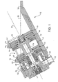
- the pump 10 comprises a housing 12 having a bore for receiving a cylindrical cartridge 14 containing a pumping mechanism and a plurality of fluid inlets 16, 18, 20 and a fluid outlet 22.
- the cartridge 14 comprises a multi-component body 24 within which is mounted a drive shaft 26. Rotation of the shaft 26 is effected by a motor 28 positioned about the shaft 26.
- the shaft 26 is mounted on opposite bearings.
- the drive shaft 26 may be supported by a hybrid permanent magnet bearing and oil lubricated bearing system.
- the pumping mechanism within the cartridge includes at least three pumping sections 30, 32, 34.
- the first pumping section 30 comprises a set of turbo-molecular stages.
- the set of turbo-molecular stages 30 comprises four rotor blades and four stator blades of known angled construction.
- the rotor blades of the first pumping section are integral with the drive shaft 26.
- the second pumping section 32 is similar to the first pumping section 30, and also comprises a set of turbo-molecular stages.
- the set of turbo-molecular stages 32 also comprises four rotor blades and four stator blades of known angled construction.
- the rotor blades of the first pumping section are also integral with the drive shaft 26.
- the third pumping section 34 is in the form of a molecular drag mechanism, for example, a Holweck drag mechanism.
- the Holweck mechanism comprises two rotating cylinders and corresponding annular stators having helical channels formed therein in a manner known per se.
- the rotating cylinders are preferably formed from a carbon fibre material, and are mounted on a disc located on the drive shaft 26. In this example, the disc is also integral with the drive shaft 26.
- the pump outlet 22 is located downstream from the Holweck mechanism 34.
- the cartridge 14 has three inlets 16, 18 and 20.
- the first, low fluid pressure inlet 16 is located upstream of all of the pumping sections. In this example, the first inlet 16 is substantially orthogonal to the longitudinal axis of the drive shaft 26, as indicated at 36.
- the second, middle fluid pressure inlet 18 is located interstage the first pumping section 30 and the second pumping section 32. In this example, the second inlet 18 extends about the longitudinal axis of the drive shaft 26.
- the third, low fluid pressure inlet 20 may be located, as illustrated, upstream of or, alternatively, between the stages of the Holweck mechanism 34, such that all of the stages of the Holweck mechanism are in fluid communication with the each of the inlets 16, 18,20.
- the bore has an inlet formed in the rear surface 38 of the housing 12 and through which the cartridge 14 is inserted into the housing 12.
- the inner surfaces 40, 42, 44, 46 of the bore guide the cartridge 14 towards the fully inserted position shown in Figures 1 to 6 as it is inserted into the bore.
- the end of the bore is profiled as indicated at 48 in Figure 1 to define abutment surfaces for engaging the front end of the inserted cartridge 14 and which, with the rear surface 38 of the housing 12, limit the extent to which the cartridge 14 can be inserted into the housing 12.
- the housing 12 is shaped so as to expose the bore at a number of locations to allow fluid to enter the fluid inlets 16, 18, 20 when the cartridge 14 is in the fully inserted position.
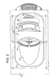
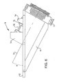
- the housing 12 comprises a mouth 50 formed in a flanged planar surface 52 of the housing 12, the flanged planar surface 52 being inclined at an acute angle to the rear surface 38 of the housing, and at an acute angle ⁇ to the longitudinal axis of the bore of the housing.
- the longitudinal axis 36 of the pumping mechanism is co-axial with the bore of the housing 12.
- curved members 54, 56 defining part of the bore of the housing 12 extend across the mouth 50 of the housing 12.
- the curved members 54, 56 are integral with the housing 12.
- the curved members 54, 56 may be separate members insertable into the housing 12.
- part of the first inlet 16 and part of the second inlet 18 project through the mouth 50 of the housing 12, whilst the third inlet 20 is located just beneath the mouth 50.
- Figure 7 shows the pump 10 attached to an example of a multi-chamber system 60 to be evacuated using the pump 10.
- the multi-chamber system 60 is a mass spectrometer system.
- a high vacuum chamber 62 immediately follows first, (depending on the type of system) second, and third evacuated interface chambers 64, 66, 68.
- the first interface chamber 64 is the highest-pressure chamber in the evacuated spectrometer system and may contain a capillary or sample cone through which ions are drawn from an ion source into the first interface chamber 64.
- the second, interface chamber 66 may include a first ion guide for guiding ions from the first interface chamber 64 into the third interface chamber 68
- the third chamber 68 may include a second ion guide for guiding ions from the second interface chamber into the high vacuum chamber 62.
- the flanged planar surface 52 of the pump 10 is attached to the planar, bottom surface 70 of the system 60, for example by means of bolts or the like.
- An O-ring located within a groove 72 assists in forming a seal between the surfaces 52 and 70.
- the cartridge 14 protrudes into the system 60 through an opening 74 formed in the bottom surface 70 of the system such that the first inlet 16 of the cartridge 14 and the first pumping section 30 protrude into the high vacuum chamber 62, and the second inlet 18 of the cartridge 14 and the second pumping section 32 protrude into the third chamber 68, and such that the pump 10 is inclined at angle ⁇ to the path 76 of ions conveyed within the system 60 during use to maximise conductance at the inlets of the pump.
- the extent to which the pump 10 extends into the system 60 is not so great, however, as to cause the pump to cross the ion path 76.
- the upper surface 78 of the cross member 54 sealingly engages a conformingly-profiled lower surface of the dividing wall 80 between the high vacuum chamber 60 and the third chamber 68
- the upper surface 82 of the cross member 56 sealingly engages a conformingly-profiled lower surface of the dividing wall 84 between the second chamber 66 and the third chamber 68.
- the first interface chamber 64 is connected to a backing pump (not shown), which also pumps fluid from the outlet 22 of the pump 10.
- the backing pump typically creates a pressure within the first chamber of roughly the same order of magnitude as that at the outlet 22 of the pump 10. Fluid entering each inlet 16, 18, 20 of the pump 10 passes through a respective different number of stages before exiting from the pump. Fluid pumped through the first inlet 16 passes through both sets 30, 32 of turbo-molecular stages in sequence and the Holweck mechanism 34 and exits the pump via outlet 22. Fluid pumped through the second inlet 18 passes through set 32 of turbo-molecular stages and the Holweck mechanism 34 and exits the pump via outlet 22. Fluid pumped through the third inlet 20 passes through the Holweck mechanism 34 only and exits the pump via outlet 30.
- the pump 10 is able to provide the required vacuum levels in the chambers 62, 66, 68, with the backing pump providing the required vacuum level in the chamber 64.
- the first interface chamber 64 is at a pressure of around 1-10 mbar
- the second interface chamber 66 is at a pressure of around 10 -1 -1 mbar
- the third interface chamber 68 is at a pressure of around 10 -2 -10 -3 mbar
- the high vacuum chamber 60 is at a pressure of around 10 -5 -10 -6 mbar.
Landscapes
- Engineering & Computer Science (AREA)
- Mechanical Engineering (AREA)
- General Engineering & Computer Science (AREA)
- Chemical & Material Sciences (AREA)
- Analytical Chemistry (AREA)
- Physics & Mathematics (AREA)
- General Physics & Mathematics (AREA)
- Non-Positive Displacement Air Blowers (AREA)
- Other Investigation Or Analysis Of Materials By Electrical Means (AREA)
- Electrophonic Musical Instruments (AREA)
- Compressors, Vaccum Pumps And Other Relevant Systems (AREA)
- Electron Tubes For Measurement (AREA)
Applications Claiming Priority (2)
| Application Number | Priority Date | Filing Date | Title |
|---|---|---|---|
| GBGB0414316.0A GB0414316D0 (en) | 2004-06-25 | 2004-06-25 | Vacuum pump |
| EP05748158.2A EP1759118B2 (fr) | 2004-06-25 | 2005-06-09 | Pompe à vide |
Related Parent Applications (2)
| Application Number | Title | Priority Date | Filing Date |
|---|---|---|---|
| EP05748158.2 Division | 2005-06-09 | ||
| EP05748158.2A Division-Into EP1759118B2 (fr) | 2004-06-25 | 2005-06-09 | Pompe à vide |
Publications (2)
| Publication Number | Publication Date |
|---|---|
| EP2273128A1 true EP2273128A1 (fr) | 2011-01-12 |
| EP2273128B1 EP2273128B1 (fr) | 2012-02-08 |
Family
ID=32800225
Family Applications (2)
| Application Number | Title | Priority Date | Filing Date |
|---|---|---|---|
| EP10175459A Expired - Lifetime EP2273128B1 (fr) | 2004-06-25 | 2005-06-09 | Pompe à vide |
| EP05748158.2A Expired - Lifetime EP1759118B2 (fr) | 2004-06-25 | 2005-06-09 | Pompe à vide |
Family Applications After (1)
| Application Number | Title | Priority Date | Filing Date |
|---|---|---|---|
| EP05748158.2A Expired - Lifetime EP1759118B2 (fr) | 2004-06-25 | 2005-06-09 | Pompe à vide |
Country Status (9)
| Country | Link |
|---|---|
| US (2) | US7811065B2 (fr) |
| EP (2) | EP2273128B1 (fr) |
| JP (1) | JP2008504479A (fr) |
| CN (2) | CN101705945A (fr) |
| AT (2) | ATE544952T1 (fr) |
| CA (2) | CA2565325C (fr) |
| DE (1) | DE602005027695D1 (fr) |
| GB (1) | GB0414316D0 (fr) |
| WO (1) | WO2006000745A1 (fr) |
Cited By (2)
| Publication number | Priority date | Publication date | Assignee | Title |
|---|---|---|---|---|
| CN106340437A (zh) * | 2015-07-09 | 2017-01-18 | 株式会社岛津制作所 | 质谱仪及其应用的减少离子损失和后级真空负载的方法 |
| US9957974B2 (en) | 2013-10-31 | 2018-05-01 | Pfeiffer Vacuum Gmbh | Vacuum pump |
Families Citing this family (21)
| Publication number | Priority date | Publication date | Assignee | Title |
|---|---|---|---|---|
| GB0414316D0 (en) * | 2004-06-25 | 2004-07-28 | Boc Group Plc | Vacuum pump |
| US20120027583A1 (en) * | 2006-05-04 | 2012-02-02 | Bernd Hofmann | Vacuum pump |
| DE102006020710A1 (de) | 2006-05-04 | 2007-11-08 | Pfeiffer Vacuum Gmbh | Vakuumpumpe mit Gehäuse |
| US8288719B1 (en) * | 2006-12-29 | 2012-10-16 | Griffin Analytical Technologies, Llc | Analytical instruments, assemblies, and methods |
| DE102007010068B4 (de) | 2007-02-28 | 2024-06-13 | Thermo Fisher Scientific (Bremen) Gmbh | Vakuumpumpe oder Vakuumapparatur mit Vakuumpumpe |
| DE102007027354A1 (de) * | 2007-06-11 | 2008-12-18 | Oerlikon Leybold Vacuum Gmbh | Turbomolekularpumpe |
| GB2489623B (en) * | 2007-09-07 | 2013-03-06 | Ionics Mass Spectrometry Group | Multi-pressure stage mass spectrometer and methods |
| DE102007044945A1 (de) * | 2007-09-20 | 2009-04-09 | Pfeiffer Vacuum Gmbh | Vakuumpumpe |
| JP5244730B2 (ja) * | 2009-07-31 | 2013-07-24 | 株式会社日立ハイテクノロジーズ | 低真空走査電子顕微鏡 |
| GB2473839B (en) * | 2009-09-24 | 2016-06-01 | Edwards Ltd | Mass spectrometer |
| GB2489975A (en) | 2011-04-14 | 2012-10-17 | Edwards Ltd | Vacuum pumping system |
| US8481923B1 (en) * | 2012-06-29 | 2013-07-09 | Agilent Technologies, Inc. | Atmospheric pressure plasma mass spectrometer |
| DE202013003855U1 (de) * | 2013-04-25 | 2014-07-28 | Oerlikon Leybold Vacuum Gmbh | Untersuchungseinrichtung sowie Multi-Inlet-Vakuumpumpe |
| GB2516969B (en) | 2013-08-09 | 2017-04-19 | Edwards Ltd | Vacuum system securing devices |
| DE102013114290A1 (de) | 2013-12-18 | 2015-06-18 | Pfeiffer Vacuum Gmbh | Vakuumpumpe |
| GB2538962B (en) * | 2015-06-01 | 2019-06-26 | Edwards Ltd | Vacuum pump |
| DE102018119747B3 (de) * | 2018-08-14 | 2020-02-13 | Bruker Daltonik Gmbh | Turbomolekularpumpe für massenspektrometer |
| JP7196763B2 (ja) * | 2018-10-25 | 2022-12-27 | 株式会社島津製作所 | ターボ分子ポンプおよび質量分析装置 |
| GB2601515B (en) * | 2020-12-02 | 2022-12-28 | Agilent Technologies Inc | Vacuum pump with elastic spacer |
| GB2624388B (en) * | 2022-11-15 | 2025-02-05 | Edwards Ltd | Vacuum chamber and vacuum system |
| GB2636757A (en) * | 2023-12-20 | 2025-07-02 | Thermo Fisher Scient Bremen Gmbh | Mass spectrometer |
Citations (7)
| Publication number | Priority date | Publication date | Assignee | Title |
|---|---|---|---|---|
| US5162650A (en) * | 1991-01-25 | 1992-11-10 | Finnigan Corporation | Method and apparatus for multi-stage particle separation with gas addition for a mass spectrometer |
| US5661229A (en) * | 1993-08-05 | 1997-08-26 | Leybold Aktiengesellschaft | Test gas detector, preferably for leak detectors, and process for operating a test gas detector of this kind |
| EP0919726A1 (fr) | 1997-11-27 | 1999-06-02 | The BOC Group plc | Pompes à vide |
| EP1085214A2 (fr) | 1999-09-16 | 2001-03-21 | The BOC Group plc | Pompes à vide |
| US20010018018A1 (en) * | 2000-02-24 | 2001-08-30 | Armin Conrad | Gas friction pump |
| US20020100313A1 (en) * | 2000-07-11 | 2002-08-01 | Karl Abbel | Leak detector pump |
| US6457954B1 (en) * | 1998-05-26 | 2002-10-01 | Leybold Vakuum Gmbh | Frictional vacuum pump with chassis, rotor, housing and device fitted with such a frictional vacuum pump |
Family Cites Families (8)
| Publication number | Priority date | Publication date | Assignee | Title |
|---|---|---|---|---|
| EP0603694A1 (fr) | 1992-12-24 | 1994-06-29 | BALZERS-PFEIFFER GmbH | Système à vide |
| US5733104A (en) * | 1992-12-24 | 1998-03-31 | Balzers-Pfeiffer Gmbh | Vacuum pump system |
| DE19508566A1 (de) * | 1995-03-10 | 1996-09-12 | Balzers Pfeiffer Gmbh | Molekularvakuumpumpe mit Kühlgaseinrichtung und Verfahren zu deren Betrieb |
| DE19821634A1 (de) | 1998-05-14 | 1999-11-18 | Leybold Vakuum Gmbh | Reibungsvakuumpumpe mit Stator und Rotor |
| DE19901340B4 (de) | 1998-05-26 | 2016-03-24 | Leybold Vakuum Gmbh | Reibungsvakuumpumpe mit Chassis, Rotor und Gehäuse sowie Einrichtung, ausgerüstet mit einer Reibungsvakuumpumpe dieser Art |
| GB2360066A (en) | 2000-03-06 | 2001-09-12 | Boc Group Plc | Vacuum pump |
| GB0124731D0 (en) * | 2001-10-15 | 2001-12-05 | Boc Group Plc | Vacuum pumps |
| GB0414316D0 (en) * | 2004-06-25 | 2004-07-28 | Boc Group Plc | Vacuum pump |
-
2004
- 2004-06-25 GB GBGB0414316.0A patent/GB0414316D0/en not_active Ceased
-
2005
- 2005-06-09 DE DE602005027695T patent/DE602005027695D1/de not_active Expired - Lifetime
- 2005-06-09 JP JP2007517437A patent/JP2008504479A/ja active Pending
- 2005-06-09 WO PCT/GB2005/002249 patent/WO2006000745A1/fr not_active Ceased
- 2005-06-09 US US11/630,729 patent/US7811065B2/en active Active
- 2005-06-09 EP EP10175459A patent/EP2273128B1/fr not_active Expired - Lifetime
- 2005-06-09 CA CA2565325A patent/CA2565325C/fr not_active Expired - Fee Related
- 2005-06-09 EP EP05748158.2A patent/EP1759118B2/fr not_active Expired - Lifetime
- 2005-06-09 CA CA2780091A patent/CA2780091C/fr not_active Expired - Fee Related
- 2005-06-09 AT AT10175459T patent/ATE544952T1/de active
- 2005-06-09 AT AT05748158T patent/ATE507394T1/de not_active IP Right Cessation
- 2005-06-09 CN CN200910208870A patent/CN101705945A/zh active Pending
- 2005-06-09 CN CN200580021217XA patent/CN1973135B/zh not_active Expired - Fee Related
-
2010
- 2010-09-09 US US12/878,592 patent/US8757987B2/en not_active Expired - Lifetime
Patent Citations (7)
| Publication number | Priority date | Publication date | Assignee | Title |
|---|---|---|---|---|
| US5162650A (en) * | 1991-01-25 | 1992-11-10 | Finnigan Corporation | Method and apparatus for multi-stage particle separation with gas addition for a mass spectrometer |
| US5661229A (en) * | 1993-08-05 | 1997-08-26 | Leybold Aktiengesellschaft | Test gas detector, preferably for leak detectors, and process for operating a test gas detector of this kind |
| EP0919726A1 (fr) | 1997-11-27 | 1999-06-02 | The BOC Group plc | Pompes à vide |
| US6457954B1 (en) * | 1998-05-26 | 2002-10-01 | Leybold Vakuum Gmbh | Frictional vacuum pump with chassis, rotor, housing and device fitted with such a frictional vacuum pump |
| EP1085214A2 (fr) | 1999-09-16 | 2001-03-21 | The BOC Group plc | Pompes à vide |
| US20010018018A1 (en) * | 2000-02-24 | 2001-08-30 | Armin Conrad | Gas friction pump |
| US20020100313A1 (en) * | 2000-07-11 | 2002-08-01 | Karl Abbel | Leak detector pump |
Cited By (3)
| Publication number | Priority date | Publication date | Assignee | Title |
|---|---|---|---|---|
| US9957974B2 (en) | 2013-10-31 | 2018-05-01 | Pfeiffer Vacuum Gmbh | Vacuum pump |
| CN106340437A (zh) * | 2015-07-09 | 2017-01-18 | 株式会社岛津制作所 | 质谱仪及其应用的减少离子损失和后级真空负载的方法 |
| CN106340437B (zh) * | 2015-07-09 | 2019-03-22 | 株式会社岛津制作所 | 质谱仪及其应用的减少离子损失和后级真空负载的方法 |
Also Published As
| Publication number | Publication date |
|---|---|
| CA2565325A1 (fr) | 2006-01-05 |
| CA2780091A1 (fr) | 2006-01-05 |
| US20080166219A1 (en) | 2008-07-10 |
| CN1973135B (zh) | 2010-05-05 |
| EP2273128B1 (fr) | 2012-02-08 |
| CN101705945A (zh) | 2010-05-12 |
| US20110142686A1 (en) | 2011-06-16 |
| CN1973135A (zh) | 2007-05-30 |
| JP2008504479A (ja) | 2008-02-14 |
| US7811065B2 (en) | 2010-10-12 |
| CA2780091C (fr) | 2013-07-30 |
| DE602005027695D1 (de) | 2011-06-09 |
| GB0414316D0 (en) | 2004-07-28 |
| WO2006000745A1 (fr) | 2006-01-05 |
| CA2565325C (fr) | 2013-05-28 |
| US8757987B2 (en) | 2014-06-24 |
| EP1759118A1 (fr) | 2007-03-07 |
| EP1759118B2 (fr) | 2016-10-05 |
| ATE544952T1 (de) | 2012-02-15 |
| ATE507394T1 (de) | 2011-05-15 |
| EP1759118B1 (fr) | 2011-04-27 |
Similar Documents
| Publication | Publication Date | Title |
|---|---|---|
| US8757987B2 (en) | Vacuum pump for differentially pumping multiple chambers | |
| US7866940B2 (en) | Vacuum pump | |
| EP1807627B1 (fr) | Ensemble pompe | |
| JP4340431B2 (ja) | 真空ポンプ | |
| US7850434B2 (en) | Pumping arrangement | |
| JP5719370B2 (ja) | 質量分析システム | |
| US7762763B2 (en) | Vacuum pump | |
| US20180163732A1 (en) | Vacuum pump | |
| EP1085214B1 (fr) | Pompes à vide | |
| JP2016205392A (ja) | 真空ポンプ | |
| CN112228365B (zh) | 真空系统 | |
| JPH03226955A (ja) | 質量分析装置 |
Legal Events
| Date | Code | Title | Description |
|---|---|---|---|
| PUAI | Public reference made under article 153(3) epc to a published international application that has entered the european phase |
Free format text: ORIGINAL CODE: 0009012 |
|
| AC | Divisional application: reference to earlier application |
Ref document number: 1759118 Country of ref document: EP Kind code of ref document: P |
|
| AK | Designated contracting states |
Kind code of ref document: A1 Designated state(s): AT BE BG CH CY CZ DE DK EE ES FI FR GB GR HU IE IS IT LI LT LU MC NL PL PT RO SE SI SK TR |
|
| 17P | Request for examination filed |
Effective date: 20110711 |
|
| GRAP | Despatch of communication of intention to grant a patent |
Free format text: ORIGINAL CODE: EPIDOSNIGR1 |
|
| RIC1 | Information provided on ipc code assigned before grant |
Ipc: F04D 19/04 20060101AFI20110908BHEP Ipc: F04D 29/60 20060101ALI20110908BHEP Ipc: G01M 3/20 20060101ALI20110908BHEP |
|
| GRAS | Grant fee paid |
Free format text: ORIGINAL CODE: EPIDOSNIGR3 |
|
| GRAA | (expected) grant |
Free format text: ORIGINAL CODE: 0009210 |
|
| AC | Divisional application: reference to earlier application |
Ref document number: 1759118 Country of ref document: EP Kind code of ref document: P |
|
| AK | Designated contracting states |
Kind code of ref document: B1 Designated state(s): AT BE BG CH CY CZ DE DK EE ES FI FR GB GR HU IE IS IT LI LT LU MC NL PL PT RO SE SI SK TR |
|
| REG | Reference to a national code |
Ref country code: GB Ref legal event code: FG4D |
|
| REG | Reference to a national code |
Ref country code: CH Ref legal event code: EP Ref country code: AT Ref legal event code: REF Ref document number: 544952 Country of ref document: AT Kind code of ref document: T Effective date: 20120215 |
|
| REG | Reference to a national code |
Ref country code: DE Ref legal event code: R096 Ref document number: 602005032649 Country of ref document: DE Effective date: 20120405 |
|
| REG | Reference to a national code |
Ref country code: NL Ref legal event code: VDEP Effective date: 20120208 |
|
| LTIE | Lt: invalidation of european patent or patent extension |
Effective date: 20120208 |
|
| PG25 | Lapsed in a contracting state [announced via postgrant information from national office to epo] |
Ref country code: LT Free format text: LAPSE BECAUSE OF FAILURE TO SUBMIT A TRANSLATION OF THE DESCRIPTION OR TO PAY THE FEE WITHIN THE PRESCRIBED TIME-LIMIT Effective date: 20120208 Ref country code: IS Free format text: LAPSE BECAUSE OF FAILURE TO SUBMIT A TRANSLATION OF THE DESCRIPTION OR TO PAY THE FEE WITHIN THE PRESCRIBED TIME-LIMIT Effective date: 20120608 Ref country code: NL Free format text: LAPSE BECAUSE OF FAILURE TO SUBMIT A TRANSLATION OF THE DESCRIPTION OR TO PAY THE FEE WITHIN THE PRESCRIBED TIME-LIMIT Effective date: 20120208 |
|
| PG25 | Lapsed in a contracting state [announced via postgrant information from national office to epo] |
Ref country code: BE Free format text: LAPSE BECAUSE OF FAILURE TO SUBMIT A TRANSLATION OF THE DESCRIPTION OR TO PAY THE FEE WITHIN THE PRESCRIBED TIME-LIMIT Effective date: 20120208 Ref country code: PT Free format text: LAPSE BECAUSE OF FAILURE TO SUBMIT A TRANSLATION OF THE DESCRIPTION OR TO PAY THE FEE WITHIN THE PRESCRIBED TIME-LIMIT Effective date: 20120608 Ref country code: GR Free format text: LAPSE BECAUSE OF FAILURE TO SUBMIT A TRANSLATION OF THE DESCRIPTION OR TO PAY THE FEE WITHIN THE PRESCRIBED TIME-LIMIT Effective date: 20120509 Ref country code: FI Free format text: LAPSE BECAUSE OF FAILURE TO SUBMIT A TRANSLATION OF THE DESCRIPTION OR TO PAY THE FEE WITHIN THE PRESCRIBED TIME-LIMIT Effective date: 20120208 Ref country code: PL Free format text: LAPSE BECAUSE OF FAILURE TO SUBMIT A TRANSLATION OF THE DESCRIPTION OR TO PAY THE FEE WITHIN THE PRESCRIBED TIME-LIMIT Effective date: 20120208 |
|
| REG | Reference to a national code |
Ref country code: AT Ref legal event code: MK05 Ref document number: 544952 Country of ref document: AT Kind code of ref document: T Effective date: 20120208 |
|
| PG25 | Lapsed in a contracting state [announced via postgrant information from national office to epo] |
Ref country code: CY Free format text: LAPSE BECAUSE OF FAILURE TO SUBMIT A TRANSLATION OF THE DESCRIPTION OR TO PAY THE FEE WITHIN THE PRESCRIBED TIME-LIMIT Effective date: 20120208 |
|
| PLBI | Opposition filed |
Free format text: ORIGINAL CODE: 0009260 |
|
| PG25 | Lapsed in a contracting state [announced via postgrant information from national office to epo] |
Ref country code: DK Free format text: LAPSE BECAUSE OF FAILURE TO SUBMIT A TRANSLATION OF THE DESCRIPTION OR TO PAY THE FEE WITHIN THE PRESCRIBED TIME-LIMIT Effective date: 20120208 Ref country code: SE Free format text: LAPSE BECAUSE OF FAILURE TO SUBMIT A TRANSLATION OF THE DESCRIPTION OR TO PAY THE FEE WITHIN THE PRESCRIBED TIME-LIMIT Effective date: 20120208 Ref country code: EE Free format text: LAPSE BECAUSE OF FAILURE TO SUBMIT A TRANSLATION OF THE DESCRIPTION OR TO PAY THE FEE WITHIN THE PRESCRIBED TIME-LIMIT Effective date: 20120208 Ref country code: SI Free format text: LAPSE BECAUSE OF FAILURE TO SUBMIT A TRANSLATION OF THE DESCRIPTION OR TO PAY THE FEE WITHIN THE PRESCRIBED TIME-LIMIT Effective date: 20120208 Ref country code: RO Free format text: LAPSE BECAUSE OF FAILURE TO SUBMIT A TRANSLATION OF THE DESCRIPTION OR TO PAY THE FEE WITHIN THE PRESCRIBED TIME-LIMIT Effective date: 20120208 Ref country code: CZ Free format text: LAPSE BECAUSE OF FAILURE TO SUBMIT A TRANSLATION OF THE DESCRIPTION OR TO PAY THE FEE WITHIN THE PRESCRIBED TIME-LIMIT Effective date: 20120208 |
|
| 26 | Opposition filed |
Opponent name: OERLIKON LEYBOLD VACUUM GMBH Effective date: 20121012 |
|
| PG25 | Lapsed in a contracting state [announced via postgrant information from national office to epo] |
Ref country code: SK Free format text: LAPSE BECAUSE OF FAILURE TO SUBMIT A TRANSLATION OF THE DESCRIPTION OR TO PAY THE FEE WITHIN THE PRESCRIBED TIME-LIMIT Effective date: 20120208 |
|
| PLAX | Notice of opposition and request to file observation + time limit sent |
Free format text: ORIGINAL CODE: EPIDOSNOBS2 |
|
| REG | Reference to a national code |
Ref country code: DE Ref legal event code: R026 Ref document number: 602005032649 Country of ref document: DE Effective date: 20121012 |
|
| PG25 | Lapsed in a contracting state [announced via postgrant information from national office to epo] |
Ref country code: AT Free format text: LAPSE BECAUSE OF FAILURE TO SUBMIT A TRANSLATION OF THE DESCRIPTION OR TO PAY THE FEE WITHIN THE PRESCRIBED TIME-LIMIT Effective date: 20120208 Ref country code: MC Free format text: LAPSE BECAUSE OF NON-PAYMENT OF DUE FEES Effective date: 20120630 |
|
| REG | Reference to a national code |
Ref country code: CH Ref legal event code: PL |
|
| REG | Reference to a national code |
Ref country code: CH Ref legal event code: PL |
|
| REG | Reference to a national code |
Ref country code: IE Ref legal event code: MM4A |
|
| PLAF | Information modified related to communication of a notice of opposition and request to file observations + time limit |
Free format text: ORIGINAL CODE: EPIDOSCOBS2 |
|
| PG25 | Lapsed in a contracting state [announced via postgrant information from national office to epo] |
Ref country code: IE Free format text: LAPSE BECAUSE OF NON-PAYMENT OF DUE FEES Effective date: 20120609 Ref country code: CH Free format text: LAPSE BECAUSE OF NON-PAYMENT OF DUE FEES Effective date: 20120630 Ref country code: LI Free format text: LAPSE BECAUSE OF NON-PAYMENT OF DUE FEES Effective date: 20120630 Ref country code: ES Free format text: LAPSE BECAUSE OF FAILURE TO SUBMIT A TRANSLATION OF THE DESCRIPTION OR TO PAY THE FEE WITHIN THE PRESCRIBED TIME-LIMIT Effective date: 20120519 |
|
| PLBB | Reply of patent proprietor to notice(s) of opposition received |
Free format text: ORIGINAL CODE: EPIDOSNOBS3 |
|
| PG25 | Lapsed in a contracting state [announced via postgrant information from national office to epo] |
Ref country code: BG Free format text: LAPSE BECAUSE OF FAILURE TO SUBMIT A TRANSLATION OF THE DESCRIPTION OR TO PAY THE FEE WITHIN THE PRESCRIBED TIME-LIMIT Effective date: 20120508 |
|
| PG25 | Lapsed in a contracting state [announced via postgrant information from national office to epo] |
Ref country code: TR Free format text: LAPSE BECAUSE OF FAILURE TO SUBMIT A TRANSLATION OF THE DESCRIPTION OR TO PAY THE FEE WITHIN THE PRESCRIBED TIME-LIMIT Effective date: 20120208 |
|
| PG25 | Lapsed in a contracting state [announced via postgrant information from national office to epo] |
Ref country code: LU Free format text: LAPSE BECAUSE OF NON-PAYMENT OF DUE FEES Effective date: 20120609 |
|
| PG25 | Lapsed in a contracting state [announced via postgrant information from national office to epo] |
Ref country code: HU Free format text: LAPSE BECAUSE OF FAILURE TO SUBMIT A TRANSLATION OF THE DESCRIPTION OR TO PAY THE FEE WITHIN THE PRESCRIBED TIME-LIMIT Effective date: 20050609 |
|
| REG | Reference to a national code |
Ref country code: FR Ref legal event code: PLFP Year of fee payment: 11 |
|
| REG | Reference to a national code |
Ref country code: DE Ref legal event code: R100 Ref document number: 602005032649 Country of ref document: DE |
|
| PLCK | Communication despatched that opposition was rejected |
Free format text: ORIGINAL CODE: EPIDOSNREJ1 |
|
| PLBN | Opposition rejected |
Free format text: ORIGINAL CODE: 0009273 |
|
| STAA | Information on the status of an ep patent application or granted ep patent |
Free format text: STATUS: OPPOSITION REJECTED |
|
| 27O | Opposition rejected |
Effective date: 20151113 |
|
| REG | Reference to a national code |
Ref country code: FR Ref legal event code: PLFP Year of fee payment: 12 |
|
| REG | Reference to a national code |
Ref country code: FR Ref legal event code: PLFP Year of fee payment: 13 |
|
| REG | Reference to a national code |
Ref country code: FR Ref legal event code: PLFP Year of fee payment: 14 |
|
| REG | Reference to a national code |
Ref country code: DE Ref legal event code: R082 Ref document number: 602005032649 Country of ref document: DE Representative=s name: FLEUCHAUS & GALLO PARTNERSCHAFT MBB PATENTANWA, DE Ref country code: DE Ref legal event code: R082 Ref document number: 602005032649 Country of ref document: DE Representative=s name: FLEUCHAUS & GALLO PARTNERSCHAFT MBB, DE Ref country code: DE Ref legal event code: R081 Ref document number: 602005032649 Country of ref document: DE Owner name: EDWARDS LTD., BURGESS HILL, GB Free format text: FORMER OWNER: EDWARDS LTD., CRAWLEY, WEST SUSSEX, GB |
|
| REG | Reference to a national code |
Ref country code: FR Ref legal event code: CA Effective date: 20180906 |
|
| PGFP | Annual fee paid to national office [announced via postgrant information from national office to epo] |
Ref country code: IT Payment date: 20190621 Year of fee payment: 15 |
|
| PGFP | Annual fee paid to national office [announced via postgrant information from national office to epo] |
Ref country code: FR Payment date: 20190625 Year of fee payment: 15 |
|
| PGFP | Annual fee paid to national office [announced via postgrant information from national office to epo] |
Ref country code: GB Payment date: 20190627 Year of fee payment: 15 |
|
| GBPC | Gb: european patent ceased through non-payment of renewal fee |
Effective date: 20200609 |
|
| PG25 | Lapsed in a contracting state [announced via postgrant information from national office to epo] |
Ref country code: FR Free format text: LAPSE BECAUSE OF NON-PAYMENT OF DUE FEES Effective date: 20200630 Ref country code: GB Free format text: LAPSE BECAUSE OF NON-PAYMENT OF DUE FEES Effective date: 20200609 |
|
| PG25 | Lapsed in a contracting state [announced via postgrant information from national office to epo] |
Ref country code: IT Free format text: LAPSE BECAUSE OF NON-PAYMENT OF DUE FEES Effective date: 20200609 |
|
| PGFP | Annual fee paid to national office [announced via postgrant information from national office to epo] |
Ref country code: DE Payment date: 20220629 Year of fee payment: 18 |
|
| REG | Reference to a national code |
Ref country code: DE Ref legal event code: R082 Ref document number: 602005032649 Country of ref document: DE Representative=s name: FLEUCHAUS & GALLO PARTNERSCHAFT MBB - PATENT- , DE Ref country code: DE Ref legal event code: R082 Ref document number: 602005032649 Country of ref document: DE Representative=s name: FLEUCHAUS & GALLO PARTNERSCHAFT MBB PATENTANWA, DE |
|
| P01 | Opt-out of the competence of the unified patent court (upc) registered |
Effective date: 20230425 |
|
| REG | Reference to a national code |
Ref country code: DE Ref legal event code: R119 Ref document number: 602005032649 Country of ref document: DE |
|
| PG25 | Lapsed in a contracting state [announced via postgrant information from national office to epo] |
Ref country code: DE Free format text: LAPSE BECAUSE OF NON-PAYMENT OF DUE FEES Effective date: 20240103 |