EP2273909B2 - Appareil ménager sur pieds, notamment lave-vaisselle - Google Patents
Appareil ménager sur pieds, notamment lave-vaisselle Download PDFInfo
- Publication number
- EP2273909B2 EP2273909B2 EP09726579.7A EP09726579A EP2273909B2 EP 2273909 B2 EP2273909 B2 EP 2273909B2 EP 09726579 A EP09726579 A EP 09726579A EP 2273909 B2 EP2273909 B2 EP 2273909B2
- Authority
- EP
- European Patent Office
- Prior art keywords
- domestic appliance
- appliance according
- hinge
- force
- standing domestic
- Prior art date
- Legal status (The legal status is an assumption and is not a legal conclusion. Google has not performed a legal analysis and makes no representation as to the accuracy of the status listed.)
- Active
Links
Images

Classifications
-
- A—HUMAN NECESSITIES
- A47—FURNITURE; DOMESTIC ARTICLES OR APPLIANCES; COFFEE MILLS; SPICE MILLS; SUCTION CLEANERS IN GENERAL
- A47L—DOMESTIC WASHING OR CLEANING; SUCTION CLEANERS IN GENERAL
- A47L15/00—Washing or rinsing machines for crockery or tableware
- A47L15/42—Details
- A47L15/4251—Details of the casing
- A47L15/4268—Arrangements for transporting or moving, e.g. stiffening
-
- A—HUMAN NECESSITIES
- A47—FURNITURE; DOMESTIC ARTICLES OR APPLIANCES; COFFEE MILLS; SPICE MILLS; SUCTION CLEANERS IN GENERAL
- A47L—DOMESTIC WASHING OR CLEANING; SUCTION CLEANERS IN GENERAL
- A47L15/00—Washing or rinsing machines for crockery or tableware
- A47L15/42—Details
- A47L15/4209—Insulation arrangements, e.g. for sound damping or heat insulation
-
- A—HUMAN NECESSITIES
- A47—FURNITURE; DOMESTIC ARTICLES OR APPLIANCES; COFFEE MILLS; SPICE MILLS; SUCTION CLEANERS IN GENERAL
- A47L—DOMESTIC WASHING OR CLEANING; SUCTION CLEANERS IN GENERAL
- A47L15/00—Washing or rinsing machines for crockery or tableware
- A47L15/42—Details
- A47L15/4251—Details of the casing
- A47L15/4257—Details of the loading door
- A47L15/4261—Connections of the door to the casing, e.g. door hinges
-
- D—TEXTILES; PAPER
- D06—TREATMENT OF TEXTILES OR THE LIKE; LAUNDERING; FLEXIBLE MATERIALS NOT OTHERWISE PROVIDED FOR
- D06F—LAUNDERING, DRYING, IRONING, PRESSING OR FOLDING TEXTILE ARTICLES
- D06F39/00—Details of washing machines not specific to a single type of machines covered by groups D06F9/00 - D06F27/00
- D06F39/001—Arrangements for transporting, moving, or setting washing machines; Protective arrangements for use during transport
Definitions
- the invention relates to a household appliance, in particular a dishwasher, according to the preamble of claim 1.
- the transport or stacking of household appliances, especially dishwashers, can be done in the factory with a stapler, press in the clip elements with a holding force from the outside on the opposite side walls of the household appliance housing.
- a power transmission element or force transducer is provided in a generic household appliance between a functional element located inside the housing and the housing wall, which can absorb a force acting on the outside of the housing wall force.
- a holding force exerted externally on the housing side wall can thus be introduced into the housing-internal functional part via the load cell, without the housing side wall being deformed.
- the power transmission element can transmit the force to at least two force introduction areas in components of the household appliance.
- the object of the invention is to provide a household appliance that can reliably absorb holding forces with reduced dead weight and increased functionality.
- the invention is based on a household appliance, in particular a dishwasher, at least comprising a housing wall and with at least one force transmission element, which transmits an outside on the force acting in components of the household appliance.
- the power transmission element has at least two force introduction regions for transmitting power into at least two different components of the household appliance. In this way, at least two mutually parallel force paths to the two different components are provided. The introduced clamping forces are thus distributed to the at least two components, so that overall the risk of damage to the components is reduced.
- the invention is applicable to all household appliances, such as a dishwasher, a stove / oven, a washing machine or a dryer.
- a first force introduction region is provided in a hinge carrier on which a pivotable hinge lever of a device door of the household appliance is articulated.
- the second force introduction region can be provided in a front frame delimiting a feed opening of the household appliance.
- the clamping forces can be introduced in other power paths in the household appliance.
- a third force introduction area may be provided in the hinge lever of the appliance door.
- a fourth force introduction area may be provided in a floor of the household appliance.
- the power transmission element may have one or more, projecting therefrom support elements which are supported against the components of the household appliance.
- each of the force introduction regions can be assigned in each case at least one support element.
- the support elements assigned to the force application areas can all be supported on the hinge support.
- the household appliance may have two opposite lateral hinge support, between which the appliance door is provided.
- the two spaced apart hinge carrier can via a force-transmitting traverse, such as a - further on the original page 3 -
- Base rail be connected to each other, which supports the two hinge carrier against the clamping forces.
- the power transmission element may comprise a plate-shaped base member having at least one support member projecting therefrom, which may be supported on the household stand device component. According to the invention, therefore, the power transmission element is not a compact, consisting of solid material component. Rather, the power transmission element with its plate-shaped base element, on the housing wall from, to avoid marks on the housing wall. On the side facing the functional part, however, the force transmission element is not the entire surface, but by lightweight construction only with the at least one projecting from the plate-shaped base element supporting element in plant. As a result, total weight can be saved without - with appropriate dimensioning of the support element - to affect the functioning of the power transmission element.
- the plate-shaped base element of the force transmission element can have truss-like reinforcement walls, which are arranged by way of example in the manner of a honeycomb structure.
- the stiffening walls and the support element may be arranged on a common side surface of the base element, which is preferably remote from the housing wall.
- the power transmission element can be made of the same material as well as einstükkig and be made as a plastic or metal injection molded part.
- the component can be integrally formed on the power transmission element locking elements, with which the power transmission element can be prefixed captive on the functional part.
- the latching element is formed directly on the front-side support surface of the support element of the force transducer.
- lateral hinge carriers between which a device door is pivotably mounted, are suitable as housing-internal functional parts for introducing force and / or for attaching the force transmission elements according to the invention.
- the appliance door In the case of a dishwasher, the appliance door is pivotable about a horizontal axis of rotation in order to open or close the rinsing container which is open at the front.
- the two lateral hinge supports are usually rigid, plate-shaped sheet metal parts, which are held in a bottom group of the dishwasher.
- the lateral hinge support form together with the intermediate, hinged thereto door a device in the device side direction extremely rigid structure in which the lateral, externally acting holding forces can be introduced without damage.
- the door is hinged via lateral hinge lever on bearing journals which are mounted in the hinge supports.
- the two hinge levers of the appliance door can each have a lever arm, which is pivoted laterally along the hinge carrier.
- the lever arm may be connected to a compensating device, which exerts a compensating torque on the appliance door, for example via a spring, which counteracts the weight moment of the appliance door.
- the lever arm of the hinge lever of the appliance door can be arranged in a device side direction between the respective hinge carrier and the force transmission element.
- the power transmission element may overlap the lever arm of the hinge lever like a hood.
- the support element of the force transmission element is here to be arranged outside the pivoting path of the lever arm. In particular, between the force transmission element and the hinge support, a free space may be provided, in which the lever arm of the hinge lever can be pivoted without impairment.
- the base plate of the force transmission element have a raised contact contour. This can be spaced apart from the hinge lever in the normal state and be deflected elastically resiliently into engagement with the hinge lever only with an external application of force to the force transmission element. In this case, the lateral holding forces can be introduced directly into the rigid hinge structure via the hinge lever.
- the lever arm of the door-side hinge lever projects through a hinge opening of the front frame part delimiting the washing container opening into the free space of the hinge carrier and the free space limited by the load cell.
- This space is thus designed to be open via the hinge opening to the outside. Operating noise inside the housing can thus pass through the free space and the front hinge opening to the outside.
- the power transmission element may have sound insulation walls, which may preferably extend between the power transmission element and the hinge carrier. In this way, the said space for the lever arm of the hinge lever to the housing interior is separated.
- the sound insulation walls can at least partially cover the front hinge opening, whereby the sound leakage is further prevented from the device.
- the plate-shaped base element of the force transducer may have a peripheral side wall.
- the base element is thus formed approximately cup-shaped. In the installed state of the power transmission element of the flat tray bottom can be in contact with the housing side wall and the peripheral side wall protrude in the direction of the functional part.
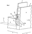
- FIG. 1 is shown in a perspective partial view of a dishwasher with a front open rinsing container 1.
- the washing container 1 is usually arranged in an outer housing 3 of the dishwasher. From the outer housing 3 are in the Fig. 1 only a housing side wall 5 and front frame elements 7, 9 can be seen, which limit a front-side charging opening of the washing compartment 1.
- the front loading opening of the washing compartment 1 is closed by means of a, about a horizontal axis of rotation 11 pivotally hinged door 13, which in the Fig. 1 only indicated by dashed lines.
- the appliance door 13 is on both sides in the usual way supported by means of hinge levers 15.
- the hinge levers 15 are in turn hinged via bearing pins 25 on lateral plate-shaped hinge support 17, of which in the Fig. 2 only one is shown.
- the hinge carrier 17 is according to the Fig. 2 an approximately angularly formed sheet metal part, the vertical leg is laterally supported in a bottom group 19 of the dishwasher.
- the hinge lever 15 of the appliance door 13 has a lever arm 21 which projects laterally below the washing container 1 through a hinge opening 23 of the vertical front frame part 7 into the housing interior.
- the lever arm 21 is operatively connected to a balancing device, not shown, which exerts a compensating moment M 1 on the appliance door 13 in a clockwise direction, which counteracts the counterclockwise acting weight moment of the appliance door 13.
- a balancing device not shown
- the hinge lever 15 is laterally mounted outside of the hinge support 17 on the bearing pin 25 in the lateral direction y.
- the lever arm 21 of the hinge lever 15 thereby moves along an outer side face of the hinge carrier 17.
- the two hinge carriers 17 arranged in each case in the lateral area of the dishwasher form, together with the intermediate appliance door 13, an overall very stiff hinge structure in the lateral direction y. This can absorb laterally acting on the opposite side walls 5 holding forces F H during a transport situation without damage.
- the front Beschikkungsö réelle the washing compartment 1 is limited by a front frame 22.
- This is in the usual way at its in the Fig. 2 shown lateral frame strip supported on the hinge support 17.
- For a firm connection with the hinge support 17 of the front frame 22 is screwed via an indicated screw 24 with the hinge plate 17.
- the two lateral hinge supports 17 are also below the Spül electer foundeds via a traverse, d. H. the indicated base rail 26, with each other in connection.
- the flat designed base rail 26 includes a mounting opening to the engine compartment from the front.
- the base rail 26 serves for noise damping and may be provided with a corresponding damping layer, such as a Bitumenlage.
- a force transmission element 27 is provided, which receives a force acting from the outside on the side wall 5 holding force F H and passes into the interior of the dishwasher.
- the power transmission element 27 is according to the Fig. 2 supported by support members 30 on the outside of the hinge support 17 shown.
- the support elements 30 are distributed over the entire hinge support 17 such that the associated force application areas I, II, III, IV are assigned to different components, ie the hinge support 17, the front frame 22 of the washing container 1, the bottom group 19 and the hinge lever 15th
- the first force introduction region I is assigned to the hinge carrier 17, while the second force introduction region II is assigned to the front frame 22.
- the force application areas I, II, III, IV mutually parallel force paths provide, with the help of the clamping forces F H on the hinge plate 17, the bottom group 19, the front frame 26 and the hinge lever 15 are distributed.
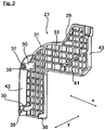
- the force transducer or the force transmission element 27 is in the Fig. 3 shown in isolation.
- the force transducer 27 is here a one-piece and integrally formed plastic molded part.
- the power take-off 27 is designed in its geometric design in lightweight construction.
- the force transducer 27 has a plate-shaped base element 29 and supporting elements 30 protruding therefrom.
- the plate-shaped base member 29 has a side facing the side wall 5 closed smooth surface to avoid during transport impressions or dents in the side wall 5.
- the closed smooth surface of the force transducer 27 is bounded by a peripheral side wall 31 which projects in the direction of the hinge support 17.
- the peripherally encircling side wall 31, together with the closed, smooth outer surface of the force transducer 27 overall, has an approximately cup-shaped structure in which truss-like reinforcing walls 33 run.
- a first support member 30 is designed as a cylindrical latching dome, on whose, the hinge support 17 facing end side centric a latching element 35 is formed.
- the locking element 35 is surrounded by an annular surface 37, which is supported on the hinge carrier 17.
- the second support member 30 has two spaced apart support webs, between which a further latching element 35 is arranged, which projects beyond the two webs in the device side direction y. Both latching elements 35 can engage behind corresponding latching openings in the hinge carrier 17.
- the third support element 30 is formed without an additional latching element 35 and is supported only on the side surface of the hinge support 17.
- the load cell 27 is laterally shown locked with the hinge carrier 17.
- the plate-shaped base member 29 is spaced by means of the support members 30 via a clearance 39 from the hinge carrier 17.
- the support members 30 are positioned so that they do not affect the pivoting S of the hinge lever 21.
- contact contour 41 is formed.
- the contact contour 41 is spaced apart in the normal state from the lever arm 21 of the hinge lever 15 in order not to impair the door pivoting movement.
- the force transducer bends elastically in the region of the contact contour 41 until it comes into contact with the lever arm 21. In this way, the holding force F H can also be introduced via the hinge lever 15 in the hinge support 17.
- the clearance 39 provided between the force transducer 27 and the hinge carrier 17 is open to the outside via the hinge opening 23 in the front frame part 7.
- the load cell 27 has sound insulation walls 43.
- a first in the depth direction x is arranged on the rear side of the force transducer 27 and separates the free space 39 to the rear from the inside of the housing.
- a vertical section of the side wall 31 lying in the depth direction x also as a sound insulation wall 43.
- the front sound insulation wall 43 of the force transducer 27 covers according to the Fig. 1 partially the hinge opening 23 of the front frame part 7, whereby the noise leakage is also reduced.
Landscapes
- Engineering & Computer Science (AREA)
- Textile Engineering (AREA)
- Washing And Drying Of Tableware (AREA)
- Main Body Construction Of Washing Machines And Laundry Dryers (AREA)
- Detergent Compositions (AREA)
- Filters For Electric Vacuum Cleaners (AREA)
- Sink And Installation For Waste Water (AREA)
- Structures Of Non-Positive Displacement Pumps (AREA)
Claims (23)
- Appareil ménager sur pieds, notamment lave-vaisselle, présentant au moins une paroi de boîtier (5) et comprenant au moins un élément de transmission de force (27) qui transmet une force (FH), agissant côté extérieur sur la paroi de boîtier (5), dans des composants (15, 17, 19, 22) de l'appareil ménager sur pieds, l'élément de transmission de force (27) présentant au moins deux zones d'introduction de force (I, II, III, IV) pour la transmission de force dans au moins deux composants différents (15, 17, 19, 22) de l'appareil ménager sur pieds, caractérisé en ce qu'une première zone d'introduction de force (I) est ménagée dans un support de charnière (17) sur lequel est articulé un levier de charnière pivotant (15) d'une porte d'appareil (13) de l'appareil ménager sur pieds.
- Appareil ménager sur pieds selon la revendication 1, caractérisé en ce qu'une deuxième zone d'introduction de force (II) est ménagée dans un cadre frontal (22) délimitant une ouverture de chargement de l'appareil ménager sur pieds.
- Appareil ménager sur pieds selon la revendication 1 ou 2, caractérisé en ce qu'une troisième zone d'introduction de force (III) est ménagée dans le levier de charnière (15) de la porte d'appareil (13).
- Appareil ménager sur pieds selon l'une quelconque des revendications précédentes, caractérisé en ce qu'une quatrième zone d'introduction de force (IV) est ménagée dans un fond (19) de l'appareil ménager sur pieds.
- Appareil ménager sur pieds selon l'une quelconque des revendications précédentes, caractérisé en ce que l'élément de transmission de force (27) présente au moins un élément d'appui (30) dépassant de celui-là, lequel est attribué à la zone d'introduction de force respective (I, II, III, IV).
- Appareil ménager sur pieds selon la revendication 5, caractérisé en ce que les éléments d'appui (30), attribués à la zone d'introduction de force (I, II, III, IV), de l'élément de transmission de force (27) sont appuyés sur le support de charnière (17).
- Appareil ménager sur pieds selon l'une quelconque des revendications 1 à 6, caractérisé en ce que deux supports de charnière opposés (17) sont ménagés, avec la porte d'appareil (13) disposée entre eux, lesquels sont raccordés par l'intermédiaire d'un rail de socle (26).
- Appareil ménager sur pieds selon l'une quelconque des revendications précédentes, caractérisé en ce que l'élément de transmission de force (27) présente un élément de base (29) en forme de plaque.
- Appareil ménager sur pieds selon la revendication 8, caractérisé en ce que l'élément de base (29) en forme de plaque présente des parois de rigidification (33) en forme de treillis.
- Appareil ménager sur pieds selon la revendication 9, caractérisé en ce que les parois de rigidification (33) et l'élément d'appui (30) sont disposés sur une surface latérale commune de l'élément de base (29).
- Appareil ménager sur pieds selon la revendication 10, caractérisé en ce que le côté, détourné de l'élément d'appui (30), de l'élément de base (29) de l'élément de transmission de force (27) est situé à l'opposé de la paroi extérieure de boîtier (5).
- Appareil ménager sur pieds selon l'une quelconque des revendications précédentes, caractérisé en ce que l'élément de transmission de force (27) est une pièce moulée par injection, en matière plastique ou en métal.
- Appareil ménager sur pieds selon l'une quelconque des revendications précédentes, caractérisé en ce que l'élément de transmission de force (27) présente des éléments d'enclenchement (35) pour la liaison d'enclenchement avec un composant (17) de l'appareil ménager sur pieds.
- Appareil ménager sur pieds selon la revendication 13, caractérisé en ce que l'élément d'enclenchement (35) est formé dans le même matériau et/ou d'une seule pièce sur l'élément d'appui (30) de l'élément de transmission de force (27).
- Appareil ménager sur pieds selon la revendication 14, caractérisé en ce que l'élément d'appui (30) de l'élément de transmission de force (27) présente une surface d'appui (37) côté frontal, sur laquelle est formé un élément d'enclenchement (35).
- Appareil ménager sur pieds selon l'une quelconque des revendications 8 à 15, caractérisé en ce que l'élément de base (29) en forme de plaque de l'élément de transmission de force (27) présente une paroi latérale (31) continue côté bord.
- Appareil ménager sur pieds selon l'une quelconque des revendications 1 à 16, caractérisé en ce que le levier de charnière (15) présente un bras de levier (21) qui est relié à un dispositif de compensation, lequel exerce sur la porte d'appareil (13) un moment de compensation (M1) agissant contrairement au moment de poids de la porte d'appareil (13).
- Appareil ménager sur pieds selon la revendication 17, caractérisé en ce que le bras de levier (21) du levier de charnière (15) est disposé entre le support de charnière (17) et l'élément de transmission de force (27).
- Appareil ménager sur pieds selon l'une quelconque des revendications 5 à 18, caractérisé en ce que l'élément d'appui (30) de l'élément de transmission de force (27) est disposé à l'extérieur d'un trajet de pivotement (S) du bras de levier (21) du levier de charnière (15).
- Appareil ménager sur pieds selon l'une quelconque des revendications 8 à 19, caractérisé en ce que l'élément de base (29) de l'élément de transmission de force (27) présente dans la partie du levier de charnière (15) un contour d'application convexe (41) qui est distancé du bras de levier (21) à l'état normal et, lors de l'application de la force, est courbé de manière élastique par la force de maintien (FH) jusqu'à être adjacent au levier de charnière (15).
- Appareil ménager sur pieds selon l'une quelconque des revendications 8 à 20, caractérisé en ce que l'élément de transmission de force (27) présente au moins une paroi d'isolation acoustique (43).
- Appareil ménager sur pieds selon la revendication 21, caractérisé en ce que la paroi d'isolation acoustique (43) s'étend d'un élément de base (29) de l'élément de transmission de force (27) jusqu'à un support de charnière (17).
- Appareil ménager sur pieds selon la revendication 21 ou 22, caractérisé en ce que la paroi d'isolation acoustique (43) de l'élément de transmission de force (27), dans un sens de sortie acoustique, recouvre au moins en partie une ouverture de levier de charnière (23) côté frontal du boîtier.
Priority Applications (1)
| Application Number | Priority Date | Filing Date | Title |
|---|---|---|---|
| PL09726579T PL2273909T5 (pl) | 2008-03-31 | 2009-03-27 | Stojące urządzenie gospodarstwa domowego, w szczególności zmywarka do naczyń |
Applications Claiming Priority (2)
| Application Number | Priority Date | Filing Date | Title |
|---|---|---|---|
| DE102008016479A DE102008016479A1 (de) | 2008-03-31 | 2008-03-31 | Haushaltsstandgerät, insbesondere Geschirrspülmaschine |
| PCT/EP2009/053691 WO2009121815A1 (fr) | 2008-03-31 | 2009-03-27 | Appareil ménager sur pieds, notamment lave-vaisselle |
Publications (3)
| Publication Number | Publication Date |
|---|---|
| EP2273909A1 EP2273909A1 (fr) | 2011-01-19 |
| EP2273909B1 EP2273909B1 (fr) | 2011-11-02 |
| EP2273909B2 true EP2273909B2 (fr) | 2017-06-21 |
Family
ID=40810451
Family Applications (1)
| Application Number | Title | Priority Date | Filing Date |
|---|---|---|---|
| EP09726579.7A Active EP2273909B2 (fr) | 2008-03-31 | 2009-03-27 | Appareil ménager sur pieds, notamment lave-vaisselle |
Country Status (9)
| Country | Link |
|---|---|
| US (1) | US9427134B2 (fr) |
| EP (1) | EP2273909B2 (fr) |
| CN (1) | CN101980649B (fr) |
| AT (1) | ATE531307T1 (fr) |
| DE (1) | DE102008016479A1 (fr) |
| ES (1) | ES2373523T5 (fr) |
| PL (1) | PL2273909T5 (fr) |
| RU (1) | RU2498763C2 (fr) |
| WO (1) | WO2009121815A1 (fr) |
Families Citing this family (7)
| Publication number | Priority date | Publication date | Assignee | Title |
|---|---|---|---|---|
| DE102011076005B4 (de) * | 2011-05-17 | 2016-07-21 | BSH Hausgeräte GmbH | Haushaltsgerät |
| DE102013216057B3 (de) * | 2013-08-14 | 2014-12-31 | BSH Bosch und Siemens Hausgeräte GmbH | Geschirrspülmaschine |
| PT108707B (pt) * | 2015-07-17 | 2020-07-15 | Shrp Equipment Corp Limited | Partícula de borracha distendida e reagida (rscr) e método de produção |
| DE102017209826A1 (de) * | 2017-06-09 | 2018-12-13 | BSH Hausgeräte GmbH | Spülbehälter und Haushaltsgeschirrspülmaschine |
| CN107595226A (zh) * | 2017-09-20 | 2018-01-19 | 佛山市顺德区美的洗涤电器制造有限公司 | 洗碗机及其底座配重缓冲结构 |
| EP3673782B1 (fr) | 2017-09-20 | 2023-11-01 | Foshan Shunde Midea Washing Appliances Manufacturing Co., Ltd. | Lave-vaisselle et ensemble base |
| US11849898B2 (en) | 2021-08-26 | 2023-12-26 | Whirlpool Corporation | Dishwasher with door assembly |
Citations (3)
| Publication number | Priority date | Publication date | Assignee | Title |
|---|---|---|---|---|
| US4746177A (en) † | 1986-11-17 | 1988-05-24 | Whirlpool Corporation | Support assembly for plastic tub dishwasher |
| DE4443920A1 (de) † | 1994-12-09 | 1996-06-13 | Bosch Siemens Hausgeraete | Haushaltgerät mit einem Rahmen |
| EP1548366A2 (fr) † | 2003-12-22 | 2005-06-29 | Electrolux Home Products Corporation N.V. | Charnière pour une porte d'un appareil électroménager |
Family Cites Families (17)
| Publication number | Priority date | Publication date | Assignee | Title |
|---|---|---|---|---|
| IT1187638B (it) * | 1985-03-13 | 1987-12-23 | Top Srl | Macchina lavastoviglie compatta a carica dall'alto da inserimento in mobili |
| DE3538974A1 (de) | 1985-11-02 | 1987-05-14 | Bauknecht Hausgeraete | Waschmaschine mit transportsicherung |
| US4787121A (en) * | 1987-10-16 | 1988-11-29 | Speed Queen Company | Hinge with stop |
| DE4438085C2 (de) | 1994-10-25 | 1996-08-08 | Bauknecht Hausgeraete | Geschirrspülmaschine mit U-förmigen Tragrahmen |
| DE4446961C2 (de) * | 1994-12-28 | 1997-03-06 | Bosch Siemens Hausgeraete | Haushaltgerät |
| US5860436A (en) * | 1996-07-31 | 1999-01-19 | White Consolidated Industries, Inc. | Offset leg |
| DE19634452A1 (de) * | 1996-08-26 | 1998-03-05 | Bosch Siemens Hausgeraete | Waschmaschine mit einem Bausatz für eine Transportsicherung |
| DE19736807C1 (de) * | 1997-08-23 | 1998-12-03 | Whirlpool Co | Geschirrspülmaschine mit aus horizontalen und vertikalen Rahmenschenkeln zusammengesetzter Tragkonstruktion |
| DE29723084U1 (de) | 1997-11-14 | 1999-04-08 | A-Z Ausrüstung und Zubehör GmbH & Co. KG, 45525 Hattingen | Einrichtung und Fixierung des schwingenden Systems einer Haushaltsmaschine |
| ITBO20000505A1 (it) | 2000-08-30 | 2002-03-02 | Cmi Srl | Cerniera controbilanciata con spostamento verticale e frontale di un portello particolarmente per lavastoviglie . |
| US7850784B2 (en) * | 2005-11-29 | 2010-12-14 | Maytag Corporation | Lid seal for a drawer-type dishwasher |
| DE102005062478A1 (de) * | 2005-12-27 | 2007-07-05 | BSH Bosch und Siemens Hausgeräte GmbH | Geschirrspülmaschine mit einer Behälterhaube aus preiswertem Stahl |
| US20110187246A1 (en) * | 2006-02-22 | 2011-08-04 | Shin Gap Su | Dish Washer |
| TR200602928A1 (tr) * | 2006-06-09 | 2009-03-23 | Bsh Ev Aletleri̇ Sanayi̇ Ve Ti̇caret Anoni̇m Şi̇rketi̇@ | Bir ev aleti. |
| US8043442B2 (en) * | 2006-11-24 | 2011-10-25 | Electrolux Home Products, Inc. | Counterbalance devices for a closure |
| US8231738B2 (en) * | 2007-07-02 | 2012-07-31 | Electrolux Home Products, Inc. | Dishwasher tub having integral hinge support member, and dishwasher incorporating same |
| DE202007013030U1 (de) * | 2007-09-17 | 2007-12-13 | BSH Bosch und Siemens Hausgeräte GmbH | Haushaltsgerät mit Einbauteil |
-
2008
- 2008-03-31 DE DE102008016479A patent/DE102008016479A1/de not_active Withdrawn
-
2009
- 2009-03-27 EP EP09726579.7A patent/EP2273909B2/fr active Active
- 2009-03-27 PL PL09726579T patent/PL2273909T5/pl unknown
- 2009-03-27 WO PCT/EP2009/053691 patent/WO2009121815A1/fr not_active Ceased
- 2009-03-27 AT AT09726579T patent/ATE531307T1/de active
- 2009-03-27 RU RU2010140987/12A patent/RU2498763C2/ru active
- 2009-03-27 US US12/934,271 patent/US9427134B2/en active Active
- 2009-03-27 ES ES09726579.7T patent/ES2373523T5/es active Active
- 2009-03-27 CN CN2009801115851A patent/CN101980649B/zh active Active
Patent Citations (3)
| Publication number | Priority date | Publication date | Assignee | Title |
|---|---|---|---|---|
| US4746177A (en) † | 1986-11-17 | 1988-05-24 | Whirlpool Corporation | Support assembly for plastic tub dishwasher |
| DE4443920A1 (de) † | 1994-12-09 | 1996-06-13 | Bosch Siemens Hausgeraete | Haushaltgerät mit einem Rahmen |
| EP1548366A2 (fr) † | 2003-12-22 | 2005-06-29 | Electrolux Home Products Corporation N.V. | Charnière pour une porte d'un appareil électroménager |
Also Published As
| Publication number | Publication date |
|---|---|
| US20110018409A1 (en) | 2011-01-27 |
| RU2498763C2 (ru) | 2013-11-20 |
| EP2273909A1 (fr) | 2011-01-19 |
| CN101980649A (zh) | 2011-02-23 |
| ES2373523T3 (es) | 2012-02-06 |
| WO2009121815A1 (fr) | 2009-10-08 |
| DE102008016479A1 (de) | 2009-10-01 |
| US9427134B2 (en) | 2016-08-30 |
| CN101980649B (zh) | 2013-04-10 |
| EP2273909B1 (fr) | 2011-11-02 |
| PL2273909T5 (pl) | 2018-02-28 |
| ES2373523T5 (es) | 2017-11-29 |
| PL2273909T3 (pl) | 2012-03-30 |
| ATE531307T1 (de) | 2011-11-15 |
| RU2010140987A (ru) | 2012-05-10 |
Similar Documents
| Publication | Publication Date | Title |
|---|---|---|
| EP2273909B2 (fr) | Appareil ménager sur pieds, notamment lave-vaisselle | |
| EP2268184B1 (fr) | Appareil ménager à circulation d'eau | |
| EP2276387B1 (fr) | Appareil électroménager fixe notamment lave-vaisselle | |
| EP2510143A1 (fr) | Appareil ménager, en particulier lave-linge ou sèche-linge | |
| WO2009068395A1 (fr) | Appareil ménager, en particulier lave-vaisselle | |
| EP4003816A1 (fr) | Structure de carrosserie pour un véhicule à fonctionnement électrique | |
| DE102013106385B4 (de) | Scharniervorrichtung | |
| EP3634196B1 (fr) | Lave-vaisselle ménager avec cuve de lavage | |
| DE102010038483B4 (de) | Einbaufähiges Haushaltsgerät | |
| EP2420177B1 (fr) | Lave-vaisselle, notamment lave-vaisselle ménager | |
| EP1956133B1 (fr) | Appareil ménager, en particulier lave-linge, lave-linge séchant ou sèche-linge, doté d'une partie de couvercle | |
| WO2013120761A1 (fr) | Appareil électroménager pourvu d'un dispositif de montage de porte | |
| DE102008032266B4 (de) | Haushaltsgerät, insbesondere Geschirrspülmaschine | |
| EP1321092B1 (fr) | Lave-vaisselle | |
| EP2484998A2 (fr) | Appareil ménager | |
| EP2426298A2 (fr) | Charnière pour une partie de carrosserie pivotante d'un véhicule | |
| EP3430966B1 (fr) | Lave-vaisselle électroménager | |
| DE102012214424B4 (de) | Geschirrspülmaschine mit wenigstens einer beidseitig gelagerten Schwenkachse für ihr Türelement | |
| DE102022214311A1 (de) | Türverbund für ein Haushaltsgerät und Haushaltsgerät | |
| DE19717974C2 (de) | Schaltschrank für Druckmaschinen | |
| EP2010021A2 (fr) | Ensemble meuble pour appareils à encastrer | |
| WO2010015558A2 (fr) | Lave-vaisselle à encastrer dans un placard | |
| EP2607545B1 (fr) | Panneau, notamment pour appareils ménagers | |
| DE102024103107A1 (de) | Haushaltsgerät | |
| DE102011076005B4 (de) | Haushaltsgerät |
Legal Events
| Date | Code | Title | Description |
|---|---|---|---|
| PUAI | Public reference made under article 153(3) epc to a published international application that has entered the european phase |
Free format text: ORIGINAL CODE: 0009012 |
|
| 17P | Request for examination filed |
Effective date: 20101102 |
|
| AK | Designated contracting states |
Kind code of ref document: A1 Designated state(s): AT BE BG CH CY CZ DE DK EE ES FI FR GB GR HR HU IE IS IT LI LT LU LV MC MK MT NL NO PL PT RO SE SI SK TR |
|
| AX | Request for extension of the european patent |
Extension state: AL BA RS |
|
| GRAP | Despatch of communication of intention to grant a patent |
Free format text: ORIGINAL CODE: EPIDOSNIGR1 |
|
| DAX | Request for extension of the european patent (deleted) | ||
| GRAS | Grant fee paid |
Free format text: ORIGINAL CODE: EPIDOSNIGR3 |
|
| GRAA | (expected) grant |
Free format text: ORIGINAL CODE: 0009210 |
|
| AK | Designated contracting states |
Kind code of ref document: B1 Designated state(s): AT BE BG CH CY CZ DE DK EE ES FI FR GB GR HR HU IE IS IT LI LT LU LV MC MK MT NL NO PL PT RO SE SI SK TR |
|
| REG | Reference to a national code |
Ref country code: GB Ref legal event code: FG4D Free format text: NOT ENGLISH |
|
| REG | Reference to a national code |
Ref country code: CH Ref legal event code: EP |
|
| REG | Reference to a national code |
Ref country code: IE Ref legal event code: FG4D |
|
| REG | Reference to a national code |
Ref country code: DE Ref legal event code: R096 Ref document number: 502009001809 Country of ref document: DE Effective date: 20111229 |
|
| REG | Reference to a national code |
Ref country code: ES Ref legal event code: FG2A Ref document number: 2373523 Country of ref document: ES Kind code of ref document: T3 Effective date: 20120206 |
|
| REG | Reference to a national code |
Ref country code: NL Ref legal event code: VDEP Effective date: 20111102 |
|
| REG | Reference to a national code |
Ref country code: PL Ref legal event code: T3 |
|
| LTIE | Lt: invalidation of european patent or patent extension |
Effective date: 20111102 |
|
| PG25 | Lapsed in a contracting state [announced via postgrant information from national office to epo] |
Ref country code: IS Free format text: LAPSE BECAUSE OF FAILURE TO SUBMIT A TRANSLATION OF THE DESCRIPTION OR TO PAY THE FEE WITHIN THE PRESCRIBED TIME-LIMIT Effective date: 20120302 Ref country code: NO Free format text: LAPSE BECAUSE OF FAILURE TO SUBMIT A TRANSLATION OF THE DESCRIPTION OR TO PAY THE FEE WITHIN THE PRESCRIBED TIME-LIMIT Effective date: 20120202 Ref country code: LT Free format text: LAPSE BECAUSE OF FAILURE TO SUBMIT A TRANSLATION OF THE DESCRIPTION OR TO PAY THE FEE WITHIN THE PRESCRIBED TIME-LIMIT Effective date: 20111102 |
|
| PG25 | Lapsed in a contracting state [announced via postgrant information from national office to epo] |
Ref country code: SI Free format text: LAPSE BECAUSE OF FAILURE TO SUBMIT A TRANSLATION OF THE DESCRIPTION OR TO PAY THE FEE WITHIN THE PRESCRIBED TIME-LIMIT Effective date: 20111102 Ref country code: NL Free format text: LAPSE BECAUSE OF FAILURE TO SUBMIT A TRANSLATION OF THE DESCRIPTION OR TO PAY THE FEE WITHIN THE PRESCRIBED TIME-LIMIT Effective date: 20111102 Ref country code: GR Free format text: LAPSE BECAUSE OF FAILURE TO SUBMIT A TRANSLATION OF THE DESCRIPTION OR TO PAY THE FEE WITHIN THE PRESCRIBED TIME-LIMIT Effective date: 20120203 Ref country code: SE Free format text: LAPSE BECAUSE OF FAILURE TO SUBMIT A TRANSLATION OF THE DESCRIPTION OR TO PAY THE FEE WITHIN THE PRESCRIBED TIME-LIMIT Effective date: 20111102 Ref country code: PT Free format text: LAPSE BECAUSE OF FAILURE TO SUBMIT A TRANSLATION OF THE DESCRIPTION OR TO PAY THE FEE WITHIN THE PRESCRIBED TIME-LIMIT Effective date: 20120302 Ref country code: LV Free format text: LAPSE BECAUSE OF FAILURE TO SUBMIT A TRANSLATION OF THE DESCRIPTION OR TO PAY THE FEE WITHIN THE PRESCRIBED TIME-LIMIT Effective date: 20111102 Ref country code: HR Free format text: LAPSE BECAUSE OF FAILURE TO SUBMIT A TRANSLATION OF THE DESCRIPTION OR TO PAY THE FEE WITHIN THE PRESCRIBED TIME-LIMIT Effective date: 20111102 |
|
| REG | Reference to a national code |
Ref country code: IE Ref legal event code: FD4D |
|
| PG25 | Lapsed in a contracting state [announced via postgrant information from national office to epo] |
Ref country code: CY Free format text: LAPSE BECAUSE OF FAILURE TO SUBMIT A TRANSLATION OF THE DESCRIPTION OR TO PAY THE FEE WITHIN THE PRESCRIBED TIME-LIMIT Effective date: 20111102 |
|
| PG25 | Lapsed in a contracting state [announced via postgrant information from national office to epo] |
Ref country code: CZ Free format text: LAPSE BECAUSE OF FAILURE TO SUBMIT A TRANSLATION OF THE DESCRIPTION OR TO PAY THE FEE WITHIN THE PRESCRIBED TIME-LIMIT Effective date: 20111102 Ref country code: BG Free format text: LAPSE BECAUSE OF FAILURE TO SUBMIT A TRANSLATION OF THE DESCRIPTION OR TO PAY THE FEE WITHIN THE PRESCRIBED TIME-LIMIT Effective date: 20120202 Ref country code: EE Free format text: LAPSE BECAUSE OF FAILURE TO SUBMIT A TRANSLATION OF THE DESCRIPTION OR TO PAY THE FEE WITHIN THE PRESCRIBED TIME-LIMIT Effective date: 20111102 Ref country code: DK Free format text: LAPSE BECAUSE OF FAILURE TO SUBMIT A TRANSLATION OF THE DESCRIPTION OR TO PAY THE FEE WITHIN THE PRESCRIBED TIME-LIMIT Effective date: 20111102 Ref country code: IE Free format text: LAPSE BECAUSE OF FAILURE TO SUBMIT A TRANSLATION OF THE DESCRIPTION OR TO PAY THE FEE WITHIN THE PRESCRIBED TIME-LIMIT Effective date: 20111102 Ref country code: SK Free format text: LAPSE BECAUSE OF FAILURE TO SUBMIT A TRANSLATION OF THE DESCRIPTION OR TO PAY THE FEE WITHIN THE PRESCRIBED TIME-LIMIT Effective date: 20111102 |
|
| PLBI | Opposition filed |
Free format text: ORIGINAL CODE: 0009260 |
|
| PG25 | Lapsed in a contracting state [announced via postgrant information from national office to epo] |
Ref country code: RO Free format text: LAPSE BECAUSE OF FAILURE TO SUBMIT A TRANSLATION OF THE DESCRIPTION OR TO PAY THE FEE WITHIN THE PRESCRIBED TIME-LIMIT Effective date: 20111102 |
|
| PLAX | Notice of opposition and request to file observation + time limit sent |
Free format text: ORIGINAL CODE: EPIDOSNOBS2 |
|
| 26 | Opposition filed |
Opponent name: ELECTROLUX APPLIANCES AKTIEBOLAG Effective date: 20120802 |
|
| BERE | Be: lapsed |
Owner name: BSH BOSCH UND SIEMENS HAUSGERATE G.M.B.H. Effective date: 20120331 |
|
| PG25 | Lapsed in a contracting state [announced via postgrant information from national office to epo] |
Ref country code: MC Free format text: LAPSE BECAUSE OF NON-PAYMENT OF DUE FEES Effective date: 20120331 |
|
| REG | Reference to a national code |
Ref country code: DE Ref legal event code: R026 Ref document number: 502009001809 Country of ref document: DE Effective date: 20120802 |
|
| PLAF | Information modified related to communication of a notice of opposition and request to file observations + time limit |
Free format text: ORIGINAL CODE: EPIDOSCOBS2 |
|
| PG25 | Lapsed in a contracting state [announced via postgrant information from national office to epo] |
Ref country code: BE Free format text: LAPSE BECAUSE OF NON-PAYMENT OF DUE FEES Effective date: 20120331 |
|
| PG25 | Lapsed in a contracting state [announced via postgrant information from national office to epo] |
Ref country code: MK Free format text: LAPSE BECAUSE OF FAILURE TO SUBMIT A TRANSLATION OF THE DESCRIPTION OR TO PAY THE FEE WITHIN THE PRESCRIBED TIME-LIMIT Effective date: 20111102 |
|
| PLBB | Reply of patent proprietor to notice(s) of opposition received |
Free format text: ORIGINAL CODE: EPIDOSNOBS3 |
|
| PG25 | Lapsed in a contracting state [announced via postgrant information from national office to epo] |
Ref country code: FI Free format text: LAPSE BECAUSE OF FAILURE TO SUBMIT A TRANSLATION OF THE DESCRIPTION OR TO PAY THE FEE WITHIN THE PRESCRIBED TIME-LIMIT Effective date: 20111102 |
|
| PG25 | Lapsed in a contracting state [announced via postgrant information from national office to epo] |
Ref country code: MT Free format text: LAPSE BECAUSE OF FAILURE TO SUBMIT A TRANSLATION OF THE DESCRIPTION OR TO PAY THE FEE WITHIN THE PRESCRIBED TIME-LIMIT Effective date: 20111102 |
|
| REG | Reference to a national code |
Ref country code: CH Ref legal event code: PL |
|
| GBPC | Gb: european patent ceased through non-payment of renewal fee |
Effective date: 20130327 |
|
| PG25 | Lapsed in a contracting state [announced via postgrant information from national office to epo] |
Ref country code: GB Free format text: LAPSE BECAUSE OF NON-PAYMENT OF DUE FEES Effective date: 20130327 Ref country code: CH Free format text: LAPSE BECAUSE OF NON-PAYMENT OF DUE FEES Effective date: 20130331 Ref country code: LI Free format text: LAPSE BECAUSE OF NON-PAYMENT OF DUE FEES Effective date: 20130331 |
|
| PG25 | Lapsed in a contracting state [announced via postgrant information from national office to epo] |
Ref country code: LU Free format text: LAPSE BECAUSE OF NON-PAYMENT OF DUE FEES Effective date: 20120327 |
|
| PG25 | Lapsed in a contracting state [announced via postgrant information from national office to epo] |
Ref country code: HU Free format text: LAPSE BECAUSE OF FAILURE TO SUBMIT A TRANSLATION OF THE DESCRIPTION OR TO PAY THE FEE WITHIN THE PRESCRIBED TIME-LIMIT Effective date: 20090327 |
|
| REG | Reference to a national code |
Ref country code: FR Ref legal event code: PLFP Year of fee payment: 7 |
|
| RAP2 | Party data changed (patent owner data changed or rights of a patent transferred) |
Owner name: BSH HAUSGERAETE GMBH |
|
| REG | Reference to a national code |
Ref country code: DE Ref legal event code: R081 Ref document number: 502009001809 Country of ref document: DE Owner name: BSH HAUSGERAETE GMBH, DE Free format text: FORMER OWNER: BSH BOSCH UND SIEMENS HAUSGERAETE GMBH, 81739 MUENCHEN, DE Effective date: 20150407 |
|
| REG | Reference to a national code |
Ref country code: AT Ref legal event code: MM01 Ref document number: 531307 Country of ref document: AT Kind code of ref document: T Effective date: 20140327 |
|
| REG | Reference to a national code |
Ref country code: ES Ref legal event code: PC2A Owner name: BSH HAUSGERATE GMBH Effective date: 20150529 |
|
| PG25 | Lapsed in a contracting state [announced via postgrant information from national office to epo] |
Ref country code: AT Free format text: LAPSE BECAUSE OF NON-PAYMENT OF DUE FEES Effective date: 20140327 |
|
| REG | Reference to a national code |
Ref country code: FR Ref legal event code: CD Owner name: BSH HAUSGERATE GMBH, DE Effective date: 20151022 |
|
| REG | Reference to a national code |
Ref country code: FR Ref legal event code: PLFP Year of fee payment: 8 |
|
| REG | Reference to a national code |
Ref country code: FR Ref legal event code: PLFP Year of fee payment: 9 |
|
| PUAH | Patent maintained in amended form |
Free format text: ORIGINAL CODE: 0009272 |
|
| STAA | Information on the status of an ep patent application or granted ep patent |
Free format text: STATUS: PATENT MAINTAINED AS AMENDED |
|
| 27A | Patent maintained in amended form |
Effective date: 20170621 |
|
| AK | Designated contracting states |
Kind code of ref document: B2 Designated state(s): AT BE BG CH CY CZ DE DK EE ES FI FR GB GR HR HU IE IS IT LI LT LU LV MC MK MT NL NO PL PT RO SE SI SK TR |
|
| REG | Reference to a national code |
Ref country code: DE Ref legal event code: R102 Ref document number: 502009001809 Country of ref document: DE |
|
| REG | Reference to a national code |
Ref country code: FR Ref legal event code: PLFP Year of fee payment: 10 |
|
| PGFP | Annual fee paid to national office [announced via postgrant information from national office to epo] |
Ref country code: IT Payment date: 20240329 Year of fee payment: 16 Ref country code: FR Payment date: 20240320 Year of fee payment: 16 |
|
| PGFP | Annual fee paid to national office [announced via postgrant information from national office to epo] |
Ref country code: ES Payment date: 20240417 Year of fee payment: 16 |
|
| PG25 | Lapsed in a contracting state [announced via postgrant information from national office to epo] |
Ref country code: IT Free format text: LAPSE BECAUSE OF NON-PAYMENT OF DUE FEES Effective date: 20250327 Ref country code: FR Free format text: LAPSE BECAUSE OF NON-PAYMENT OF DUE FEES Effective date: 20250331 |
|
| PGFP | Annual fee paid to national office [announced via postgrant information from national office to epo] |
Ref country code: DE Payment date: 20260331 Year of fee payment: 18 |
|
| PGFP | Annual fee paid to national office [announced via postgrant information from national office to epo] |
Ref country code: TR Payment date: 20260325 Year of fee payment: 18 |
|
| PGFP | Annual fee paid to national office [announced via postgrant information from national office to epo] |
Ref country code: PL Payment date: 20260325 Year of fee payment: 18 |