EP2275382A2 - Sattel und Sattelbaum - Google Patents
Sattel und Sattelbaum Download PDFInfo
- Publication number
- EP2275382A2 EP2275382A2 EP10169741A EP10169741A EP2275382A2 EP 2275382 A2 EP2275382 A2 EP 2275382A2 EP 10169741 A EP10169741 A EP 10169741A EP 10169741 A EP10169741 A EP 10169741A EP 2275382 A2 EP2275382 A2 EP 2275382A2
- Authority
- EP
- European Patent Office
- Prior art keywords
- saddle
- tree
- saddle tree
- load
- pommel
- Prior art date
- Legal status (The legal status is an assumption and is not a legal conclusion. Google has not performed a legal analysis and makes no representation as to the accuracy of the status listed.)
- Granted
Links
Images


Classifications
-
- B—PERFORMING OPERATIONS; TRANSPORTING
- B68—SADDLERY; UPHOLSTERY
- B68C—SADDLES; STIRRUPS
- B68C1/00—Saddling equipment for riding- or pack-animals
- B68C1/02—Saddles
- B68C1/025—Saddle-trees
-
- B—PERFORMING OPERATIONS; TRANSPORTING
- B68—SADDLERY; UPHOLSTERY
- B68C—SADDLES; STIRRUPS
- B68C1/00—Saddling equipment for riding- or pack-animals
- B68C1/02—Saddles
- B68C1/04—Adjustable saddles
-
- B—PERFORMING OPERATIONS; TRANSPORTING
- B68—SADDLERY; UPHOLSTERY
- B68C—SADDLES; STIRRUPS
- B68C1/00—Saddling equipment for riding- or pack-animals
- B68C1/02—Saddles
- B68C1/04—Adjustable saddles
- B68C2001/042—Adjustable saddles self-adjustable by means of articulations
Definitions
- the present invention relates to a saddle for a load-carrying animal, intended and adapted to be received on a back of the load-carrying animal, comprising a saddle tree with a pommel and a cantle which are mutually separated in a longitudinal direction by a connecting part, wherein the pommel comprises at least a part of a saddle head and a pair of saddle tree points which hang downward on either side thereof and between which a saddle channel is situated.
- the invention also relates to a saddle tree for use in the saddle according to the present invention.
- Riding saddles are used on load-carrying animals, such as for instance horses and donkeys, in order to improve a riding experience during riding of the load-carrying animal for both the rider and the load-carrying animal itself.
- the riding saddle serves here on the one hand to enhance the sitting comfort of the rider during riding and on the other to reduce or prevent possible physical injuries to the load-carrying animal resulting from riding.
- An important component in many known riding saddles is the saddle tree.
- the saddle tree is the structural core of the saddle which provides the saddle with its shape and strength and to which other saddle components, such as the saddle panels, are fixed.
- a conventional saddle tree comprises a pommel and a cantle which are separated from each other by a connecting part.
- the connecting part of the saddle tree When applied in a saddle the connecting part of the saddle tree usually receives thereon a seat element, such as a seat panel, on which a rider can support comfortably during riding, and thereunder a support panel for supporting on the back of the load-carrying animal therewith.
- the cantle extends upward and functions as back support for the rider during riding.
- the pommel comprises a pair of saddle tree points which hang downward along a part of the withers of the load-carrying animal. Situated between the saddle tree points is a saddle channel in which a part of the back of the load-carrying animal is received during use.
- the saddle channel must be sufficiently large to receive a back part of the riding animal therein without squeezing, and must also leave space between the saddle tree and the spine of the load-carrying animal during use so that the spine can move freely and is not directly loaded by the weight of the rider.
- the forces released during riding are dispersed along the flanks of the load-carrying animal toward the back muscles via the saddle tree points so that these forces are distributed over a large area, so providing a large measure of relief for particularly the spine of the load-carrying animal.
- the present invention thus has for its object, among others, to provide a riding saddle which obviates the stated drawback.
- a riding saddle of the type stated in the preamble has the feature according to the present invention that a downward hanging wall extends on either side of the saddle tree from the saddle tree points along a part of a length of the connecting part.
- the downward hanging wall forms a wing on the saddle tree, which during use of the saddle supports on a part of the flanks of the load-carrying animal in order to increase a load-bearing capacity of the saddle tree and thus increase wear comfort for the load-carrying animal.
- Lower panels, such as the support panels, applied under the saddle tree can thereby be displaced without loss of wear comfort of the riding saddle.
- the downward hanging wall here also provides a mounting body for reliable mounting of the lower panels.
- the downward hanging wall extends only along a front part of the connecting part on a pommel side and leaves a rear part of the connecting part on a cantle side free so that using his/her legs a rider can make substantially direct contact here with the load-carrying animal, i.e. without interposing of a downward hanging wall of the saddle tree.
- a preferred embodiment of the riding saddle according to the present invention has the feature that connecting means are provided to mutually connect the downward hanging wall and the saddle tree.
- the downward hanging wall can thus be connected for instance mechanically to the saddle tree.
- the riding saddle according to the present invention is characterized in that the downward hanging wall comprises a cavity for receiving at least a part of a saddle tree point therein.
- a particular embodiment of the riding saddle according to present invention has the feature that the downward hanging wall can be pivoted manually relative to the at least part of the saddle head in a width direction between a first position and a further position, and can be fixed in a position.
- the pommel can be adjusted by heating the material so that it becomes to some extent flexible, and subsequently bending the material in order to adjust a width of the saddle channel as required.
- this known riding saddle can be widely applied owing to the adjustability and can for instance be used on different load-carrying animals of varying build and size, it does however also have a drawback.
- During bending of the saddle-bow of the known riding saddle there is a bending moment at the top of the saddle head. This also changes a shape of an upper part of the saddle head. Such a change is visible and perceptible in a seat part of the riding saddle in which the saddle tree is applied. This results for a rider in a changed riding experience, and particularly in a reduced sitting comfort, of the riding saddle.
- the present invention thus has the further object of providing a riding saddle which is easily adjustable in size without a sitting comfort of the riding saddle being affected therein.
- a riding saddle of the type stated in the preamble is characterized according to the invention in that the saddle tree points can be pivoted manually relative to the at least part of the saddle head in a width direction between a first position and at least one further position, and that the saddle tree points can be fixed in a position. Because the saddle tree points are manually pivotable in a width direction, the size of a space provided by the saddle channel can be adjusted in simple manner to the dimensions of a back part of a load-carrying animal on which the riding saddle is used.
- the riding saddle need not therefore be replaced when there is a change in the build of the load-carrying animal for which the saddle was in the first instance acquired, such as for instance an increase or decrease of muscle mass on the back, particularly at the position of the withers.
- the riding saddle can moreover be used on different riding animals of varying build.
- the riding saddle is thus exceptionally versatile and saves the cost of additional riding saddles. Because the saddle tree points are adjustable here in a width direction relative to the at least part of the saddle head, the at least part of the saddle head remains unaffected when the saddle tree is adjusted. An original design of the upper side of the saddle, particularly the sitting part, which is particularly important for the sitting comfort, here remains largely the same. The riding characteristics of the saddle will thus also remain the same after a modification thereof for the rider.
- a preferred embodiment of the riding saddle according to the present invention has the feature that the saddle tree points are each mounted along a pivot axis on the at least part of the saddle head.
- the pivot axis can thus for instance comprise a hinge along which each saddle tree point can be manually adjusted in a width direction in simple manner.
- the riding saddle according to the present invention is characterized in that the pommel is formed at least substantially integrally and is provided between the at least part of the saddle head and each saddle tree point with a weakening line along which the saddle tree point can be pivoted.
- the weakening line can be realized in the pommel between the at least part of the saddle head and each saddle tree point in many ways, and in a further preferred embodiment of the riding saddle according to the present invention comprises a groove, crease line or other type of material-saving, because such weakening lines can be arranged later in the material of the pommel in very simple manner.
- a further preferred embodiment of the riding saddle according to the present invention has the feature that a strengthening body fixes the saddle tree points in a position.
- a strengthening body it is for instance possible to apply an at least practically non-deformable metal or plastic body, such as for instance a steel head iron, which is able and adapted to absorb the forces possibly released on particularly the saddle tree points during riding of the load-carrying animal.
- the strengthening body can be fixed here in the saddle channel against an inner side of the saddle tree points and the at least part of the saddle head or, conversely, against an opposite outer side of the saddle tree points and the at least part of the saddle head.
- the strengthening body prevents unwanted pivoting of the saddle tree points to a different position, which could have serious consequences for both the load-carrying animal and the rider.
- the present invention also relates to a riding saddle for a load-carrying animal, intended and adapted to be received on the back of the load-carrying animal, comprising a saddle tree with a pommel and a cantle which are mutually separated in a longitudinal direction by a connecting part, wherein the pommel comprises at least a part of a saddle head and a pair of saddle tree points which hang downward on either side thereof and between which a saddle channel is situated, which riding saddle is characterized in that on either side of the saddle tree a downward hanging wall extends from the saddle tree points along a part of a length of the connecting part and is intended and adapted to receive at least one panel thereon.
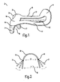
- the riding saddle comprises a saddle tree 2 with a pommel 3 and a cantle 4, which are separated from each other by a connecting part 5.
- Saddle tree 2 can be formed integrally or from separate components 3, 4, 5.
- Saddle tree 2 or separate components 3, 4, 5 thereof can be manufactured from any suitable material which is sufficiently flexible and strong, but are preferably made of wood, plastic or metal or combinations thereof.
- Cantle 4 extends upward to some extent relative to connecting part 5 in order to function as back support for a rider.
- Connecting part 5 forms the waist of the saddle, on which a sitting element such as for instance a seat panel is arranged to allow comfortable seating of a rider thereon during riding.
- Connecting part 5 Arranged under connecting part 5 are support panels which increase the saddle comfort for the load-carrying animal on which the saddle is used.
- Connecting part 5 can be formed by a fully closed plate between the pommel and cantle, but comprises in this exemplary embodiment two supports 11 which leave an opening between them. Owing to the opening this exemplary embodiment is a lightweight saddle tree.
- Connecting part 5 can optionally be strengthened by applying a number of strengthening bodies, for instance in the form of metal strips 12.
- Pommel 3 comprises a part of a saddle head 6 and a pair of downward hanging saddle tree points 7.
- Saddle tree points 7 extend downward along a part of the withers of the load-carrying animal in order to distribute the forces released during riding over the flanks of the load-carrying animal so that the relatively injury-susceptible spine, particularly the wither vertebrae, of the load-carrying animal are providing with a large measure of relief.
- a saddle channel 8 Situated between saddle tree points 7 is a saddle channel 8 in which a part of the back of the load-carrying animal is received during use.
- Saddle channel 8 must be sufficiently large to receive a back part of the load-carrying animal therein without squeezing and must leave sufficient space between the saddle tree and the spine of the load-carrying animal during use so that the spine can move freely.
- a width of the saddle channel and a height of the saddle channel are both important here.
- Saddle tree points 7 can be manually adjusted in a width direction along a pivot axis 9 to enable adjustment of the width of the saddle channel. Because only the width of saddle tree points 7 is adjusted here, the part of saddle head 6 remains unaffected. A height of the part of the saddle head relative to the connecting part remains practically the same. The riding characteristics, and particularly the riding comfort, hereby also remain the same for the rider.
- a front view of the pommel clearly shows that saddle tree points 7 can be adjusted in a width direction along pivot axis 9 independently of the at least part of saddle head 6. No change occurs here in saddle head 6.
- a width of saddle channel 8 between saddle tree points 7, designated with arrow Y, can thus be manually adjusted in simple manner, while a width of saddle channel 8 above the saddle tree points in saddle head 6, designated with arrow X, remains constant.
- a second embodiment of a riding saddle according to the invention is almost the same as the first embodiment and is shown in figure 3 .
- saddle tree 2 comprises on either side a downward hanging wall 13 extending from a saddle tree point 7 along a part of a length of connecting part 5.
- Downward hanging wall 13 forms a wing on the saddle tree, which rests on the flanks of a load-carrying animal during use of the saddle in order to increase a load-bearing capacity of the saddle tree.
- the downward hanging wall 13 leaves free a rear part of connecting part 5 on a cantle side so that a rider can here make substantially direct contact with the load-carrying animal with his/her legs, i.e. without interposing of a downward hanging wall of the saddle tree.
- the downward hanging wall 13 can be pivoted manually together with saddle tree point 7 in a width direction relative to the saddle tree for the same reasons as described above.
- Figure 4 shows clearly that in this exemplary embodiment the downward hanging wall 13 comprises a cavity in which a saddle tree point 7 is received.
- the downward hanging wall can hereby be fixed in simple manner to an existing saddle tree with saddle tree points.
- connecting means can also be provided which mutually connect the downward hanging wall 13 and the saddle tree.
- the downward hanging wall is formed integrally with the saddle tree point and is coupled to the saddle tree via pivot axis 9. It is also possible to manufacture the downward hanging wall 13 integrally with the pommel or with the complete saddle-bow.
- a third embodiment of a riding saddle shows a saddle tree 2 which is placed on the back of the load-carrying animal with a pommel 3 close to the withers.
- Pommel 3 comprises at least a part of a saddle head 6, wherein an upper part 14 (see figure 6 ) of the at least part of saddle head 6 is coupled releasably to a basic part 15 of the at least part of saddle head 6.
- Pommel 3 further comprises saddle tree points 7 which on either side of saddle tree 2 are integral with a respective downward hanging wall 13 of at least substantially triangular form (see figure 7 ) attached releasably to an underside of basic part 15.
- Basic part 15 of the at least part of saddle head 6 is formed integrally with a connecting part 5 on which a seat panel can be arranged and under which a support panel can be mounted for the purpose of manufacturing a riding saddle.
- Connecting part 5 is formed integrally with a cantle 4 which serves as a back support for a rider.
- a strengthening body 16 in the form of a steel head iron (see figure 8 ) is placed in the saddle channel on an inner side of the saddle tree.
- the head iron of hardened steel does not deform even when a maximal load is exerted thereon during a ride on the load-carrying animal, and is thus very well able to fix saddle tree points 7 in a position.
- the head iron comprises a bend line 17, for instance in the form of a crease line or other type of recess, to enable pivoting of a bottom part of head iron 16 together with saddle tree points 7 from a first position to at least one further position
- a size of the saddle channel between the downward hanging saddle tree points 7 and downward hanging wall 13 is thus adjustable.
- head iron 16 can only be adjusted around the bend line with a minimal force greater than a maximal force as is exerted on saddle tree points 7 and downward hanging wall 13 during normal use of saddle tree 2 during a ride on the load-carrying animal.
- a strengthening body 16 such as a head iron, without bend line.
- the strengthening body 16 will in that case have to be exchanged for another strengthening body 16 from a pair of strengthening bodies which vary in dimension and shape.
- saddle tree 2 can be very flexible in use.
- Saddle tree points 7 and upper part 14 can both be exchanged in simple manner with other saddle tree points or upper part from a collection of different saddle tree points and upper parts varying in dimension and shape.
- Upper part 14 of figure 6 is for instance embodied with a cut-back head, wherein upper part 14 comprises a recess on an upper side in order to provide a load-carrying animal with relatively high withers more space to move.
- Upper part 14 can however also comprise a full saddle head as shown in figure 9 , and be part of an integrally formed pommel comprising an upper part 14 and basic part 15 and a part of a downward hanging wall 13 ( figure 9 ).
- the saddle tree can thus be precisely modified to the dimensions of the load-carrying animal on which the saddle tree is applied.
Landscapes
- Engineering & Computer Science (AREA)
- Mechanical Engineering (AREA)
- Supports Or Holders For Household Use (AREA)
- Catching Or Destruction (AREA)
- Supports For Plants (AREA)
Applications Claiming Priority (1)
| Application Number | Priority Date | Filing Date | Title |
|---|---|---|---|
| NL2003234A NL2003234C2 (nl) | 2009-07-17 | 2009-07-17 | Rijzadel voor een lastdier en een zadelboom. |
Publications (3)
| Publication Number | Publication Date |
|---|---|
| EP2275382A2 true EP2275382A2 (de) | 2011-01-19 |
| EP2275382A3 EP2275382A3 (de) | 2013-01-02 |
| EP2275382B1 EP2275382B1 (de) | 2019-01-23 |
Family
ID=43067041
Family Applications (1)
| Application Number | Title | Priority Date | Filing Date |
|---|---|---|---|
| EP10169741.5A Not-in-force EP2275382B1 (de) | 2009-07-17 | 2010-07-15 | Sattel und Sattelbaum |
Country Status (2)
| Country | Link |
|---|---|
| EP (1) | EP2275382B1 (de) |
| NL (1) | NL2003234C2 (de) |
Cited By (4)
| Publication number | Priority date | Publication date | Assignee | Title |
|---|---|---|---|---|
| DE102012103250A1 (de) * | 2012-04-13 | 2013-10-17 | Dt Saddlery Gmbh Design & Technik | Vorrichtung für eine Sitzauflage eines Reit- oder Transporttieres |
| DE102013105569A1 (de) * | 2013-05-29 | 2014-12-04 | Jochen Hennig | Flexibler Sattelbaum mit einem ein- oder mehrstückigen Kopfeisen |
| DE102014016721A1 (de) * | 2014-11-13 | 2016-05-19 | Dieter Preiss | Kopfeisen, Sattelbaum und Reitsattel |
| WO2024260935A1 (en) | 2023-06-17 | 2024-12-26 | Ergon Equine Ltd | Modular saddle tree and cantle |
Families Citing this family (1)
| Publication number | Priority date | Publication date | Assignee | Title |
|---|---|---|---|---|
| GB202103894D0 (en) | 2021-03-19 | 2021-05-05 | Ergon Equine Ltd | Improvements in or relating to saddles |
Family Cites Families (8)
| Publication number | Priority date | Publication date | Assignee | Title |
|---|---|---|---|---|
| DE83369C (de) * | ||||
| DE84008C (de) * | ||||
| GB189903214A (en) * | 1899-02-14 | 1900-02-02 | Eliza Mary Fitzroy | Improvements in Saddle-trees. |
| EP0328376B1 (de) * | 1988-02-11 | 1991-10-09 | Wellep International (Uk) Limited | Kammerbügel und Baum für Sattel |
| GB2330513B (en) * | 1997-10-27 | 2002-06-26 | Barry Swain | Saddle tree |
| CA2255428A1 (en) * | 1998-12-11 | 2000-06-11 | Bernard Girault | Saddle tree |
| GB2423230A (en) * | 2005-02-18 | 2006-08-23 | Jabez Cliff & Company Ltd | Adjustable saddle tree |
| US8789350B2 (en) * | 2006-10-11 | 2014-07-29 | Pedro Ruiz Diaz | Adjustable saddle and adjusting assembly |
-
2009
- 2009-07-17 NL NL2003234A patent/NL2003234C2/nl not_active IP Right Cessation
-
2010
- 2010-07-15 EP EP10169741.5A patent/EP2275382B1/de not_active Not-in-force
Non-Patent Citations (1)
| Title |
|---|
| None |
Cited By (10)
| Publication number | Priority date | Publication date | Assignee | Title |
|---|---|---|---|---|
| DE102012103250A1 (de) * | 2012-04-13 | 2013-10-17 | Dt Saddlery Gmbh Design & Technik | Vorrichtung für eine Sitzauflage eines Reit- oder Transporttieres |
| US8997444B2 (en) | 2012-04-13 | 2015-04-07 | Dt Saddlery Gmbh Design & Technik | Seat support device for a riding animal or a pack animal |
| EP2660189A3 (de) * | 2012-04-13 | 2015-08-12 | dt Saddlery GmbH design & technik | Vorrichtung für eine Sitzauflage eines Reit- oder Transporttieres |
| DE102012103250B4 (de) * | 2012-04-13 | 2015-08-20 | Dt Saddlery Gmbh Design & Technik | Vorrichtung für eine Sitzauflage eines Reit- oder Transporttieres |
| US9556014B2 (en) | 2012-04-13 | 2017-01-31 | Dt Saddlery Gmbh Design & Technik | Seat support device for a riding animal or a pack animal |
| DE102013105569A1 (de) * | 2013-05-29 | 2014-12-04 | Jochen Hennig | Flexibler Sattelbaum mit einem ein- oder mehrstückigen Kopfeisen |
| EP3003963B1 (de) * | 2013-05-29 | 2018-03-28 | Jochen Hennig | Modularer sattelbaum mit einem kopfeisen |
| DE102014016721A1 (de) * | 2014-11-13 | 2016-05-19 | Dieter Preiss | Kopfeisen, Sattelbaum und Reitsattel |
| DE102014016721B4 (de) * | 2014-11-13 | 2016-11-17 | Dieter Preiss | Kopfeisen, Sattelbaum und Reitsattel |
| WO2024260935A1 (en) | 2023-06-17 | 2024-12-26 | Ergon Equine Ltd | Modular saddle tree and cantle |
Also Published As
| Publication number | Publication date |
|---|---|
| EP2275382B1 (de) | 2019-01-23 |
| EP2275382A3 (de) | 2013-01-02 |
| NL2003234C2 (nl) | 2011-01-18 |
Similar Documents
| Publication | Publication Date | Title |
|---|---|---|
| EP2275382B1 (de) | Sattel und Sattelbaum | |
| AU2013201358B2 (en) | Device for a seat support suitable for a riding animal or a pack animal | |
| US9315374B2 (en) | Adjustable frame for a riding saddle that does not require disassembly | |
| US11299389B2 (en) | Saddle with interface having passively morphing elements and method of use | |
| US8627641B2 (en) | Saddle | |
| EP3294663B1 (de) | Sattel | |
| GB2423230A (en) | Adjustable saddle tree | |
| CA2332226C (en) | Saddletree with resilient supporting elements | |
| WO2012018466A1 (en) | Suspension saddle | |
| EP4232405B1 (de) | Sattel und verwendung dieses sattels zur sitzunterstützung eines reiters auf einem tier, insbesondere auf einem pferd | |
| JP2008539126A (ja) | シート構造物、特に自転車および人体支持フレームのためのシート構造物 | |
| GB2305592A (en) | Adjustable saddle | |
| DE102012025754A1 (de) | Vorrichtung für eine Sitzauflage eines Reit- oder Transporttieres | |
| EP3169623B1 (de) | Sattelbaum | |
| US11999611B2 (en) | Saddle and saddle pad with morphing interface | |
| GB2623841A (en) | Saddle trees | |
| US20220017361A1 (en) | Center-balance hinged stirrup bar | |
| AU2015201816A1 (en) | Device for a seat support suitable for a riding animal or a pack animal | |
| RO125664B1 (ro) | Șa confortabilă | |
| DE10237630A1 (de) | Komfort-Sattel (für Fahrräder) |
Legal Events
| Date | Code | Title | Description |
|---|---|---|---|
| PUAI | Public reference made under article 153(3) epc to a published international application that has entered the european phase |
Free format text: ORIGINAL CODE: 0009012 |
|
| AK | Designated contracting states |
Kind code of ref document: A2 Designated state(s): AL AT BE BG CH CY CZ DE DK EE ES FI FR GB GR HR HU IE IS IT LI LT LU LV MC MK MT NL NO PL PT RO SE SI SK SM TR |
|
| AX | Request for extension of the european patent |
Extension state: BA ME RS |
|
| RIC1 | Information provided on ipc code assigned before grant |
Ipc: B68C 1/04 20060101ALI20120806BHEP Ipc: B68C 1/02 20060101AFI20120806BHEP |
|
| PUAL | Search report despatched |
Free format text: ORIGINAL CODE: 0009013 |
|
| AK | Designated contracting states |
Kind code of ref document: A3 Designated state(s): AL AT BE BG CH CY CZ DE DK EE ES FI FR GB GR HR HU IE IS IT LI LT LU LV MC MK MT NL NO PL PT RO SE SI SK SM TR |
|
| AX | Request for extension of the european patent |
Extension state: BA ME RS |
|
| RIC1 | Information provided on ipc code assigned before grant |
Ipc: B68C 1/02 20060101AFI20121123BHEP Ipc: B68C 1/04 20060101ALI20121123BHEP |
|
| 17P | Request for examination filed |
Effective date: 20130524 |
|
| RBV | Designated contracting states (corrected) |
Designated state(s): AL AT BE BG CH CY CZ DE DK EE ES FI FR GB GR HR HU IE IS IT LI LT LU LV MC MK MT NL NO PL PT RO SE SI SK SM TR |
|
| STAA | Information on the status of an ep patent application or granted ep patent |
Free format text: STATUS: EXAMINATION IS IN PROGRESS |
|
| 17Q | First examination report despatched |
Effective date: 20170330 |
|
| GRAP | Despatch of communication of intention to grant a patent |
Free format text: ORIGINAL CODE: EPIDOSNIGR1 |
|
| STAA | Information on the status of an ep patent application or granted ep patent |
Free format text: STATUS: GRANT OF PATENT IS INTENDED |
|
| INTG | Intention to grant announced |
Effective date: 20180803 |
|
| GRAS | Grant fee paid |
Free format text: ORIGINAL CODE: EPIDOSNIGR3 |
|
| GRAA | (expected) grant |
Free format text: ORIGINAL CODE: 0009210 |
|
| STAA | Information on the status of an ep patent application or granted ep patent |
Free format text: STATUS: THE PATENT HAS BEEN GRANTED |
|
| RIN1 | Information on inventor provided before grant (corrected) |
Inventor name: ZUIDWEG, JOHANNES |
|
| AK | Designated contracting states |
Kind code of ref document: B1 Designated state(s): AL AT BE BG CH CY CZ DE DK EE ES FI FR GB GR HR HU IE IS IT LI LT LU LV MC MK MT NL NO PL PT RO SE SI SK SM TR |
|
| REG | Reference to a national code |
Ref country code: GB Ref legal event code: FG4D |
|
| REG | Reference to a national code |
Ref country code: CH Ref legal event code: EP |
|
| REG | Reference to a national code |
Ref country code: DE Ref legal event code: R096 Ref document number: 602010056687 Country of ref document: DE |
|
| REG | Reference to a national code |
Ref country code: AT Ref legal event code: REF Ref document number: 1091287 Country of ref document: AT Kind code of ref document: T Effective date: 20190215 |
|
| REG | Reference to a national code |
Ref country code: IE Ref legal event code: FG4D |
|
| REG | Reference to a national code |
Ref country code: NL Ref legal event code: FP |
|
| PG25 | Lapsed in a contracting state [announced via postgrant information from national office to epo] |
Ref country code: ES Free format text: LAPSE BECAUSE OF FAILURE TO SUBMIT A TRANSLATION OF THE DESCRIPTION OR TO PAY THE FEE WITHIN THE PRESCRIBED TIME-LIMIT Effective date: 20190123 Ref country code: LT Free format text: LAPSE BECAUSE OF FAILURE TO SUBMIT A TRANSLATION OF THE DESCRIPTION OR TO PAY THE FEE WITHIN THE PRESCRIBED TIME-LIMIT Effective date: 20190123 Ref country code: PL Free format text: LAPSE BECAUSE OF FAILURE TO SUBMIT A TRANSLATION OF THE DESCRIPTION OR TO PAY THE FEE WITHIN THE PRESCRIBED TIME-LIMIT Effective date: 20190123 Ref country code: FI Free format text: LAPSE BECAUSE OF FAILURE TO SUBMIT A TRANSLATION OF THE DESCRIPTION OR TO PAY THE FEE WITHIN THE PRESCRIBED TIME-LIMIT Effective date: 20190123 Ref country code: PT Free format text: LAPSE BECAUSE OF FAILURE TO SUBMIT A TRANSLATION OF THE DESCRIPTION OR TO PAY THE FEE WITHIN THE PRESCRIBED TIME-LIMIT Effective date: 20190523 Ref country code: NO Free format text: LAPSE BECAUSE OF FAILURE TO SUBMIT A TRANSLATION OF THE DESCRIPTION OR TO PAY THE FEE WITHIN THE PRESCRIBED TIME-LIMIT Effective date: 20190423 Ref country code: SE Free format text: LAPSE BECAUSE OF FAILURE TO SUBMIT A TRANSLATION OF THE DESCRIPTION OR TO PAY THE FEE WITHIN THE PRESCRIBED TIME-LIMIT Effective date: 20190123 |
|
| REG | Reference to a national code |
Ref country code: AT Ref legal event code: MK05 Ref document number: 1091287 Country of ref document: AT Kind code of ref document: T Effective date: 20190123 |
|
| PG25 | Lapsed in a contracting state [announced via postgrant information from national office to epo] |
Ref country code: GR Free format text: LAPSE BECAUSE OF FAILURE TO SUBMIT A TRANSLATION OF THE DESCRIPTION OR TO PAY THE FEE WITHIN THE PRESCRIBED TIME-LIMIT Effective date: 20190424 Ref country code: HR Free format text: LAPSE BECAUSE OF FAILURE TO SUBMIT A TRANSLATION OF THE DESCRIPTION OR TO PAY THE FEE WITHIN THE PRESCRIBED TIME-LIMIT Effective date: 20190123 Ref country code: BG Free format text: LAPSE BECAUSE OF FAILURE TO SUBMIT A TRANSLATION OF THE DESCRIPTION OR TO PAY THE FEE WITHIN THE PRESCRIBED TIME-LIMIT Effective date: 20190423 Ref country code: LV Free format text: LAPSE BECAUSE OF FAILURE TO SUBMIT A TRANSLATION OF THE DESCRIPTION OR TO PAY THE FEE WITHIN THE PRESCRIBED TIME-LIMIT Effective date: 20190123 Ref country code: IS Free format text: LAPSE BECAUSE OF FAILURE TO SUBMIT A TRANSLATION OF THE DESCRIPTION OR TO PAY THE FEE WITHIN THE PRESCRIBED TIME-LIMIT Effective date: 20190523 |
|
| REG | Reference to a national code |
Ref country code: DE Ref legal event code: R097 Ref document number: 602010056687 Country of ref document: DE |
|
| PG25 | Lapsed in a contracting state [announced via postgrant information from national office to epo] |
Ref country code: SK Free format text: LAPSE BECAUSE OF FAILURE TO SUBMIT A TRANSLATION OF THE DESCRIPTION OR TO PAY THE FEE WITHIN THE PRESCRIBED TIME-LIMIT Effective date: 20190123 Ref country code: RO Free format text: LAPSE BECAUSE OF FAILURE TO SUBMIT A TRANSLATION OF THE DESCRIPTION OR TO PAY THE FEE WITHIN THE PRESCRIBED TIME-LIMIT Effective date: 20190123 Ref country code: CZ Free format text: LAPSE BECAUSE OF FAILURE TO SUBMIT A TRANSLATION OF THE DESCRIPTION OR TO PAY THE FEE WITHIN THE PRESCRIBED TIME-LIMIT Effective date: 20190123 Ref country code: AL Free format text: LAPSE BECAUSE OF FAILURE TO SUBMIT A TRANSLATION OF THE DESCRIPTION OR TO PAY THE FEE WITHIN THE PRESCRIBED TIME-LIMIT Effective date: 20190123 Ref country code: DK Free format text: LAPSE BECAUSE OF FAILURE TO SUBMIT A TRANSLATION OF THE DESCRIPTION OR TO PAY THE FEE WITHIN THE PRESCRIBED TIME-LIMIT Effective date: 20190123 Ref country code: EE Free format text: LAPSE BECAUSE OF FAILURE TO SUBMIT A TRANSLATION OF THE DESCRIPTION OR TO PAY THE FEE WITHIN THE PRESCRIBED TIME-LIMIT Effective date: 20190123 Ref country code: IT Free format text: LAPSE BECAUSE OF FAILURE TO SUBMIT A TRANSLATION OF THE DESCRIPTION OR TO PAY THE FEE WITHIN THE PRESCRIBED TIME-LIMIT Effective date: 20190123 |
|
| PG25 | Lapsed in a contracting state [announced via postgrant information from national office to epo] |
Ref country code: SM Free format text: LAPSE BECAUSE OF FAILURE TO SUBMIT A TRANSLATION OF THE DESCRIPTION OR TO PAY THE FEE WITHIN THE PRESCRIBED TIME-LIMIT Effective date: 20190123 |
|
| PLBE | No opposition filed within time limit |
Free format text: ORIGINAL CODE: 0009261 |
|
| STAA | Information on the status of an ep patent application or granted ep patent |
Free format text: STATUS: NO OPPOSITION FILED WITHIN TIME LIMIT |
|
| PG25 | Lapsed in a contracting state [announced via postgrant information from national office to epo] |
Ref country code: AT Free format text: LAPSE BECAUSE OF FAILURE TO SUBMIT A TRANSLATION OF THE DESCRIPTION OR TO PAY THE FEE WITHIN THE PRESCRIBED TIME-LIMIT Effective date: 20190123 |
|
| 26N | No opposition filed |
Effective date: 20191024 |
|
| REG | Reference to a national code |
Ref country code: DE Ref legal event code: R119 Ref document number: 602010056687 Country of ref document: DE |
|
| PG25 | Lapsed in a contracting state [announced via postgrant information from national office to epo] |
Ref country code: SI Free format text: LAPSE BECAUSE OF FAILURE TO SUBMIT A TRANSLATION OF THE DESCRIPTION OR TO PAY THE FEE WITHIN THE PRESCRIBED TIME-LIMIT Effective date: 20190123 Ref country code: MC Free format text: LAPSE BECAUSE OF FAILURE TO SUBMIT A TRANSLATION OF THE DESCRIPTION OR TO PAY THE FEE WITHIN THE PRESCRIBED TIME-LIMIT Effective date: 20190123 |
|
| REG | Reference to a national code |
Ref country code: CH Ref legal event code: PL |
|
| GBPC | Gb: european patent ceased through non-payment of renewal fee |
Effective date: 20190715 |
|
| PG25 | Lapsed in a contracting state [announced via postgrant information from national office to epo] |
Ref country code: TR Free format text: LAPSE BECAUSE OF FAILURE TO SUBMIT A TRANSLATION OF THE DESCRIPTION OR TO PAY THE FEE WITHIN THE PRESCRIBED TIME-LIMIT Effective date: 20190123 |
|
| REG | Reference to a national code |
Ref country code: BE Ref legal event code: MM Effective date: 20190731 |
|
| PG25 | Lapsed in a contracting state [announced via postgrant information from national office to epo] |
Ref country code: GB Free format text: LAPSE BECAUSE OF NON-PAYMENT OF DUE FEES Effective date: 20190715 Ref country code: DE Free format text: LAPSE BECAUSE OF NON-PAYMENT OF DUE FEES Effective date: 20200201 |
|
| PG25 | Lapsed in a contracting state [announced via postgrant information from national office to epo] |
Ref country code: LI Free format text: LAPSE BECAUSE OF NON-PAYMENT OF DUE FEES Effective date: 20190731 Ref country code: CH Free format text: LAPSE BECAUSE OF NON-PAYMENT OF DUE FEES Effective date: 20190731 Ref country code: LU Free format text: LAPSE BECAUSE OF NON-PAYMENT OF DUE FEES Effective date: 20190715 Ref country code: BE Free format text: LAPSE BECAUSE OF NON-PAYMENT OF DUE FEES Effective date: 20190731 |
|
| PG25 | Lapsed in a contracting state [announced via postgrant information from national office to epo] |
Ref country code: FR Free format text: LAPSE BECAUSE OF NON-PAYMENT OF DUE FEES Effective date: 20190731 |
|
| PG25 | Lapsed in a contracting state [announced via postgrant information from national office to epo] |
Ref country code: IE Free format text: LAPSE BECAUSE OF NON-PAYMENT OF DUE FEES Effective date: 20190715 |
|
| PG25 | Lapsed in a contracting state [announced via postgrant information from national office to epo] |
Ref country code: CY Free format text: LAPSE BECAUSE OF FAILURE TO SUBMIT A TRANSLATION OF THE DESCRIPTION OR TO PAY THE FEE WITHIN THE PRESCRIBED TIME-LIMIT Effective date: 20190123 |
|
| PG25 | Lapsed in a contracting state [announced via postgrant information from national office to epo] |
Ref country code: HU Free format text: LAPSE BECAUSE OF FAILURE TO SUBMIT A TRANSLATION OF THE DESCRIPTION OR TO PAY THE FEE WITHIN THE PRESCRIBED TIME-LIMIT; INVALID AB INITIO Effective date: 20100715 Ref country code: MT Free format text: LAPSE BECAUSE OF FAILURE TO SUBMIT A TRANSLATION OF THE DESCRIPTION OR TO PAY THE FEE WITHIN THE PRESCRIBED TIME-LIMIT Effective date: 20190123 |
|
| PG25 | Lapsed in a contracting state [announced via postgrant information from national office to epo] |
Ref country code: MK Free format text: LAPSE BECAUSE OF FAILURE TO SUBMIT A TRANSLATION OF THE DESCRIPTION OR TO PAY THE FEE WITHIN THE PRESCRIBED TIME-LIMIT Effective date: 20190123 |
|
| REG | Reference to a national code |
Ref country code: NL Ref legal event code: PD Owner name: DUTCH BARN B.V.; NL Free format text: DETAILS ASSIGNMENT: CHANGE OF OWNER(S), ASSIGNMENT; FORMER OWNER NAME: HANS ZUIDWEG BESTFIT ZADELMAKER Effective date: 20220909 |
|
| PGFP | Annual fee paid to national office [announced via postgrant information from national office to epo] |
Ref country code: NL Payment date: 20230725 Year of fee payment: 14 |
|
| REG | Reference to a national code |
Ref country code: NL Ref legal event code: MM Effective date: 20240801 |
|
| PG25 | Lapsed in a contracting state [announced via postgrant information from national office to epo] |
Ref country code: NL Free format text: LAPSE BECAUSE OF NON-PAYMENT OF DUE FEES Effective date: 20240801 |