EP2275604A1 - Engine avec une jumelle - Google Patents
Engine avec une jumelle Download PDFInfo
- Publication number
- EP2275604A1 EP2275604A1 EP09007945A EP09007945A EP2275604A1 EP 2275604 A1 EP2275604 A1 EP 2275604A1 EP 09007945 A EP09007945 A EP 09007945A EP 09007945 A EP09007945 A EP 09007945A EP 2275604 A1 EP2275604 A1 EP 2275604A1
- Authority
- EP
- European Patent Office
- Prior art keywords
- support arm
- chassis
- mast
- civil engineering
- construction equipment
- Prior art date
- Legal status (The legal status is an assumption and is not a legal conclusion. Google has not performed a legal analysis and makes no representation as to the accuracy of the status listed.)
- Granted
Links
Images


Classifications
-
- E—FIXED CONSTRUCTIONS
- E02—HYDRAULIC ENGINEERING; FOUNDATIONS; SOIL SHIFTING
- E02D—FOUNDATIONS; EXCAVATIONS; EMBANKMENTS; UNDERGROUND OR UNDERWATER STRUCTURES
- E02D7/00—Methods or apparatus for placing sheet pile bulkheads, piles, mouldpipes, or other moulds
- E02D7/02—Placing by driving
- E02D7/06—Power-driven drivers
- E02D7/14—Components for drivers inasmuch as not specially for a specific driver construction
- E02D7/16—Scaffolds or supports for drivers
-
- E—FIXED CONSTRUCTIONS
- E02—HYDRAULIC ENGINEERING; FOUNDATIONS; SOIL SHIFTING
- E02F—DREDGING; SOIL-SHIFTING
- E02F3/00—Dredgers; Soil-shifting machines
- E02F3/04—Dredgers; Soil-shifting machines mechanically-driven
- E02F3/28—Dredgers; Soil-shifting machines mechanically-driven with digging tools mounted on a dipper- or bucket-arm, i.e. there is either one arm or a pair of arms, e.g. dippers, buckets
- E02F3/36—Component parts
- E02F3/42—Drives for dippers, buckets, dipper-arms or bucket-arms
- E02F3/43—Control of dipper or bucket position; Control of sequence of drive operations
- E02F3/435—Control of dipper or bucket position; Control of sequence of drive operations for dipper-arms, backhoes or the like
-
- E—FIXED CONSTRUCTIONS
- E02—HYDRAULIC ENGINEERING; FOUNDATIONS; SOIL SHIFTING
- E02F—DREDGING; SOIL-SHIFTING
- E02F9/00—Component parts of dredgers or soil-shifting machines, not restricted to one of the kinds covered by groups E02F3/00 - E02F7/00
- E02F9/006—Pivot joint assemblies
-
- E—FIXED CONSTRUCTIONS
- E21—EARTH OR ROCK DRILLING; MINING
- E21B—EARTH OR ROCK DRILLING; OBTAINING OIL, GAS, WATER, SOLUBLE OR MELTABLE MATERIALS OR A SLURRY OF MINERALS FROM WELLS
- E21B7/00—Special methods or apparatus for drilling
- E21B7/003—Drilling with mechanical conveying means
- E21B7/005—Drilling with mechanical conveying means with helical conveying means
-
- E—FIXED CONSTRUCTIONS
- E21—EARTH OR ROCK DRILLING; MINING
- E21B—EARTH OR ROCK DRILLING; OBTAINING OIL, GAS, WATER, SOLUBLE OR MELTABLE MATERIALS OR A SLURRY OF MINERALS FROM WELLS
- E21B7/00—Special methods or apparatus for drilling
- E21B7/02—Drilling rigs characterised by means for land transport with their own drive, e.g. skid mounting or wheel mounting
Definitions
- the invention relates to a construction equipment for civil engineering according to the preamble of claim 1.
- a construction equipment is formed with a chassis, a mast for guiding at least one harrow and a support mechanism for the mast, via which the mast is arranged on the chassis adjustable, said Supporting mechanism has at least one support arm, which is hinged about a pivot axis pivotally mounted on the chassis.
- a construction device with an adjustable support mechanism with parallelogram kinematics is for example from the EP 1 717 375 A1 known.
- the supporting mechanism of EP 1 717 375 A1 can be used to lift the mast from a horizontal transport position to a vertical operating position.
- the adjustment of the support mechanism can be accompanied by a significant shift in the center of gravity, since the mast actuated by the carrying mechanism and the soil cultivator arranged thereon can represent the largest masses on the construction equipment.
- an unintentional excessive actuation of the support mechanism could even lead to a fall of the construction equipment in extreme cases.
- the object of the invention is to provide a construction equipment for civil engineering, which has a particularly high operational reliability.
- the construction device according to the invention is characterized in that a rotary encoder for detecting the pivot angle of the support arm is provided relative to the chassis as a measure of an adjustment position of the mast.
- a first basic idea of the invention can be seen to sensory detect the setting of the support mechanism and thus the adjustment of the mast. Based on the data obtained in this case, for example, an alarm can be issued if a critical in terms of tilt stability is given setting, or it can also be actively ensured by a control that the adjustment position of the mast remains in a range which in terms of the current mode of operation, ie depending on whether the device is being transported or in operation, is safe. Since such an inventive sensor merely detects the setting of the support mechanism, and since it does not mechanically limit the operating range of the support mechanism in contrast to the aforementioned support bracket, such a sensor can basically remain in any operating position on the support mechanism. In contrast to the aforementioned support clamp, in particular it does not have to be removed for transport. Thus, according to the invention, the risk can be minimized that the safety measure is inadvertently inactive against undesired shifting of center of gravity. Thus, according to the invention, a particularly high operational reliability is given.
- the pivoting angle of the support arm about the pivot axis is detected as a measure of the adjustment position of the support mechanism and thus as a measure of the adjustment position of the mast, so that provided as a sensor for the adjustment of the mast, a rotary encoder is, which is arranged between the support arm and the chassis.
- the invention has recognized that on the one hand, the pivot angle of the support arm relative to the chassis provides particularly meaningful information about the adjustment of the mast and thus the tipping stability, and that on the other hand, this tilt angle can be detected in a particularly simple and reliable sensory even in rough work. Because a swivel angle measurement can be performed with compact sensors and in a range that are well shielded by the drilling tool.
- a rotary encoder on the support arm, the reliability of operation can thus be further increased, since particularly meaningful values can be obtained via the adjustment position in a particularly reliable manner.
- the construction device can be, for example, a drilling device, so that the soil cultivation device is preferably a drill.
- the construction equipment may, however, also be, for example, a vibrator, in which case the cultivator is a vibrator, or the construction equipment may be a trench wall cutter, in which case the cultivator may be a milling device with cutting wheels.
- the mast is expediently used to guide the harrow in a vertical direction displaced.
- the chassis according to the invention may in particular be a crawler track running gear. Conveniently, the chassis also the drive units and / or controls for the operation of the construction equipment and / or a counterweight for the mast.
- the mast is coupled to the chassis via the adjustable support mechanism.
- the support mechanism carries at least the main load of the mast or even the entire mast weight.
- the support mechanism may comprise at least one coupling gear, in particular a parallelogram, wherein the support arm preferably forms a member of this linkage.
- the pivot axis about which the support arm is pivotally hinged to the chassis preferably runs horizontally.
- the pivot axis can be understood to mean, in particular, an axis in the mathematical sense, that is to say a fictitious line.
- at least one axle bolt, via which the support arm is mounted on the chassis is preferred.
- the rotary encoder is expediently arranged between the support arm and the chassis, that is, a first transmitter part is rotatably mounted on the support arm and a second encoder member rotatably mounted on the chassis.
- the rotary encoder according to the invention can also be referred to as an angle position meter.
- an actuator for adjusting the mast is provided relative to the chassis.
- the actuator can be used for pivoting the support arm relative to the chassis.
- the actuator may in particular be a linear drive, for example a hydraulic cylinder, which is preferably articulated on the one hand to the chassis and on the other hand to the support arm.
- a warning signal can be output if a critical range for the respective operating state has been assumed.
- a control unit for controlling the actuator, which is in signal communication with the rotary encoder.
- the control unit thus expediently controls the actuator as a function of the swivel angle values detected by the rotary encoder.
- the control unit in the angle-dependent control of the actuator incorporates the current operating state, ie in particular takes into account whether the mast is in the vertical operating position or in the horizontal transport position. If further actuators are provided, the control unit can also be set up for pivoting angle-dependent control of at least one of these further actuators.
- a preferred embodiment of the invention is that the control unit is arranged so that it counteracts at an excessive pivoting angles of the support arm relative to the chassis of an excessive adjustment of the mast by the actuator.
- certain control commands which would make the adjustment of the mast even more critical, are no longer passed on by the control unit to the actuator when a certain pivot angle range has been reached.
- the control unit when a specific pivoting angle range is present, actuates the actuating drive of its own accord such that the mast is returned to a safe area.
- the support arm and / or the mast can be pivoted about the pivot axis with the actuator which can be controlled in particular with pivoting angle control by the control unit.
- the control unit can thus act on such an actuator, with which the support arm and / or the mast is pivotable about the pivot axis.
- the control sequences can be simplified because the control unit can directly influence the value, which is also the input variable for the control unit. If the control unit controls several actuators as a function of pivoting angle, at least one of the further actuators can also serve to carry out a different sequence of movements.
- a constructionally particularly simple and at the same time reliable civil engineering device is given by the fact that the support arm is articulated on its one side about the pivot axis pivotally mounted on the chassis, and that the support arm is coupled on its opposite other side with the mast. Between the support arm and the mast even more coupling parts and / or actuators can be arranged for particularly complex mast movements.
- the operational reliability can be further increased by the fact that the support mechanism for forming a parallelogram kinematics has a further support arm, which runs parallel to the first support arm.
- the two support arms can then be connected at their sides facing away from the chassis by a coupling element, on which in turn arranged the mast, in particular articulated.
- the first support arm whose pivot angle is detected by the rotary encoder, is articulated above the further support arm on the chassis.
- the further support arm is arranged between the first support arm, whose angle is detected with the rotary encoder, and the mast.
- the rotary encoder is provided on that support arm, which is particularly well protected during construction, so that the operational reliability is further improved.
- the rotary encoder in particular its encoder housing, is arranged on the chassis.
- the rotary encoder in particular can be used with fixed leads, which is advantageous in terms of reliability.
- a further preferred embodiment of the invention is that the rotary encoder is arranged in the extension of the pivot axis. This makes it possible to directly detect the angle value of the support arm, which further increases the operational reliability.
- the rotary encoder expediently has an encoder housing and an encoder shaft.
- the encoder shaft may in particular be arranged coaxially to the pivot axis, which allows a particularly simple construction.
- the encoder housing is non-rotatably coupled to the chassis and the encoder shaft rotatably connected to the support arm. As a result, a particularly compact encoder arrangement can be realized.
- a further advantageous embodiment of the invention is that the encoder shaft of the rotary encoder for a rotationally fixed connection with an actuating element on its jacket has a flattening.
- a flattening By such preferably along the encoder shaft extending flattening can be ensured that an actuator for the encoder can be attached only in a defined angular position on the encoder shaft.
- the encoder shaft may for example also have at least one transverse hole, with which a bolt connection can be made with the actuator.
- a cover for the rotary encoder is provided, in which the rotary encoder, in particular its encoder housing, is received in a rotationally fixed manner.
- the rotary encoder in particular its encoder housing
- at least one screw can be provided for the non-rotatable mounting of the rotary encoder on the cover.
- corresponding recesses and projections may be provided on the cover and on the rotary encoder, which form a positive connection.
- the transmitter housing is expediently fixed rotationally fixed to the chassis.
- the cover may be cup-shaped, wherein in the cup shape a sector-shaped recess may be provided for carrying out the leads of the rotary encoder.
- the cover holes for a bolt connection in particular with the chassis or the support arm are formed.
- the bolts of this bolt connection may in particular be threaded bolts.
- the holes have an asymmetrical hole pattern. In this way it can be ensured that the cover and thus also the rotatably received therein encoder can be fixed only in a defined angular position.
- a further preferred embodiment of the invention is that an actuating bracket is provided as an actuating element for the rotary encoder.
- a turn bar is suitably connected on the one hand to the rotary encoder, in particular to its encoder shaft.
- the actuating bow is preferably connected to the support arm.
- the actuating bow suitably has a step profile, in particular a multi-step profile.
- a bracket contour can be realized, which is particularly well adapted to the contour of the adjacent elements, ie in particular to the contour of the rotary encoder with cover. Projecting elements which might be critical in terms of operational reliability are thus avoided.
- the multi-step profile can in particular have step edges that run transversely to the bracket.
- the rotary encoder according to the invention is preferably an absolute value transmitter. Because of an absolute encoder the absolute Position is known, there is a reference trip, which would also lead by tilt critical angular ranges, not required.
- the invention also relates to a method for operating a construction device according to the invention, in which by means of a control unit at certain pivoting angles of the support arm is counteracted relative to the chassis of an excessive adjustment of the mast by at least one actuator.
- a control unit at certain pivoting angles of the support arm is counteracted relative to the chassis of an excessive adjustment of the mast by at least one actuator.
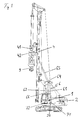
- FIG. 1 An embodiment of a construction device according to the invention, which is exemplified as a drill, is in Fig. 1 shown.
- the construction equipment shown has a mast 4, on which a carriage 42 is guided longitudinally displaceable with a drill drive 41. On the carriage 42 with the drill drive 41 turn a trained as a drill harrow 9 is guided longitudinally displaceable.
- the mast 4 is supported by an adjustable support mechanism 6, which is arranged on a chassis 2 designed as a crawler chassis.
- the support mechanism 6 has a parallelogram kinematics with two parallel support arms 61 and 62.
- the support arm 61 is pivotable about a horizontal pivot axis 71 on Chassis 2 articulated.
- the second support arm 62 is pivotally connected to the chassis 2 about a horizontally extending second pivot axis 72.
- the two pivot axes 71 and 72 extend parallel to each other, wherein the second pivot axis 72 is disposed below the pivot axis 71 and mastizir runs.
- the two support arms 61 and 62 are articulated to a coupling element 64, on which in turn the mast 4 is pivotally provided.
- the coupling element 64 designed as a neck cylinder 65 actuator is provided.
- a rotary encoder 1 is provided in the region of the chassis-side linkage of the first support arm, with which the pivot angle ⁇ of the support arm 61 relative to the chassis 2 can be detected.
- This swivel angle ⁇ (compare Fig. 2 ) represents a measure of the position of the support mechanism 6 and thus a measure of the adjustment position of the mast 4.
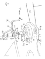
- Fig. 2 shows an enlarged sectional view of the construction equipment Fig. 1 in the area of the rotary encoder 1.
- Fig. 2 shows a center support 70 is shown, on which the first support arm 61 is articulated.
- the second support arm 62 is merely indicated.
- the chassis has two bearing plates 78, 78 ', which run parallel to one another, and between which the two support arms 61 and 62 are articulated.
- These bearing plates 78 and 78 'carry at least one in Fig. 2 only indicated axle pin 75, on which the first support arm 61 is pivotally mounted about the pivot axis 71, and at least one further, parallel pivot pin 76, on which the second support arm 62 is pivotally mounted about the pivot axis 72.
- the rotary encoder 1 is arranged coaxially on the mathematical pivot axis 71 of the mastferneren, so rear closer, upper support arm 61.
- the rotary encoder 1 is located on the side facing away from the support arm 61 outside of the bearing plate 78th
- a control unit 20 for controlling the actuator 66 and preferably also of the neck cylinder 65 is provided.
- This control unit 20 is connected to the rotary encoder 1 in preferably electrical signal connection, so that the actuator 66 and possibly also the neck cylinder 65 in dependence of the swivel angle ⁇ , which is detected by the rotary encoder 1, can be controlled, so that the mast 4 in a stable tilt Adjustment range 6 can be maintained.
- the rotary encoder 1 has an approximately cylindrical encoder housing 10, on the lateral surface of which an electrical connection 19 for angular data signals is provided. At the front end, this encoder housing 10 projects beyond an encoder shaft 11. The rotary encoder 1 is set up so that the absolute rotation of the encoder shaft 11 relative to the encoder housing 10 is output as a signal.
- the encoder shaft 11 and the cylindrical encoder housing 10 are arranged coaxially to the pivot axis 71 on the outside of the bearing plate 78 for the support arm 61, so that the encoder shaft 11 protrudes perpendicularly from the bearing plate 78.
- a cover 21 is present for rotationally fixed fixing of the encoder housing 10 on the bearing plate 78 and thus on the chassis 2.
- this cover 21 has a cylindrical holding portion 23.
- the encoder housing 10 can be fixed in rotation on a flag 81 with radially projecting nose 82 via frontally arranged screws 29.
- the screws 29 thereby surround an end-side passage opening 28 in the cover 21, which serves for the passage of the encoder shaft 11.
- the nose 82 engages in a U-shaped receptacle 83, which is arranged on a holding plate 84 which is fixed to the bearing plate 78 in a defined position.
- a concentric with the pivot axis 71 arranged bolt 80 penetrates the flag 81 and the support plate 82 and communicates with the axle 75 in connection.
- an outer diameter larger flange portion 24 adjoins the holding portion 23 of the cover 21 coaxially.
- These holes 22 are arranged with an asymmetrical hole pattern, so that the position of the cover 21 relative to the chassis 2 is clearly fixed.
- an asymmetrical hole pattern can also be provided for the screws 29.
- a sector-shaped recess 26 which extends through both the holding portion 23 and the flange portion 24, and allows access to the terminal 19.
- the encoder shaft 11 is rotatably coupled via an actuating bracket 30 with the support arm 61.
- This actuating bracket 30 is attached at its one end by means of a bolt 51 on the support arm 61.
- the bracket 30 is rotatably connected by means of a bolt 52 with the encoder shaft 11.
- the bolt 52 extends transversely through a mounting sleeve 53, which is arranged for mechanical reinforcement on the bracket 30, and which serves to receive the encoder shaft 11.
- a corresponding, transverse hole 54 is provided, through which the bolt 52 is inserted for a rotationally fixed connection.
- the otherwise cylindrical encoder shaft 11 has a flattening 12 in its lateral surface, wherein a projection may be provided in the fastening sleeve 53, which projection corresponds to the flattening 12.
- the actuating bracket 30 is formed with a two-step profile, which simulates the contour of the bearing plate 78 and the cover 21.
- This two-step profile is formed by first stage for adaptation to the bearing plate 78, which is formed at right angles, and by a second stage for adaptation to the cover 21, which is formed obliquely.
Landscapes
- Engineering & Computer Science (AREA)
- Mining & Mineral Resources (AREA)
- Life Sciences & Earth Sciences (AREA)
- Geology (AREA)
- Structural Engineering (AREA)
- General Engineering & Computer Science (AREA)
- Civil Engineering (AREA)
- Mechanical Engineering (AREA)
- General Life Sciences & Earth Sciences (AREA)
- Physics & Mathematics (AREA)
- Environmental & Geological Engineering (AREA)
- Fluid Mechanics (AREA)
- Geochemistry & Mineralogy (AREA)
- Paleontology (AREA)
- Buildings Adapted To Withstand Abnormal External Influences (AREA)
- Earth Drilling (AREA)
- Component Parts Of Construction Machinery (AREA)
- Foundations (AREA)
- Consolidation Of Soil By Introduction Of Solidifying Substances Into Soil (AREA)
- Manipulator (AREA)
- Length Measuring Devices With Unspecified Measuring Means (AREA)
Priority Applications (6)
| Application Number | Priority Date | Filing Date | Title |
|---|---|---|---|
| ES09007945T ES2383238T3 (es) | 2009-06-17 | 2009-06-17 | Aparato de construcción para ingeniería civil |
| EP09007945A EP2275604B1 (fr) | 2009-06-17 | 2009-06-17 | Engine avec une jumelle |
| AT09007945T ATE554233T1 (de) | 2009-06-17 | 2009-06-17 | Baugerät für den tiefbau |
| US12/797,199 US8483915B2 (en) | 2009-06-17 | 2010-06-09 | Construction apparatus for foundation construction |
| CN2010102116771A CN101929157B (zh) | 2009-06-17 | 2010-06-17 | 用于基础建筑的建筑设备 |
| HK11101721.1A HK1147784B (en) | 2009-06-17 | 2011-02-22 | Construction apparatus for foundation construction |
Applications Claiming Priority (1)
| Application Number | Priority Date | Filing Date | Title |
|---|---|---|---|
| EP09007945A EP2275604B1 (fr) | 2009-06-17 | 2009-06-17 | Engine avec une jumelle |
Publications (2)
| Publication Number | Publication Date |
|---|---|
| EP2275604A1 true EP2275604A1 (fr) | 2011-01-19 |
| EP2275604B1 EP2275604B1 (fr) | 2012-04-18 |
Family
ID=40904181
Family Applications (1)
| Application Number | Title | Priority Date | Filing Date |
|---|---|---|---|
| EP09007945A Active EP2275604B1 (fr) | 2009-06-17 | 2009-06-17 | Engine avec une jumelle |
Country Status (5)
| Country | Link |
|---|---|
| US (1) | US8483915B2 (fr) |
| EP (1) | EP2275604B1 (fr) |
| CN (1) | CN101929157B (fr) |
| AT (1) | ATE554233T1 (fr) |
| ES (1) | ES2383238T3 (fr) |
Cited By (7)
| Publication number | Priority date | Publication date | Assignee | Title |
|---|---|---|---|---|
| CN103061672A (zh) * | 2011-10-19 | 2013-04-24 | 包尔机械有限公司 | 施工设备 |
| EP2639357A1 (fr) * | 2012-03-15 | 2013-09-18 | BAUER Maschinen GmbH | Engin et son procédé de fonctionnement |
| ITTV20130049A1 (it) * | 2013-04-11 | 2014-10-12 | Renzo Porcellato | Macchina da palificazione |
| EP2918728A1 (fr) * | 2014-03-13 | 2015-09-16 | Soilmec S.p.A. | Dispositif d'entraînement profond de tubes ayant un grand diamètre |
| WO2017174862A1 (fr) * | 2016-04-08 | 2017-10-12 | Junttan Oy | Batteuse de pieu |
| IT201800005795A1 (it) * | 2018-05-29 | 2019-11-29 | Metodo e sistema per l’installazione di un pozzetto per infrastrutture di reti di telecomunicazioni. | |
| EP3722512A1 (fr) | 2019-04-08 | 2020-10-14 | BAUER Maschinen GmbH | Appareil de travaux de génie civil en profondeur et son procédé de fonctionnement |
Families Citing this family (14)
| Publication number | Priority date | Publication date | Assignee | Title |
|---|---|---|---|---|
| CN102678047B (zh) * | 2011-12-21 | 2015-09-02 | 河南科技大学 | 钻机及其钻臂机构 |
| US9260919B2 (en) * | 2012-06-21 | 2016-02-16 | Superior Energy Services—North America Services, Inc. | Method and apparatus for aligning a BOP stack and a mast |
| CN102913122A (zh) * | 2012-11-01 | 2013-02-06 | 玉柴桩工(常州)有限公司 | 全电气先导控制的下的旋挖钻机 |
| JP5988858B2 (ja) * | 2012-12-18 | 2016-09-07 | 日本車輌製造株式会社 | 杭打機 |
| CN103047394B (zh) * | 2012-12-26 | 2015-10-28 | 三一重工股份有限公司 | 旋挖钻机及其导向滑轮架装置 |
| DE102014009165B4 (de) * | 2014-06-25 | 2020-07-16 | Schwing Gmbh | Fahrbarer Großmanipulator |
| IT201800005910A1 (it) * | 2018-05-31 | 2019-12-01 | Macchina di perforazione, procedimento di assemblaggio, e kit per una macchina di perforazione. | |
| US11414929B2 (en) | 2020-03-09 | 2022-08-16 | Watson, Incorporated | Drilling apparatus and related method |
| AU2021203567A1 (en) * | 2020-06-18 | 2022-01-20 | Tusimple, Inc. | Angle and orientation measurements for vehicles with multiple drivable sections |
| EP4074937A1 (fr) * | 2021-04-12 | 2022-10-19 | Bay Shore Systems Inc. | Ensemble de fixation de chargeuse à direction à glissement et procédés permettant d'effectuer un forage à l'aide d'une chargeuse à direction à glissement |
| GB2605486B (en) * | 2021-12-16 | 2023-09-13 | Sheet Piling Uk Ltd | A pile driver |
| CN114855899B (zh) * | 2022-05-12 | 2023-06-23 | 南京工业大学 | 一种挖掘机工作阶段及工况识别方法 |
| CN115321377A (zh) * | 2022-08-29 | 2022-11-11 | 南京中船绿洲机器有限公司 | 一种船用起重机变幅编码器安装机构 |
| TR2023018277A2 (tr) * | 2023-12-25 | 2024-03-21 | Mazaka Maki̇na Sanayi̇ Ve Ti̇caret Li̇mi̇ted Şi̇rketi̇ | Enkoderli̇ asansör mekani̇zmasina sahi̇p kazik çakma maki̇nasi |
Citations (3)
| Publication number | Priority date | Publication date | Assignee | Title |
|---|---|---|---|---|
| EP0894901A2 (fr) * | 1997-07-30 | 1999-02-03 | Laser Alignment, Inc. | Commande pour un engin de chantier à entraínement hydraulique ayant de multiples membres articulés en tandem |
| DE20011371U1 (de) * | 2000-06-28 | 2000-09-14 | Bauer Spezialtiefbau Gmbh, 86529 Schrobenhausen | Bauarbeitsgerät |
| EP1717375A1 (fr) | 2005-04-29 | 2006-11-02 | BAUER Maschinen GmbH | Appareil et méthode pour presser et extraire des éléments de paroi de palplanches |
Family Cites Families (6)
| Publication number | Priority date | Publication date | Assignee | Title |
|---|---|---|---|---|
| US3665148A (en) * | 1971-04-07 | 1972-05-23 | Gen Motors Corp | Six-axis manipulator |
| EP0116474B1 (fr) * | 1983-02-12 | 1986-12-10 | Kabushiki Kaisha Hikoma Seisakusho | Engin de terrassement |
| US4688983A (en) * | 1984-05-21 | 1987-08-25 | Unimation Inc. | Low cost robot |
| JPH07187568A (ja) * | 1993-12-28 | 1995-07-25 | Komatsu Ltd | クレーンの制御装置 |
| JPH10219728A (ja) * | 1997-01-31 | 1998-08-18 | Komatsu Ltd | 建設機械の干渉防止装置 |
| CN100582685C (zh) * | 2008-03-27 | 2010-01-20 | 山西新元自动化仪表有限公司 | 装载机电子秤 |
-
2009
- 2009-06-17 EP EP09007945A patent/EP2275604B1/fr active Active
- 2009-06-17 AT AT09007945T patent/ATE554233T1/de active
- 2009-06-17 ES ES09007945T patent/ES2383238T3/es active Active
-
2010
- 2010-06-09 US US12/797,199 patent/US8483915B2/en active Active
- 2010-06-17 CN CN2010102116771A patent/CN101929157B/zh not_active Expired - Fee Related
Patent Citations (3)
| Publication number | Priority date | Publication date | Assignee | Title |
|---|---|---|---|---|
| EP0894901A2 (fr) * | 1997-07-30 | 1999-02-03 | Laser Alignment, Inc. | Commande pour un engin de chantier à entraínement hydraulique ayant de multiples membres articulés en tandem |
| DE20011371U1 (de) * | 2000-06-28 | 2000-09-14 | Bauer Spezialtiefbau Gmbh, 86529 Schrobenhausen | Bauarbeitsgerät |
| EP1717375A1 (fr) | 2005-04-29 | 2006-11-02 | BAUER Maschinen GmbH | Appareil et méthode pour presser et extraire des éléments de paroi de palplanches |
Cited By (11)
| Publication number | Priority date | Publication date | Assignee | Title |
|---|---|---|---|---|
| CN103061672A (zh) * | 2011-10-19 | 2013-04-24 | 包尔机械有限公司 | 施工设备 |
| EP2584097A1 (fr) * | 2011-10-19 | 2013-04-24 | BAUER Maschinen GmbH | Appareil de construction |
| CN103061672B (zh) * | 2011-10-19 | 2015-05-13 | 包尔机械有限公司 | 施工设备 |
| EP2639357A1 (fr) * | 2012-03-15 | 2013-09-18 | BAUER Maschinen GmbH | Engin et son procédé de fonctionnement |
| RU2536595C2 (ru) * | 2012-03-15 | 2014-12-27 | Бауэр Машинен Гмбх | Строительная машина и способ управления строительной машиной |
| ITTV20130049A1 (it) * | 2013-04-11 | 2014-10-12 | Renzo Porcellato | Macchina da palificazione |
| EP2918728A1 (fr) * | 2014-03-13 | 2015-09-16 | Soilmec S.p.A. | Dispositif d'entraînement profond de tubes ayant un grand diamètre |
| WO2017174862A1 (fr) * | 2016-04-08 | 2017-10-12 | Junttan Oy | Batteuse de pieu |
| IT201800005795A1 (it) * | 2018-05-29 | 2019-11-29 | Metodo e sistema per l’installazione di un pozzetto per infrastrutture di reti di telecomunicazioni. | |
| EP3722512A1 (fr) | 2019-04-08 | 2020-10-14 | BAUER Maschinen GmbH | Appareil de travaux de génie civil en profondeur et son procédé de fonctionnement |
| US12110778B2 (en) | 2019-04-08 | 2024-10-08 | Bauer Maschinen Gmbh | Civil engineering underground equipment and method for operating civil engineering underground equipment |
Also Published As
| Publication number | Publication date |
|---|---|
| US8483915B2 (en) | 2013-07-09 |
| HK1147784A1 (en) | 2011-08-19 |
| CN101929157B (zh) | 2012-10-10 |
| US20100319222A1 (en) | 2010-12-23 |
| CN101929157A (zh) | 2010-12-29 |
| EP2275604B1 (fr) | 2012-04-18 |
| ES2383238T3 (es) | 2012-06-19 |
| ATE554233T1 (de) | 2012-05-15 |
Similar Documents
| Publication | Publication Date | Title |
|---|---|---|
| EP2275604B1 (fr) | Engine avec une jumelle | |
| EP3255239B1 (fr) | Engin doté d'une unité de calcul pour déterminer une zone de réglage | |
| EP2028153B1 (fr) | Treuil | |
| DE102014118626A1 (de) | Bohrgerät | |
| DE102012021191B4 (de) | Lader | |
| EP2728073B1 (fr) | Chargeur | |
| DE69922668T2 (de) | Auslegeranordnung für eine gesteinbohreinheit | |
| DE102012021379A1 (de) | Bodenfräsmaschine mit schwenkbarer Fahreinrichtung | |
| EP3075246A1 (fr) | Machine agricole et procede de securite | |
| WO2009112236A1 (fr) | Grue à chenilles, ainsi que procédé de réglage d'une position de manœuvre au sol d'une grue à chenilles de ce type | |
| DE2821113A1 (de) | Verfahren und vorrichtung zur maschinellen einstellung der neigung einer gesteinsbohrvorrichtung | |
| EP3831187B1 (fr) | Appareil de travail à bras porteur, engin de travail autonome doté d'un tel appareil et procédé de détection des charges agissant sur le bras porteur | |
| EP1655415A1 (fr) | Machine de travaux de construction avec mât et poulie réglable | |
| DE69520556T2 (de) | Vorrichtung zur Detektion der Verschiebung sich bewegender Teile in industriellen Apparaten | |
| EP3658311A1 (fr) | Installation de traitement d'éléments structuraux d'aéronef | |
| EP1466862B1 (fr) | Système et procédé de nivellement pour une nacelle d'une nacelle élévatrice | |
| EP2101145B1 (fr) | Appareil de mesure et procédé de détection de l'état d'usure de forages d'extrudeuses à vis sans fin | |
| EP0438660A2 (fr) | Dispositif pour mesurer des forces s'exercant latéralement | |
| DE10131559A1 (de) | Vorrichtung zur Bodendruckentlastung von am Erdboden arbeitenden Arbeitsgeräten | |
| EP3404197A1 (fr) | Dispositif de forage et procédé de vissage d'éléments de tiges de forage comprenant un dispositif de forage | |
| EP3584370B1 (fr) | Engin de chantier et procédé de fonctionnement d'un engin de chantier | |
| EP2236733B1 (fr) | Unité d'entraînement pour un appareil de forage ou de construction | |
| EP4063568B1 (fr) | Dispositif de mesure et dispositif d'enlèvement doté d'un dispositif de mesure | |
| EP2584097B1 (fr) | Appareil de construction | |
| DE60105530T2 (de) | Steuereinrichtung der räumlichen Position der Achseneinheit eines Nutzfahrzeugs |
Legal Events
| Date | Code | Title | Description |
|---|---|---|---|
| PUAI | Public reference made under article 153(3) epc to a published international application that has entered the european phase |
Free format text: ORIGINAL CODE: 0009012 |
|
| 17P | Request for examination filed |
Effective date: 20090922 |
|
| AK | Designated contracting states |
Kind code of ref document: A1 Designated state(s): AT BE BG CH CY CZ DE DK EE ES FI FR GB GR HR HU IE IS IT LI LT LU LV MC MK MT NL NO PL PT RO SE SI SK TR |
|
| AX | Request for extension of the european patent |
Extension state: AL BA RS |
|
| RIN1 | Information on inventor provided before grant (corrected) |
Inventor name: LANZL, MARTIN, DIPL.-ING. Inventor name: OSTERMEIER, MANUEL PETER Inventor name: MAYR, MARKUS, DIPL.-ING. Inventor name: SCHNITZLER, STEFAN, DIPL.-ING. |
|
| RTI1 | Title (correction) |
Free format text: MACHINE WITH SCAFFOLD |
|
| GRAP | Despatch of communication of intention to grant a patent |
Free format text: ORIGINAL CODE: EPIDOSNIGR1 |
|
| RAP1 | Party data changed (applicant data changed or rights of an application transferred) |
Owner name: BAUER MASCHINEN GMBH |
|
| GRAS | Grant fee paid |
Free format text: ORIGINAL CODE: EPIDOSNIGR3 |
|
| GRAA | (expected) grant |
Free format text: ORIGINAL CODE: 0009210 |
|
| AK | Designated contracting states |
Kind code of ref document: B1 Designated state(s): AT BE BG CH CY CZ DE DK EE ES FI FR GB GR HR HU IE IS IT LI LT LU LV MC MK MT NL NO PL PT RO SE SI SK TR |
|
| REG | Reference to a national code |
Ref country code: GB Ref legal event code: FG4D Free format text: NOT ENGLISH |
|
| REG | Reference to a national code |
Ref country code: CH Ref legal event code: EP |
|
| REG | Reference to a national code |
Ref country code: IE Ref legal event code: FG4D Free format text: LANGUAGE OF EP DOCUMENT: GERMAN |
|
| REG | Reference to a national code |
Ref country code: AT Ref legal event code: REF Ref document number: 554233 Country of ref document: AT Kind code of ref document: T Effective date: 20120515 |
|
| REG | Reference to a national code |
Ref country code: DE Ref legal event code: R096 Ref document number: 502009003249 Country of ref document: DE Effective date: 20120614 |
|
| REG | Reference to a national code |
Ref country code: ES Ref legal event code: FG2A Ref document number: 2383238 Country of ref document: ES Kind code of ref document: T3 Effective date: 20120619 |
|
| REG | Reference to a national code |
Ref country code: NL Ref legal event code: T3 |
|
| LTIE | Lt: invalidation of european patent or patent extension |
Effective date: 20120418 |
|
| PG25 | Lapsed in a contracting state [announced via postgrant information from national office to epo] |
Ref country code: SE Free format text: LAPSE BECAUSE OF FAILURE TO SUBMIT A TRANSLATION OF THE DESCRIPTION OR TO PAY THE FEE WITHIN THE PRESCRIBED TIME-LIMIT Effective date: 20120418 Ref country code: LT Free format text: LAPSE BECAUSE OF FAILURE TO SUBMIT A TRANSLATION OF THE DESCRIPTION OR TO PAY THE FEE WITHIN THE PRESCRIBED TIME-LIMIT Effective date: 20120418 Ref country code: CY Free format text: LAPSE BECAUSE OF FAILURE TO SUBMIT A TRANSLATION OF THE DESCRIPTION OR TO PAY THE FEE WITHIN THE PRESCRIBED TIME-LIMIT Effective date: 20120418 Ref country code: NO Free format text: LAPSE BECAUSE OF FAILURE TO SUBMIT A TRANSLATION OF THE DESCRIPTION OR TO PAY THE FEE WITHIN THE PRESCRIBED TIME-LIMIT Effective date: 20120718 Ref country code: FI Free format text: LAPSE BECAUSE OF FAILURE TO SUBMIT A TRANSLATION OF THE DESCRIPTION OR TO PAY THE FEE WITHIN THE PRESCRIBED TIME-LIMIT Effective date: 20120418 Ref country code: PL Free format text: LAPSE BECAUSE OF FAILURE TO SUBMIT A TRANSLATION OF THE DESCRIPTION OR TO PAY THE FEE WITHIN THE PRESCRIBED TIME-LIMIT Effective date: 20120418 Ref country code: IS Free format text: LAPSE BECAUSE OF FAILURE TO SUBMIT A TRANSLATION OF THE DESCRIPTION OR TO PAY THE FEE WITHIN THE PRESCRIBED TIME-LIMIT Effective date: 20120818 |
|
| PG25 | Lapsed in a contracting state [announced via postgrant information from national office to epo] |
Ref country code: SI Free format text: LAPSE BECAUSE OF FAILURE TO SUBMIT A TRANSLATION OF THE DESCRIPTION OR TO PAY THE FEE WITHIN THE PRESCRIBED TIME-LIMIT Effective date: 20120418 Ref country code: GR Free format text: LAPSE BECAUSE OF FAILURE TO SUBMIT A TRANSLATION OF THE DESCRIPTION OR TO PAY THE FEE WITHIN THE PRESCRIBED TIME-LIMIT Effective date: 20120719 Ref country code: HR Free format text: LAPSE BECAUSE OF FAILURE TO SUBMIT A TRANSLATION OF THE DESCRIPTION OR TO PAY THE FEE WITHIN THE PRESCRIBED TIME-LIMIT Effective date: 20120418 Ref country code: LV Free format text: LAPSE BECAUSE OF FAILURE TO SUBMIT A TRANSLATION OF THE DESCRIPTION OR TO PAY THE FEE WITHIN THE PRESCRIBED TIME-LIMIT Effective date: 20120418 Ref country code: PT Free format text: LAPSE BECAUSE OF FAILURE TO SUBMIT A TRANSLATION OF THE DESCRIPTION OR TO PAY THE FEE WITHIN THE PRESCRIBED TIME-LIMIT Effective date: 20120820 |
|
| BERE | Be: lapsed |
Owner name: BAUER MASCHINEN G.M.B.H. Effective date: 20120630 |
|
| PG25 | Lapsed in a contracting state [announced via postgrant information from national office to epo] |
Ref country code: CZ Free format text: LAPSE BECAUSE OF FAILURE TO SUBMIT A TRANSLATION OF THE DESCRIPTION OR TO PAY THE FEE WITHIN THE PRESCRIBED TIME-LIMIT Effective date: 20120418 Ref country code: EE Free format text: LAPSE BECAUSE OF FAILURE TO SUBMIT A TRANSLATION OF THE DESCRIPTION OR TO PAY THE FEE WITHIN THE PRESCRIBED TIME-LIMIT Effective date: 20120418 Ref country code: RO Free format text: LAPSE BECAUSE OF FAILURE TO SUBMIT A TRANSLATION OF THE DESCRIPTION OR TO PAY THE FEE WITHIN THE PRESCRIBED TIME-LIMIT Effective date: 20120418 Ref country code: SK Free format text: LAPSE BECAUSE OF FAILURE TO SUBMIT A TRANSLATION OF THE DESCRIPTION OR TO PAY THE FEE WITHIN THE PRESCRIBED TIME-LIMIT Effective date: 20120418 Ref country code: DK Free format text: LAPSE BECAUSE OF FAILURE TO SUBMIT A TRANSLATION OF THE DESCRIPTION OR TO PAY THE FEE WITHIN THE PRESCRIBED TIME-LIMIT Effective date: 20120418 Ref country code: MC Free format text: LAPSE BECAUSE OF NON-PAYMENT OF DUE FEES Effective date: 20120630 |
|
| PLBE | No opposition filed within time limit |
Free format text: ORIGINAL CODE: 0009261 |
|
| STAA | Information on the status of an ep patent application or granted ep patent |
Free format text: STATUS: NO OPPOSITION FILED WITHIN TIME LIMIT |
|
| PG25 | Lapsed in a contracting state [announced via postgrant information from national office to epo] |
Ref country code: MK Free format text: LAPSE BECAUSE OF FAILURE TO SUBMIT A TRANSLATION OF THE DESCRIPTION OR TO PAY THE FEE WITHIN THE PRESCRIBED TIME-LIMIT Effective date: 20120418 |
|
| 26N | No opposition filed |
Effective date: 20130121 |
|
| REG | Reference to a national code |
Ref country code: IE Ref legal event code: MM4A |
|
| PG25 | Lapsed in a contracting state [announced via postgrant information from national office to epo] |
Ref country code: BE Free format text: LAPSE BECAUSE OF NON-PAYMENT OF DUE FEES Effective date: 20120630 Ref country code: IE Free format text: LAPSE BECAUSE OF NON-PAYMENT OF DUE FEES Effective date: 20120617 |
|
| REG | Reference to a national code |
Ref country code: DE Ref legal event code: R097 Ref document number: 502009003249 Country of ref document: DE Effective date: 20130121 |
|
| PG25 | Lapsed in a contracting state [announced via postgrant information from national office to epo] |
Ref country code: BG Free format text: LAPSE BECAUSE OF FAILURE TO SUBMIT A TRANSLATION OF THE DESCRIPTION OR TO PAY THE FEE WITHIN THE PRESCRIBED TIME-LIMIT Effective date: 20120718 Ref country code: MT Free format text: LAPSE BECAUSE OF FAILURE TO SUBMIT A TRANSLATION OF THE DESCRIPTION OR TO PAY THE FEE WITHIN THE PRESCRIBED TIME-LIMIT Effective date: 20120418 |
|
| REG | Reference to a national code |
Ref country code: CH Ref legal event code: PL |
|
| PG25 | Lapsed in a contracting state [announced via postgrant information from national office to epo] |
Ref country code: TR Free format text: LAPSE BECAUSE OF FAILURE TO SUBMIT A TRANSLATION OF THE DESCRIPTION OR TO PAY THE FEE WITHIN THE PRESCRIBED TIME-LIMIT Effective date: 20120418 Ref country code: LI Free format text: LAPSE BECAUSE OF NON-PAYMENT OF DUE FEES Effective date: 20130630 Ref country code: CH Free format text: LAPSE BECAUSE OF NON-PAYMENT OF DUE FEES Effective date: 20130630 |
|
| PG25 | Lapsed in a contracting state [announced via postgrant information from national office to epo] |
Ref country code: LU Free format text: LAPSE BECAUSE OF NON-PAYMENT OF DUE FEES Effective date: 20120617 |
|
| PG25 | Lapsed in a contracting state [announced via postgrant information from national office to epo] |
Ref country code: HU Free format text: LAPSE BECAUSE OF FAILURE TO SUBMIT A TRANSLATION OF THE DESCRIPTION OR TO PAY THE FEE WITHIN THE PRESCRIBED TIME-LIMIT Effective date: 20090617 |
|
| REG | Reference to a national code |
Ref country code: FR Ref legal event code: PLFP Year of fee payment: 7 |
|
| PGFP | Annual fee paid to national office [announced via postgrant information from national office to epo] |
Ref country code: ES Payment date: 20150616 Year of fee payment: 7 Ref country code: GB Payment date: 20150603 Year of fee payment: 7 |
|
| PGFP | Annual fee paid to national office [announced via postgrant information from national office to epo] |
Ref country code: FR Payment date: 20150611 Year of fee payment: 7 Ref country code: NL Payment date: 20150618 Year of fee payment: 7 |
|
| REG | Reference to a national code |
Ref country code: NL Ref legal event code: MM Effective date: 20160701 |
|
| GBPC | Gb: european patent ceased through non-payment of renewal fee |
Effective date: 20160617 |
|
| REG | Reference to a national code |
Ref country code: FR Ref legal event code: ST Effective date: 20170228 |
|
| PG25 | Lapsed in a contracting state [announced via postgrant information from national office to epo] |
Ref country code: FR Free format text: LAPSE BECAUSE OF NON-PAYMENT OF DUE FEES Effective date: 20160630 |
|
| PG25 | Lapsed in a contracting state [announced via postgrant information from national office to epo] |
Ref country code: GB Free format text: LAPSE BECAUSE OF NON-PAYMENT OF DUE FEES Effective date: 20160617 Ref country code: NL Free format text: LAPSE BECAUSE OF NON-PAYMENT OF DUE FEES Effective date: 20160701 |
|
| REG | Reference to a national code |
Ref country code: DE Ref legal event code: R082 Ref document number: 502009003249 Country of ref document: DE Representative=s name: WUNDERLICH & HEIM PATENTANWAELTE PARTNERSCHAFT, DE |
|
| PG25 | Lapsed in a contracting state [announced via postgrant information from national office to epo] |
Ref country code: ES Free format text: LAPSE BECAUSE OF NON-PAYMENT OF DUE FEES Effective date: 20160618 |
|
| REG | Reference to a national code |
Ref country code: ES Ref legal event code: FD2A Effective date: 20180627 |
|
| P01 | Opt-out of the competence of the unified patent court (upc) registered |
Effective date: 20230510 |
|
| PGFP | Annual fee paid to national office [announced via postgrant information from national office to epo] |
Ref country code: DE Payment date: 20250623 Year of fee payment: 17 |
|
| PGFP | Annual fee paid to national office [announced via postgrant information from national office to epo] |
Ref country code: AT Payment date: 20250623 Year of fee payment: 17 |
|
| PGFP | Annual fee paid to national office [announced via postgrant information from national office to epo] |
Ref country code: IT Payment date: 20250605 Year of fee payment: 17 |