EP2275718A2 - Transmission automatique - Google Patents
Transmission automatique Download PDFInfo
- Publication number
- EP2275718A2 EP2275718A2 EP10167107A EP10167107A EP2275718A2 EP 2275718 A2 EP2275718 A2 EP 2275718A2 EP 10167107 A EP10167107 A EP 10167107A EP 10167107 A EP10167107 A EP 10167107A EP 2275718 A2 EP2275718 A2 EP 2275718A2
- Authority
- EP
- European Patent Office
- Prior art keywords
- parking
- transmission
- casing
- rod
- cam
- Prior art date
- Legal status (The legal status is an assumption and is not a legal conclusion. Google has not performed a legal analysis and makes no representation as to the accuracy of the status listed.)
- Granted
Links
Images



Classifications
-
- F—MECHANICAL ENGINEERING; LIGHTING; HEATING; WEAPONS; BLASTING
- F16—ENGINEERING ELEMENTS AND UNITS; GENERAL MEASURES FOR PRODUCING AND MAINTAINING EFFECTIVE FUNCTIONING OF MACHINES OR INSTALLATIONS; THERMAL INSULATION IN GENERAL
- F16H—GEARING
- F16H63/00—Control outputs from the control unit to change-speed- or reversing-gearings for conveying rotary motion or to other devices than the final output mechanism
- F16H63/02—Final output mechanisms therefor; Actuating means for the final output mechanisms
- F16H63/30—Constructional features of the final output mechanisms
- F16H63/34—Locking or disabling mechanisms
- F16H63/3416—Parking lock mechanisms or brakes in the transmission
-
- B—PERFORMING OPERATIONS; TRANSPORTING
- B60—VEHICLES IN GENERAL
- B60T—VEHICLE BRAKE CONTROL SYSTEMS OR PARTS THEREOF; BRAKE CONTROL SYSTEMS OR PARTS THEREOF, IN GENERAL; ARRANGEMENT OF BRAKING ELEMENTS ON VEHICLES IN GENERAL; PORTABLE DEVICES FOR PREVENTING UNWANTED MOVEMENT OF VEHICLES; VEHICLE MODIFICATIONS TO FACILITATE COOLING OF BRAKES
- B60T1/00—Arrangements of braking elements, i.e. of those parts where braking effect occurs specially for vehicles
- B60T1/02—Arrangements of braking elements, i.e. of those parts where braking effect occurs specially for vehicles acting by retarding wheels
- B60T1/06—Arrangements of braking elements, i.e. of those parts where braking effect occurs specially for vehicles acting by retarding wheels acting otherwise than on tread, e.g. employing rim, drum, disc, or transmission or on double wheels
-
- F—MECHANICAL ENGINEERING; LIGHTING; HEATING; WEAPONS; BLASTING
- F16—ENGINEERING ELEMENTS AND UNITS; GENERAL MEASURES FOR PRODUCING AND MAINTAINING EFFECTIVE FUNCTIONING OF MACHINES OR INSTALLATIONS; THERMAL INSULATION IN GENERAL
- F16H—GEARING
- F16H57/00—General details of gearing
- F16H57/02—Gearboxes; Mounting gearing therein
-
- F—MECHANICAL ENGINEERING; LIGHTING; HEATING; WEAPONS; BLASTING
- F16—ENGINEERING ELEMENTS AND UNITS; GENERAL MEASURES FOR PRODUCING AND MAINTAINING EFFECTIVE FUNCTIONING OF MACHINES OR INSTALLATIONS; THERMAL INSULATION IN GENERAL
- F16H—GEARING
- F16H57/00—General details of gearing
- F16H57/02—Gearboxes; Mounting gearing therein
- F16H57/023—Mounting or installation of gears or shafts in the gearboxes, e.g. methods or means for assembly
-
- F—MECHANICAL ENGINEERING; LIGHTING; HEATING; WEAPONS; BLASTING
- F16—ENGINEERING ELEMENTS AND UNITS; GENERAL MEASURES FOR PRODUCING AND MAINTAINING EFFECTIVE FUNCTIONING OF MACHINES OR INSTALLATIONS; THERMAL INSULATION IN GENERAL
- F16H—GEARING
- F16H57/00—General details of gearing
- F16H57/02—Gearboxes; Mounting gearing therein
- F16H57/03—Gearboxes; Mounting gearing therein characterised by means for reinforcing gearboxes, e.g. ribs
-
- Y—GENERAL TAGGING OF NEW TECHNOLOGICAL DEVELOPMENTS; GENERAL TAGGING OF CROSS-SECTIONAL TECHNOLOGIES SPANNING OVER SEVERAL SECTIONS OF THE IPC; TECHNICAL SUBJECTS COVERED BY FORMER USPC CROSS-REFERENCE ART COLLECTIONS [XRACs] AND DIGESTS
- Y10—TECHNICAL SUBJECTS COVERED BY FORMER USPC
- Y10T—TECHNICAL SUBJECTS COVERED BY FORMER US CLASSIFICATION
- Y10T74/00—Machine element or mechanism
- Y10T74/21—Elements
- Y10T74/2186—Gear casings
Definitions
- the present invention relates to an automatic transmission having a parking-lock mechanism.
- an automotive automatic transmission which is configured to automatically accomplish upshifting and downshifting, employs a parking-lock mechanism installed in a transmission casing.
- the parking-lock mechanism is comprised of several internal linkages installed in the transmission casing, namely, a manual shaft, a parking-pawl-actuator rod (simply, a parking rod), a support actuator, and a parking pawl.
- the manual shaft is configured to rotate in synchronism with movement of a shift lever whose position is selectable by the driver.
- the parking rod is configured to displace in its longitudinal direction in synchronism with rotary motion of the manual shaft.
- the support actuator has a sloped face onto which a cam, attached to the tip of the parking rod, runs when a specified longitudinal displacement of the parking rod has been reached.
- the parking pawl is configured to be forced by the cam when the cam has run onto the sloped face of the support actuator, such that the parking pawl is brought into meshed-engagement with a parking-lock gear (simply, a parking gear) mounted on a transmission output shaft.
- a parking-lock gear implies, a parking gear mounted on a transmission output shaft.
- the parking-lock mechanism is accommodated in the transmission casing, which casing includes a transmission case and a converter housing integrally connected to each other to form a housing. Additionally, all of component parts, constructing the parking-lock mechanism, are installed on the transmission case.
- the parking-lock-mechanism equipped automatic transmission disclosed in JP2007-205383 also suffers from the disadvantages of a troublesome positioning of the parking-lock mechanism when installing on the transmission case, and undesirable deviations of the internal linkages constructing the parking-lock mechanism (e.g., the parking rod and the like), from their desired installation positions, in other words, the problem of the deteriorated assembly work when the transmission case and the converter housing are integrally connected to each other.
- an object of the invention to provide an automatic transmission configured to ensure decentralization of a load (a reaction force) applied from a transmission output shaft through a parking-lock mechanism to a transmission casing without high localized load application to the transmission casing in a parking range, and also configured to enable more efficient assembly work of the parking-lock-mechanism equipped automatic transmission.
- an automatic transmission comprises a parking-lock mechanism accommodated in a transmission casing, for mechanically locking and unlocking a transmission output shaft of a speed-change system by engaging and disengaging the parking-lock mechanism with and from the transmission output shaft
- the transmission casing comprises a first casing and a second casing integrally connected to each other to form a housing configured to cover the speed-change system
- the parking-lock mechanism comprises a manual shaft configured to rotate in synchronism with a driver's shift-lever operation, a parking rod whose longitudinal displacement is produced by rotary motion of the manual shaft, a support actuator onto which a cam, attached to a tip of the parking rod, runs when a specified longitudinal displacement of the parking rod has been reached, and a parking pawl configured to be pushed and moved by the cam when the cam has run onto the support actuator owing to the specified longitudinal displacement of the parking rod so that the parking pawl is brought into meshed-engagement with a parking gear installed on the transmission
- the power train carries power output from an engine 1 (a source of driving power) to road wheels 6, 6.
- the power train is comprised of a torque converter 2, an automatic transmission 3, and axle driveshafts 6a, 6a.
- Automatic transmission 3 has a driven connection with an output shaft 2a of torque converter 2.
- the power is delivered from automatic transmission 3 via axle driveshafts 6a, 6a to respective road wheels 6, 6.
- the shifting operation of automatic transmission 3 is controlled by means of a transmission control unit 7.
- Transmission control unit 7 is comprised of a continuously variable automatic transmission (CVT) control section 7a and a stepped automatic transmission (AT) control section 7b.
- CVT control section 7a is provided to control the operation of a continuously variable automatic transmission 20 (described later)
- stepped AT control section 7b is provided to control the operation of a stepped automatic transmission 30 (described later).
- a speed-change system TM and a parking-lock mechanism P are both accommodated in a transmission casing 8 of automatic transmission 3.
- Parking-lock mechanism P is installed in transmission casing 8, for mechanically locking and unlocking a transmission output shaft 4, which shaft is an output shaft of speed-change system TM, by engaging and disengaging parking-lock mechanism P with and from the transmission output shaft.
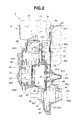
- transmission casing 8 includes a converter housing (a second casing) 8a, a transmission cover 8b, a transmission case (a first casing) 8c, and a bearing retainer (a bearing retaining wall) 8d.
- Converter housing (the second casing) 8a has a recessed portion 81a so that torque converter 2 is fitted onto the inner peripheral wall of recessed portion 81a, and forms a part of the contour of the transmission casing structure on the side of torque converter 2.
- Converter housing 8a is formed with an input-shaft insertion bore 82a and a drive-shaft insertion bore 83a.
- output shaft 2a of torque converter 2 is inserted into input-shaft insertion bore 82a, whereas one of axle driveshafts 6a, 6a (the righthand driveshaft 6a, viewing Fig. 2 ) is associated with drive-shaft insertion bore 83a in such a manner as to protrude from drive-shaft insertion bore 83a.
- Input-shaft insertion hole 82a is formed in the converter housing 8a substantially at a center of recessed portion 81a. Furthermore, an output-shaft bearing 84a is installed on converter housing 8a to rotatably support one axial portion of transmission output shaft 4.
- Transmission cover 8b is contoured so that the internal wall surface of transmission cover 8b covers both the end face (the left-hand end face, viewing Fig. 2 ) of a primary pulley 21 and the end face (the left-hand end face, viewing Fig. 2 ) of a secondary pulley 22 of continuously variable automatic transmission 20 (described later), and forms a part of the contour of transmission casing structure on the side of the continuously variable automatic transmission.
- a primary-pulley bearing 81b and a secondary-pulley bearing 82b are both installed on transmission cover 8b.
- Primary-pulley bearing 81b is provided to rotatably support primary pulley 21, whereas secondary-pulley bearing 82b is provided to rotatably support secondary pulley 22.
- a primary-pulley revolution speed sensor KS1 and a secondary-pulley revolution speed sensor KS2 are also installed on transmission cover 8b.
- Transmission case (he first casing) 8c is sandwiched between converter housing 8a and transmission cover 8b in such a manner as to form an intermediate partition wall structure by which the internal space of transmission casing 8 can be divided into two spaces.
- converter housing 8a and transmission case 8c are integrally connected to each other and additionally transmission cover 8b and transmission case 8c are integrally connected to each other, so as to form the contour of transmission casing 8 (i.e., a housing contoured to cover or protect speed-change system TM).
- a first transmission area S1 is sectioned by transmission cover 8b and transmission case 8c, so that continuously variable automatic transmission 20 is accommodated in first transmission area S1.
- a second transmission area S2 is sectioned by converter housing 8a and transmission case 8c, so that parking-lock mechanism P is accommodated in second transmission area S2.
- An input-shaft bearing 81c, a primary-pulley bearing 82c, and a secondary-pulley bearing 83c are installed on transmission case 8c.
- Input-shaft bearing 81c is provided to rotatably support the axial end of the output shaft 2a of torque converter 2.
- Primary-pulley bearing 82c is provided to rotatably support the input shaft of primary pulley 21, whereas secondary-pulley bearing 83c is provided to rotatably support the output shaft of secondary pulley 22.
- Transmission case 8c is formed with a drive-shaft insertion bore 84c.
- axle driveshafts 6a, 6a (the left-hand driveshaft 6a, viewing Fig. 2 ) is associated with drive-shaft insertion bore 84c in such a manner as to protrude from drive-shaft insertion bore 84c.
- transmission case (the first casing) 8c has a recessed portion 85c, so that stepped automatic transmission 30 is fitted onto the inner peripheral wall of recessed portion 85c.
- Secondary-pulley bearing 83c is arranged and installed on the transmission case 8c substantially at a center of recessed portion 85c.
- Bearing retainer 8d is fixedly connected to or installed on transmission case 8c in such a manner as to cover the recessed portion 85c.
- the inside of recessed portion 85c is sectioned from the second transmission area S2 by installing bearing retainer 8c on the transmission case 8c. That is, a third transmission area S3 is sectioned by both transmission case 8c and bearing retainer 8d, so that stepped automatic transmission 30 is accommodated in third transmission area S3.
- an output-shaft bearing 81d is installed on bearing retainer 8d to rotatably support another axial portion of transmission output shaft 4, whish shaft has a driven connection with stepped automatic transmission 30.
- Figs. 2 and 6A-6B an output-shaft bearing 81d is installed on bearing retainer 8d to rotatably support another axial portion of transmission output shaft 4, whish shaft has a driven connection with stepped automatic transmission 30.
- bearing retainer 8d is formed integral with a rib 82d, which is configured to protrude toward the second transmission area S2.
- rib 82d includes a circumferential rib 83d, a plurality of radial ribs 84d, and a temporary-retaining rib (a protruded portion) 85d.
- Circumferential rib 83d is configured to extend along the circumference of output-shaft bearing 81d.
- Radial ribs 84d are configured to radially extend from the circumferential rib 83d, extending along the circumference of output-shaft bearing 81d.
- Temporary-retaining rib 85d is formed integral with bearing retainer 8d so as to temporarily retain or hold a parking rod 52 (described later) during an assembling work.
- the plurality of radial ribs 84d are formed on bearing retainer 8d in such a manner as to radially extend from the circumferential rib 83d at arbitrary intervals.
- Temporary-retaining rib 85d includes (i) a first temporary-retaining rib portion 85da that is provided to temporarily retain and position one lateral portion of parking rod 52 in the transverse direction of parking rod 52 (e.g., a lower portion of parking rod 52), and (ii) a second temporary-retaining rib portion 85db that is provided to temporarily retain and position the opposite lateral portion of parking rod 52 in the transverse direction of parking rod 52 (e.g., an upper portion of parking rod 52).
- speed-change system TM includes a speed-change gear set 10, continuously variable automatic transmission (a main transmission device) 20, stepped automatic transmission (a sub-transmission device) 30, and a final drive gear unit 40.
- Speed-change gear set 10 is constructed by a drive gear 11 fixedly connected to the output shaft 2a of torque converter 2 and a driven gear 12 fixedly connected to the input shaft of primary pulley 21 of continuously variable automatic transmission 20.
- a speed-change gear ratio of speed-change gear set 10 is determined by a gear ratio between drive gear 11 and driven gear 12.
- Continuously variable automatic transmission 20 is constructed by primary pulley 21, secondary pulley 22, and a belt (e.g., a segmented steel belt) 23 wound on primary and secondary pulleys 21-22.
- the input shaft of primary pulley 21 is fixedly connected to the driven gear 12 so that power is inputted from speed-change gear set 10 to primary pulley 21.
- the output shaft of secondary pulley 22 has a driving connection with the input shaft of stepped automatic transmission 30.
- Hydraulic oil is supplied to a primary-pulley actuation cylinder of primary pulley 21 and also hydraulic oil is supplied to a secondary-pulley actuation cylinder of secondary pulley 22, such that the width of the fixed flange and the movable flange, both constructing primary pulley 21, in other words, the effective diameter of primary pulley 21, can be continuously varied by the hydraulic pressure supplied to the primary-pulley actuation cylinder, and that the width of the fixed flange and the movable flange, both constructing secondary pulley 22, in other words, the effective diameter of secondary pulley 22, can be continuously varied by the hydraulic pressure supplied to the secondary-pulley actuation cylinder. In this manner, a transmission ratio of continuously variable automatic transmission 20 is steplessly variable.
- Primary pulley 21 is rotatably supported by primary-pulley bearing 81b installed on transmission cover 8b and primary-pulley bearing 82c installed on transmission case 8c.
- Secondary pulley 22 is rotatably supported by secondary-pulley bearing 82b installed on transmission cover 8b and secondary-pulley bearing 83c installed on transmission case 8c.
- Stepped automatic transmission 30 includes a so-called Ravigneaux planetary gear system.
- a compound sun gear 31 of the Ravigneaux planetary gear system serves as an input element by drivingly connecting the secondary pulley 22 of continuously variable automatic transmission 20 to the compound sun gear 31.
- a carrier 32 of the Ravigneaux planetary gear system serves as an output element by drivingly connecting the carrier 32 to the transmission output shaft 4.
- Compound sun gear 31 is configured to be fixed to transmission casing 8 by means of a low brake (a first-speed gear selection brake) L/B, so that compound sun gear 31 is held stationary.
- Carrier 32 is configured to be drivingly connected to a ring gear 33 of the Ravigneaux planetary gear system by means of a high clutch (a second-speed gear selection clutch) H/C.
- Ring gear 33 is configured to be fixed to transmission casing 8 by means of a reverse brake R/B, so that ring gear 33 is held stationary.
- each of low brake L/B, high clutch H/C, and reverse brake R/B can be controlled depending on the sullied hydraulic pressure, in such a manner as to achieve a selected one of a forward first-speed gear, a forward second-speed gear, and a reverse first-speed gear.
- a forward first-speed gear only the low brake L/B is applied.
- the forward second-speed gear only the high clutch H/C is applied.
- the reverse first-speed gear only the reverse brake R/B is applied.
- TABLE 1 shows the relationship between the operating conditions of the clutch (i.e., high clutch H/C) and the two band brakes (i.e., low brake L/B and reverse brake R/B) and the selected gear of stepped automatic transmission 30.
- the character "O” indicates an applied state
- the character "X” indicates a released state.
- stepped automatic transmission 30 is accommodated in the third transmission area S3, which area is sectioned by transmission case 8c and bearing retainer 8d.
- Final drive gear unit 40 is constructed by a drive gear 41 and a driven gear 42.
- Drive gear 41 is installed on transmission output shaft 4, which shaft is configured to protrude from bearing retainer 8d toward the side of converter housing 8a.
- Driven gear 42 is drivingly connected to the axle driveshafts 6a, 6a associated with the respective road wheels 6, 6.
- a speed reduction ratio of final drive gear unit 40 is determined by a gear ratio between drive gear 41 and driven gear 42.
- Drive gear 41 and driven gear 42, constructing final drive gear unit 40 are arranged between converter housing 8a and transmission case 8c, and thus final drive gear unit 40 is accommodated in the second transmission area S2.
- parking-lock mechanism P includes a manual shaft 51, a parking-pawl-actuator rod (usually, abbreviated to "parking rod") 52, a support actuator 53, a parking pawl 54, and a parking-lock gear (simply, a parking gear) 55.
- parking rod usually, abbreviated to "parking rod”
- support actuator 53 a support actuator
- parking pawl 54 a parking pawl 54
- parking-lock gear (simply, a parking gear) 55.
- manual shaft 51 is rotatably installed on transmission case 8c such that manual shaft 51 extends in the vertical direction of transmission case 8c, and that the upper end of manual shaft 51 partly protrudes outside of transmission case 8c.
- a parking plate 51a is attached to the upper end of manual shaft 51. Parking plate 51a is also linked to a motion-transmission linkage 51b. That is, the upper end of manual shaft 51 is mechanically linked through parking plate 51a and motion-transmission linkage 51b to a shift lever L, such that manual shaft 51 can be rotated in synchronism with a driver's shift-lever operation.
- parking rod 52 is arranged such that the longitudinally-extending major part (the main rod portion) of parking rod 52 extends in a direction perpendicular to the axial direction of manual shaft 51 and perpendicular to the axial direction of transmission output shaft 4.
- one end (a bent end portion) of parking rod 52 is linked to a detent plate (or a detent lever) 51c fixedly connected to manual shaft 51, such that rotary motion of manual shaft 51 is converted into a longitudinal displacement of parking rod 52 via detent plate 51c.
- a detent-roller-and-spring assembly (simply, a detent spring) 51d is installed on transmission case 8c by means of an attaching bolt N1.
- Detent plate 51c has a toothed portion partly formed on its outer periphery and configured by a plurality of recesses (tooth spaces) and projections. Each of the peripheral recesses of detent plate 51c is configured to be engaged with or disengaged from the roller of detent-roller-and-spring assembly 51d.
- a substantially conical-nosed cylindrical-hollow cam 56 is slidably fitted onto the other rod end (the tip) 52a of parking rod 52.
- Cam 56 is shaped at its tip into a frusto-conical shape whose diameter gradually decreasing toward the top face.
- Cam 56 is permanently forced toward the tip 52a of parking rod 52 by a spring 56a.
- Spring 56a is a compression coil spring, which is interleaved, under preload, between the bottom face of cam 56 and a parking-rod spring-retainer (not shown), put in place near the intermediate two-step bent portion of parking rod 52.
- cam 56 in order to prevent cam 56 from slipping through the tip 52a of parking rod 52, the rightmost movement (viewing Fig. 4 ) of cam 56 is restricted by means of a fastener attached to the tip of parking rod 52.
- support actuator 53 has a guide face for supporting and guiding the cam 56.
- the guide face of support actuator 53 contains a sloped face 53a onto which cam 56, attached to the tip 52a of parking rod 52, runs when a specified longitudinal displacement of parking rod 52 has been reached.
- support actuator 53 is installed on converter housing 8a by means of attaching bolts N3, N3.
- parking pawl 54 is arranged above parking gear 55 in such a manner as to circumferentially extend along the outer peripheral surface of parking gear 55.
- parking pawl 54 is arranged in a space defined between converter housing 8a and a retainer plate 54a, which plate is installed on converter housing 8a by means of two attaching bolts N2, N2, such that a central pivot 54b, integrally connected to or formed integral with the central portion of parking pawl 54, is pivotably linked to the center of retainer plate 54a.
- N2, N2 two attaching bolts
- parking pawl 54 is formed at one end with a cam-follower portion 54c, which is brought into cam-connection with cam 56, when the specified longitudinal displacement of parking rod 52 has been reached.
- parking pawl 54 is formed at the other end with a pawl 54d, which is engageable with or disengageable from parking gear 55.
- the cam-operated parking pawl 54 is permanently forced by means of a return spring 54e in an anticlockwise direction (viewing Fig. 3B ) that pawl 54d is disengaged from parking gear 55.
- a stopper 57 is installed on converter housing 8a by means of a bolt (a fastening device) 57a.
- Stopper 57 is made of an annular steel plate.
- the initial position of parking pawl 54 (in other words, the initial attitude of parking pawl 54 without pivotal force applied through cam 56 to cam-follower portion 54c of parking pawl 54 against the spring force of return spring 54e), is restricted depending on the outside diameter of the annular stopper 57 (see Fig. 3B ). More concretely, the anticlockwise rotary motion of parking pawl 54 is restricted by abutment between the backface of pawl 54d and the circumference of stopper 57. At the initial position shown in Fig. 5 , the initial attitude of parking pawl 54 is held in a state where a slight clearance space exists between support actuator 53 and cam-follower portion 54c.
- the greater the outside diameter of stopper 57 the smaller the amount of pivotal motion of parking pawl 54 (in other words, the shorter the distance between pawl 54d and parking gear 55), during a ratchet action.
- parking gear 55 is fixedly connected to a shaft section of transmission output shaft 4, axially protruded from bearing retainer 8d, such that parking gear 55 is arranged between drive gear 41 of final drive gear unit 40 and converter housing 8a.
- parking-lock mechanism P operates as follows.
- parking gear 55 is arranged between converter housing 8a and bearing retainer 8d (see Fig. 2 ), manual shaft 51 and parking rod 52 are supported by transmission case 8c (see Fig. 3A ), and support actuator 53 and parking pawl 54 are installed on converter housing 8a (see Fig. 3B ).
- parking-lock mechanism P is arranged in the second transmission area S2, which area is sectioned by converter housing 8a and transmission case 8c.
- reference sign 70 denotes an oil pump
- reference sign 71 denotes a valve control unit
- reference sign 72 denotes an oil pan.
- oil pump 70 has a driven connection with the output shaft 2a of torque converter 2 through a chain CH, such that oil pump 70 is driven by rotation of torque-converter output shaft 2a.
- transmission output shaft 4 is going to rotate, but rotary motion of transmission output shaft 4 is prevented by meshed-engagement between parking pawl 54 and parking gear 55.
- a reaction force from transmission output shaft 4 acts on each of parking pawl 54, parking rod 52 whose tip is kept in cam-connection with the cam-follower portion 54c of parking pawl 54, and support actuator 53 having the sloped face 53a onto which cam 56 of parking rod 52 runs.
- parking pawl 54 is arranged in a space defined between converter housing 8a and retainer plate 54a, which plate is installed on converter housing 8a by means of two attaching bolts N2, N2 (see Fig. 3B ).
- Support actuator 53 is installed on converter housing 8a by means of attaching bolts N3, N3 (see Fig. 3B ).
- parking rod 52 is linked to the detent plate (the detent lever) 51c fixedly connected to manual shaft 51, which shaft is rotatably installed on transmission case 8c (see Fig. 3A ).
- reaction force acting on parking pawl 54 and the reaction force acting on support actuator 53 can be supported by converter housing 8a, whereas the reaction force acting on parking rod 52 and the reaction force acting on manual haft 51 can be supported by transmission case 8c.
- the reaction force from transmission output shaft 4 can be decentralizedly supported by converter housing 8a and transmission case 8c both constructing major parts of transmission casing 8.
- continuously variable automatic transmission 20 is assembled such that the axis of the pulley shaft of primary pulley 21 and the axis of the pulley shaft of secondary pulley 22 are put up vertically with respect to transmission cover 8b.
- transmission case 8c is integrally connected to transmission cover 8b in such a manner as to cover continuously variable automatic transmission 20, and whereby the first transmission area S1 is sectioned. Then, under the condition where the axes of primary and secondary pulleys 21-22 are put up vertically, stepped automatic transmission 30 is assembled and installed on transmission case 8c. At this time, oil pump 70 and valve control unit 71 are installed on transmission case 8c.
- bearing retainer 8d is integrally connected to transmission case 8c in such a manner as to cover stepped automatic transmission 30, and whereby the third transmission area S3 is sectioned. Then, under the condition where the axes of primary and secondary pulleys 21-22 are put up vertically, transmission output shaft 4 and speed-change gear set 10 are assembled and installed. Hereupon, before installing transmission output shaft 4, drive gear 41 of final drive gear unit 40 and parking gear 55 are both pre-installed on transmission output shaft 4.
- converter housing 8a is integrally connected to transmission case 8c in such a manner as to cover transmission output shaft 4 and speed-change gear set 10, so as to form the contour of transmission casing 8 (i.e., a housing contoured to cover or protect speed-change system TM). In this manner, the assembly work of automatic transmission 3 terminates.
- parking rod 52 (exactly, cam 56 attached to the tip of parking rod 52) can be temporarily retained such that a first lateral portion of cam 56 of parking rod 52 in the transverse direction of parking rod 52 (e.g., a lower portion of cam 56, facing parking gear 55) is positioned by way of abutment between the first lateral portion of cam 56 and the first temporary-retaining rib portion 85da and that a second lateral portion of cam 56 of parking rod 52 in the transverse direction of parking rod 52 (e.g., an upper portion of cam 56, facing parking pawl 54) is positioned by way of abutment between the second lateral portion of cam 56 and the second temporary-retaining rib portion 85db. Consequently, parking rod 52 (exactly, cam 56 attached to the tip of parking rod 52) can be temporarily retained between the first temporary-retaining rib portion 85da and the second temporary-retaining rib portion 85db, when assembling.
- a first lateral portion of cam 56 of parking rod 52 in the transverse direction of parking rod 52 e
- the detent-roller-and-spring assembly (simply, the detent spring) 51d is installed on transmission case 8c by means of attaching bolt N1.
- support actuator 53 is preinstalled on converter housing 8a by means of attaching bolts N3, N3, and the central pivot 54b of parking pawl 54 is pivotably installed on the center of retainer plate 54a, which plate is installed on converter housing 8a by means of two attaching bolts N2, N2. Furthermore, stopper 57 is installed on converter housing 8a by means of bolt 57a.
- converter housing 8a is fixedly connected to converter case 8c, while mutually positioning the parking rod 52, support actuator 53, and parking pawl 54 such that the tip (the cam-equipped end) of parking rod 52, which rod is installed on transmission case 8c, enters or squeezes between support actuator 53 and parking pawl 54, both installed on converter housing 8a.
- cam 56 of parking rod 52 can be temporarily retained between the first temporary-retaining rib portion 85da and the second temporary-retaining rib portion 85db.
- the provision of the first and second temporary-retaining rib portions 85da-85db ensures easy and accurate positioning among parking rod 52, support actuator 53, and parking pawl 54.
- the internal space of transmission casing 8 is sectioned into three sections, namely, (i) the first transmission area S1 in which continuously variable automatic transmission (serving as the main transmission device) 20 is accommodated, (ii) the second transmission area S2 in which parking-lock mechanism P is accommodated, and (iii) the third transmission area S3 in which stepped automatic transmission (serving as the sub-transmission device) 30 is accommodated.
- stepped automatic transmission 30 is further installed or laid out between continuously variable automatic transmission 20 and transmission output shaft 4.
- This enables decreased outside diameters of primary and secondary pulleys 21-22 (that is, lightening and downsizing and of continuously variable automatic transmission 20), and a wider applicable gear ratio range (a wider ratio coverage) of speed-change system TM.
- it is possible to reconcile two contradictory requirements, that is, improved fuel economy and superior accelerating ability from standstill of the automotive vehicle.
- temporary-retaining rib 85d includes (i) a first temporary-retaining rib portion 85da that is provided to temporarily retain one lateral portion of parking rod 52 in the transverse direction of parking rod 52 (e.g., a lower portion of parking rod 52), and (ii) a second temporary-retaining rib portion 85db that is provided to temporarily retain the opposite lateral portion of parking rod 52 in the transverse direction of parking rod 52 (e.g., an upper portion of parking rod 52).
- Cam 56 of parking rod 52 can be temporarily retained between the first temporary-retaining rib portion 85da and the second temporary-retaining rib portion 85db, when assembling.
- the initial position of parking pawl 54 (in other words, the initial attitude of parking pawl 54 without pivotal force applied through cam 56 to cam-follower portion 54c of parking pawl 54 against the spring force of return spring 54e) is restricted by means of stopper 57 installed on converter housing 8a, such that, at the initial position, cam-follower portion 54c of parking pawl 54 is kept out of abutted-engagement with support actuator 53.
- parking pawl 54 moves out of mesh with parking gear 55 during a ratchet action with parking gear 55 disengaging from parking pawl 54 when a change of the shift-lever position is occurring, for instance, when the shift-lever position is shifting from a P (parking) range to a D (drive) range and thus parking pawl 54 returns to its initial position, parking pawl 54 never abuts on support actuator 53.
- support actuator 53 there is no necessity of a parking-pawl receiving face to be formed on support actuator 53.
- shape and dimensions of support actuator 53 can be generally simplified and downsized. This also contributes to downsizing of attaching bolts N3, N3 used to install support actuator 53 on converter housing 8a.
- stopper 57 is provided as a separate component part separated from converter housing 8a constructing a part of transmission casing 8, and thus installed on or integrally connected to converter housing 8a by means of bolt 57a. That is, stopper 57 is integrally connected to converter housing 8a, but not formed integral with converter housing 8a in a manner so as to protrude from the inner peripheral wall of converter housing 8a.
- converter housing 8a is formed by aluminum alloy casting, and a parking-pawl stopper is formed integral with converter housing 8a.
- a parking-pawl stopper is formed integral with converter housing 8a.
- stopper 57 is provided as a separate component part separated from converter housing 8a, and thus it is possible to inexpensively enhance the mechanical strength of stopper 57, and also to inexpensively suppress the occurrence of transmission-casing contaminants.
- the distance between pawl 54d of parking pawl 54 and parking gear 55 at the initial position of parking pawl 54 can be set or determined depending on the outside diameter of stopper 57.
- This distance between parking pawl 54 and parking gear 55 greatly correlates with the rotational speed of parking pawl 54 when parking pawl 54 moves into mesh with parking gear 55.
- parking-lock mechanism P is configured such that the backface of pawl 54d of parking pawl 54 is kept in abutted-engagement with the circumference of the annular stopper 57 at the initial position of parking pawl 54.
- the shape of pawl 54d is configured to ensure or have enough strength to endure for applied stresses produced every meshing actions between parking pawl 54 and parking gear 55 without breaking.
- Automatic transmission 3 of the embodiment can provide the following effects.
- temporary-retaining rib 85d is integrally formed on the bearing retainer 8d.
- a recessed structure may be further configured or provided on a portion of converter housing 8a, facing the temporary-retaining rib 85d of bearing retainer 8d, so that cam 56 as well as the tip of parking rod 52 can be partly accommodated or guided or retained in the recessed structure of converter housing 8a.
- parking rod 52 is partly surrounded by means of both the recessed structure of converter housing 8a and temporary-retaining rib 85d of bearing retainer 8d.
- the longitudinal displacement of parking rod 52 can be accurately guided by means of the recessed structure of converter housing 8a as well as temporary-retaining rib 85d of bearing retainer 8d.
- parking rod 52 can be reliably guided and displaced without deviating the parking rod 52 from the support actuator 53, thus ensuring stable pushing action of cam 56 of parking rod 52 on cam-follower portion 54c of parking pawl 54.
- a temporary-retaining structure for temporarily retaining the parking rod 52
- a ribbed structure i.e., temporary-retaining rib 85d
- a recessed structure may be formed in bearing retainer 8d so that cam 56 as well as the tip of parking rod 52 can be temporarily retained and positioned by the recessed structure of bearing retainer 8d, when installing converter housing 8a on transmission case 8c.
Landscapes
- Engineering & Computer Science (AREA)
- General Engineering & Computer Science (AREA)
- Mechanical Engineering (AREA)
- Transportation (AREA)
- Gear-Shifting Mechanisms (AREA)
- General Details Of Gearings (AREA)
Applications Claiming Priority (1)
| Application Number | Priority Date | Filing Date | Title |
|---|---|---|---|
| JP2009166442A JP4861455B2 (ja) | 2009-07-15 | 2009-07-15 | 自動変速機 |
Publications (3)
| Publication Number | Publication Date |
|---|---|
| EP2275718A2 true EP2275718A2 (fr) | 2011-01-19 |
| EP2275718A3 EP2275718A3 (fr) | 2011-12-07 |
| EP2275718B1 EP2275718B1 (fr) | 2013-03-13 |
Family
ID=42717080
Family Applications (1)
| Application Number | Title | Priority Date | Filing Date |
|---|---|---|---|
| EP10167107A Not-in-force EP2275718B1 (fr) | 2009-07-15 | 2010-06-24 | Transmission automatique |
Country Status (5)
| Country | Link |
|---|---|
| US (1) | US8596442B2 (fr) |
| EP (1) | EP2275718B1 (fr) |
| JP (1) | JP4861455B2 (fr) |
| KR (1) | KR101689594B1 (fr) |
| CN (1) | CN101956808B (fr) |
Cited By (2)
| Publication number | Priority date | Publication date | Assignee | Title |
|---|---|---|---|---|
| FR3077110A1 (fr) * | 2018-01-25 | 2019-07-26 | Suzuki Motor Corporation | Système d’entraînement pour véhicule |
| CN110081166A (zh) * | 2018-01-25 | 2019-08-02 | 铃木株式会社 | 驱动装置的驻车锁止机构 |
Families Citing this family (38)
| Publication number | Priority date | Publication date | Assignee | Title |
|---|---|---|---|---|
| JP2012207687A (ja) * | 2011-03-29 | 2012-10-25 | Aisin Ai Co Ltd | 変速機 |
| JP2013036522A (ja) * | 2011-08-08 | 2013-02-21 | Aisin Ai Co Ltd | パーキング機構を有する変速機 |
| DE102011082169A1 (de) * | 2011-09-06 | 2013-03-07 | Zf Friedrichshafen Ag | Parksperrenvorrichtung eines Kraftfahrzeuggetriebes |
| JP6442905B2 (ja) * | 2014-08-05 | 2018-12-26 | スズキ株式会社 | 自動変速機 |
| JP6303916B2 (ja) * | 2014-08-20 | 2018-04-04 | スズキ株式会社 | 自動変速機 |
| JP6474296B2 (ja) * | 2015-03-26 | 2019-02-27 | ジヤトコ株式会社 | 車両用変速装置のトランスミッションケース |
| JP6509084B2 (ja) | 2015-09-14 | 2019-05-08 | ジヤトコ株式会社 | 車両用変速装置のトランスミッションケース |
| JP2017072228A (ja) * | 2015-10-09 | 2017-04-13 | スズキ株式会社 | 車両用変速機 |
| JP6439646B2 (ja) * | 2015-10-09 | 2018-12-19 | スズキ株式会社 | 車両用変速機 |
| KR101836602B1 (ko) | 2016-03-07 | 2018-03-08 | 현대자동차주식회사 | 하이브리드 차량의 변속기어 보킹 해제방법 |
| US10364867B2 (en) | 2016-09-28 | 2019-07-30 | Allison Transmission, Inc. | Multi-speed planetary transmission |
| US10174814B2 (en) | 2016-09-28 | 2019-01-08 | Allison Transmission, Inc. | Multi-speed planetary transmission |
| US10253850B2 (en) | 2016-09-28 | 2019-04-09 | Allison Transmission, Inc. | Multi-speed planetary transmission |
| US9869377B1 (en) | 2016-09-28 | 2018-01-16 | Allison Transmission, Inc. | Multi-speed planetary transmission |
| US10072736B2 (en) | 2016-09-28 | 2018-09-11 | Allison Transmission, Inc. | Multi-speed planetary transmission |
| US10323723B2 (en) | 2016-09-28 | 2019-06-18 | Allison Transmission, Inc. | Multi-speed planetary transmission |
| US10323722B2 (en) | 2016-09-28 | 2019-06-18 | Allison Transmission, Inc. | Multi-speed planetary transmission |
| US10161486B2 (en) | 2016-09-28 | 2018-12-25 | Allison Transmission, Inc. | Multi-speed planetary transmission |
| US10072735B2 (en) | 2016-09-28 | 2018-09-11 | Allison Transmission, Inc. | Multi-speed planetary transmission |
| US10234001B2 (en) | 2016-09-28 | 2019-03-19 | Allison Transmission, Inc. | Multi-speed planetary transmission |
| US10060511B2 (en) | 2016-09-28 | 2018-08-28 | Allison Transmission, Inc. | Multi-speed planetary transmission |
| US10161484B2 (en) | 2016-09-28 | 2018-12-25 | Allison Transmission, Inc. | Multi-speed planetary transmission |
| US9933045B1 (en) | 2016-09-28 | 2018-04-03 | Allison Transmission, Inc. | Multi-speed planetary transmission |
| US10060512B2 (en) | 2016-09-28 | 2018-08-28 | Allison Transmission, Inc. | Multi-speed planetary transmission |
| US10302173B2 (en) | 2016-09-28 | 2019-05-28 | Allison Transmission, Inc. | Multi-speed planetary transmission |
| US10451147B2 (en) | 2016-09-28 | 2019-10-22 | Allison Transmission, Inc. | Multi-speed planetary transmission |
| US9927008B1 (en) | 2016-09-28 | 2018-03-27 | Allison Transmission, Inc. | Multi-speed planetary transmission |
| US10473190B2 (en) | 2016-09-28 | 2019-11-12 | Allison Transmission, Inc. | Multi-speed planetary transmission |
| US10260599B2 (en) | 2016-09-28 | 2019-04-16 | Allison Transmission, Inc. | Multi-speed planetary transmission |
| US10316940B2 (en) | 2016-09-28 | 2019-06-11 | Allison Transmission, Inc. | Multi-speed planetary transmission |
| US10156283B2 (en) | 2016-09-28 | 2018-12-18 | Allison Transmission, Inc. | Multi-speed planetary transmission |
| US10533644B2 (en) | 2016-09-28 | 2020-01-14 | Allison Transmission, Inc. | Multi-speed planetary transmission |
| JP7202446B2 (ja) * | 2019-03-27 | 2023-01-11 | ジヤトコ株式会社 | 自動変速機 |
| CN114901975B (zh) * | 2019-12-30 | 2023-02-24 | 加特可株式会社 | 动力传递装置 |
| US20230279946A1 (en) * | 2020-06-23 | 2023-09-07 | Musashi Seimitsu Industry Co., Ltd. | Transmission device |
| JP7392679B2 (ja) * | 2021-03-23 | 2023-12-06 | トヨタ自動車株式会社 | パーキングロック装置 |
| FR3128754B1 (fr) * | 2021-11-04 | 2023-10-06 | Valeo Embrayages | Mécanisme de blocage |
| JP7834792B2 (ja) * | 2024-02-16 | 2026-03-24 | ダイハツ工業株式会社 | パーキング装置 |
Citations (1)
| Publication number | Priority date | Publication date | Assignee | Title |
|---|---|---|---|---|
| JP2007205383A (ja) | 2006-01-31 | 2007-08-16 | Jatco Ltd | 自動変速機用パーキング装置のパーキングロックレバー用リターンスプリングの係止構造 |
Family Cites Families (16)
| Publication number | Priority date | Publication date | Assignee | Title |
|---|---|---|---|---|
| US3601230A (en) | 1970-07-01 | 1971-08-24 | Ford Motor Co | Parking brake for a vehicle driveline |
| FR2097568A5 (fr) * | 1970-07-10 | 1972-03-03 | Peugeot & Renault | |
| JPS5232495B2 (fr) * | 1973-04-16 | 1977-08-22 | ||
| JPS595459B2 (ja) * | 1978-09-13 | 1984-02-04 | 日産自動車株式会社 | 自動変速機のパ−キング装置 |
| JPS59184049A (ja) | 1983-03-31 | 1984-10-19 | Aisin Seiki Co Ltd | 変速機のパ−キング機構 |
| JPS60116545A (ja) * | 1983-11-29 | 1985-06-24 | Fuji Heavy Ind Ltd | 自動車のパ−キングロック装置 |
| JPS6121851A (ja) | 1984-07-09 | 1986-01-30 | Aisin Warner Ltd | 4輪駆動用自動変速機 |
| JPS6122958U (ja) | 1984-07-16 | 1986-02-10 | アイシン精機株式会社 | パ−キング装置 |
| DE3537091C1 (de) * | 1985-10-18 | 1987-04-23 | Ford Werke Ag | Parksperre fuer automatische Getriebe von Kraftfahrzeugen |
| JP2539524B2 (ja) | 1989-12-28 | 1996-10-02 | 日産自動車株式会社 | 変速機のパ―キング機構 |
| JP3306217B2 (ja) * | 1994-04-04 | 2002-07-24 | 愛知機械工業株式会社 | 無段変速機のパーキング機構 |
| JP2000104827A (ja) * | 1998-09-30 | 2000-04-11 | Fuji Heavy Ind Ltd | 無段変速機のパーキング装置 |
| JP2003276580A (ja) | 2002-03-22 | 2003-10-02 | Toyota Motor Corp | 車両用変速機のパーキング機構 |
| JP2003276581A (ja) * | 2002-03-25 | 2003-10-02 | Toyota Motor Corp | パーキング装置 |
| JP4233429B2 (ja) | 2003-10-20 | 2009-03-04 | 富士重工業株式会社 | 自動変速機のパーキングロック機構組立装置 |
| JP2006103398A (ja) * | 2004-10-01 | 2006-04-20 | Jatco Ltd | パーキング機構 |
-
2009
- 2009-07-15 JP JP2009166442A patent/JP4861455B2/ja active Active
-
2010
- 2010-06-16 US US12/816,797 patent/US8596442B2/en active Active
- 2010-06-24 EP EP10167107A patent/EP2275718B1/fr not_active Not-in-force
- 2010-07-05 KR KR1020100064285A patent/KR101689594B1/ko not_active Expired - Fee Related
- 2010-07-14 CN CN201010229630.8A patent/CN101956808B/zh active Active
Patent Citations (1)
| Publication number | Priority date | Publication date | Assignee | Title |
|---|---|---|---|---|
| JP2007205383A (ja) | 2006-01-31 | 2007-08-16 | Jatco Ltd | 自動変速機用パーキング装置のパーキングロックレバー用リターンスプリングの係止構造 |
Cited By (3)
| Publication number | Priority date | Publication date | Assignee | Title |
|---|---|---|---|---|
| FR3077110A1 (fr) * | 2018-01-25 | 2019-07-26 | Suzuki Motor Corporation | Système d’entraînement pour véhicule |
| CN110081166A (zh) * | 2018-01-25 | 2019-08-02 | 铃木株式会社 | 驱动装置的驻车锁止机构 |
| CN110081167A (zh) * | 2018-01-25 | 2019-08-02 | 铃木株式会社 | 车辆用驱动装置 |
Also Published As
| Publication number | Publication date |
|---|---|
| KR101689594B1 (ko) | 2016-12-27 |
| JP2011021662A (ja) | 2011-02-03 |
| US20110015036A1 (en) | 2011-01-20 |
| CN101956808A (zh) | 2011-01-26 |
| JP4861455B2 (ja) | 2012-01-25 |
| KR20110007036A (ko) | 2011-01-21 |
| CN101956808B (zh) | 2015-01-21 |
| EP2275718B1 (fr) | 2013-03-13 |
| US8596442B2 (en) | 2013-12-03 |
| EP2275718A3 (fr) | 2011-12-07 |
Similar Documents
| Publication | Publication Date | Title |
|---|---|---|
| EP2275718B1 (fr) | Transmission automatique | |
| US6044719A (en) | Electro-mechanical automatic transmission having dual input shafts | |
| US5966989A (en) | Shift actuator for an electro-mechanical automatic transmission | |
| US6012561A (en) | Dual clutch design for and electro-mechanical automatic transmission having a dual input shaft | |
| US7272986B2 (en) | Dual input automatic transaxle | |
| US20040112158A1 (en) | Transmission | |
| RU2385436C1 (ru) | Автомобильная трансмиссия | |
| EP0990569A2 (fr) | Appareil de stationnement pour une transmission à variation continue | |
| US3601230A (en) | Parking brake for a vehicle driveline | |
| US20170037961A1 (en) | Speed-responsive mechanical range lock for a transfer case | |
| EP1112451B1 (fr) | Actionneur d'embrayage electromecanique | |
| JP3900786B2 (ja) | 変速機 | |
| US8613353B2 (en) | Parking lock device for transmission | |
| EP2693084A1 (fr) | Transmission | |
| US6592489B2 (en) | Transmission equipped with planetary gear mechanism and planetary gear mechanism | |
| US6021880A (en) | Electro-mechanical automatic transmission having a hill holder function | |
| KR100861902B1 (ko) | 차량용 토크 컨버터 및 그 스러스트 베어링 장착 확인 방법 | |
| CN119923528A (zh) | 具有超越离合器功能的爪式离合器和驱动装置 | |
| KR100851373B1 (ko) | 수동 변속기용 자동 변속 조작 장치 | |
| US5178588A (en) | Parking gear mounting structure for automatic transmission | |
| US20040099079A1 (en) | Manually operated gear box for commercial vehicles | |
| JPH0613020Y2 (ja) | 車両用自動変速機の駐車装置におけるパーキングポールの倒れ防止構造 | |
| JP2001146965A (ja) | 半自動変速機のパーキングロック構造 | |
| KR200156590Y1 (ko) | 자동변속차량의 셀렉트레버장치 | |
| US20170203738A1 (en) | Return-to-park spring |
Legal Events
| Date | Code | Title | Description |
|---|---|---|---|
| PUAI | Public reference made under article 153(3) epc to a published international application that has entered the european phase |
Free format text: ORIGINAL CODE: 0009012 |
|
| AK | Designated contracting states |
Kind code of ref document: A2 Designated state(s): AL AT BE BG CH CY CZ DE DK EE ES FI FR GB GR HR HU IE IS IT LI LT LU LV MC MK MT NL NO PL PT RO SE SI SK SM TR |
|
| AX | Request for extension of the european patent |
Extension state: BA ME RS |
|
| PUAL | Search report despatched |
Free format text: ORIGINAL CODE: 0009013 |
|
| AK | Designated contracting states |
Kind code of ref document: A3 Designated state(s): AL AT BE BG CH CY CZ DE DK EE ES FI FR GB GR HR HU IE IS IT LI LT LU LV MC MK MT NL NO PL PT RO SE SI SK SM TR |
|
| AX | Request for extension of the european patent |
Extension state: BA ME RS |
|
| RIC1 | Information provided on ipc code assigned before grant |
Ipc: F16H 63/34 20060101AFI20111103BHEP |
|
| REG | Reference to a national code |
Ref country code: DE Ref legal event code: R079 Ref document number: 602010005384 Country of ref document: DE Free format text: PREVIOUS MAIN CLASS: F16H0063480000 Ipc: F16H0063340000 |
|
| 17P | Request for examination filed |
Effective date: 20120412 |
|
| RIC1 | Information provided on ipc code assigned before grant |
Ipc: F16H 63/34 20060101AFI20120516BHEP |
|
| GRAP | Despatch of communication of intention to grant a patent |
Free format text: ORIGINAL CODE: EPIDOSNIGR1 |
|
| GRAS | Grant fee paid |
Free format text: ORIGINAL CODE: EPIDOSNIGR3 |
|
| GRAA | (expected) grant |
Free format text: ORIGINAL CODE: 0009210 |
|
| AK | Designated contracting states |
Kind code of ref document: B1 Designated state(s): AL AT BE BG CH CY CZ DE DK EE ES FI FR GB GR HR HU IE IS IT LI LT LU LV MC MK MT NL NO PL PT RO SE SI SK SM TR |
|
| REG | Reference to a national code |
Ref country code: GB Ref legal event code: FG4D |
|
| REG | Reference to a national code |
Ref country code: AT Ref legal event code: REF Ref document number: 600999 Country of ref document: AT Kind code of ref document: T Effective date: 20130315 Ref country code: CH Ref legal event code: EP |
|
| REG | Reference to a national code |
Ref country code: IE Ref legal event code: FG4D |
|
| REG | Reference to a national code |
Ref country code: DE Ref legal event code: R096 Ref document number: 602010005384 Country of ref document: DE Effective date: 20130508 |
|
| PG25 | Lapsed in a contracting state [announced via postgrant information from national office to epo] |
Ref country code: SE Free format text: LAPSE BECAUSE OF FAILURE TO SUBMIT A TRANSLATION OF THE DESCRIPTION OR TO PAY THE FEE WITHIN THE PRESCRIBED TIME-LIMIT Effective date: 20130313 Ref country code: LT Free format text: LAPSE BECAUSE OF FAILURE TO SUBMIT A TRANSLATION OF THE DESCRIPTION OR TO PAY THE FEE WITHIN THE PRESCRIBED TIME-LIMIT Effective date: 20130313 Ref country code: ES Free format text: LAPSE BECAUSE OF FAILURE TO SUBMIT A TRANSLATION OF THE DESCRIPTION OR TO PAY THE FEE WITHIN THE PRESCRIBED TIME-LIMIT Effective date: 20130624 Ref country code: BG Free format text: LAPSE BECAUSE OF FAILURE TO SUBMIT A TRANSLATION OF THE DESCRIPTION OR TO PAY THE FEE WITHIN THE PRESCRIBED TIME-LIMIT Effective date: 20130613 Ref country code: NO Free format text: LAPSE BECAUSE OF FAILURE TO SUBMIT A TRANSLATION OF THE DESCRIPTION OR TO PAY THE FEE WITHIN THE PRESCRIBED TIME-LIMIT Effective date: 20130613 |
|
| REG | Reference to a national code |
Ref country code: AT Ref legal event code: MK05 Ref document number: 600999 Country of ref document: AT Kind code of ref document: T Effective date: 20130313 |
|
| REG | Reference to a national code |
Ref country code: NL Ref legal event code: VDEP Effective date: 20130313 |
|
| REG | Reference to a national code |
Ref country code: LT Ref legal event code: MG4D |
|
| PG25 | Lapsed in a contracting state [announced via postgrant information from national office to epo] |
Ref country code: SI Free format text: LAPSE BECAUSE OF FAILURE TO SUBMIT A TRANSLATION OF THE DESCRIPTION OR TO PAY THE FEE WITHIN THE PRESCRIBED TIME-LIMIT Effective date: 20130313 Ref country code: LV Free format text: LAPSE BECAUSE OF FAILURE TO SUBMIT A TRANSLATION OF THE DESCRIPTION OR TO PAY THE FEE WITHIN THE PRESCRIBED TIME-LIMIT Effective date: 20130313 Ref country code: GR Free format text: LAPSE BECAUSE OF FAILURE TO SUBMIT A TRANSLATION OF THE DESCRIPTION OR TO PAY THE FEE WITHIN THE PRESCRIBED TIME-LIMIT Effective date: 20130614 Ref country code: FI Free format text: LAPSE BECAUSE OF FAILURE TO SUBMIT A TRANSLATION OF THE DESCRIPTION OR TO PAY THE FEE WITHIN THE PRESCRIBED TIME-LIMIT Effective date: 20130313 |
|
| PG25 | Lapsed in a contracting state [announced via postgrant information from national office to epo] |
Ref country code: BE Free format text: LAPSE BECAUSE OF FAILURE TO SUBMIT A TRANSLATION OF THE DESCRIPTION OR TO PAY THE FEE WITHIN THE PRESCRIBED TIME-LIMIT Effective date: 20130313 Ref country code: HR Free format text: LAPSE BECAUSE OF FAILURE TO SUBMIT A TRANSLATION OF THE DESCRIPTION OR TO PAY THE FEE WITHIN THE PRESCRIBED TIME-LIMIT Effective date: 20130313 |
|
| PG25 | Lapsed in a contracting state [announced via postgrant information from national office to epo] |
Ref country code: PT Free format text: LAPSE BECAUSE OF FAILURE TO SUBMIT A TRANSLATION OF THE DESCRIPTION OR TO PAY THE FEE WITHIN THE PRESCRIBED TIME-LIMIT Effective date: 20130715 Ref country code: NL Free format text: LAPSE BECAUSE OF FAILURE TO SUBMIT A TRANSLATION OF THE DESCRIPTION OR TO PAY THE FEE WITHIN THE PRESCRIBED TIME-LIMIT Effective date: 20130313 Ref country code: CZ Free format text: LAPSE BECAUSE OF FAILURE TO SUBMIT A TRANSLATION OF THE DESCRIPTION OR TO PAY THE FEE WITHIN THE PRESCRIBED TIME-LIMIT Effective date: 20130313 Ref country code: IS Free format text: LAPSE BECAUSE OF FAILURE TO SUBMIT A TRANSLATION OF THE DESCRIPTION OR TO PAY THE FEE WITHIN THE PRESCRIBED TIME-LIMIT Effective date: 20130713 Ref country code: EE Free format text: LAPSE BECAUSE OF FAILURE TO SUBMIT A TRANSLATION OF THE DESCRIPTION OR TO PAY THE FEE WITHIN THE PRESCRIBED TIME-LIMIT Effective date: 20130313 Ref country code: AT Free format text: LAPSE BECAUSE OF FAILURE TO SUBMIT A TRANSLATION OF THE DESCRIPTION OR TO PAY THE FEE WITHIN THE PRESCRIBED TIME-LIMIT Effective date: 20130313 Ref country code: SK Free format text: LAPSE BECAUSE OF FAILURE TO SUBMIT A TRANSLATION OF THE DESCRIPTION OR TO PAY THE FEE WITHIN THE PRESCRIBED TIME-LIMIT Effective date: 20130313 Ref country code: RO Free format text: LAPSE BECAUSE OF FAILURE TO SUBMIT A TRANSLATION OF THE DESCRIPTION OR TO PAY THE FEE WITHIN THE PRESCRIBED TIME-LIMIT Effective date: 20130313 |
|
| PG25 | Lapsed in a contracting state [announced via postgrant information from national office to epo] |
Ref country code: PL Free format text: LAPSE BECAUSE OF FAILURE TO SUBMIT A TRANSLATION OF THE DESCRIPTION OR TO PAY THE FEE WITHIN THE PRESCRIBED TIME-LIMIT Effective date: 20130313 |
|
| PLBE | No opposition filed within time limit |
Free format text: ORIGINAL CODE: 0009261 |
|
| STAA | Information on the status of an ep patent application or granted ep patent |
Free format text: STATUS: NO OPPOSITION FILED WITHIN TIME LIMIT |
|
| REG | Reference to a national code |
Ref country code: DE Ref legal event code: R082 Ref document number: 602010005384 Country of ref document: DE Representative=s name: GRUENECKER, KINKELDEY, STOCKMAIR & SCHWANHAEUS, DE |
|
| PG25 | Lapsed in a contracting state [announced via postgrant information from national office to epo] |
Ref country code: MC Free format text: LAPSE BECAUSE OF FAILURE TO SUBMIT A TRANSLATION OF THE DESCRIPTION OR TO PAY THE FEE WITHIN THE PRESCRIBED TIME-LIMIT Effective date: 20130313 Ref country code: DK Free format text: LAPSE BECAUSE OF FAILURE TO SUBMIT A TRANSLATION OF THE DESCRIPTION OR TO PAY THE FEE WITHIN THE PRESCRIBED TIME-LIMIT Effective date: 20130313 |
|
| 26N | No opposition filed |
Effective date: 20131216 |
|
| REG | Reference to a national code |
Ref country code: DE Ref legal event code: R081 Ref document number: 602010005384 Country of ref document: DE Owner name: JATCO LTD, FUJI, JP Free format text: FORMER OWNER: JATCO LTD, FUJI, SHIZUOKA, JP Effective date: 20140124 Ref country code: DE Ref legal event code: R081 Ref document number: 602010005384 Country of ref document: DE Owner name: NISSAN MOTOR CO., LTD., YOKOHAMA-SHI, JP Free format text: FORMER OWNER: JATCO LTD, FUJI, SHIZUOKA, JP Effective date: 20140124 Ref country code: DE Ref legal event code: R082 Ref document number: 602010005384 Country of ref document: DE Representative=s name: GRUENECKER PATENT- UND RECHTSANWAELTE PARTG MB, DE Effective date: 20140124 Ref country code: DE Ref legal event code: R081 Ref document number: 602010005384 Country of ref document: DE Owner name: JATCO LTD, JP Free format text: FORMER OWNER: JATCO LTD, FUJI, JP Effective date: 20140124 Ref country code: DE Ref legal event code: R082 Ref document number: 602010005384 Country of ref document: DE Representative=s name: GRUENECKER, KINKELDEY, STOCKMAIR & SCHWANHAEUS, DE Effective date: 20140124 Ref country code: DE Ref legal event code: R081 Ref document number: 602010005384 Country of ref document: DE Owner name: NISSAN MOTOR CO., LTD., JP Free format text: FORMER OWNER: JATCO LTD, FUJI, JP Effective date: 20140124 |
|
| REG | Reference to a national code |
Ref country code: FR Ref legal event code: TQ Owner name: JATCO LTD, JP Effective date: 20140217 Ref country code: FR Ref legal event code: TQ Owner name: NISSAN MOTOR CO., LTD, JP Effective date: 20140217 |
|
| REG | Reference to a national code |
Ref country code: IE Ref legal event code: MM4A |
|
| REG | Reference to a national code |
Ref country code: DE Ref legal event code: R097 Ref document number: 602010005384 Country of ref document: DE Effective date: 20131216 |
|
| PG25 | Lapsed in a contracting state [announced via postgrant information from national office to epo] |
Ref country code: IE Free format text: LAPSE BECAUSE OF NON-PAYMENT OF DUE FEES Effective date: 20130624 |
|
| REG | Reference to a national code |
Ref country code: CH Ref legal event code: PL |
|
| GBPC | Gb: european patent ceased through non-payment of renewal fee |
Effective date: 20140624 |
|
| PG25 | Lapsed in a contracting state [announced via postgrant information from national office to epo] |
Ref country code: MT Free format text: LAPSE BECAUSE OF FAILURE TO SUBMIT A TRANSLATION OF THE DESCRIPTION OR TO PAY THE FEE WITHIN THE PRESCRIBED TIME-LIMIT Effective date: 20130313 |
|
| PG25 | Lapsed in a contracting state [announced via postgrant information from national office to epo] |
Ref country code: CH Free format text: LAPSE BECAUSE OF NON-PAYMENT OF DUE FEES Effective date: 20140630 Ref country code: LI Free format text: LAPSE BECAUSE OF NON-PAYMENT OF DUE FEES Effective date: 20140630 |
|
| PG25 | Lapsed in a contracting state [announced via postgrant information from national office to epo] |
Ref country code: SM Free format text: LAPSE BECAUSE OF FAILURE TO SUBMIT A TRANSLATION OF THE DESCRIPTION OR TO PAY THE FEE WITHIN THE PRESCRIBED TIME-LIMIT Effective date: 20130313 Ref country code: GB Free format text: LAPSE BECAUSE OF NON-PAYMENT OF DUE FEES Effective date: 20140624 |
|
| PG25 | Lapsed in a contracting state [announced via postgrant information from national office to epo] |
Ref country code: TR Free format text: LAPSE BECAUSE OF FAILURE TO SUBMIT A TRANSLATION OF THE DESCRIPTION OR TO PAY THE FEE WITHIN THE PRESCRIBED TIME-LIMIT Effective date: 20130313 Ref country code: CY Free format text: LAPSE BECAUSE OF FAILURE TO SUBMIT A TRANSLATION OF THE DESCRIPTION OR TO PAY THE FEE WITHIN THE PRESCRIBED TIME-LIMIT Effective date: 20130313 |
|
| PG25 | Lapsed in a contracting state [announced via postgrant information from national office to epo] |
Ref country code: LU Free format text: LAPSE BECAUSE OF NON-PAYMENT OF DUE FEES Effective date: 20130624 Ref country code: HU Free format text: LAPSE BECAUSE OF FAILURE TO SUBMIT A TRANSLATION OF THE DESCRIPTION OR TO PAY THE FEE WITHIN THE PRESCRIBED TIME-LIMIT; INVALID AB INITIO Effective date: 20100624 Ref country code: MK Free format text: LAPSE BECAUSE OF FAILURE TO SUBMIT A TRANSLATION OF THE DESCRIPTION OR TO PAY THE FEE WITHIN THE PRESCRIBED TIME-LIMIT Effective date: 20130313 |
|
| REG | Reference to a national code |
Ref country code: FR Ref legal event code: PLFP Year of fee payment: 7 |
|
| REG | Reference to a national code |
Ref country code: FR Ref legal event code: PLFP Year of fee payment: 8 |
|
| REG | Reference to a national code |
Ref country code: FR Ref legal event code: PLFP Year of fee payment: 9 |
|
| PGFP | Annual fee paid to national office [announced via postgrant information from national office to epo] |
Ref country code: DE Payment date: 20180612 Year of fee payment: 9 |
|
| PGFP | Annual fee paid to national office [announced via postgrant information from national office to epo] |
Ref country code: FR Payment date: 20180511 Year of fee payment: 9 |
|
| PG25 | Lapsed in a contracting state [announced via postgrant information from national office to epo] |
Ref country code: AL Free format text: LAPSE BECAUSE OF FAILURE TO SUBMIT A TRANSLATION OF THE DESCRIPTION OR TO PAY THE FEE WITHIN THE PRESCRIBED TIME-LIMIT Effective date: 20130313 |
|
| PGFP | Annual fee paid to national office [announced via postgrant information from national office to epo] |
Ref country code: IT Payment date: 20180625 Year of fee payment: 9 |
|
| REG | Reference to a national code |
Ref country code: DE Ref legal event code: R119 Ref document number: 602010005384 Country of ref document: DE |
|
| PG25 | Lapsed in a contracting state [announced via postgrant information from national office to epo] |
Ref country code: DE Free format text: LAPSE BECAUSE OF NON-PAYMENT OF DUE FEES Effective date: 20200101 Ref country code: IT Free format text: LAPSE BECAUSE OF NON-PAYMENT OF DUE FEES Effective date: 20190624 |
|
| PG25 | Lapsed in a contracting state [announced via postgrant information from national office to epo] |
Ref country code: FR Free format text: LAPSE BECAUSE OF NON-PAYMENT OF DUE FEES Effective date: 20190630 |