EP2275896B1 - Adaptation des dispositifs électriques portables pour recevoir de l'énergie sans fil - Google Patents
Adaptation des dispositifs électriques portables pour recevoir de l'énergie sans fil Download PDFInfo
- Publication number
- EP2275896B1 EP2275896B1 EP10187343.8A EP10187343A EP2275896B1 EP 2275896 B1 EP2275896 B1 EP 2275896B1 EP 10187343 A EP10187343 A EP 10187343A EP 2275896 B1 EP2275896 B1 EP 2275896B1
- Authority
- EP
- European Patent Office
- Prior art keywords
- power
- cover portion
- receiving element
- portable electrical
- electrical device
- Prior art date
- Legal status (The legal status is an assumption and is not a legal conclusion. Google has not performed a legal analysis and makes no representation as to the accuracy of the status listed.)
- Expired - Lifetime
Links
Images


Classifications
-
- G—PHYSICS
- G06—COMPUTING OR CALCULATING; COUNTING
- G06F—ELECTRIC DIGITAL DATA PROCESSING
- G06F1/00—Details not covered by groups G06F3/00 - G06F13/00 and G06F21/00
- G06F1/16—Constructional details or arrangements
- G06F1/1613—Constructional details or arrangements for portable computers
- G06F1/1632—External expansion units, e.g. docking stations
-
- G—PHYSICS
- G06—COMPUTING OR CALCULATING; COUNTING
- G06F—ELECTRIC DIGITAL DATA PROCESSING
- G06F1/00—Details not covered by groups G06F3/00 - G06F13/00 and G06F21/00
- G06F1/26—Power supply means, e.g. regulation thereof
-
- H—ELECTRICITY
- H02—GENERATION; CONVERSION OR DISTRIBUTION OF ELECTRIC POWER
- H02J—ELECTRIC POWER NETWORKS; CIRCUIT ARRANGEMENTS OR SYSTEMS FOR SUPPLYING OR DISTRIBUTING ELECTRIC POWER; SYSTEMS FOR STORING ELECTRIC ENERGY
- H02J50/00—Circuit arrangements or systems for wireless supply or distribution of electric power
- H02J50/10—Circuit arrangements or systems for wireless supply or distribution of electric power using inductive coupling
- H02J50/12—Circuit arrangements or systems for wireless supply or distribution of electric power using inductive coupling of the resonant type
-
- H—ELECTRICITY
- H02—GENERATION; CONVERSION OR DISTRIBUTION OF ELECTRIC POWER
- H02J—ELECTRIC POWER NETWORKS; CIRCUIT ARRANGEMENTS OR SYSTEMS FOR SUPPLYING OR DISTRIBUTING ELECTRIC POWER; SYSTEMS FOR STORING ELECTRIC ENERGY
- H02J7/00—Circuit arrangements for charging or discharging batteries or for supplying loads from batteries
- H02J7/70—Circuit arrangements for charging or discharging batteries or for supplying loads from batteries characterised by the mechanical construction
-
- H—ELECTRICITY
- H04—ELECTRIC COMMUNICATION TECHNIQUE
- H04B—TRANSMISSION
- H04B5/00—Near-field transmission systems, e.g. inductive or capacitive transmission systems
- H04B5/70—Near-field transmission systems, e.g. inductive or capacitive transmission systems specially adapted for specific purposes
- H04B5/79—Near-field transmission systems, e.g. inductive or capacitive transmission systems specially adapted for specific purposes for data transfer in combination with power transfer
-
- H—ELECTRICITY
- H04—ELECTRIC COMMUNICATION TECHNIQUE
- H04M—TELEPHONIC COMMUNICATION
- H04M1/00—Substation equipment, e.g. for use by subscribers
- H04M1/02—Constructional features of telephone sets
- H04M1/0202—Portable telephone sets, e.g. cordless phones, mobile phones or bar type handsets
- H04M1/026—Details of the structure or mounting of specific components
- H04M1/0262—Details of the structure or mounting of specific components for a battery compartment
Definitions
- the present invention relates to adapting portable electrical devices to receive power wirelessly.
- the benefit of the invention is that it enables users to add wireless power transfer capability to their existing portable devices easily.
- the user simply attaches the power-receiving element to the portable device and then connects the power connector(s) to the corresponding power connector(s) (power-input) of the portable device, thus enabling the device to receive power without wires from a transmitter of power (e.g. an external charger) for example by way of electromagnetic induction.
- a transmitter of power e.g. an external charger
- the means of attaching the power-receiving element to the device might be an adhesive, or might be some mechanical means such as a clip.
- the power receiving element could alternatively snap-fit on the device or slide on to it.
- the element may be removable or permanently attached once applied.
- connection of that power connector or those power connectors to the corresponding power connector(s) on the portable electrical device serves to attach the power-receiving element mechanically to the device without the need for any separate attaching means such as adhesive or a clip.
- Another way of attaching the power-receiving element to the portable electrical device is to form the power-receiving element as part of a replacement cover portion of the portable electrical device.
- the power-connector(s) may be attached to the power-receiving element by a flexible connecting member, allowing the power-connector(s) to be inserted and removed from the device's power-input while the power-receiving element remains attached for convenient future use.
- the flexible connecting member also serves to connect the one or more power connectors electrically to the power-receiving element.
- the electrical connections e.g. wires
- the electrical connections extending between the power-receiving element and power connectors are detachable from the power-receiving element and/or from the power connectors when the apparatus is not in use. This can enable the electrical connections and the power connectors to be removed to protect them from possible damage whilst still leaving the power-receiving element attached.
- the power-connector may itself incorporate a contact means similar to the power-receiving input of the device, so that even when it is connected to the device, the device may still be plugged in to a conventional adaptor in a "pass-through” fashion.
- the portable electrical device may have first connector means adapted to connect to corresponding second connector means of external equipment.
- the first connector means provide the one or more corresponding power connectors of the portable electrical device, possibly together with one or more further connectors for other purposes such as signal or data input/output.
- the apparatus preferably further comprises: third connector means adapted to connect to the device's first connector means, the third connector means providing the power connector(s) of the apparatus; fourth connector means adapted to connect to the external equipment's second connector means; and a pass-through connection arrangement interconnecting at least one connector of the third connector means and a corresponding connector of said fourth connector means.
- the third and fourth connector means may be on opposite faces of a power connector unit or block so that the unit or block can be sandwiched between the external equipment (e.g. a car hands-free cradle for a mobile phone) and the portable electrical device. It is not necessary for the pass-through connection arrangement to interconnect the power connectors of the third and fourth connector means, although this is preferable to enable power to be supplied from the external equipment when available.
- the pass-through connection arrangement could serve just to interconnect signal or data connectors of the third and fourth connector means.
- the power-conditioning circuitry may optionally be incorporated into the power-receiving element or the power-connector.
- all parts of the invention, especially the adhesive, may be substantially waterproof.
- the power-receiving element may be coloured and textured such that, when adhered to the device, it appears to be a part of the device.
- the power-receiving means may carry text or pictures, for example a logo or advertising.
- the power-receiving element may include a substantially transparent pocket into which pictures and the like may be slid.
- a part of the power-receiving element which must be placed in proximity with the transmitter is marked or coloured or labelled distinctively.
- the user can be informed of how to position or orient the power-receiving element (attached to the portable electrical device) relative to the transmitter so that power is transferred efficiently from the transmitter to the power-receiving element.
- a power indicator may be provided, optionally in the power-receiving element or the power-connector, to indicate when power is being received and/or being passed to the device.
- the indicator may produce light (perhaps an LED or electroluminescent panel), sound or vibration.
- the power-receiving element may be applied inside the device instead of outside, for example to the rear of the battery compartment.
- the power-connector may connect to internal power contacts within the device, possibly to its batteries and/or battery contacts.
- the power-receiving element is substantially flat.
- the power-receiving element is flexible.
- These features make it easy to attach the power-receiving element to the portable electrical device at a suitable internal or external surface portion thereof.
- the surface portion is an internal one, having the power-receiving element substantially flat and/or flexible makes it possible to fit the element conveniently even in confined spaces such as battery compartments.
- the surface portion is external, these features make it possible to attach the power-receiving element without significantly affecting the overall shape and/or ergonomics of the portable electrical device.
- the user can readily retrofit the power-receiving element to the portable electrical device.
- the sticker preferably has a removable backing sheet on its adhesive side which is removed at the time of attaching the element to the device.
- the side of the sticker opposite its adhesive side may conform in appearance to surface portions of the portable electrical device that will be adjacent to that opposite side when the sticker is attached to the device. This can enable the sticker-form power-receiving element to be attached unobtrusively or invisibly to the outside of the portable electrical device.
- the sticker has, on its side opposite its adhesive side, a substantially transparent pocket for carrying an insert.
- the insert may carry text or pictures, for example a logo or advertising.
- the replacement cover portion has a power connector part carrying one or more power connectors arranged to connect, when the replacement cover portion is in place on the device, to one or more corresponding power connectors of the portable electrical device.
- the power connector part is connected rigidly or semi-rigidly (e.g. resiliently) to the remaining parts of the replacement cover portion so that fitting the replacement cover portion automatically brings the one or more power connectors of the replacement cover portion into electrical connection with the one or more corresponding power connectors of the portable electrical device.
- the replacement cover portion covers a battery compartment of the portable electrical device and has one or more battery connectors adapted to connect to one or more corresponding battery connectors of the device and/or to terminals of one or more batteries installed in the device.
- the one or more battery connectors of the cover portion may be adapted to be interposed between the battery terminals and the corresponding battery connectors of the device.
- the replacement cover portion covers a battery compartment of the portable electrical device, and the cover portion further carries or incorporates at least one rechargeable battery.
- the battery When the replacement cover portion is in place on the device the battery is installed operatively in the battery compartment.
- the power-receiving element is connected operatively to the battery for charging the battery when power is received wirelessly from the transmitter.
- the replacement cover portion is, for example, a replacement cover portion for a handset of a mobile communications network.
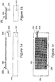
- FIGURE 1 shows parts of apparatus 150 according to a first embodiment of the present invention, and an example portable electrical device (mobile handset) 100 with which the apparatus is used. As originally manufactured the device has no wireless power receiving capability.
- the device 100 has a power-connector 101 which in this case is a socket.
- the apparatus 150 comprises a substantially flat power-receiving element 200, a layer of adhesive 201, a flexible connecting member (flexible wiring) 202 and a power-connector 203 capable of being plugged-in to the device's power-connector 101.
- Figures 1b and 1c show end and plan views of the arrangement of Figure 1a .
- the rear face (underside) of the mobile device 100 is uppermost in Figure 1a , and it is to this face that the element 200 is attached.
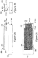
- Figures 2a to 2c shows corresponding views to those of Figures 1a to 1c but for apparatus 160 according to the second embodiment of the present invention.
- the device power connections (first connector means) 111a,b are contact strips instead of a socket.
- These device power connections 111a,b are adapted to connect to corresponding mating strips (second connector means - not shown) of external equipment (not shown) such as a charger.
- a power connector unit 213 of the apparatus has corresponding mating strips (third connector means) 215a,b on an inner face 214 thereof which make electrical contact with the device's power connections 111a,b.
- further connectors (fourth connector means) 217a,b are provided on an outer face 216 of the power connector unit 213 so that other equipment, for example an in-car hands-free unit or charger, having the second connector means may still be connected.
- These further connectors 217a,b are connected electrically to the corresponding contacts 215a,b by a pass-through connection arrangement incorporated into the power connector unit 213.
- the connectors 215a,b and 217a,b may include connectors used for purposes other than power delivery, for example input/output of signals and data.
- FIGS 3a and 3b show plan and side views respectively of one example of a substantially flat power-receiving element 200 for use in embodiments of the present invention.
- a magnetic core consists of six strips of amorphous metal 400 each measuring 50x30x0.02mm, stacked. Around these is wound a coil 300, which could be for example of copper wire, tape, or a stamped or pressed metal. In this case, the coil passes around the core 30 times, with a centre-tap, providing current to three connections 202 which connect to further circuitry described later with reference to Figure 4 .
- the entire element is readily flexible, which is useful in making it conform to any non-flat part of the device to which it is applied, and also makes it less fragile, since the entire element can be less than 0.2mm thick.
- Document EP1221753 discloses a device according to the preamble of claim 1.
- Figure 4 shows circuitry 450 capable of converting the alternating current delivered by the power receiving element into power suitable for use in a portable electronic device.
- a parallel-resonating capacitor 501 tunes the coil, which allows increased power transfer.
- a value of 100's of nF is typical, depending on the exact core materials and coil construction, and therefore inductance.
- the alternating current is full-wave rectified by diodes 500. Schottky diodes with a forward voltage drop of 0.3V provide best performance.
- Capacitor 502 provides smoothing of the DC. The voltage at this point is unregulated, which may be sufficient to send to subsequent electronics within the portable device, if it is capable of taking such.
- Optional voltage regulator 503 limits the voltage for devices which are not capable of taking an unregulated supply. This regulator may be a linear or switch mode type, and may optionally also contain other protection and system management circuitry.
- Optional indicator 504 indicates that power is being received.
- the tuning capacitor may be parallel-resonant or series-resonant.
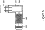
- Figure 5 shows a detail view of one implementation of a power connector 600.
- a barrel-shaped protrusion carries two conducting rings 601 and 602 which mate with contacts within the power input socket of the portable device.
- the circuitry 450 of Figure 4 is contained within the power connector, and the optional power indicator 504 is visible externally.
- the connector 600 is removable from an end 603 of the flexible wiring 202, allowing different power connectors to be fitted to suit the particular device, each with the appropriate circuitry (power electronics) 450.
- one end of the flexible wiring 202 could be removable from the power-receiving element 200 and the other end attached permanently to the power connector 600.
- the removable connections between the flexible wiring and the power connector and/or power-receiving element can be made by any suitable electrical connection arrangement such as a plug and socket.
- the power-receiving element is in the form of a "sticker" 700.
- the element 700 has a layer of adhesive 702 on one surface 701 thereof.
- the element is supplied with a removable backing sheet 703 which protects the adhesive 702 prior to attachment of the element to the portable electrical device.
- the backing sheet 703 is peeled off by a user to expose the layer of adhesive 702 on surface 701. After peeling off the backing sheet 703 the user simply presses the power-receiving element on its adhesive side 702 to the portable electrical device.
- FIG. 7 shows a schematic perspective view of a power-receiving element in another embodiment of the present invention.
- the power-receiving element 800 has, on its side 801 which will be visible to a user when the element is attached to the device, a transparent pocket 802.
- the insert may bear text or pictures, for example a logo or advertising.
- apparatus embodying the present invention is in the form of a replacement cover portion of the portable electrical device itself.
- portable electrical device Commercially available which have replaceable cover portions.
- Handsets for use in mobile communications networks made by several major manufacturers are one example.
- Replacement cover portions for such devices can advantageously carry or incorporate at least the power-receiving element of apparatus embodying the present invention.
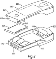
- FIG 8 shows a schematic perspective view of such a handset 900.
- the handset 900 has a battery compartment 902 for holding a removable battery pack 904.
- the removable battery pack 904 is, for example, a rechargeable battery pack.
- the battery pack 904 has terminals (not shown) which connect to corresponding battery connectors 906 of the handset 900 within the battery compartment 902 when the battery pack 904 is installed in the battery compartment.
- the handset 900 also has a power connector 908 at a bottom end 910 thereof.
- a replacement cover portion 950 is adapted to be fitted to the handset 900.
- the replacement cover portion in this embodiment is a rear cover portion and covers the battery compartment 902 of the handset 900 as well as other parts thereof.
- the cover portion 950 has on its inner face or incorporated within it a power-receiving element 952.
- the element 952 may, for example, be the same as the power-receiving element 200 described hereinbefore.
- the cover portion 950 is designed to extend at one end 954 beyond the bottom end 910 of the handset 900. At the end 954 the cover portion 950 has a power connector part 956 carrying one or more power connectors 958.
- the power connector(s) is/are connected in some suitable way (not shown) to the power-receiving element 952, either directly or via power conditioning circuitry such as the circuitry 450 of Figure 4 .
- the power connector(s) 958 is/are adapted to connect to the corresponding power connector(s) of the handset power connector 908.
- This arrangement is convenient in that installation of the cover portion 950 on the handset 900 automatically makes the required electrical connections between the power-receiving element 952 and the power connector 908 of the handset.
- the power connector part 956 of the cover portion 950 may be connected semi-rigidly (e.g. resiliently) instead of rigidly to the remaining parts of the cover portion 950. This can make it easier for the power connector(s) 958 of the cover portion to be connected to the corresponding power connector(s) of the handset 900 when the cover portion is being fitted to the handset.
- FIG 9 shows another embodiment in which the power-receiving element is carried by or incorporated in a replacement cover portion.
- a replacement cover portion 1000 does not have the extended end 954 or the power connector part 956 of the replacement cover portion 950 of Figure 8 .
- an internal power connector part 1002 is connected, preferably via power conditioning circuitry such as the circuitry 450 of Figure 4 , to the power-receiving element 952.
- the connection may be made using flexible wiring 1004.
- the power connector part 1002 is sufficiently thin to enable it to be interposed between the battery terminals of the battery pack 904 and the power connectors 906 formed within the battery compartment 902 of the handset 900.
- the power connector part 1002 has a set of contacts on both its main faces.
- the two sets of contacts are connected together by a pass-through connection arrangement. This enables the power from the battery pack 904 to be supplied to the power connectors 906 when the power-receiving element is not receiving power wirelessly from a transmitter.
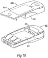
- FIG 10 shows yet another embodiment in which a replacement cover portion 1050 carries or incorporates a rechargeable battery pack 1054 in addition to a power-receiving element 952.
- the electrical connections between the power receiving element 952 and the battery pack 1054 are made by suitable means (not shown) incorporated in or carried by the cover portion 1050.
- the fitting of the replacement cover portion 1050 to the handset 900 brings the battery terminals of the battery pack 1054 into contact with the power connectors 906 of the handset 900.
Landscapes
- Engineering & Computer Science (AREA)
- Theoretical Computer Science (AREA)
- Power Engineering (AREA)
- Computer Networks & Wireless Communication (AREA)
- Physics & Mathematics (AREA)
- General Physics & Mathematics (AREA)
- General Engineering & Computer Science (AREA)
- Signal Processing (AREA)
- Human Computer Interaction (AREA)
- Computer Hardware Design (AREA)
- Charge And Discharge Circuits For Batteries Or The Like (AREA)
- Telephone Set Structure (AREA)
- Power Sources (AREA)
Claims (10)
- Partie de recouvrement de rechange (950) pour un appareil électrique portable (900), la partie de recouvrement (950) portant ou incorporant un élément de réception d'énergie inductive (952) adapté pour recevoir de l'énergie sans fil par induction électromagnétique depuis un émetteur d'énergie lorsque l'élément et l'émetteur sont à proximité l'un de l'autre, et ayant des moyens de connexion (956, 958) à partir desquels une connexion électrique à un connecteur électrique (908) de l'appareil peut être réalisée, pour permettre à l'appareil (900) de recevoir de l'énergie sans fil par induction électromagnétique
dans laquelle
la partie de recouvrement (950) est configurée pour couvrir une partie arrière de l'appareil électrique portable (900),
caractérisé en ce que
la partie de recouvrement (950) est configurée pour s'étendre vers un côté ou une extrémité (954) au-delà d'un côté ou d'une extrémité (910) de l'appareil électrique portable ; et
la partie de recouvrement (950) comporte une partie de connexion d'alimentation (956) portant un ou plusieurs connecteurs d'alimentation (908) connectés de manière opérationnelle à l'élément de réception d'énergie (952) et agencés pour se connecter, lorsque la partie de recouvrement (950) est en place sur l'appareil (900), aux un ou plusieurs connecteurs d'alimentation correspondants (908) de l'appareil électrique portable (900) ; et
ladite partie de connexion d'alimentation (956) est agencée au niveau dudit côté ou de ladite extrémité (954) de la partie de recouvrement (950). - Partie de recouvrement de rechange selon la revendication 1, qui est une partie de recouvrement de rechange pour un combiné d'un réseau de communications mobiles.
- Partie de recouvrement de rechange selon la revendication 1 ou 2, comprenant en outre des circuits de conditionnement d'énergie opérationnels pour conditionner l'énergie reçue par l'élément de réception d'énergie (952) avant délivrance à l'appareil électrique portable (900).
- Partie de recouvrement de rechange selon l'une quelconque des revendications précédentes, dans laquelle la partie de recouvrement forme une peau pour l'appareil électrique portable.
- Partie de recouvrement de rechange selon l'une quelconque des revendications précédentes, dans laquelle ledit élément de réception d'énergie est d'une épaisseur inférieure à 0,2 mm.
- Partie de recouvrement de rechange selon l'une quelconque des revendications précédentes, comprenant des moyens de fixation mécanique adaptés pour fixer la partie de recouvrement de façon mécanique lorsque la partie de recouvrement est utilisée.
- Partie de recouvrement de rechange selon la revendication 6, dans laquelle les moyens de fixation mécanique comprennent une attache, un agencement par encliquetage ou un agencement par coulissement.
- En combinaison, un appareil électrique portable et une partie de recouvrement de rechange selon l'une quelconque des revendications précédentes.
- Procédé pour adapter un appareil électrique portable (900) n'ayant pas de capacité de réception d'énergie inductive pour qu'il ait une telle capacité, le procédé l'étape consistant à :fixer une partie de recouvrement de rechange selon l'une quelconque des revendications précédentes à l'appareil de sorte qu'une connexion électrique audit connecteur d'alimentation (908) de l'appareil soit effectuée à partir des moyens de connexion (956, 958) de la partie de recouvrement de rechange, pour permettre à l'appareil (900) de recevoir de l'énergie sans fil par induction électromagnétique.
- Procédé selon la revendication 9, comprenant le remplacement d'une partie de recouvrement de l'appareil électrique portable, laquelle partie de recouvrement n'a pas de capacité de réception d'énergie inductive, par ladite partie de recouvrement de rechange.
Applications Claiming Priority (2)
| Application Number | Priority Date | Filing Date | Title |
|---|---|---|---|
| GBGB0229141.7A GB0229141D0 (en) | 2002-12-16 | 2002-12-16 | Improvements relating to contact-less power transfer |
| EP03786118.4A EP1573489B1 (fr) | 2002-12-16 | 2003-12-16 | Adaptation de dispositifs électriques portatifs pour la réception sans fil d'énergie |
Related Parent Applications (3)
| Application Number | Title | Priority Date | Filing Date |
|---|---|---|---|
| EP03786118.4 Division | 2003-12-16 | ||
| EP03786118.4A Division-Into EP1573489B1 (fr) | 2002-12-16 | 2003-12-16 | Adaptation de dispositifs électriques portatifs pour la réception sans fil d'énergie |
| EP03786118.4A Division EP1573489B1 (fr) | 2002-12-16 | 2003-12-16 | Adaptation de dispositifs électriques portatifs pour la réception sans fil d'énergie |
Publications (3)
| Publication Number | Publication Date |
|---|---|
| EP2275896A2 EP2275896A2 (fr) | 2011-01-19 |
| EP2275896A3 EP2275896A3 (fr) | 2011-04-06 |
| EP2275896B1 true EP2275896B1 (fr) | 2017-03-22 |
Family
ID=9949665
Family Applications (5)
| Application Number | Title | Priority Date | Filing Date |
|---|---|---|---|
| EP10187342A Withdrawn EP2275895A3 (fr) | 2002-12-16 | 2003-12-16 | Adaptation des dispositifs électriques portables pour recevoir de l'énergie sans fil |
| EP10187345A Ceased EP2275897A3 (fr) | 2002-12-16 | 2003-12-16 | Adaptation des dispositifs électriques portables pour recevoir de l'énergie sans fil |
| EP11152593A Withdrawn EP2330480A1 (fr) | 2002-12-16 | 2003-12-16 | Adaptation des dispositifs électriques portables pour recevoir de l'énergie sans fil |
| EP03786118.4A Expired - Lifetime EP1573489B1 (fr) | 2002-12-16 | 2003-12-16 | Adaptation de dispositifs électriques portatifs pour la réception sans fil d'énergie |
| EP10187343.8A Expired - Lifetime EP2275896B1 (fr) | 2002-12-16 | 2003-12-16 | Adaptation des dispositifs électriques portables pour recevoir de l'énergie sans fil |
Family Applications Before (4)
| Application Number | Title | Priority Date | Filing Date |
|---|---|---|---|
| EP10187342A Withdrawn EP2275895A3 (fr) | 2002-12-16 | 2003-12-16 | Adaptation des dispositifs électriques portables pour recevoir de l'énergie sans fil |
| EP10187345A Ceased EP2275897A3 (fr) | 2002-12-16 | 2003-12-16 | Adaptation des dispositifs électriques portables pour recevoir de l'énergie sans fil |
| EP11152593A Withdrawn EP2330480A1 (fr) | 2002-12-16 | 2003-12-16 | Adaptation des dispositifs électriques portables pour recevoir de l'énergie sans fil |
| EP03786118.4A Expired - Lifetime EP1573489B1 (fr) | 2002-12-16 | 2003-12-16 | Adaptation de dispositifs électriques portatifs pour la réception sans fil d'énergie |
Country Status (7)
| Country | Link |
|---|---|
| US (5) | US8055310B2 (fr) |
| EP (5) | EP2275895A3 (fr) |
| JP (2) | JP4925393B2 (fr) |
| CN (1) | CN100347633C (fr) |
| AU (1) | AU2003295117A1 (fr) |
| GB (1) | GB0229141D0 (fr) |
| WO (1) | WO2004055654A2 (fr) |
Families Citing this family (276)
| Publication number | Priority date | Publication date | Assignee | Title |
|---|---|---|---|---|
| GB2399466B (en) * | 2003-03-10 | 2005-11-16 | Univ City Hong Kong | Battery charging system |
| US8917057B2 (en) | 2002-06-10 | 2014-12-23 | City University Of Hong Kong | Battery charging system |
| EP2685594B1 (fr) | 2002-06-10 | 2017-11-22 | City University of Hong Kong | Chargeur De Batterie Inductif Plat |
| US20120080958A1 (en) * | 2002-12-10 | 2012-04-05 | Pure Energy Solutions, Inc. | Reliable contact and safe system and method for providing power to an electronic device |
| US7982436B2 (en) * | 2002-12-10 | 2011-07-19 | Pure Energy Solutions, Inc. | Battery cover with contact-type power receiver for electrically powered device |
| US7932638B2 (en) * | 2002-12-10 | 2011-04-26 | Pure Energy Solutions, Inc. | Reliable contact and safe system and method for providing power to an electronic device |
| GB0229141D0 (en) * | 2002-12-16 | 2003-01-15 | Splashpower Ltd | Improvements relating to contact-less power transfer |
| US10575376B2 (en) | 2004-02-25 | 2020-02-25 | Lynk Labs, Inc. | AC light emitting diode and AC LED drive methods and apparatus |
| US10499465B2 (en) | 2004-02-25 | 2019-12-03 | Lynk Labs, Inc. | High frequency multi-voltage and multi-brightness LED lighting devices and systems and methods of using same |
| WO2011143510A1 (fr) | 2010-05-12 | 2011-11-17 | Lynk Labs, Inc. | Système d'éclairage à del |
| US8594567B2 (en) | 2004-08-16 | 2013-11-26 | Giesecke & Devrient Gmbh | Controlled wireless charging of an accumulator in a chipcard |
| WO2006018229A1 (fr) | 2004-08-16 | 2006-02-23 | Giesecke & Devrient Gmbh | Operation de chargement sans contact et bidirectionnel entre plusieurs accumulateurs |
| US7970870B2 (en) | 2005-06-24 | 2011-06-28 | Microsoft Corporation | Extending digital artifacts through an interactive surface |
| CN102983639B (zh) * | 2005-07-12 | 2016-01-27 | 麻省理工学院 | 无线非辐射能量传递 |
| US7825543B2 (en) * | 2005-07-12 | 2010-11-02 | Massachusetts Institute Of Technology | Wireless energy transfer |
| US7514899B2 (en) | 2005-11-18 | 2009-04-07 | Avago Technologies Ecbu Ip (Singapore) Pte. Ltd. | Method and apparatus for optical wireless charging |
| GB0524790D0 (en) * | 2005-12-05 | 2006-01-11 | Univ City Hong Kong | Apparatus and method for the charging of electrical devices |
| FR2895164A1 (fr) * | 2005-12-19 | 2007-06-22 | France Telecom | Enveloppe et etui permettant la recharge d'un appareil electronique en situation de mobilite |
| US9130602B2 (en) | 2006-01-18 | 2015-09-08 | Qualcomm Incorporated | Method and apparatus for delivering energy to an electrical or electronic device via a wireless link |
| US8447234B2 (en) | 2006-01-18 | 2013-05-21 | Qualcomm Incorporated | Method and system for powering an electronic device via a wireless link |
| US8169185B2 (en) | 2006-01-31 | 2012-05-01 | Mojo Mobility, Inc. | System and method for inductive charging of portable devices |
| US7952322B2 (en) | 2006-01-31 | 2011-05-31 | Mojo Mobility, Inc. | Inductive power source and charging system |
| US11201500B2 (en) | 2006-01-31 | 2021-12-14 | Mojo Mobility, Inc. | Efficiencies and flexibilities in inductive (wireless) charging |
| JP4635918B2 (ja) * | 2006-03-13 | 2011-02-23 | ソニー株式会社 | 携帯電話機の保護カバーおよび携帯電話機の充電システム。 |
| WO2007108819A1 (fr) * | 2006-03-22 | 2007-09-27 | Powercast Corporation | Method and apparatus for implementation of a wireless power supply |
| US11329511B2 (en) | 2006-06-01 | 2022-05-10 | Mojo Mobility Inc. | Power source, charging system, and inductive receiver for mobile devices |
| US7948208B2 (en) | 2006-06-01 | 2011-05-24 | Mojo Mobility, Inc. | Power source, charging system, and inductive receiver for mobile devices |
| JP4855150B2 (ja) * | 2006-06-09 | 2012-01-18 | 株式会社トプコン | 眼底観察装置、眼科画像処理装置及び眼科画像処理プログラム |
| US9129741B2 (en) | 2006-09-14 | 2015-09-08 | Qualcomm Incorporated | Method and apparatus for wireless power transmission |
| US7706771B2 (en) * | 2007-02-08 | 2010-04-27 | Broadcom Corporation | Inductive powering for a mobile communication device and method for use therewith |
| US9774086B2 (en) | 2007-03-02 | 2017-09-26 | Qualcomm Incorporated | Wireless power apparatus and methods |
| US8199117B2 (en) | 2007-05-09 | 2012-06-12 | Microsoft Corporation | Archive for physical and digital objects |
| US9421388B2 (en) | 2007-06-01 | 2016-08-23 | Witricity Corporation | Power generation for implantable devices |
| US8115448B2 (en) | 2007-06-01 | 2012-02-14 | Michael Sasha John | Systems and methods for wireless power |
| US9124120B2 (en) | 2007-06-11 | 2015-09-01 | Qualcomm Incorporated | Wireless power system and proximity effects |
| TW200901599A (en) * | 2007-06-29 | 2009-01-01 | rong-cong Lin | Battery cover |
| CN101842962B (zh) | 2007-08-09 | 2014-10-08 | 高通股份有限公司 | 增加谐振器的q因数 |
| EP2188867A4 (fr) * | 2007-09-13 | 2014-12-10 | Qualcomm Inc | Antenne pour applications d'électricité sans fil |
| CN101803109A (zh) | 2007-09-13 | 2010-08-11 | 高通股份有限公司 | 最大化来自无线功率磁谐振器的功率产量 |
| EP2201641A1 (fr) | 2007-09-17 | 2010-06-30 | Qualcomm Incorporated | Emetteurs et récepteurs pour un transfert d'énergie sans fil |
| FI120853B (fi) | 2007-09-18 | 2010-03-31 | Powerkiss Oy | Energiansiirtojärjestely ja -menetelmä |
| US11297705B2 (en) | 2007-10-06 | 2022-04-05 | Lynk Labs, Inc. | Multi-voltage and multi-brightness LED lighting devices and methods of using same |
| US11317495B2 (en) | 2007-10-06 | 2022-04-26 | Lynk Labs, Inc. | LED circuits and assemblies |
| KR101606664B1 (ko) | 2007-10-11 | 2016-03-25 | 퀄컴 인코포레이티드 | 자기 기계 시스템을 이용하는 무선 전력 전송 |
| ATE523835T1 (de) * | 2007-10-17 | 2011-09-15 | Access Business Group Int Llc | Drahtlose stromversorgungssysteme für laptops und tragbare elektronische geräte |
| US7986059B2 (en) * | 2008-01-04 | 2011-07-26 | Pure Energy Solutions, Inc. | Device cover with embedded power receiver |
| US8127155B2 (en) | 2008-01-07 | 2012-02-28 | Access Business Group International Llc | Wireless power adapter for computer |
| US8367235B2 (en) * | 2008-01-18 | 2013-02-05 | Mophie, Inc. | Battery pack, holster, and extendible processing and interface platform for mobile devices |
| DE102008007822A1 (de) * | 2008-02-07 | 2009-08-13 | Fraunhofer-Gesellschaft zur Förderung der angewandten Forschung e.V. | Drahtlose Ladeschnittstelle für einen Energiespeicher |
| WO2009142795A1 (fr) * | 2008-03-03 | 2009-11-26 | Mitch Randall | Appareil et procédé permettant d'équiper ultérieurement une large gamme de dispositifs mobiles pour la réception sans fil d'énergie |
| US20100022285A1 (en) * | 2008-03-03 | 2010-01-28 | Wildcharge, Inc. | Apparatus and method for retrofitting a broad range of mobile devices to receive wireless power |
| US8629576B2 (en) | 2008-03-28 | 2014-01-14 | Qualcomm Incorporated | Tuning and gain control in electro-magnetic power systems |
| US20110050164A1 (en) | 2008-05-07 | 2011-03-03 | Afshin Partovi | System and methods for inductive charging, and improvements and uses thereof |
| US9178387B2 (en) | 2008-05-13 | 2015-11-03 | Qualcomm Incorporated | Receive antenna for wireless power transfer |
| US8878393B2 (en) | 2008-05-13 | 2014-11-04 | Qualcomm Incorporated | Wireless power transfer for vehicles |
| JP2011523844A (ja) | 2008-05-14 | 2011-08-18 | マサチューセッツ インスティテュート オブ テクノロジー | 干渉増大を含む無線エネルギー伝達装置及び方法 |
| US7855529B2 (en) | 2008-07-16 | 2010-12-21 | ConvenientPower HK Ltd. | Inductively powered sleeve for mobile electronic device |
| US8946938B2 (en) | 2008-09-27 | 2015-02-03 | Witricity Corporation | Safety systems for wireless energy transfer in vehicle applications |
| US8629578B2 (en) | 2008-09-27 | 2014-01-14 | Witricity Corporation | Wireless energy transfer systems |
| US8487480B1 (en) | 2008-09-27 | 2013-07-16 | Witricity Corporation | Wireless energy transfer resonator kit |
| US9396867B2 (en) | 2008-09-27 | 2016-07-19 | Witricity Corporation | Integrated resonator-shield structures |
| US8937408B2 (en) | 2008-09-27 | 2015-01-20 | Witricity Corporation | Wireless energy transfer for medical applications |
| US8304935B2 (en) | 2008-09-27 | 2012-11-06 | Witricity Corporation | Wireless energy transfer using field shaping to reduce loss |
| US8471410B2 (en) | 2008-09-27 | 2013-06-25 | Witricity Corporation | Wireless energy transfer over distance using field shaping to improve the coupling factor |
| US8912687B2 (en) | 2008-09-27 | 2014-12-16 | Witricity Corporation | Secure wireless energy transfer for vehicle applications |
| US8441154B2 (en) | 2008-09-27 | 2013-05-14 | Witricity Corporation | Multi-resonator wireless energy transfer for exterior lighting |
| US9093853B2 (en) | 2008-09-27 | 2015-07-28 | Witricity Corporation | Flexible resonator attachment |
| US8400017B2 (en) | 2008-09-27 | 2013-03-19 | Witricity Corporation | Wireless energy transfer for computer peripheral applications |
| US8466583B2 (en) | 2008-09-27 | 2013-06-18 | Witricity Corporation | Tunable wireless energy transfer for outdoor lighting applications |
| US8598743B2 (en) | 2008-09-27 | 2013-12-03 | Witricity Corporation | Resonator arrays for wireless energy transfer |
| US9065423B2 (en) | 2008-09-27 | 2015-06-23 | Witricity Corporation | Wireless energy distribution system |
| JP2012504387A (ja) | 2008-09-27 | 2012-02-16 | ウィトリシティ コーポレーション | 無線エネルギー伝達システム |
| US8957549B2 (en) | 2008-09-27 | 2015-02-17 | Witricity Corporation | Tunable wireless energy transfer for in-vehicle applications |
| US8933594B2 (en) | 2008-09-27 | 2015-01-13 | Witricity Corporation | Wireless energy transfer for vehicles |
| US8587153B2 (en) | 2008-09-27 | 2013-11-19 | Witricity Corporation | Wireless energy transfer using high Q resonators for lighting applications |
| US8772973B2 (en) | 2008-09-27 | 2014-07-08 | Witricity Corporation | Integrated resonator-shield structures |
| US8461721B2 (en) | 2008-09-27 | 2013-06-11 | Witricity Corporation | Wireless energy transfer using object positioning for low loss |
| US9601261B2 (en) | 2008-09-27 | 2017-03-21 | Witricity Corporation | Wireless energy transfer using repeater resonators |
| US8569914B2 (en) | 2008-09-27 | 2013-10-29 | Witricity Corporation | Wireless energy transfer using object positioning for improved k |
| US9318922B2 (en) | 2008-09-27 | 2016-04-19 | Witricity Corporation | Mechanically removable wireless power vehicle seat assembly |
| US8461720B2 (en) | 2008-09-27 | 2013-06-11 | Witricity Corporation | Wireless energy transfer using conducting surfaces to shape fields and reduce loss |
| US9246336B2 (en) | 2008-09-27 | 2016-01-26 | Witricity Corporation | Resonator optimizations for wireless energy transfer |
| US8482158B2 (en) | 2008-09-27 | 2013-07-09 | Witricity Corporation | Wireless energy transfer using variable size resonators and system monitoring |
| US9744858B2 (en) | 2008-09-27 | 2017-08-29 | Witricity Corporation | System for wireless energy distribution in a vehicle |
| US8410636B2 (en) | 2008-09-27 | 2013-04-02 | Witricity Corporation | Low AC resistance conductor designs |
| US8928276B2 (en) | 2008-09-27 | 2015-01-06 | Witricity Corporation | Integrated repeaters for cell phone applications |
| US8947186B2 (en) | 2008-09-27 | 2015-02-03 | Witricity Corporation | Wireless energy transfer resonator thermal management |
| US8963488B2 (en) | 2008-09-27 | 2015-02-24 | Witricity Corporation | Position insensitive wireless charging |
| US8476788B2 (en) | 2008-09-27 | 2013-07-02 | Witricity Corporation | Wireless energy transfer with high-Q resonators using field shaping to improve K |
| US9601266B2 (en) | 2008-09-27 | 2017-03-21 | Witricity Corporation | Multiple connected resonators with a single electronic circuit |
| US9577436B2 (en) | 2008-09-27 | 2017-02-21 | Witricity Corporation | Wireless energy transfer for implantable devices |
| US9160203B2 (en) | 2008-09-27 | 2015-10-13 | Witricity Corporation | Wireless powered television |
| US8669676B2 (en) | 2008-09-27 | 2014-03-11 | Witricity Corporation | Wireless energy transfer across variable distances using field shaping with magnetic materials to improve the coupling factor |
| US8643326B2 (en) | 2008-09-27 | 2014-02-04 | Witricity Corporation | Tunable wireless energy transfer systems |
| US8461722B2 (en) | 2008-09-27 | 2013-06-11 | Witricity Corporation | Wireless energy transfer using conducting surfaces to shape field and improve K |
| US8552592B2 (en) | 2008-09-27 | 2013-10-08 | Witricity Corporation | Wireless energy transfer with feedback control for lighting applications |
| US8901778B2 (en) | 2008-09-27 | 2014-12-02 | Witricity Corporation | Wireless energy transfer with variable size resonators for implanted medical devices |
| US8497601B2 (en) | 2008-09-27 | 2013-07-30 | Witricity Corporation | Wireless energy transfer converters |
| US8723366B2 (en) | 2008-09-27 | 2014-05-13 | Witricity Corporation | Wireless energy transfer resonator enclosures |
| US8587155B2 (en) | 2008-09-27 | 2013-11-19 | Witricity Corporation | Wireless energy transfer using repeater resonators |
| US8692410B2 (en) | 2008-09-27 | 2014-04-08 | Witricity Corporation | Wireless energy transfer with frequency hopping |
| US9544683B2 (en) | 2008-09-27 | 2017-01-10 | Witricity Corporation | Wirelessly powered audio devices |
| US9035499B2 (en) | 2008-09-27 | 2015-05-19 | Witricity Corporation | Wireless energy transfer for photovoltaic panels |
| US8324759B2 (en) | 2008-09-27 | 2012-12-04 | Witricity Corporation | Wireless energy transfer using magnetic materials to shape field and reduce loss |
| US8922066B2 (en) | 2008-09-27 | 2014-12-30 | Witricity Corporation | Wireless energy transfer with multi resonator arrays for vehicle applications |
| US9184595B2 (en) | 2008-09-27 | 2015-11-10 | Witricity Corporation | Wireless energy transfer in lossy environments |
| US8901779B2 (en) | 2008-09-27 | 2014-12-02 | Witricity Corporation | Wireless energy transfer with resonator arrays for medical applications |
| US9106203B2 (en) | 2008-09-27 | 2015-08-11 | Witricity Corporation | Secure wireless energy transfer in medical applications |
| US8692412B2 (en) | 2008-09-27 | 2014-04-08 | Witricity Corporation | Temperature compensation in a wireless transfer system |
| US9601270B2 (en) | 2008-09-27 | 2017-03-21 | Witricity Corporation | Low AC resistance conductor designs |
| US9515494B2 (en) | 2008-09-27 | 2016-12-06 | Witricity Corporation | Wireless power system including impedance matching network |
| US8686598B2 (en) | 2008-09-27 | 2014-04-01 | Witricity Corporation | Wireless energy transfer for supplying power and heat to a device |
| US8907531B2 (en) | 2008-09-27 | 2014-12-09 | Witricity Corporation | Wireless energy transfer with variable size resonators for medical applications |
| US9105959B2 (en) | 2008-09-27 | 2015-08-11 | Witricity Corporation | Resonator enclosure |
| US8362651B2 (en) | 2008-10-01 | 2013-01-29 | Massachusetts Institute Of Technology | Efficient near-field wireless energy transfer using adiabatic system variations |
| US8810194B2 (en) * | 2008-11-20 | 2014-08-19 | Qualcomm Incorporated | Retrofitting wireless power and near-field communication in electronic devices |
| JP5141518B2 (ja) * | 2008-11-28 | 2013-02-13 | 富士通株式会社 | 携帯端末装置 |
| EP2377296B1 (fr) * | 2009-01-05 | 2019-10-16 | QUALCOMM Incorporated | Schéma de connecteur intérieur en accessoire de dispositif informatique mobile avec segment de logement amovible |
| KR20140117690A (ko) * | 2009-02-05 | 2014-10-07 | 퀄컴 인코포레이티드 | 전자 디바이스의 무선 전력공급 및 근거리장 통신 개장 |
| US8854224B2 (en) | 2009-02-10 | 2014-10-07 | Qualcomm Incorporated | Conveying device information relating to wireless charging |
| US9312924B2 (en) | 2009-02-10 | 2016-04-12 | Qualcomm Incorporated | Systems and methods relating to multi-dimensional wireless charging |
| US20100201312A1 (en) | 2009-02-10 | 2010-08-12 | Qualcomm Incorporated | Wireless power transfer for portable enclosures |
| KR101083630B1 (ko) * | 2009-05-22 | 2011-11-17 | 정춘길 | 무접점 방식의 배터리 충전을 위한 제어모듈 배치 구조 |
| US9312728B2 (en) * | 2009-08-24 | 2016-04-12 | Access Business Group International Llc | Physical and virtual identification in a wireless power network |
| US20110210617A1 (en) * | 2009-08-28 | 2011-09-01 | Pure Energy Solutions, Inc. | Power transmission across a substantially planar interface by magnetic induction and geometrically-complimentary magnetic field structures |
| US12279345B2 (en) | 2009-12-28 | 2025-04-15 | Lynk Labs, Inc. | Light emitting diode and LED drive apparatus |
| JP6144620B2 (ja) | 2010-04-08 | 2017-06-07 | アクセス ビジネス グループ インターナショナル リミテッド ライアビリティ カンパニー | POS(pointofsale)誘導性システムと方法 |
| TWI431887B (zh) | 2010-05-21 | 2014-03-21 | 宏達國際電子股份有限公司 | 與一電池相結合之無線充電封套及其相關無線充電系統 |
| CN102263425B (zh) * | 2010-05-28 | 2014-08-27 | 宏达国际电子股份有限公司 | 与电池相结合的无线充电封套及其相关无线充电系统 |
| WO2011156768A2 (fr) | 2010-06-11 | 2011-12-15 | Mojo Mobility, Inc. | Système de transfert d'énergie sans fil prenant en charge l'interopérabilité et aimants multipolaires à utiliser avec ce système |
| US20120106103A1 (en) * | 2010-06-23 | 2012-05-03 | Tanios Nohra | Radio frequency energy harvesting enclosure for radio frequency connected devices |
| KR101441453B1 (ko) * | 2010-08-25 | 2014-09-18 | 한국전자통신연구원 | 무선 에너지 전송을 위한 자기 공진체에서 전기장 및 복사전력 감소 장치 및 그 방법 |
| US9602168B2 (en) | 2010-08-31 | 2017-03-21 | Witricity Corporation | Communication in wireless energy transfer systems |
| US8759721B1 (en) * | 2010-11-02 | 2014-06-24 | Piatto Technologies, Inc. | Heated or cooled dishwasher safe dishware and drinkware |
| US9814331B2 (en) | 2010-11-02 | 2017-11-14 | Ember Technologies, Inc. | Heated or cooled dishware and drinkware |
| US11950726B2 (en) * | 2010-11-02 | 2024-04-09 | Ember Technologies, Inc. | Drinkware container with active temperature control |
| CN105496128B (zh) * | 2010-11-02 | 2020-06-09 | 恩伯技术公司 | 马克杯系统 |
| US10010213B2 (en) | 2010-11-02 | 2018-07-03 | Ember Technologies, Inc. | Heated or cooled dishware and drinkware and food containers |
| US9035222B2 (en) * | 2010-11-02 | 2015-05-19 | Oromo Technologies, Inc. | Heated or cooled dishware and drinkware |
| CN102480149A (zh) * | 2010-11-29 | 2012-05-30 | 和硕联合科技股份有限公司 | 多功能背夹装置 |
| US9178369B2 (en) | 2011-01-18 | 2015-11-03 | Mojo Mobility, Inc. | Systems and methods for providing positioning freedom, and support of different voltages, protocols, and power levels in a wireless power system |
| US11342777B2 (en) | 2011-01-18 | 2022-05-24 | Mojo Mobility, Inc. | Powering and/or charging with more than one protocol |
| US9496732B2 (en) | 2011-01-18 | 2016-11-15 | Mojo Mobility, Inc. | Systems and methods for wireless power transfer |
| US10115520B2 (en) | 2011-01-18 | 2018-10-30 | Mojo Mobility, Inc. | Systems and method for wireless power transfer |
| US20130293191A1 (en) | 2011-01-26 | 2013-11-07 | Panasonic Corporation | Non-contact charging module and non-contact charging instrument |
| CN103384879A (zh) * | 2011-02-03 | 2013-11-06 | 泰格斯集团国际公司 | 便携式电子装置插接站 |
| CN102130482A (zh) * | 2011-03-21 | 2011-07-20 | 深圳桑菲消费通信有限公司 | 一种通用多功能无线充电套 |
| US20120244969A1 (en) | 2011-03-25 | 2012-09-27 | May Patents Ltd. | System and Method for a Motion Sensing Device |
| EP2712053A4 (fr) * | 2011-06-14 | 2014-11-05 | Panasonic Corp | Appareil de communication |
| GB2492323B (en) * | 2011-06-22 | 2014-03-12 | Sandal Plc | Portable charging apparatus |
| US8660495B2 (en) * | 2011-07-05 | 2014-02-25 | Hewlett-Packard Development Company, L.P. | Accessory display system |
| US9948145B2 (en) | 2011-07-08 | 2018-04-17 | Witricity Corporation | Wireless power transfer for a seat-vest-helmet system |
| CN108110907B (zh) | 2011-08-04 | 2022-08-02 | 韦特里西提公司 | 可调谐无线电源架构 |
| US20140239809A1 (en) | 2011-08-18 | 2014-08-28 | Lynk Labs, Inc. | Devices and systems having ac led circuits and methods of driving the same |
| US8909149B2 (en) * | 2011-08-26 | 2014-12-09 | Hewlett-Packard Development Company, L.P. | Media module of a device |
| WO2013031025A1 (fr) | 2011-09-02 | 2013-03-07 | 富士通株式会社 | Relais de puissance |
| KR102010943B1 (ko) | 2011-09-09 | 2019-08-14 | 위트리시티 코포레이션 | 무선 에너지 전송 시스템에서의 이물질 검출 |
| US20130062966A1 (en) | 2011-09-12 | 2013-03-14 | Witricity Corporation | Reconfigurable control architectures and algorithms for electric vehicle wireless energy transfer systems |
| KR101979266B1 (ko) * | 2011-09-30 | 2019-08-28 | 삼성전자주식회사 | 무선 충전 모듈을 구비하는 휴대용 단말기 |
| US9948126B2 (en) | 2011-09-30 | 2018-04-17 | Samsung Electronics Co., Ltd. | Portable terminal having wireless charging module |
| US9318257B2 (en) | 2011-10-18 | 2016-04-19 | Witricity Corporation | Wireless energy transfer for packaging |
| WO2013065245A1 (fr) | 2011-11-02 | 2013-05-10 | パナソニック株式会社 | Bobine pour communication sans fil sans contact, bobine de transmission, terminal sans fil mobile |
| US10204734B2 (en) | 2011-11-02 | 2019-02-12 | Panasonic Corporation | Electronic device including non-contact charging module and near field communication antenna |
| HK1200602A1 (en) | 2011-11-04 | 2015-08-07 | WiTricity公司 | Wireless energy transfer modeling tool |
| WO2013082609A1 (fr) | 2011-12-02 | 2013-06-06 | Lynk Labs, Inc. | Dispositifs d'éclairage par del à faible distorsion harmonique totale (dht) à commande de température de couleur et leurs systèmes et procédés de pilotage |
| EP2793173A4 (fr) * | 2011-12-14 | 2015-08-05 | Appareil terminal mobile et procédé permettant de régler la fréquence de résonance d'une antenne rfid de cet appareil | |
| TW201330442A (zh) * | 2012-01-02 | 2013-07-16 | 致伸科技股份有限公司 | 無線充電傳輸裝置 |
| KR20130081620A (ko) | 2012-01-09 | 2013-07-17 | 주식회사 케이더파워 | 무선 충전 시스템용 수신기 |
| EP2807720A4 (fr) | 2012-01-26 | 2015-12-02 | Witricity Corp | Transfert d'énergie sans fil à champs réduits |
| JP2013169122A (ja) | 2012-02-17 | 2013-08-29 | Panasonic Corp | 非接触充電モジュール及びそれを備えた携帯端末 |
| US9722447B2 (en) | 2012-03-21 | 2017-08-01 | Mojo Mobility, Inc. | System and method for charging or powering devices, such as robots, electric vehicles, or other mobile devices or equipment |
| US20130271069A1 (en) | 2012-03-21 | 2013-10-17 | Mojo Mobility, Inc. | Systems and methods for wireless power transfer |
| US8774716B2 (en) * | 2012-03-29 | 2014-07-08 | Auden Techno Corp. | Mobile terminal extension case |
| US8684012B1 (en) * | 2012-05-31 | 2014-04-01 | Denise Lynn Ryan | Remote control rollers |
| US9343922B2 (en) | 2012-06-27 | 2016-05-17 | Witricity Corporation | Wireless energy transfer for rechargeable batteries |
| JP6008237B2 (ja) | 2012-06-28 | 2016-10-19 | パナソニックIpマネジメント株式会社 | 携帯端末 |
| JP6112383B2 (ja) | 2012-06-28 | 2017-04-12 | パナソニックIpマネジメント株式会社 | 携帯端末 |
| US9287607B2 (en) | 2012-07-31 | 2016-03-15 | Witricity Corporation | Resonator fine tuning |
| US9179558B1 (en) | 2012-09-17 | 2015-11-03 | Brite Case, LLC | Case with panel for display |
| US9595378B2 (en) | 2012-09-19 | 2017-03-14 | Witricity Corporation | Resonator enclosure |
| CN103022404B (zh) * | 2012-09-27 | 2015-05-27 | 珠海德百祺科技有限公司 | 移动终端和用于该移动终端的电池 |
| US20140091756A1 (en) * | 2012-10-02 | 2014-04-03 | Witricity Corporation | Wireless power transfer |
| KR20150038280A (ko) | 2012-10-17 | 2015-04-08 | 가부시키가이샤 무라타 세이사쿠쇼 | 와이어리스 수전 장치, 와이어리스 송전 장치, 및 와이어리스 송수전 장치 |
| US9465064B2 (en) | 2012-10-19 | 2016-10-11 | Witricity Corporation | Foreign object detection in wireless energy transfer systems |
| US11843260B2 (en) | 2012-11-09 | 2023-12-12 | California Institute Of Technology | Generator unit for wireless power transfer |
| US11616520B2 (en) | 2012-11-09 | 2023-03-28 | California Institute Of Technology | RF receiver |
| US10367380B2 (en) * | 2012-11-09 | 2019-07-30 | California Institute Of Technology | Smart RF lensing: efficient, dynamic and mobile wireless power transfer |
| US9449757B2 (en) | 2012-11-16 | 2016-09-20 | Witricity Corporation | Systems and methods for wireless power system with improved performance and/or ease of use |
| CN105052117A (zh) * | 2013-03-19 | 2015-11-11 | 惠普发展公司,有限责任合伙企业 | 互连组件 |
| US9837846B2 (en) | 2013-04-12 | 2017-12-05 | Mojo Mobility, Inc. | System and method for powering or charging receivers or devices having small surface areas or volumes |
| US9601267B2 (en) | 2013-07-03 | 2017-03-21 | Qualcomm Incorporated | Wireless power transmitter with a plurality of magnetic oscillators |
| US9716524B2 (en) * | 2013-08-08 | 2017-07-25 | Ramin Rostami | System, apparatus and method for generic electronic device power module and case formation |
| JP2016534698A (ja) | 2013-08-14 | 2016-11-04 | ワイトリシティ コーポレーションWitricity Corporation | インピーダンス同調 |
| TWM469671U (zh) * | 2013-08-22 | 2014-01-01 | Kuo-Zhi Huang | 可被無線供電的電子裝置及其無線電力結構 |
| TWI509937B (zh) | 2013-09-16 | 2015-11-21 | 萬國商業機器公司 | 用於一第一裝置對一第二裝置進行無線充電的方法,充電裝置,及充電系統 |
| KR102473074B1 (ko) | 2013-11-22 | 2022-11-30 | 캘리포니아 인스티튜트 오브 테크놀로지 | 무선 전력 송신을 위한 생성기 유닛 |
| US9780573B2 (en) | 2014-02-03 | 2017-10-03 | Witricity Corporation | Wirelessly charged battery system |
| WO2015123614A2 (fr) | 2014-02-14 | 2015-08-20 | Witricity Corporation | Détection d'objet pour des systèmes de transfert d'énergie sans fil |
| KR101762778B1 (ko) | 2014-03-04 | 2017-07-28 | 엘지이노텍 주식회사 | 무선 충전 및 통신 기판 그리고 무선 충전 및 통신 장치 |
| US10664772B1 (en) | 2014-03-07 | 2020-05-26 | Steelcase Inc. | Method and system for facilitating collaboration sessions |
| US9716861B1 (en) | 2014-03-07 | 2017-07-25 | Steelcase Inc. | Method and system for facilitating collaboration sessions |
| US20150270737A1 (en) * | 2014-03-21 | 2015-09-24 | Sony Corporation | Terminal device cover and a terminal device for contactless charging |
| US9892849B2 (en) | 2014-04-17 | 2018-02-13 | Witricity Corporation | Wireless power transfer systems with shield openings |
| US9842687B2 (en) | 2014-04-17 | 2017-12-12 | Witricity Corporation | Wireless power transfer systems with shaped magnetic components |
| US9837860B2 (en) | 2014-05-05 | 2017-12-05 | Witricity Corporation | Wireless power transmission systems for elevators |
| CN106489082B (zh) | 2014-05-07 | 2021-09-21 | 无线电力公司 | 无线能量传送系统中的异物检测 |
| US9955318B1 (en) | 2014-06-05 | 2018-04-24 | Steelcase Inc. | Space guidance and management system and method |
| US9766079B1 (en) | 2014-10-03 | 2017-09-19 | Steelcase Inc. | Method and system for locating resources and communicating within an enterprise |
| US9380682B2 (en) | 2014-06-05 | 2016-06-28 | Steelcase Inc. | Environment optimization for space based on presence and activities |
| US10614694B1 (en) | 2014-06-06 | 2020-04-07 | Steelcase Inc. | Powered furniture assembly |
| US11744376B2 (en) | 2014-06-06 | 2023-09-05 | Steelcase Inc. | Microclimate control systems and methods |
| US10433646B1 (en) | 2014-06-06 | 2019-10-08 | Steelcaase Inc. | Microclimate control systems and methods |
| US9954375B2 (en) | 2014-06-20 | 2018-04-24 | Witricity Corporation | Wireless power transfer systems for surfaces |
| WO2015196302A1 (fr) | 2014-06-26 | 2015-12-30 | Solace Power Inc. | Système de transmission de puissance de champ électrique sans fil, émetteur et récepteur pour ce dernier et procédé de transfert sans fil de puissance |
| US10574091B2 (en) | 2014-07-08 | 2020-02-25 | Witricity Corporation | Enclosures for high power wireless power transfer systems |
| US9842688B2 (en) | 2014-07-08 | 2017-12-12 | Witricity Corporation | Resonator balancing in wireless power transfer systems |
| CN111193330A (zh) | 2014-08-19 | 2020-05-22 | 加州理工学院 | 用于无线功率传输的恢复单元和从rf波生成dc功率的方法 |
| WO2016033697A1 (fr) | 2014-09-05 | 2016-03-10 | Solace Power Inc. | Système de transfert de puissance de champ électrique sans fil, procédé, émetteur et récepteur associés |
| US9852388B1 (en) | 2014-10-03 | 2017-12-26 | Steelcase, Inc. | Method and system for locating resources and communicating within an enterprise |
| US9904323B2 (en) | 2014-10-28 | 2018-02-27 | Targus International Llc | Power and data adapter, and related systems and methods |
| KR101628019B1 (ko) * | 2014-12-10 | 2016-06-13 | 오지훈 | 무선 충전 수신 모듈 |
| WO2016100288A1 (fr) | 2014-12-15 | 2016-06-23 | Targus International Llc | Adaptateur d'alimentation électrique et de données |
| US9843217B2 (en) | 2015-01-05 | 2017-12-12 | Witricity Corporation | Wireless energy transfer for wearables |
| US9782036B2 (en) | 2015-02-24 | 2017-10-10 | Ember Technologies, Inc. | Heated or cooled portable drinkware |
| USD861653S1 (en) | 2015-05-27 | 2019-10-01 | Mophie Inc. | Protective battery case for mobile communications device |
| US10733371B1 (en) | 2015-06-02 | 2020-08-04 | Steelcase Inc. | Template based content preparation system for use with a plurality of space types |
| US10027150B2 (en) * | 2015-06-18 | 2018-07-17 | Serene Devices Llc | RFI/EMI shielding enclosure containing wireless charging element for personal electronic devices security |
| WO2017062647A1 (fr) | 2015-10-06 | 2017-04-13 | Witricity Corporation | Détection d'étiquette d'identification par radiofréquence (rfid) et de transpondeur dans des systèmes de transfert d'énergie sans fil |
| JP2018538517A (ja) | 2015-10-14 | 2018-12-27 | ワイトリシティ コーポレーションWitricity Corporation | 無線エネルギー伝送システムにおける位相及び振幅の検出 |
| WO2017070227A1 (fr) | 2015-10-19 | 2017-04-27 | Witricity Corporation | Détection d'objet étranger dans des systèmes de transfert d'énergie sans fil |
| CN108781002B (zh) | 2015-10-22 | 2021-07-06 | 韦特里西提公司 | 无线能量传输系统中的动态调谐 |
| US12353703B2 (en) | 2015-10-28 | 2025-07-08 | Microsoft Technology Licensing, Llc. | Computing device having user-input accessory |
| US10075019B2 (en) | 2015-11-20 | 2018-09-11 | Witricity Corporation | Voltage source isolation in wireless power transfer systems |
| CN109075613B (zh) | 2016-02-02 | 2022-05-31 | 韦特里西提公司 | 控制无线电力传输系统 |
| WO2017139406A1 (fr) | 2016-02-08 | 2017-08-17 | Witricity Corporation | Commande de condensateur pwm |
| US10033203B1 (en) | 2016-02-10 | 2018-07-24 | James Frederick Snyder, Jr. | Apparatus and method for charging at least one portable electrical device |
| DE102017002146A1 (de) | 2016-03-04 | 2017-09-07 | Logitech Europe S.A. | Drahtloses Laden für eine Eingabeeinrichtung |
| US10622824B2 (en) * | 2016-03-04 | 2020-04-14 | Logitech Europe S.A. | Wireless charging for an input device |
| WO2017192396A1 (fr) | 2016-05-02 | 2017-11-09 | Ember Technologies, Inc. | Nécessaire à boire chauffé ou refroidi |
| JP6522153B2 (ja) | 2016-05-12 | 2019-05-29 | エンバー テクノロジーズ, インコーポレイテッド | 飲料用容器及び食器並びに飲料用容器及び食器のためのアクティブ制御モジュール |
| US9921726B1 (en) | 2016-06-03 | 2018-03-20 | Steelcase Inc. | Smart workstation method and system |
| US10705566B2 (en) | 2016-09-09 | 2020-07-07 | Targus International Llc | Systems, methods and devices for native and virtualized video in a hybrid docking station |
| KR20180035662A (ko) | 2016-09-29 | 2018-04-06 | 엠버 테크놀로지스 인코포레이티드 | 가열되거나 냉각된 음료용기 |
| US9995529B1 (en) * | 2016-12-08 | 2018-06-12 | Nova Laboratories | Temperature-regulating containment system |
| US10264213B1 (en) | 2016-12-15 | 2019-04-16 | Steelcase Inc. | Content amplification system and method |
| WO2018218252A1 (fr) | 2017-05-26 | 2018-11-29 | California Institute Of Technology | Procédé et appareil de focalisation et de suivi dynamique de lentille rf d'unité de récupération d'énergie sans fil |
| US10283952B2 (en) | 2017-06-22 | 2019-05-07 | Bretford Manufacturing, Inc. | Rapidly deployable floor power system |
| EP3646434B1 (fr) | 2017-06-29 | 2025-01-22 | Witricity Corporation | Protection et commande de systèmes d'alimentation sans fil |
| US10663498B2 (en) | 2017-07-20 | 2020-05-26 | Targus International Llc | Systems, methods and devices for remote power management and discovery |
| US11231448B2 (en) | 2017-07-20 | 2022-01-25 | Targus International Llc | Systems, methods and devices for remote power management and discovery |
| US11079077B2 (en) | 2017-08-31 | 2021-08-03 | Lynk Labs, Inc. | LED lighting system and installation methods |
| US20190110643A1 (en) * | 2017-10-14 | 2019-04-18 | Gloria Contreras | Smart charger plate |
| US10516431B2 (en) | 2017-11-21 | 2019-12-24 | Mophie Inc. | Mobile device case for receiving wireless signals |
| CN111757694A (zh) | 2018-01-31 | 2020-10-09 | 恩伯技术公司 | 主动加热或冷却的婴儿用瓶系统 |
| CN118935853A (zh) | 2018-04-19 | 2024-11-12 | 恩伯技术公司 | 具有主动温度控制的便携式冷却器 |
| US11502536B2 (en) * | 2018-05-18 | 2022-11-15 | Bracketron, Inc. | Wireless charging mount |
| US11522382B1 (en) | 2018-08-03 | 2022-12-06 | William Vahle | Wireless mobile battery |
| US11239682B2 (en) | 2018-10-09 | 2022-02-01 | Can Cakmak | Wireless charging pack |
| CN113196205A (zh) | 2018-12-19 | 2021-07-30 | 泰格斯国际有限责任公司 | 用于便携式电子设备的显示和坞接装置 |
| US11360534B2 (en) | 2019-01-04 | 2022-06-14 | Targus Internatonal Llc | Smart workspace management system |
| US11017334B2 (en) | 2019-01-04 | 2021-05-25 | Targus International Llc | Workspace management system utilizing smart docking station for monitoring power consumption, occupancy, and usage displayed via heat maps |
| JP7430728B2 (ja) | 2019-01-11 | 2024-02-13 | エンバー テクノロジーズ, インコーポレイテッド | 能動的温度制御を備える可搬式冷却器 |
| US11444485B2 (en) | 2019-02-05 | 2022-09-13 | Mojo Mobility, Inc. | Inductive charging system with charging electronics physically separated from charging coil |
| US11668508B2 (en) | 2019-06-25 | 2023-06-06 | Ember Technologies, Inc. | Portable cooler |
| US11162716B2 (en) | 2019-06-25 | 2021-11-02 | Ember Technologies, Inc. | Portable cooler |
| CA3143365A1 (fr) | 2019-06-25 | 2020-12-30 | Ember Technologies, Inc. | Refroidisseur portable |
| CA3238668C (fr) | 2019-08-22 | 2025-03-18 | Targus International Llc | Systèmes et procédés pour une vidéoconférence commandée par un participant |
| AU2020346791A1 (en) | 2019-09-09 | 2022-03-24 | Targus International Llc | Systems and methods for docking stations removably attachable to display apparatuses and docking stand assemblies |
| CA3160124A1 (fr) | 2019-11-12 | 2021-05-20 | Ember Technologies, Inc. | Dispositif refroidisseur a regulation de temperature active |
| AU2021246654A1 (en) | 2020-04-03 | 2022-10-27 | Ember Lifesciences, Inc. | Portable cooler with active temperature control |
| US12118178B1 (en) | 2020-04-08 | 2024-10-15 | Steelcase Inc. | Wayfinding services method and apparatus |
| JP7725808B2 (ja) * | 2020-07-20 | 2025-08-20 | 株式会社オートネットワーク技術研究所 | 車載装置および車載システム |
| US11984739B1 (en) | 2020-07-31 | 2024-05-14 | Steelcase Inc. | Remote power systems, apparatus and methods |
| JP7747948B2 (ja) * | 2021-08-20 | 2025-10-02 | テイ・エス テック株式会社 | 給電システム及び車両用シート |
| US12073205B2 (en) | 2021-09-14 | 2024-08-27 | Targus International Llc | Independently upgradeable docking stations |
| EP4383691B1 (fr) | 2021-11-10 | 2026-01-21 | Samsung Electronics Co., Ltd. | Dispositif électronique comprenant un élément adhésif |
Family Cites Families (88)
| Publication number | Priority date | Publication date | Assignee | Title |
|---|---|---|---|---|
| US1221753A (en) * | 1916-04-06 | 1917-04-03 | Gen Electric | Electric locomotive. |
| US2133742A (en) * | 1935-07-31 | 1938-10-18 | Kerotest Mfg Company | Forged valve body and method of making same |
| US2130243A (en) * | 1935-08-12 | 1938-09-13 | Galvin Mfg Corp | Radio receiving set |
| US2095555A (en) * | 1935-09-23 | 1937-10-12 | Mayer William | Adjustable necktie and strip applicable thereto |
| US2108868A (en) * | 1935-10-28 | 1938-02-22 | Rumsey Junior Vehicle Company | Chariot vehicle |
| US2388716A (en) * | 1936-03-30 | 1945-11-13 | Odin Corp | Valve mechanism |
| US2284255A (en) * | 1939-08-19 | 1942-05-26 | Larsen Boles Tool Company | Choke |
| US2250066A (en) * | 1940-07-17 | 1941-07-22 | Central Commercial Co | Musical instrument |
| US2399466A (en) * | 1942-01-08 | 1946-04-30 | Rca Corp | Metalworking |
| US2389767A (en) * | 1943-09-01 | 1945-11-27 | Budd Edward G Mfg Co | Structural frame |
| US2388715A (en) * | 1944-01-29 | 1945-11-13 | Lillian T Smith | Window blind |
| US2389720A (en) * | 1944-06-06 | 1945-11-27 | Phillips B Drane | Diaphragm operated valve |
| US3075415A (en) * | 1959-05-04 | 1963-01-29 | Gustav H Dabringhaus | Machine for deep drilling |
| US3096361A (en) * | 1959-06-19 | 1963-07-02 | Basf Ag | Production of nitriles from alcohols |
| US3096512A (en) * | 1960-09-22 | 1963-07-02 | Tasker Instr Corp | Multiple symbol visual presentation |
| US3105308A (en) * | 1961-06-12 | 1963-10-01 | Acf Ind Inc | Pressure ratio simulator |
| US3938018A (en) * | 1974-09-16 | 1976-02-10 | Dahl Ernest A | Induction charging system |
| JPS5821967A (ja) | 1981-07-31 | 1983-02-09 | Toshiba Corp | 電子模写装置における模写信号供給回路 |
| US4424246A (en) | 1981-11-02 | 1984-01-03 | Raychem Corporation | Patch closure system |
| GB2108868A (en) | 1981-11-04 | 1983-05-25 | Burgess Power Tools Ltd | Spray guns |
| JPS58107498A (ja) | 1981-12-18 | 1983-06-27 | Fuji Photo Film Co Ltd | 帯状金属板の電解処理方法および装置 |
| GB2137742B (en) | 1982-09-03 | 1985-12-18 | N Proizv Ob Tulatschermet | Tuyere for bottom blowing through the metal |
| US4894283A (en) | 1988-05-10 | 1990-01-16 | Ncr Corporation | Reuseable thermal transfer ribbon |
| US4941154A (en) | 1989-05-30 | 1990-07-10 | At&T Bell Laboratories | Trellis coding method and arrangement for fractional bit rates |
| DE9015899U1 (de) | 1990-11-22 | 1991-02-07 | SKF GmbH, 8720 Schweinfurt | Dichtungsring |
| GB2262634B (en) * | 1991-12-18 | 1995-07-12 | Apple Computer | Power connection scheme |
| JPH065231A (ja) | 1992-06-23 | 1994-01-14 | Sony Corp | コンバーゼンス補正装置 |
| JP3261205B2 (ja) * | 1993-04-14 | 2002-02-25 | 任天堂株式会社 | 充電式電源システムおよびそれに用いられる充電ユニット,バッテリーユニット |
| JP3011829B2 (ja) | 1993-06-30 | 2000-02-21 | 株式会社ケンウッド | スピーカの製造方法及び製造装置 |
| GB2284255A (en) | 1993-11-29 | 1995-05-31 | Hor Kuang Flashlight Bulb Fact | Control of decorative lighting set |
| EP0767936A4 (fr) * | 1994-07-19 | 1998-03-04 | Elonex Technologies Inc | Assistant numerique personnel de format tenant dans la main |
| JP3011829U (ja) | 1994-07-27 | 1995-06-06 | 株式会社三岡電機製作所 | 充電用電源接続装置 |
| WO1996018940A1 (fr) * | 1994-12-16 | 1996-06-20 | Elonex Technologies, Inc. | Gestion des donnees lors d'une interruption de courant dans un ordinateur |
| JPH09190938A (ja) | 1996-01-09 | 1997-07-22 | Tdk Corp | 非接触型充電装置 |
| US6519463B2 (en) * | 1996-02-28 | 2003-02-11 | Tendler Cellular, Inc. | Location based service request system |
| CN1197319A (zh) * | 1996-12-23 | 1998-10-28 | 曾明楷 | 一种便携两用太阳能手持机电池充电器 |
| JP2990083B2 (ja) * | 1996-12-27 | 1999-12-13 | 静岡日本電気株式会社 | 移動通信用アンテナ装置 |
| US7068991B2 (en) * | 1997-05-09 | 2006-06-27 | Parise Ronald J | Remote power recharge for electronic equipment |
| AU3046297A (en) * | 1997-06-16 | 1999-01-04 | Yehuda Binder | Battery substitute pack |
| US6837435B2 (en) * | 1997-06-26 | 2005-01-04 | Symbol Technologies, Inc. | Adapter unit having a handle grip for a personal digital assistant |
| JPH1141824A (ja) * | 1997-07-14 | 1999-02-12 | Casio Comput Co Ltd | 携帯型電子機器 |
| US5959433A (en) * | 1997-08-22 | 1999-09-28 | Centurion Intl., Inc. | Universal inductive battery charger system |
| JP3747677B2 (ja) * | 1998-03-03 | 2006-02-22 | セイコーエプソン株式会社 | 電子機器 |
| US6275681B1 (en) * | 1998-04-16 | 2001-08-14 | Motorola, Inc. | Wireless electrostatic charging and communicating system |
| JP3180086B2 (ja) * | 1998-08-31 | 2001-06-25 | 株式会社シーメディア | 携帯通信装置、情報伝達システム及び方法、携帯通信装置で利用可能な非接触icメディア |
| JP2000166112A (ja) | 1998-11-27 | 2000-06-16 | Matsushita Electric Ind Co Ltd | 移動情報端末装置の充電装置及び移動情報端末装置 |
| CN2350918Y (zh) * | 1998-12-31 | 1999-11-24 | 周伟中 | 随无线移动电话机携带式充电器 |
| US7518267B2 (en) | 2003-02-04 | 2009-04-14 | Access Business Group International Llc | Power adapter for a remote device |
| JP4089100B2 (ja) | 1999-08-20 | 2008-05-21 | 株式会社デンソー | 携帯電話機の接続装置 |
| US6803744B1 (en) * | 1999-11-01 | 2004-10-12 | Anthony Sabo | Alignment independent and self aligning inductive power transfer system |
| JP2001251207A (ja) | 2000-03-07 | 2001-09-14 | Hitachi Ltd | 携帯電話機 |
| US6628459B2 (en) * | 2000-04-19 | 2003-09-30 | Olympus Optical Co., Ltd. | Focus stabilizing apparatus |
| JP2001352698A (ja) | 2000-06-06 | 2001-12-21 | Funai Electric Co Ltd | 電源制御装置、電源制御システム、および、電子機器 |
| FI116344B (fi) * | 2000-10-11 | 2005-10-31 | Nokia Corp | Viestintälaite |
| JP3580245B2 (ja) | 2000-11-10 | 2004-10-20 | 日本電気株式会社 | 携帯端末 |
| FI20002493A7 (fi) * | 2000-11-14 | 2002-05-15 | Salcomp Oy | Teholähdejärjestely ja induktiivisesti kytketty akkulaturi, jossa on langattomasti kytketty ohjaus, ja menetelmä teholähdejärjestelyn ja induktiivisesti kytketyn akkulaturin ohjaamiseksi langattomasti |
| KR20020057469A (ko) | 2001-01-05 | 2002-07-11 | 윤종용 | 코어 없는 초박형 프린트회로기판 변압기 및 그프린트회로기판 변압기를 이용한 무접점 배터리 충전기 |
| US20020090983A1 (en) | 2001-01-11 | 2002-07-11 | I-Ming Chen | Device for charging a battery unit of a mobile telephone handset |
| JP2002288002A (ja) * | 2001-03-26 | 2002-10-04 | Mitsubishi Electric Corp | エミュレータ装置及びエミュレーション方法 |
| US20020148325A1 (en) * | 2001-04-13 | 2002-10-17 | Bergsma S. Craig | Semi-solid formed, low elongation aluminum alloy connecting rod |
| US7065658B1 (en) * | 2001-05-18 | 2006-06-20 | Palm, Incorporated | Method and apparatus for synchronizing and recharging a connector-less portable computer system |
| JP2002359676A (ja) | 2001-05-31 | 2002-12-13 | Sanyodo:Kk | 携帯電話装置及び携帯電話装置用バッテリー |
| CN2480996Y (zh) | 2001-06-08 | 2002-03-06 | 徐跃进 | 手机锂电池太阳能充电装置 |
| US6977479B2 (en) | 2002-01-08 | 2005-12-20 | Hsu Po-Jung John | Portable cell phone battery charger using solar energy as the primary source of power |
| GB2399466B (en) | 2003-03-10 | 2005-11-16 | Univ City Hong Kong | Battery charging system |
| GB0213374D0 (en) | 2002-06-10 | 2002-07-24 | Univ City Hong Kong | Planar inductive battery charger |
| US20030132731A1 (en) * | 2002-01-14 | 2003-07-17 | Asoka Inc. | Contactless battery charging device |
| US6913477B2 (en) | 2002-03-01 | 2005-07-05 | Mobilewise, Inc. | Wirefree mobile device power supply method & system with free positioning |
| US7392068B2 (en) | 2002-03-01 | 2008-06-24 | Mobilewise | Alternative wirefree mobile device power supply method and system with free positioning |
| GB2388716B (en) | 2002-05-13 | 2004-10-20 | Splashpower Ltd | Improvements relating to contact-less power transfer |
| EP1506554A1 (fr) | 2002-05-13 | 2005-02-16 | Splashpower Limited | Perfectionnement portant sur le transfert d'energie electromagnetique |
| GB0213375D0 (en) | 2002-06-10 | 2002-07-24 | Univ City Hong Kong | Apparatus for energy transfer by induction |
| EP2685594B1 (fr) * | 2002-06-10 | 2017-11-22 | City University of Hong Kong | Chargeur De Batterie Inductif Plat |
| US7471062B2 (en) * | 2002-06-12 | 2008-12-30 | Koninklijke Philips Electronics N.V. | Wireless battery charging |
| AU2003258171A1 (en) * | 2002-08-12 | 2004-02-25 | Mobilewise, Inc. | Wireless power supply system for small devices |
| US7430003B2 (en) * | 2002-08-23 | 2008-09-30 | Candid Color Systems, Inc. | Digital camera/computer synchronization method |
| WO2004027656A1 (fr) | 2002-09-17 | 2004-04-01 | Mobilewise, Inc. | Modification de surfaces de dispositifs pour leur integration dans des systemes de charge sans fil |
| US7440780B2 (en) * | 2002-09-18 | 2008-10-21 | University Of Pittsburgh - Of The Commonwealth System Of Higher Education | Recharging method and apparatus |
| US7056308B2 (en) * | 2002-10-04 | 2006-06-06 | Dsu Medical Corporation | Medical device with elastomeric penetrable wall and inner seal |
| US6756765B2 (en) * | 2002-10-08 | 2004-06-29 | Koninklijke Philips Electronics N.V. | System and method for charging users to recharge power supplies in portable devices |
| TW200419332A (en) | 2002-10-18 | 2004-10-01 | Mobilewise Inc | Small geometry pads and system for wireless power supply |
| US20040142726A1 (en) * | 2002-11-01 | 2004-07-22 | Tal Dayan | Method for controlling and interacting with a mobile device |
| GB0229141D0 (en) * | 2002-12-16 | 2003-01-15 | Splashpower Ltd | Improvements relating to contact-less power transfer |
| US7117010B2 (en) * | 2003-05-29 | 2006-10-03 | Cingular Wireless Ii, Llc | Wireless phone powered inductive loopset |
| US7378817B2 (en) * | 2003-12-12 | 2008-05-27 | Microsoft Corporation | Inductive power adapter |
| US7548040B2 (en) * | 2005-07-28 | 2009-06-16 | Zerog Wireless, Inc. | Wireless battery charging of electronic devices such as wireless headsets/headphones |
| US8447234B2 (en) * | 2006-01-18 | 2013-05-21 | Qualcomm Incorporated | Method and system for powering an electronic device via a wireless link |
| US7986059B2 (en) * | 2008-01-04 | 2011-07-26 | Pure Energy Solutions, Inc. | Device cover with embedded power receiver |
-
2002
- 2002-12-16 GB GBGB0229141.7A patent/GB0229141D0/en not_active Ceased
-
2003
- 2003-12-16 AU AU2003295117A patent/AU2003295117A1/en not_active Abandoned
- 2003-12-16 EP EP10187342A patent/EP2275895A3/fr not_active Withdrawn
- 2003-12-16 EP EP10187345A patent/EP2275897A3/fr not_active Ceased
- 2003-12-16 EP EP11152593A patent/EP2330480A1/fr not_active Withdrawn
- 2003-12-16 EP EP03786118.4A patent/EP1573489B1/fr not_active Expired - Lifetime
- 2003-12-16 EP EP10187343.8A patent/EP2275896B1/fr not_active Expired - Lifetime
- 2003-12-16 CN CNB2003801061341A patent/CN100347633C/zh not_active Expired - Lifetime
- 2003-12-16 WO PCT/GB2003/005470 patent/WO2004055654A2/fr not_active Ceased
- 2003-12-16 US US10/539,062 patent/US8055310B2/en not_active Expired - Lifetime
- 2003-12-16 JP JP2004559903A patent/JP4925393B2/ja not_active Expired - Lifetime
-
2010
- 2010-04-05 JP JP2010087041A patent/JP5193249B2/ja not_active Expired - Lifetime
-
2011
- 2011-02-28 US US13/036,637 patent/US8280453B2/en not_active Expired - Fee Related
-
2012
- 2012-08-29 US US13/597,657 patent/US8560024B2/en not_active Expired - Lifetime
-
2013
- 2013-09-11 US US14/024,186 patent/US9112957B2/en not_active Expired - Lifetime
-
2015
- 2015-07-09 US US14/795,117 patent/US10007297B2/en not_active Expired - Lifetime
Non-Patent Citations (1)
| Title |
|---|
| None * |
Also Published As
| Publication number | Publication date |
|---|---|
| US8280453B2 (en) | 2012-10-02 |
| EP2275897A2 (fr) | 2011-01-19 |
| EP2275896A3 (fr) | 2011-04-06 |
| US20150311745A1 (en) | 2015-10-29 |
| EP1573489B1 (fr) | 2017-03-15 |
| US10007297B2 (en) | 2018-06-26 |
| AU2003295117A8 (en) | 2004-07-09 |
| US8055310B2 (en) | 2011-11-08 |
| JP4925393B2 (ja) | 2012-04-25 |
| EP1573489A2 (fr) | 2005-09-14 |
| CN100347633C (zh) | 2007-11-07 |
| JP5193249B2 (ja) | 2013-05-08 |
| US20060205381A1 (en) | 2006-09-14 |
| EP2275896A2 (fr) | 2011-01-19 |
| US8560024B2 (en) | 2013-10-15 |
| US20140011551A1 (en) | 2014-01-09 |
| EP2275897A3 (fr) | 2011-04-06 |
| US20110210619A1 (en) | 2011-09-01 |
| CN1726450A (zh) | 2006-01-25 |
| AU2003295117A1 (en) | 2004-07-09 |
| US20120319500A1 (en) | 2012-12-20 |
| HK1088086A1 (zh) | 2006-10-27 |
| EP2275895A3 (fr) | 2011-04-06 |
| EP2330480A1 (fr) | 2011-06-08 |
| WO2004055654A2 (fr) | 2004-07-01 |
| JP2010213570A (ja) | 2010-09-24 |
| GB0229141D0 (en) | 2003-01-15 |
| US9112957B2 (en) | 2015-08-18 |
| WO2004055654A3 (fr) | 2004-09-23 |
| EP2275895A2 (fr) | 2011-01-19 |
| JP2006510101A (ja) | 2006-03-23 |
Similar Documents
| Publication | Publication Date | Title |
|---|---|---|
| EP2275896B1 (fr) | Adaptation des dispositifs électriques portables pour recevoir de l'énergie sans fil | |
| US8380998B2 (en) | Inductive receivers for electrical devices | |
| JP4852829B2 (ja) | 非接触電力伝送装置 | |
| AU2011201146B2 (en) | Inductive power charger | |
| JP3996171B2 (ja) | 非接触充電インタフェースを提供する電池パック蓋及び該電池パック蓋を備えた携帯電話機 | |
| HK1153552B (en) | Adapting portable electrical devices to receive power wirelessly | |
| HK1153551A (en) | Adapting portable electrical devices to receive power wirelessly | |
| HK1153827A (en) | Adapting portable electrical devices to receive power wirelessly | |
| HK1153552A (en) | Adapting portable electrical devices to receive power wirelessly | |
| CA3197087A1 (fr) | Socle de recharge de batterie portatif | |
| TWM241858U (en) | Portable power supply |
Legal Events
| Date | Code | Title | Description |
|---|---|---|---|
| PUAI | Public reference made under article 153(3) epc to a published international application that has entered the european phase |
Free format text: ORIGINAL CODE: 0009012 |
|
| AC | Divisional application: reference to earlier application |
Ref document number: 1573489 Country of ref document: EP Kind code of ref document: P |
|
| AK | Designated contracting states |
Kind code of ref document: A2 Designated state(s): AT BE BG CH CY CZ DE DK EE ES FI FR GB GR HU IE IT LI LU MC NL PT RO SE SI SK TR |
|
| PUAL | Search report despatched |
Free format text: ORIGINAL CODE: 0009013 |
|
| AK | Designated contracting states |
Kind code of ref document: A3 Designated state(s): AT BE BG CH CY CZ DE DK EE ES FI FR GB GR HU IE IT LI LU MC NL PT RO SE SI SK TR |
|
| RIN1 | Information on inventor provided before grant (corrected) |
Inventor name: WHITEWOOD, DAVID, PAUL Inventor name: HAY, JAMES, WESTWOOD Inventor name: BEART, PILGRIM, GILES, WILLIAM Inventor name: CHENG, LILY, KA-LAI |
|
| 17P | Request for examination filed |
Effective date: 20111004 |
|
| REG | Reference to a national code |
Ref country code: HK Ref legal event code: DE Ref document number: 1153552 Country of ref document: HK |
|
| GRAP | Despatch of communication of intention to grant a patent |
Free format text: ORIGINAL CODE: EPIDOSNIGR1 |
|
| INTG | Intention to grant announced |
Effective date: 20161013 |
|
| RIN1 | Information on inventor provided before grant (corrected) |
Inventor name: CHENG, LILY, KA LAI Inventor name: HAY, JAMES, WESTWOOD Inventor name: WHITEWOOD, DAVID, PAUL Inventor name: BEART, PILGRIM, GILES, WILLIAM |
|
| GRAS | Grant fee paid |
Free format text: ORIGINAL CODE: EPIDOSNIGR3 |
|
| GRAA | (expected) grant |
Free format text: ORIGINAL CODE: 0009210 |
|
| AC | Divisional application: reference to earlier application |
Ref document number: 1573489 Country of ref document: EP Kind code of ref document: P |
|
| AK | Designated contracting states |
Kind code of ref document: B1 Designated state(s): AT BE BG CH CY CZ DE DK EE ES FI FR GB GR HU IE IT LI LU MC NL PT RO SE SI SK TR |
|
| REG | Reference to a national code |
Ref country code: GB Ref legal event code: FG4D |
|
| REG | Reference to a national code |
Ref country code: CH Ref legal event code: EP |
|
| REG | Reference to a national code |
Ref country code: AT Ref legal event code: REF Ref document number: 878381 Country of ref document: AT Kind code of ref document: T Effective date: 20170415 |
|
| REG | Reference to a national code |
Ref country code: IE Ref legal event code: FG4D |
|
| REG | Reference to a national code |
Ref country code: DE Ref legal event code: R096 Ref document number: 60350055 Country of ref document: DE |
|
| REG | Reference to a national code |
Ref country code: NL Ref legal event code: FP |
|
| PG25 | Lapsed in a contracting state [announced via postgrant information from national office to epo] |
Ref country code: FI Free format text: LAPSE BECAUSE OF FAILURE TO SUBMIT A TRANSLATION OF THE DESCRIPTION OR TO PAY THE FEE WITHIN THE PRESCRIBED TIME-LIMIT Effective date: 20170322 Ref country code: GR Free format text: LAPSE BECAUSE OF FAILURE TO SUBMIT A TRANSLATION OF THE DESCRIPTION OR TO PAY THE FEE WITHIN THE PRESCRIBED TIME-LIMIT Effective date: 20170623 |
|
| REG | Reference to a national code |
Ref country code: AT Ref legal event code: MK05 Ref document number: 878381 Country of ref document: AT Kind code of ref document: T Effective date: 20170322 |
|
| PG25 | Lapsed in a contracting state [announced via postgrant information from national office to epo] |
Ref country code: SE Free format text: LAPSE BECAUSE OF FAILURE TO SUBMIT A TRANSLATION OF THE DESCRIPTION OR TO PAY THE FEE WITHIN THE PRESCRIBED TIME-LIMIT Effective date: 20170322 Ref country code: BG Free format text: LAPSE BECAUSE OF FAILURE TO SUBMIT A TRANSLATION OF THE DESCRIPTION OR TO PAY THE FEE WITHIN THE PRESCRIBED TIME-LIMIT Effective date: 20170622 |
|
| PG25 | Lapsed in a contracting state [announced via postgrant information from national office to epo] |
Ref country code: RO Free format text: LAPSE BECAUSE OF FAILURE TO SUBMIT A TRANSLATION OF THE DESCRIPTION OR TO PAY THE FEE WITHIN THE PRESCRIBED TIME-LIMIT Effective date: 20170322 Ref country code: SK Free format text: LAPSE BECAUSE OF FAILURE TO SUBMIT A TRANSLATION OF THE DESCRIPTION OR TO PAY THE FEE WITHIN THE PRESCRIBED TIME-LIMIT Effective date: 20170322 Ref country code: ES Free format text: LAPSE BECAUSE OF FAILURE TO SUBMIT A TRANSLATION OF THE DESCRIPTION OR TO PAY THE FEE WITHIN THE PRESCRIBED TIME-LIMIT Effective date: 20170322 Ref country code: EE Free format text: LAPSE BECAUSE OF FAILURE TO SUBMIT A TRANSLATION OF THE DESCRIPTION OR TO PAY THE FEE WITHIN THE PRESCRIBED TIME-LIMIT Effective date: 20170322 Ref country code: CZ Free format text: LAPSE BECAUSE OF FAILURE TO SUBMIT A TRANSLATION OF THE DESCRIPTION OR TO PAY THE FEE WITHIN THE PRESCRIBED TIME-LIMIT Effective date: 20170322 Ref country code: AT Free format text: LAPSE BECAUSE OF FAILURE TO SUBMIT A TRANSLATION OF THE DESCRIPTION OR TO PAY THE FEE WITHIN THE PRESCRIBED TIME-LIMIT Effective date: 20170322 Ref country code: IT Free format text: LAPSE BECAUSE OF FAILURE TO SUBMIT A TRANSLATION OF THE DESCRIPTION OR TO PAY THE FEE WITHIN THE PRESCRIBED TIME-LIMIT Effective date: 20170322 |
|
| PG25 | Lapsed in a contracting state [announced via postgrant information from national office to epo] |
Ref country code: PT Free format text: LAPSE BECAUSE OF FAILURE TO SUBMIT A TRANSLATION OF THE DESCRIPTION OR TO PAY THE FEE WITHIN THE PRESCRIBED TIME-LIMIT Effective date: 20170724 |
|
| REG | Reference to a national code |
Ref country code: DE Ref legal event code: R097 Ref document number: 60350055 Country of ref document: DE |
|
| PLBE | No opposition filed within time limit |
Free format text: ORIGINAL CODE: 0009261 |
|
| STAA | Information on the status of an ep patent application or granted ep patent |
Free format text: STATUS: NO OPPOSITION FILED WITHIN TIME LIMIT |
|
| PG25 | Lapsed in a contracting state [announced via postgrant information from national office to epo] |
Ref country code: DK Free format text: LAPSE BECAUSE OF FAILURE TO SUBMIT A TRANSLATION OF THE DESCRIPTION OR TO PAY THE FEE WITHIN THE PRESCRIBED TIME-LIMIT Effective date: 20170322 |
|
| REG | Reference to a national code |
Ref country code: HK Ref legal event code: GR Ref document number: 1153552 Country of ref document: HK |
|
| 26N | No opposition filed |
Effective date: 20180102 |
|
| PG25 | Lapsed in a contracting state [announced via postgrant information from national office to epo] |
Ref country code: SI Free format text: LAPSE BECAUSE OF FAILURE TO SUBMIT A TRANSLATION OF THE DESCRIPTION OR TO PAY THE FEE WITHIN THE PRESCRIBED TIME-LIMIT Effective date: 20170322 |
|
| REG | Reference to a national code |
Ref country code: DE Ref legal event code: R082 Ref document number: 60350055 Country of ref document: DE |
|
| REG | Reference to a national code |
Ref country code: DE Ref legal event code: R081 Ref document number: 60350055 Country of ref document: DE Owner name: PHILIPS IP VENTURES B.V., NL Free format text: FORMER OWNER: ACCESS BUSINESS GROUP INTERNATIONAL LLC, ADA, MICH., US |
|
| REG | Reference to a national code |
Ref country code: NL Ref legal event code: PD Owner name: PHILIPS IP VENTURES B.V.; NL Free format text: DETAILS ASSIGNMENT: CHANGE OF OWNER(S), ASSIGNMENT; FORMER OWNER NAME: ACCESS BUSINESS GROUP INTERNATIONAL LLC Effective date: 20180529 |
|
| REG | Reference to a national code |
Ref country code: CH Ref legal event code: PL |
|
| REG | Reference to a national code |
Ref country code: IE Ref legal event code: MM4A |
|
| PG25 | Lapsed in a contracting state [announced via postgrant information from national office to epo] |
Ref country code: LU Free format text: LAPSE BECAUSE OF NON-PAYMENT OF DUE FEES Effective date: 20171216 |
|
| REG | Reference to a national code |
Ref country code: FR Ref legal event code: ST Effective date: 20180831 |
|
| REG | Reference to a national code |
Ref country code: BE Ref legal event code: MM Effective date: 20171231 |
|
| PG25 | Lapsed in a contracting state [announced via postgrant information from national office to epo] |
Ref country code: FR Free format text: LAPSE BECAUSE OF NON-PAYMENT OF DUE FEES Effective date: 20180102 Ref country code: IE Free format text: LAPSE BECAUSE OF NON-PAYMENT OF DUE FEES Effective date: 20171216 |
|
| REG | Reference to a national code |
Ref country code: GB Ref legal event code: 732E Free format text: REGISTERED BETWEEN 20181008 AND 20181010 |
|
| PG25 | Lapsed in a contracting state [announced via postgrant information from national office to epo] |
Ref country code: BE Free format text: LAPSE BECAUSE OF NON-PAYMENT OF DUE FEES Effective date: 20171231 Ref country code: CH Free format text: LAPSE BECAUSE OF NON-PAYMENT OF DUE FEES Effective date: 20171231 Ref country code: LI Free format text: LAPSE BECAUSE OF NON-PAYMENT OF DUE FEES Effective date: 20171231 |
|
| PG25 | Lapsed in a contracting state [announced via postgrant information from national office to epo] |
Ref country code: HU Free format text: LAPSE BECAUSE OF FAILURE TO SUBMIT A TRANSLATION OF THE DESCRIPTION OR TO PAY THE FEE WITHIN THE PRESCRIBED TIME-LIMIT; INVALID AB INITIO Effective date: 20031216 Ref country code: MC Free format text: LAPSE BECAUSE OF FAILURE TO SUBMIT A TRANSLATION OF THE DESCRIPTION OR TO PAY THE FEE WITHIN THE PRESCRIBED TIME-LIMIT Effective date: 20170322 |
|
| PG25 | Lapsed in a contracting state [announced via postgrant information from national office to epo] |
Ref country code: CY Free format text: LAPSE BECAUSE OF NON-PAYMENT OF DUE FEES Effective date: 20170322 |
|
| PG25 | Lapsed in a contracting state [announced via postgrant information from national office to epo] |
Ref country code: TR Free format text: LAPSE BECAUSE OF FAILURE TO SUBMIT A TRANSLATION OF THE DESCRIPTION OR TO PAY THE FEE WITHIN THE PRESCRIBED TIME-LIMIT Effective date: 20170322 |
|
| PGFP | Annual fee paid to national office [announced via postgrant information from national office to epo] |
Ref country code: NL Payment date: 20221226 Year of fee payment: 20 Ref country code: GB Payment date: 20221220 Year of fee payment: 20 Ref country code: DE Payment date: 20220628 Year of fee payment: 20 |
|
| REG | Reference to a national code |
Ref country code: DE Ref legal event code: R071 Ref document number: 60350055 Country of ref document: DE |
|
| REG | Reference to a national code |
Ref country code: NL Ref legal event code: MK Effective date: 20231215 |
|
| REG | Reference to a national code |
Ref country code: GB Ref legal event code: PE20 Expiry date: 20231215 |
|
| PG25 | Lapsed in a contracting state [announced via postgrant information from national office to epo] |
Ref country code: GB Free format text: LAPSE BECAUSE OF EXPIRATION OF PROTECTION Effective date: 20231215 |
|
| PG25 | Lapsed in a contracting state [announced via postgrant information from national office to epo] |
Ref country code: GB Free format text: LAPSE BECAUSE OF EXPIRATION OF PROTECTION Effective date: 20231215 |