EP2276056A2 - Piège à ions - Google Patents
Piège à ions Download PDFInfo
- Publication number
- EP2276056A2 EP2276056A2 EP10176305A EP10176305A EP2276056A2 EP 2276056 A2 EP2276056 A2 EP 2276056A2 EP 10176305 A EP10176305 A EP 10176305A EP 10176305 A EP10176305 A EP 10176305A EP 2276056 A2 EP2276056 A2 EP 2276056A2
- Authority
- EP
- European Patent Office
- Prior art keywords
- trap
- particles
- mirrors
- charged particles
- bunch
- Prior art date
- Legal status (The legal status is an assumption and is not a legal conclusion. Google has not performed a legal analysis and makes no representation as to the accuracy of the status listed.)
- Withdrawn
Links
Images


Classifications
-
- H—ELECTRICITY
- H01—ELECTRIC ELEMENTS
- H01J—ELECTRIC DISCHARGE TUBES OR DISCHARGE LAMPS
- H01J3/00—Details of electron-optical or ion-optical arrangements common to two or more basic types of discharge tubes or lamps
- H01J3/40—Arrangements for removing or diverting unwanted particles, e.g. for negative ions or fringing electrons; Arrangements for velocity or mass selection
-
- H—ELECTRICITY
- H01—ELECTRIC ELEMENTS
- H01J—ELECTRIC DISCHARGE TUBES OR DISCHARGE LAMPS
- H01J49/00—Particle spectrometers or separator tubes
- H01J49/02—Details
- H01J49/025—Detectors specially adapted to particle spectrometers
- H01J49/027—Detectors specially adapted to particle spectrometers detecting image current induced by the movement of charged particles
-
- H—ELECTRICITY
- H01—ELECTRIC ELEMENTS
- H01J—ELECTRIC DISCHARGE TUBES OR DISCHARGE LAMPS
- H01J49/00—Particle spectrometers or separator tubes
- H01J49/26—Mass spectrometers or separator tubes
- H01J49/34—Dynamic spectrometers
- H01J49/40—Time-of-flight spectrometers
- H01J49/406—Time-of-flight spectrometers with multiple reflections
-
- H—ELECTRICITY
- H01—ELECTRIC ELEMENTS
- H01J—ELECTRIC DISCHARGE TUBES OR DISCHARGE LAMPS
- H01J49/00—Particle spectrometers or separator tubes
- H01J49/26—Mass spectrometers or separator tubes
- H01J49/34—Dynamic spectrometers
- H01J49/42—Stability-of-path spectrometers, e.g. monopole, quadrupole, multipole, farvitrons
- H01J49/4205—Device types
- H01J49/4245—Electrostatic ion traps
Definitions
- This invention relates generally to the field of charged particle trapping and, in particular, to the use of a charged particle trap for time-of-flight mass spectrometry.
- Time-of-flight mass spectrometry is a process by which charged particles, such as ions, can be separated according to their mass. Assuming all the charged particles have the same energy, they will traverse a fixed distance in different amounts of time depending on their mass. Particles having a larger mass will take more time to travel across the fixed distance, resulting in a spectrum of flight times, from which the masses of the individual charged particles can be determined by a detector.
- TOF-MS techniques lie in fast acquisition time, high throughput, and virtually unlimited mass range, the latter of which is particularly important for methods of the production of ions of large biological molecules in the gas phase.
- US 5,880,466 (US '466) to Benner discloses the trapping of a single, highly charged DNA molecule in an evacuated charged-particle trap, between the trap's two parallel sets of electrode mirrors with applied voltages that establish an electrostatic situation analogous to an optical resonator.
- the electrode mirrors cycle the charged molecule back and forth many times through a detector tube mounted between the two mirrors.
- An induced image charge signal whose amplitude is proportional to the molecule's net charge is read by the detector on the molecule's every pass through the detector tube, based on which the molecule's charge, flight time and, consequently, its mass, are determined.
- the present invention provides for a novel method of simultaneously trapping a plurality of charged particles in a charged particle trap consisting of first and second electrode mirrors having a common optical axis. These mirrors are arranged in alignment at the two extremities of the trap and are capable, when voltage is applied thereto, of creating respective electric fields defined by key field parameters and configured to reflect the charged particles and to keep at least part of them oscillating between the mirrors.
- the method by which this is performed includes introducing into the trap, along the optical axis, a beam of charged particles having pre-determined key beam parameters, and establishing such field parameters, for at least one of the mirrors, as to cause bunching among charged particles in the beam.
- the 'key beam parameters' it is meant the main properties of the beam, such as the number of charged particles in the beam, charge on the particles in the beam, length, density, radius, and volume of the beam, energy and velocities of the particles in the beam.
- the length of the trap is also considered a key beam parameter since the oscillation frequency of the beam is dependent thereon.
- the 'key field parameters' it is meant such main properties of the electric fields created by the mirrors as the number of electrodes in each electrode mirror, the geometrical arrangement of the electrodes, and the voltage applied to the electrodes.
- the method of the present invention is particularly useful when applied in TOF-MS, because it enables the detection and measurement of a plurality of charged particles, in spite of the particles' having a range of energies unavoidably created by any ion-producing source. Thereby, the necessity is avoided of repeating the trapping procedure for one particle after another, as in US 5,880,466 .
- the method of achieving the bunching phenomenon of the present invention prevents a bunch of charged particles oscillating within the trap from its natural expansion and allows for the prolonged oscillating flight time of the bunch necessary for high resolution in TOF-MS. Therefore, the trapping time of a plurality of charged particles becomes limited only by the extent of evacuation in the trap.
- Bunching not only facilitates the spectrometry process by allowing a plurality of particles to be simultaneously measured, thereby requiring less time and effort to perform the process, it also allows for each charged particle in the bunch to carry but a single or double charge, because collectively, the particles have a net charge large enough to produce a discernible signal.
- the latter aspect is of particular importance because it enables the trap to detect all kinds of particles of equal charges, regardless of their mass and charge.
- ion sources producing bunches of singly or doubly charged particles such as matrix-assisted laser desorption/ionization (MALDI), may be used.
- MALDI matrix-assisted laser desorption/ionization
- An ion trap 1 in accordance with the present invention is schematically shown in Fig. 1 . It is adapted to work as a time-of-flight mass spectrometer with an ion beam 10 produced by an ion producing source (not shown) based on any appropriate method of ion production, which may for example be electrospray ionization (ESI) or matrix-assisted laser desorption/ionization (MALDI) mentioned above.
- the ion beam 10 is composed of ions having a distribution of initial kinetic energies, the average initial kinetic energy being of a given value E k .
- the beam 10 is defined by key beam parameters which include the number of ions in the beam 10, charge on the ions in the beam 10, length, density, radius, and volume of the beam 10, average energy and velocities of the ions in the beam 10 and the length of the trap 1.
- the interior of the trap 1 is evacuated and it includes first and second electrode mirrors 2 and 3 having a common optical axis 4 and arranged in alignment at two extremities thereof.
- the mirrors 2 and 3 have respective apertures 6A and 6B, of which one (6A) constitutes an entrance through which the beam 10 is to be introduced into the trap 1 along the optical axis 4.
- the trap 1 also includes a charge-detecting element 5 situated between the mirrors 2 and 3 and a low-noise charge-sensitive amplifier 12 electrically connected to the detecting element 5 to amplify a signal induced by a flux of net charge about the detecting element 5.
- the trap further comprises a detector 9 such as a digital oscilloscope or a frequency analyzer for recording the signal from the amplifier 12, and a computer 13 to further analyze the signal.
- a micro-channel plate detector 11 Outside the trap 1, and facing at least one of the apertures 6A and 6B, is a micro-channel plate detector 11, able to detect impacting particles leaving the trap 1.
- Each mirror 2, 3 is made of a respective set of electrodes 2A-2H, 3A-3H, which are electrically connected to a voltage controller 7, allowing for the application of voltage to the electrodes 2A-2H and 3A-3H and its adjustment thereon.
- Each electrode 2A-2H, 3A-3H is adapted to be maintained at a constant yet adjustable voltage by the voltage controller 7, rendering the mirrors 2 and 3 capable of creating respective electrostatic fields, the configuration of which is defined by key field parameters. These parameters include the number of electrodes 2A-2H, 3A-3H in each electrode mirror 2,3, the geometrical arrangement of the electrodes 2A-2H, 3A-3H and the voltage applied to the electrodes 2A-2H, 3A-3H.
- the innermost electrodes 2H and 3H are grounded to ensure that a central region 8 between the mirrors 2 and 3 is free of electric field.
- this mirror 2 In operation, to enable the ion beam 10 to enter the trap 1 through the aperture 6A of the electrode mirror 2, this mirror 2 is initially grounded, while the voltage on the opposing mirror 3 is kept at some constant magnitude. Once the ion bunch is inside the trap 1, the voltage on the entrance mirror 2 is switched on, and the ions become trapped.
- the voltages applied to the electrodes of the mirrors 2 and 3 create electric fields configured to reflect ions of the beam 10, causing their oscillation between the mirrors 2 and 3. With the applied voltage, the electrode mirrors 2 and 3 behave similarly to optical mirrors and each has a focal area within the central region 8 of the trap 1, to which each mirror 2,3 deflects ions that travel generally parallel to the optical axis 4.
- the trapping time, or storage lifetime, of the ions in the trap should be as long as possible.
- the focal area of each mirror 2, 3 must be located at a distance that is not less than one-fourth the length of the trap 1 away from that mirror.
- the maximum number of oscillations depends on the extent of evacuation in the trap 1 since ions in the oscillating bunch collide with any residual gas in the trap 1 and consequently become neutral.
- Neutral particles leave the trap 1 through one of the apertures 6A and 6B, thereby limiting the storage lifetime of the trapped bunch of ions.
- the number of neutral particles leaving the trap 1 through aperture 6B is detected by the micro-channel plate detector 11, based on which the storage lifetime of the bunch can be determined.
- the time it takes each ion to travel from one mirror 2,3 to the other is the oscillation time of that ion.
- Each ion has a slightly different oscillation time and the spread in these times per oscillation for all of the ions comprised in the beam 10 is denoted herein by ⁇ T. If this beam 10 is initially introduced as a bunch into the trap 1 in a conventional manner, the spread ⁇ T will increase in time. When the spread ⁇ T is still small and the ions continue travelling as a bunch, the ions, upon each oscillation, induce an image charge on the charge-detecting element 5, which produces a signal proportional to the net charge of the bunch and corresponds to its oscillation frequency. From these measurements, the ions' average flight time, and therefore their mass to charge ratio (m/z) can be derived.
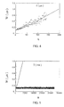
- the signal induced by the oscillating ion bunch on the charge-detecting element 5 can be characterized by its width and integral. Since the length of the stored bunch is larger than the length of the charge-detecting element 5, the width of the signal W (see Fig. 2A ) is proportional to the length of the stored ion bunch, and the integral of the signal is proportional to the number of ions in the bunch.
- ⁇ T may, in fact, be split into two components, both of which lead to the expansion of the ion bunch, but result from different factors.
- the first factor is the range of ion velocities ⁇ v in the bunch, which leads to a shorter oscillation time for faster moving ions than for slower ones and which is best represented by a spread or distribution about a mean value v.
- the size of this distribution mainly depends on the range of energies with which the ions enter the trap 1, and is due to the properties and mode of operation of the ion-producing source.
- Such a velocity spread yields a corresponding time spread for each oscillation of the bunch, which we denote as ⁇ T v .
- This component is a function of the key beam and field parameters.
- the second factor is the diversity of stable ion trajectories in the trap 1.
- the mirrors 2 and 3 of the trap like optical mirrors, have a certain amount of aberration, which results in some ions travelling a longer distance between the mirrors 2 and 3 than others.
- Ions travelling close to the optical axis 4 of the trap 1 have a slightly shorter oscillation period than ions travelling farther away from the axis 4.
- the time spread per oscillation due to this intrinsic property of the trap 1 is designated by ⁇ T a , and it also depends on the key beam and field parameters.
- ⁇ T a is, in general, the dominant one, but both can be estimated using a computer simulation program where the trajectories of the ions can be calculated by solving Newton's equation of motion under the influence of the electric field generated by the various voltages V B ,V C ,V D ,V E ,V G on the electrodes 2A-2H, 3A-3H. Since there exist more than one set of voltages V B ,V C ,V D ,V E ,V G applied to the electrodes 2A-2H, 3A-3H for which stable ion trajectories can be attained, it is possible to independently change both ⁇ T v and ⁇ T a to achieve different trapping states. This is done by choosing key beam and field parameters that result in various voltage gradients V B ,V C ,V D ,V E ,V G in the regions of the mirrors 2 and 3 of the trap 1.
- ⁇ T a and ⁇ T v key beam and field parameters should be chosen such as to reduce ⁇ T a and ⁇ T v .
- the reduction of ⁇ T a may be achieved by choosing a field configuration with a larger optical aberration, so that only those ions located close to the optical axis 4 of the trap 1 are trapped with stable trajectories. This reduces the value of ⁇ T a , and consequently ⁇ T, causing the local density of ions at the turning points of the ion trap 1 to be strongly increased, i.e. minimizing at these points, the distance between the ions comprised in the bunch.
- the key beam and field parameters are to be chosen to have compensation properties so that ions with slightly larger velocities will penetrate the mirror region 2,3 deeper, spending more time in that region than slower moving ions. This also minimizes the distances between the ions.
- experiments show that by adjusting the voltage gradient of the mirrors 2 and 3, such compensation can be achieved that the effect of the initial velocity distribution can be cancelled ( ⁇ T v ⁇ 0).
- ⁇ T a and ⁇ T v have to be adequately reduced, and the distance between the ions should be minimized and kept at this minimum until bunching occurs
- a computer can be programmed to give the optimal conditions necessary to achieve bunching. By allowing the average length of the bunch to be kept indefinitely constant, bunching significantly prolongs the possible measurement time of the bunch oscillation frequency, making the trap 1 capable of high-resolution mass spectrometry.
- the second approach is based on the mean field approximation, where the bunch of ions is represented by a homogeneously charged sphere with a diameter equivalent to the bunch length used in the experiment.
- the motion of a singly charged test particle in this case chosen to be an argon ion with an initial kinetic energy of 4.2 keV, is then monitored when it interacts with this sphere.
- the force between the test charge and the sphere is assumed to be the result of the homogeneous charge distribution, meaning that the force is zero if the test charge is located at the center of the sphere, and increases linearly until the distance of the test charge from the center is equal to the radius of the sphere.
- the force between the test charge and the sphere decreases with the square of the distance, as expected from Coulomb's law.
- the initial velocity of the sphere was chosen to be close, but not equal, to that of the test charge, and the two moved in a potential free region of about 200 mm, bounded by external potential walls which could be either linear or quadratic.
- the sphere reached the non-zero potential regions, its diameter was reduced smoothly in order to take into account the natural increase of density due to the velocity reduction, as happens in the trap 1.
- TOF-MS instruments have a resolution that is limited by the length of the free flight or central region 8.
- the ion trap 1 described above may be viewed as an extremely long time-of-flight mass spectrometer, which prevents bunch expansion. It is therefore capable of competing with the expensive and more sophisticated Fourier Transform Ion Cyclotron Resonance Mass Spectrometry (FTICR MS) instruments, where very high mass resolutions are obtained due to the long-time observation of the motion of ions in a uniform magnetic field, and to the independence of the measured frequency on the initial velocity distribution of the ions.
- the linear ion trap 1, when using bunching in accordance with the present invention may be used to achieve mass resolution comparable to the popular FTICR MS instruments.
- the ion trap 1 in the experiments was comprised of two identical mirrors 2 and 3, each in the form of a stack of eight, ring electrodes 2A-2H, 3A-3H, mounted on a rod assembly. The distances between the electrodes were measured to be 6 mm and the length of the trap was 407 mm. The central region 8 of the trap 1 was kept field free and at ground voltage. The voltages on the electrodes linearly increased from 2F to 2A in the entrance mirror 2, and from 3F to 3A in the opposing mirror 3. The electrodes 2F and 2H were grounded and together with the electrode 2G, which was maintained at a constant voltage V G , they operated as an asymmetric Einzel lens.
- the opposing mirror 3 had its electrodes 3F and 3H grounded, while 3G was maintained at the voltage V G , also constituting an asymmetric Einzel lens.
- the mirrors 2 and 3 confined the ions in the longitudinal direction, and the voltage V G on the Einzel lenses was chosen so that stable ion trajectories were achieved.
- the geometrical design of the ion trap and the voltage settings were developed using Simion 6.0, ion source computer software that gives ion trajectory simulations. To achieve a high vacuum, the trap 1 was pumped by a cryo pump at a rate of 2000 L/s and the internal pressure was maintained below 10 -9 Torr Further, a micro-channel plate detector 11 was mounted at one end of the trap 1, approximately 1.2 meters away from its center.
- a beam of Argon ions Ar + having an average initial kinetic energy of 4.2 keV was introduced into the trap 1 through one of its apertures 6A or 6B. At this energy, the oscillation frequency of the ion bunch in the trap 1 was about 340 kHz.
- the thin, annular charge-detecting element 5 having a length of 7 mm and a diameter of 18 mm, was mounted at the center of the trap 1. Ion bunches passing through this element 5 induced an image charge which was amplified by the low-noise charge-sensitive amplifier 12. The signal was then shaped and digitized by the detector 9, which was a digital oscilloscope, and Fourier transformed (FT) by the computer 13 to obtain a frequency spectrum. Examples of the observed signals are presented in Figs. 2A-2C and Figs. 3A-3C for different time windows after the introduction of a bunch containing about 10 5 Ar + ions into the trap 1.
- the bunch length was determined by the action of a fast electric chopper located upstream of the ion-producing source.
- the electron impact ion-producing source that was used gave a relatively narrow distribution of velocities ⁇ v estimated by the manufacturer to be ⁇ v/v ⁇ 0.1%.
- the storage lifetime was monitored by the micro-channel plate detector 11, which showed that the beam intensity decreases exponentially with time.
- the bunch length was measured as a function of time for two experiments having different field configurations.
- Figs. 2A-2C show the measured signal for three different time windows: between 100 and 115 ⁇ s after the initial injection of the bunch, between 300 and 315 ⁇ s thereafter, and between 80,000 and 80,015 ⁇ s thereafter, respectively. It is clear from Figs. 2A-2C that the signal broadens and disappears after a few hundred microseconds of trapping due to the expansion of the bunch. It is important to point out that the disappearance of this signal is not due to the finite lifetime of the ion beam 10 because of the residual gas pressure. In fact, this was monitored using the micro-channel plate detector 11, and was found to be of the order of 160,000 ⁇ s.
- Figs. 3A-3C show the observed signal for the three different time windows of 100 to 115 ⁇ s, 300 to 315 ⁇ s and 80,000 to 80,015 ⁇ s respectively. It is clear from Figs. 3A-3C that the signal remains present for a much longer time; the width W seems to remain constant, while the pulse height (or integral) is decreasing. This decrease is due to the loss of ions from the bunch caused by the collisions with the residual gas in the trap 1, for which a lifetime of 164 ms can be extracted by analyzing the time dependence of the pulse area.
- Fig. 5 shows the measured time evolution of the bunch length for the second experiment. It should be noted that the abscissa scale has been changed as compared to Fig. 4 in order to highlight the new conditions.
Landscapes
- Chemical & Material Sciences (AREA)
- Analytical Chemistry (AREA)
- Other Investigation Or Analysis Of Materials By Electrical Means (AREA)
- Analysing Materials By The Use Of Radiation (AREA)
- Crystals, And After-Treatments Of Crystals (AREA)
- Medicines Containing Plant Substances (AREA)
Applications Claiming Priority (3)
| Application Number | Priority Date | Filing Date | Title |
|---|---|---|---|
| US09/883,841 US6744042B2 (en) | 2001-06-18 | 2001-06-18 | Ion trapping |
| EP02738591A EP1402562B1 (fr) | 2001-06-18 | 2002-06-17 | Piegeage ionique |
| EP09000834A EP2099058A3 (fr) | 2001-06-18 | 2002-06-17 | Piège à ions |
Related Parent Applications (2)
| Application Number | Title | Priority Date | Filing Date |
|---|---|---|---|
| EP02738591.3 Division | 2002-06-17 | ||
| EP09000834.3 Division | 2009-01-22 |
Publications (2)
| Publication Number | Publication Date |
|---|---|
| EP2276056A2 true EP2276056A2 (fr) | 2011-01-19 |
| EP2276056A3 EP2276056A3 (fr) | 2011-01-26 |
Family
ID=25383441
Family Applications (3)
| Application Number | Title | Priority Date | Filing Date |
|---|---|---|---|
| EP09000834A Withdrawn EP2099058A3 (fr) | 2001-06-18 | 2002-06-17 | Piège à ions |
| EP10176305A Withdrawn EP2276056A3 (fr) | 2001-06-18 | 2002-06-17 | Piège à ions |
| EP02738591A Expired - Lifetime EP1402562B1 (fr) | 2001-06-18 | 2002-06-17 | Piegeage ionique |
Family Applications Before (1)
| Application Number | Title | Priority Date | Filing Date |
|---|---|---|---|
| EP09000834A Withdrawn EP2099058A3 (fr) | 2001-06-18 | 2002-06-17 | Piège à ions |
Family Applications After (1)
| Application Number | Title | Priority Date | Filing Date |
|---|---|---|---|
| EP02738591A Expired - Lifetime EP1402562B1 (fr) | 2001-06-18 | 2002-06-17 | Piegeage ionique |
Country Status (6)
| Country | Link |
|---|---|
| US (1) | US6744042B2 (fr) |
| EP (3) | EP2099058A3 (fr) |
| AT (1) | ATE422707T1 (fr) |
| DE (1) | DE60231118D1 (fr) |
| IL (1) | IL159044A0 (fr) |
| WO (1) | WO2002103747A1 (fr) |
Families Citing this family (73)
| Publication number | Priority date | Publication date | Assignee | Title |
|---|---|---|---|---|
| US6888130B1 (en) * | 2002-05-30 | 2005-05-03 | Marc Gonin | Electrostatic ion trap mass spectrometers |
| US6791078B2 (en) * | 2002-06-27 | 2004-09-14 | Micromass Uk Limited | Mass spectrometer |
| GB2394356B (en) * | 2002-08-05 | 2005-02-16 | Micromass Ltd | Mass spectrometer |
| US7071467B2 (en) * | 2002-08-05 | 2006-07-04 | Micromass Uk Limited | Mass spectrometer |
| GB0219072D0 (en) | 2002-08-16 | 2002-09-25 | Scient Analysis Instr Ltd | Charged particle buncher |
| GB0416288D0 (en) * | 2004-07-21 | 2004-08-25 | Micromass Ltd | Mass spectrometer |
| GB0513047D0 (en) * | 2005-06-27 | 2005-08-03 | Thermo Finnigan Llc | Electronic ion trap |
| US20070221862A1 (en) * | 2006-03-22 | 2007-09-27 | Wayne State University | Coupled Electrostatic Ion and Electron Traps for Electron Capture Dissociation - Tandem Mass Spectrometry |
| GB0607542D0 (en) | 2006-04-13 | 2006-05-24 | Thermo Finnigan Llc | Mass spectrometer |
| DE112007000931B4 (de) | 2006-04-13 | 2014-05-22 | Thermo Fisher Scientific (Bremen) Gmbh | Ionenenergiestreuungsreduzierung für ein Massenspektrometer |
| US7560716B2 (en) * | 2006-09-22 | 2009-07-14 | Virgin Islands Microsystems, Inc. | Free electron oscillator |
| US20080157007A1 (en) * | 2006-12-27 | 2008-07-03 | Varian Semiconductor Equipment Associates, Inc. | Active particle trapping for process control |
| US7608817B2 (en) * | 2007-07-20 | 2009-10-27 | Agilent Technologies, Inc. | Adiabatically-tuned linear ion trap with fourier transform mass spectrometry with reduced packet coalescence |
| US8334506B2 (en) | 2007-12-10 | 2012-12-18 | 1St Detect Corporation | End cap voltage control of ion traps |
| US7973277B2 (en) | 2008-05-27 | 2011-07-05 | 1St Detect Corporation | Driving a mass spectrometer ion trap or mass filter |
| CN101752179A (zh) * | 2008-12-22 | 2010-06-23 | 岛津分析技术研发(上海)有限公司 | 质谱分析器 |
| DE102009020886B4 (de) * | 2009-05-12 | 2012-08-30 | Bruker Daltonik Gmbh | Einspeichern von Ionen in Kíngdon-Ionenfallen |
| US8115165B2 (en) * | 2009-05-27 | 2012-02-14 | Dh Technologies Development Pte. Ltd. | Mass selector |
| GB2476964A (en) | 2010-01-15 | 2011-07-20 | Anatoly Verenchikov | Electrostatic trap mass spectrometer |
| GB2478300A (en) | 2010-03-02 | 2011-09-07 | Anatoly Verenchikov | A planar multi-reflection time-of-flight mass spectrometer |
| GB201022050D0 (en) | 2010-12-29 | 2011-02-02 | Verenchikov Anatoly | Electrostatic trap mass spectrometer with improved ion injection |
| GB201103361D0 (en) * | 2011-02-28 | 2011-04-13 | Shimadzu Corp | Mass analyser and method of mass analysis |
| GB2490958B (en) * | 2011-05-20 | 2016-02-10 | Thermo Fisher Scient Bremen | Method and apparatus for mass analysis |
| GB2495127B (en) | 2011-09-30 | 2016-10-19 | Thermo Fisher Scient (Bremen) Gmbh | Method and apparatus for mass spectrometry |
| CN103907171B (zh) | 2011-10-28 | 2017-05-17 | 莱克公司 | 静电离子镜 |
| GB201204817D0 (en) | 2012-03-19 | 2012-05-02 | Shimadzu Corp | A method of processing image charge/current signals |
| GB201304491D0 (en) | 2013-03-13 | 2013-04-24 | Shimadzu Corp | A method of processing image charge/current signals |
| CN105009251B (zh) | 2013-03-14 | 2017-12-22 | 莱克公司 | 多反射质谱仪 |
| WO2015150808A1 (fr) | 2014-04-01 | 2015-10-08 | Micromass Uk Limited | Analyseur de masse à cylindres coaxiaux à accélération orthogonale |
| GB201408392D0 (en) * | 2014-05-12 | 2014-06-25 | Shimadzu Corp | Mass Analyser |
| GB201507363D0 (en) | 2015-04-30 | 2015-06-17 | Micromass Uk Ltd And Leco Corp | Multi-reflecting TOF mass spectrometer |
| GB201520134D0 (en) | 2015-11-16 | 2015-12-30 | Micromass Uk Ltd And Leco Corp | Imaging mass spectrometer |
| GB201520130D0 (en) | 2015-11-16 | 2015-12-30 | Micromass Uk Ltd And Leco Corp | Imaging mass spectrometer |
| GB201520540D0 (en) | 2015-11-23 | 2016-01-06 | Micromass Uk Ltd And Leco Corp | Improved ion mirror and ion-optical lens for imaging |
| GB201613988D0 (en) | 2016-08-16 | 2016-09-28 | Micromass Uk Ltd And Leco Corp | Mass analyser having extended flight path |
| GB2567794B (en) | 2017-05-05 | 2023-03-08 | Micromass Ltd | Multi-reflecting time-of-flight mass spectrometers |
| GB2563571B (en) | 2017-05-26 | 2023-05-24 | Micromass Ltd | Time of flight mass analyser with spatial focussing |
| EP3662501A1 (fr) | 2017-08-06 | 2020-06-10 | Micromass UK Limited | Miroir ionique servant à des spectromètres de masse à réflexion multiple |
| EP3662503A1 (fr) | 2017-08-06 | 2020-06-10 | Micromass UK Limited | Injection d'ions dans des spectromètres de masse à passages multiples |
| US11295944B2 (en) | 2017-08-06 | 2022-04-05 | Micromass Uk Limited | Printed circuit ion mirror with compensation |
| US11081332B2 (en) | 2017-08-06 | 2021-08-03 | Micromass Uk Limited | Ion guide within pulsed converters |
| WO2019030473A1 (fr) | 2017-08-06 | 2019-02-14 | Anatoly Verenchikov | Champs servant à des sm tof à réflexion multiple |
| US11817303B2 (en) | 2017-08-06 | 2023-11-14 | Micromass Uk Limited | Accelerator for multi-pass mass spectrometers |
| US11211238B2 (en) | 2017-08-06 | 2021-12-28 | Micromass Uk Limited | Multi-pass mass spectrometer |
| WO2019060538A1 (fr) | 2017-09-20 | 2019-03-28 | The Trustees Of Indiana University | Procédés de résolution de lipoprotéines par spectrométrie de masse |
| EP3738137A1 (fr) | 2018-01-12 | 2020-11-18 | The Trustees of Indiana University | Conception de piège à ions linéaire électrostatique pour spectrométrie de masse à détection de charge |
| GB201802917D0 (en) | 2018-02-22 | 2018-04-11 | Micromass Ltd | Charge detection mass spectrometry |
| GB201806507D0 (en) | 2018-04-20 | 2018-06-06 | Verenchikov Anatoly | Gridless ion mirrors with smooth fields |
| GB201807626D0 (en) | 2018-05-10 | 2018-06-27 | Micromass Ltd | Multi-reflecting time of flight mass analyser |
| GB201807605D0 (en) | 2018-05-10 | 2018-06-27 | Micromass Ltd | Multi-reflecting time of flight mass analyser |
| GB201808530D0 (en) | 2018-05-24 | 2018-07-11 | Verenchikov Anatoly | TOF MS detection system with improved dynamic range |
| WO2019236139A1 (fr) | 2018-06-04 | 2019-12-12 | The Trustees Of Indiana University | Interface pour transporter des ions d'un environnement à pression atmosphérique à un environnement à basse pression |
| WO2019236143A1 (fr) * | 2018-06-04 | 2019-12-12 | The Trustees Of Indiana University | Appareil et procédé d'étalonnage ou de réinitialisation d'un détecteur de charge |
| EP4391015A3 (fr) | 2018-06-04 | 2024-10-09 | The Trustees of Indiana University | Réseau de piège à ions pour spectrométrie de masse à détection de charge à haut débit |
| JP7398810B2 (ja) | 2018-06-04 | 2023-12-15 | ザ・トラスティーズ・オブ・インディアナ・ユニバーシティー | 静電線形イオン・トラップにイオンを捕獲する装置および方法 |
| CA3100838A1 (fr) | 2018-06-04 | 2019-12-12 | The Trustees Of Indiana University | Spectrometrie de masse a detection de charge avec analyse en temps reel et optimisation de signal |
| GB201810573D0 (en) | 2018-06-28 | 2018-08-15 | Verenchikov Anatoly | Multi-pass mass spectrometer with improved duty cycle |
| CN113574632B (zh) | 2018-11-20 | 2024-07-30 | 印地安纳大学理事会 | 用于单粒子质谱分析的轨道阱 |
| EP4443473A3 (fr) | 2018-12-03 | 2025-01-01 | The Trustees of Indiana University | Appareil d'analyse simultanée de multiples ions avec un piège à ions linéaire électrostatique |
| GB201901411D0 (en) | 2019-02-01 | 2019-03-20 | Micromass Ltd | Electrode assembly for mass spectrometer |
| GB201903779D0 (en) | 2019-03-20 | 2019-05-01 | Micromass Ltd | Multiplexed time of flight mass spectrometer |
| EP3959741A1 (fr) | 2019-04-23 | 2022-03-02 | The Trustees of Indiana University | Identification de sous-espèces d'échantillon sur la base d'un comportement de charge de particules dans des conditions d'échantillon induisant un changement structural |
| WO2021061650A1 (fr) | 2019-09-25 | 2021-04-01 | The Trustees Of Indiana University | Appareil et procédé d'exécution d'une spectrométrie de masse à détection de charge en mode pulsé |
| CN114728237B (zh) | 2019-10-10 | 2026-02-24 | 印地安纳大学理事会 | 用于识别、选择和纯化粒子的系统和方法 |
| JP7690209B2 (ja) | 2019-12-18 | 2025-06-10 | ザ・トラスティーズ・オブ・インディアナ・ユニバーシティー | 電荷測定装置を有する質量分析計 |
| EP4100991B1 (fr) | 2020-02-03 | 2025-01-29 | The Trustees of Indiana University | Spectromètre de masse à détection de charge et procédé associé |
| WO2021207494A1 (fr) | 2020-04-09 | 2021-10-14 | Waters Technologies Corporation | Détecteur d'ions |
| GB2595480A (en) | 2020-05-27 | 2021-12-01 | Shimadzu Corp | Improvements in and relating to time-frequency analysis |
| US20240290597A1 (en) | 2021-06-15 | 2024-08-29 | Shimadzu Corporation | Improvements in and relating to ion analysis |
| JP7616436B2 (ja) | 2021-06-15 | 2025-01-17 | 株式会社島津製作所 | イオン分析における及びイオン分析に関する改良 |
| CN113952637B (zh) * | 2021-09-29 | 2022-09-06 | 清华大学 | 一种实现束团分离的方法和装置 |
| CN118402037A (zh) | 2021-12-15 | 2024-07-26 | 水技术公司 | 具有集成放大器的感应式检测器 |
| WO2023139351A1 (fr) * | 2022-01-18 | 2023-07-27 | Micromass Uk Limited | Spectromètre de masse |
Citations (1)
| Publication number | Priority date | Publication date | Assignee | Title |
|---|---|---|---|---|
| US5880466A (en) | 1997-06-02 | 1999-03-09 | The Regents Of The University Of California | Gated charged-particle trap |
Family Cites Families (4)
| Publication number | Priority date | Publication date | Assignee | Title |
|---|---|---|---|---|
| DE3025764C2 (de) * | 1980-07-08 | 1984-04-19 | Hermann Prof. Dr. 6301 Fernwald Wollnik | Laufzeit-Massenspektrometer |
| US5689111A (en) * | 1995-08-10 | 1997-11-18 | Analytica Of Branford, Inc. | Ion storage time-of-flight mass spectrometer |
| DE4408489C2 (de) | 1994-03-14 | 1997-07-31 | Frank Dr Strehle | Massenspektrometer |
| US6013913A (en) * | 1998-02-06 | 2000-01-11 | The University Of Northern Iowa | Multi-pass reflectron time-of-flight mass spectrometer |
-
2001
- 2001-06-18 US US09/883,841 patent/US6744042B2/en not_active Expired - Fee Related
-
2002
- 2002-06-17 DE DE60231118T patent/DE60231118D1/de not_active Expired - Lifetime
- 2002-06-17 AT AT02738591T patent/ATE422707T1/de not_active IP Right Cessation
- 2002-06-17 WO PCT/IL2002/000468 patent/WO2002103747A1/fr not_active Ceased
- 2002-06-17 IL IL15904402A patent/IL159044A0/xx unknown
- 2002-06-17 EP EP09000834A patent/EP2099058A3/fr not_active Withdrawn
- 2002-06-17 EP EP10176305A patent/EP2276056A3/fr not_active Withdrawn
- 2002-06-17 EP EP02738591A patent/EP1402562B1/fr not_active Expired - Lifetime
Patent Citations (1)
| Publication number | Priority date | Publication date | Assignee | Title |
|---|---|---|---|---|
| US5880466A (en) | 1997-06-02 | 1999-03-09 | The Regents Of The University Of California | Gated charged-particle trap |
Also Published As
| Publication number | Publication date |
|---|---|
| US6744042B2 (en) | 2004-06-01 |
| US20020190200A1 (en) | 2002-12-19 |
| EP2099058A3 (fr) | 2009-12-02 |
| DE60231118D1 (de) | 2009-03-26 |
| EP2276056A3 (fr) | 2011-01-26 |
| IL159044A0 (en) | 2004-05-12 |
| WO2002103747A1 (fr) | 2002-12-27 |
| ATE422707T1 (de) | 2009-02-15 |
| EP1402562B1 (fr) | 2009-02-11 |
| EP1402562A1 (fr) | 2004-03-31 |
| EP2099058A2 (fr) | 2009-09-09 |
Similar Documents
| Publication | Publication Date | Title |
|---|---|---|
| US6744042B2 (en) | Ion trapping | |
| EP2442351B1 (fr) | Spectromètre de masse | |
| EP1629519B1 (fr) | Procede et appareil de spectrometrie de masse en tandem pour obtenir un spectre complet pour toutes les masses | |
| JP3990889B2 (ja) | 質量分析装置およびこれを用いる計測システム | |
| US7425699B2 (en) | Mass spectrometry method and apparatus | |
| JP5322385B2 (ja) | 質量分析器におけるイオン集団の制御 | |
| US7060987B2 (en) | Electron ionization source for othogonal acceleration time-of-flight mass spectrometry | |
| JP4263607B2 (ja) | 四重極イオントラップ装置、四重極イオントラップ装置を動作させる方法、および四重極イオントラップ装置を含む質量分析装置 | |
| DE112010005660T5 (de) | lonenfallen-Massenspektrometer | |
| GB2470259A (en) | Introducing ions into Kingdon ion traps | |
| DE102011109927B4 (de) | Einführung von Ionen in Kingdon-Ionenfallen | |
| US7372021B2 (en) | Time-of-flight mass spectrometer combining fields non-linear in time and space | |
| CA2689091C (fr) | Procede et appareil pour realiser une spectrometrie de masse | |
| JP2006093160A (ja) | 質量分析装置およびこれを用いる計測システム | |
| Lemière | Mass analysers for LC-MS | |
| WO2003107387A1 (fr) | Spectrometre de masse a temps de vol non lineaire | |
| Amad et al. | Mass resolution of 11,000 to 22,000 with a multiple pass quadrupole mass analyzer | |
| WO2003103008A1 (fr) | Spectrometre de masse a temps de vol combinant des champs non lineaires dans le temps et l'espace |
Legal Events
| Date | Code | Title | Description |
|---|---|---|---|
| PUAI | Public reference made under article 153(3) epc to a published international application that has entered the european phase |
Free format text: ORIGINAL CODE: 0009012 |
|
| PUAL | Search report despatched |
Free format text: ORIGINAL CODE: 0009013 |
|
| AC | Divisional application: reference to earlier application |
Ref document number: 1402562 Country of ref document: EP Kind code of ref document: P Ref document number: 2099058 Country of ref document: EP Kind code of ref document: P |
|
| AK | Designated contracting states |
Kind code of ref document: A2 Designated state(s): AT BE CH CY DE DK ES FI FR GB GR IE IT LI LU MC NL PT SE TR |
|
| AK | Designated contracting states |
Kind code of ref document: A3 Designated state(s): AT BE CH CY DE DK ES FI FR GB GR IE IT LI LU MC NL PT SE TR |
|
| RIN1 | Information on inventor provided before grant (corrected) |
Inventor name: ZAJFMAN, DANIEL Inventor name: SAGI, IRIT Inventor name: RAPPAPORT, MICHAEL Inventor name: PEDERSEN, HENRIK B. Inventor name: RUDICH, YINON Inventor name: HEBER, ODED |
|
| STAA | Information on the status of an ep patent application or granted ep patent |
Free format text: STATUS: THE APPLICATION IS DEEMED TO BE WITHDRAWN |
|
| 18D | Application deemed to be withdrawn |
Effective date: 20110727 |