EP2276097A1 - Lithiumionenbatterie und elektrodenwicklungselement für eine lithiumionenbatterie - Google Patents
Lithiumionenbatterie und elektrodenwicklungselement für eine lithiumionenbatterie Download PDFInfo
- Publication number
- EP2276097A1 EP2276097A1 EP09746594A EP09746594A EP2276097A1 EP 2276097 A1 EP2276097 A1 EP 2276097A1 EP 09746594 A EP09746594 A EP 09746594A EP 09746594 A EP09746594 A EP 09746594A EP 2276097 A1 EP2276097 A1 EP 2276097A1
- Authority
- EP
- European Patent Office
- Prior art keywords
- tape
- lithium ion
- ion battery
- vinylidene fluoride
- aromatic polyester
- Prior art date
- Legal status (The legal status is an assumption and is not a legal conclusion. Google has not performed a legal analysis and makes no representation as to the accuracy of the status listed.)
- Granted
Links
Images


Classifications
-
- H—ELECTRICITY
- H01—ELECTRIC ELEMENTS
- H01M—PROCESSES OR MEANS, e.g. BATTERIES, FOR THE DIRECT CONVERSION OF CHEMICAL ENERGY INTO ELECTRICAL ENERGY
- H01M10/00—Secondary cells; Manufacture thereof
- H01M10/05—Accumulators with non-aqueous electrolyte
- H01M10/058—Construction or manufacture
- H01M10/0587—Construction or manufacture of accumulators having only wound construction elements, i.e. wound positive electrodes, wound negative electrodes and wound separators
-
- H—ELECTRICITY
- H01—ELECTRIC ELEMENTS
- H01M—PROCESSES OR MEANS, e.g. BATTERIES, FOR THE DIRECT CONVERSION OF CHEMICAL ENERGY INTO ELECTRICAL ENERGY
- H01M10/00—Secondary cells; Manufacture thereof
- H01M10/04—Construction or manufacture in general
- H01M10/0431—Cells with wound or folded electrodes
-
- H—ELECTRICITY
- H01—ELECTRIC ELEMENTS
- H01M—PROCESSES OR MEANS, e.g. BATTERIES, FOR THE DIRECT CONVERSION OF CHEMICAL ENERGY INTO ELECTRICAL ENERGY
- H01M10/00—Secondary cells; Manufacture thereof
- H01M10/05—Accumulators with non-aqueous electrolyte
- H01M10/052—Li-accumulators
- H01M10/0525—Rocking-chair batteries, i.e. batteries with lithium insertion or intercalation in both electrodes; Lithium-ion batteries
-
- H—ELECTRICITY
- H01—ELECTRIC ELEMENTS
- H01M—PROCESSES OR MEANS, e.g. BATTERIES, FOR THE DIRECT CONVERSION OF CHEMICAL ENERGY INTO ELECTRICAL ENERGY
- H01M50/00—Constructional details or processes of manufacture of the non-active parts of electrochemical cells other than fuel cells, e.g. hybrid cells
- H01M50/10—Primary casings; Jackets or wrappings
- H01M50/102—Primary casings; Jackets or wrappings characterised by their shape or physical structure
- H01M50/107—Primary casings; Jackets or wrappings characterised by their shape or physical structure having curved cross-section, e.g. round or elliptic
-
- Y—GENERAL TAGGING OF NEW TECHNOLOGICAL DEVELOPMENTS; GENERAL TAGGING OF CROSS-SECTIONAL TECHNOLOGIES SPANNING OVER SEVERAL SECTIONS OF THE IPC; TECHNICAL SUBJECTS COVERED BY FORMER USPC CROSS-REFERENCE ART COLLECTIONS [XRACs] AND DIGESTS
- Y02—TECHNOLOGIES OR APPLICATIONS FOR MITIGATION OR ADAPTATION AGAINST CLIMATE CHANGE
- Y02E—REDUCTION OF GREENHOUSE GAS [GHG] EMISSIONS, RELATED TO ENERGY GENERATION, TRANSMISSION OR DISTRIBUTION
- Y02E60/00—Enabling technologies; Technologies with a potential or indirect contribution to GHG emissions mitigation
- Y02E60/10—Energy storage using batteries
-
- Y—GENERAL TAGGING OF NEW TECHNOLOGICAL DEVELOPMENTS; GENERAL TAGGING OF CROSS-SECTIONAL TECHNOLOGIES SPANNING OVER SEVERAL SECTIONS OF THE IPC; TECHNICAL SUBJECTS COVERED BY FORMER USPC CROSS-REFERENCE ART COLLECTIONS [XRACs] AND DIGESTS
- Y02—TECHNOLOGIES OR APPLICATIONS FOR MITIGATION OR ADAPTATION AGAINST CLIMATE CHANGE
- Y02P—CLIMATE CHANGE MITIGATION TECHNOLOGIES IN THE PRODUCTION OR PROCESSING OF GOODS
- Y02P70/00—Climate change mitigation technologies in the production process for final industrial or consumer products
- Y02P70/50—Manufacturing or production processes characterised by the final manufactured product
Definitions
- the present invention relates to an improvement of a lithium ion battery of the type wherein a wound electrode structure formed by winding a laminate of a tape-form negative electrode and a tape-form positive electrode together with a tape-form separator interposed therebetween is sealed up together with a non-aqueous electrolytic solution within a battery case so as to prevent unwinding of the wound electrode structure, and also an improvement of the wound electrode structure sealed up within such a lithium ion battery.
- an unwinding prevention tape comprising a polyolefin, such as polyethylene and polypropylene, surrounding and adhering to the wound electrode structure as a means for preventing unwinding of the wound electrode structure.
- the thus-formed wound electrode body is inserted into a battery case having an inside diameter almost exactly fitting about the wound electrode body, and is enclosed in the battery case together with a nonaqueous electrolytic solution subsequently injected therein.
- polyolefin such as polyethylene
- polyethylene has little affinity to a nonaqueous electrolytic solution and remarkably obstructs the injection of the nonaqueous electrolytic solution into the battery case after the insertion of the wound electrode body to impregnate the wound electrode structure with the nonaqueous electrolytic solution.
- it also impairs the workability of the insertion per se of the wound electrode body into the battery case having an inside diameter close to the outside diameter of the wound electrode body.
- an unwinding prevention tape comprising vinylidene fluoride resin per se having a good affinity with a nonaqueous electrolytic solution
- Patent document 2 an unwinding prevention tape comprising vinylidene fluoride resin per se having a good affinity with a nonaqueous electrolytic solution
- the nonaqueous electrolytic solution injected after the insertion thereof can promptly impregnate the wound electrode structure, and also the unwinding prevention tape swells by the impregnation with the nonaqueous electrolytic solution to have an increased thickness so that a somewhat larger gap is permitted between the wound electrode body and the battery case at the time of the insertion of the wound electrode body to the battery case, whereby the insertion work becomes remarkably easier.
- a principal object of the present invention is to provide a lithium ion battery having inserted therein a wound electrode body formed by attaching an unwinding prevention tape capable of exhibiting stable unwinding prevention ability even under a high-temperature operating condition to the circumference thereof, and also such a wound electrode body for lithium ion batteries.
- the present inventors have examined various resins, particularly in order to find a thermoplastic resin having good affinity or miscibility with vinylidene fluoride resin, unlike polyolefin, etc. and, as a result thereof, have found that an aromatic polyester resin is the most suited for such an object and that the use of an unwinding prevention tape comprising a composite material (a blend or a laminate) of a vinylidene fluoride resin and an aromatic polyester resin, thus obtained, is very effective in achievement of the above-mentioned object of the present invention.
- the present invention provides a lithium ion battery, comprising : a battery case; and a wound electrode body formed by attaching an unwinding prevention tape to a circumference of a wound electrode structure which is formed by winding a laminate of a tape-form negative electrode and a tape-form positive electrode together with a tape-form separator interposed therebetween, and a non-aqueous electrolytic solution, sealed up together within the battery case; wherein unwinding prevention tape comprises a composite material of a vinylidene fluoride resin and an aromatic polyester resin.
- the present invention further provides a wound electrode body for a lithium ion battery, formed by attaching an unwinding prevention tape to a circumference of a wound electrode structure which is formed by winding a laminate of a tape-form negative electrode and a tape-form positive electrode together with a tape-form separator interposed therebetween; wherein the unwinding prevention tape comprises a composite material of a vinylidene fluoride resin and an aromatic polyester resin.
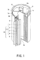
- the lithium ion battery basically has a structure including a wound electrode body 15 formed by attaching an unwinding prevention tape 5 onto a circumference of a wound electrode structure (generator element) 14 which in turn has been formed by winding in a vertex form a laminate of a positive electrode 1, a separator 2, a negative electrode 3 and a separator 4, each in a tape or strip form and disposed in this order, accommodated within a battery case 6 having a bottom (on which an insulating sheet (not shown) has been disposed in advance) functioning as a negative electrode terminal 6a.
- a wound electrode body 15 formed by attaching an unwinding prevention tape 5 onto a circumference of a wound electrode structure (generator element) 14 which in turn has been formed by winding in a vertex form a laminate of a positive electrode 1, a separator 2, a negative electrode 3 and a separator 4, each in a tape or strip form and disposed in this order, accommodated within a battery case 6 having a bottom (on which an insulating
- the negative electrode 3 is further electrically connected to the negative electrode terminal (battery case bottom) 6a via a negative electrode lead (3a of Fig. 2 ) which extends piercing through the above-mentioned insulating sheet (not shown) disposed on the bottom, and at the top thereof, a spacer (insulating sheet) 7a, a gasket 7b and a safety valve 8 are disposed, and thereover a top plate (battery lid) 9 having a crown 9a electrically connected to the positive electrode 1 via a positive electrode lead 1a and functioning as a positive electrode terminal is disposed.
- the entire structure is sealed by crimping a top rim 6b of the battery case 6.
- a nonaqueous electrolytic solution is injected into and accommodated in the battery case 6 in a form of impregnating the separators 2, 4 and the electrodes 1, 3, in particular.
- the positive electrode 1 and the negative electrode 3, may respectively be formed by coating at least one surface of an electroconductive substrate comprising a foil or net of a metal, such as iron, stainless steel, steel, copper, aluminum or nickel and having a thickness of 5 -100 ⁇ m, preferably 5 - 20 ⁇ m, with an electrode-forming slurry composition obtained by mixing an active substance, an optionally added electroconductive aid, such as carbon black, and a solution of a binder such as vinylidene fluoride resin or an emulsion of a rubber-type binder such as SBR (styrene-butadiene rubber), followed by drying at, e.g. 50 - 170°C, to form an electrode layer in a dry thickness of 10 - 1000 ⁇ m.
- a metal such as iron, stainless steel, steel, copper, aluminum or nickel and having a thickness of 5 -100 ⁇ m, preferably 5 - 20 ⁇ m
- an electrode-forming slurry composition obtained by mixing an active substance, an optionally added electroconductive aid
- LiMY 2 wherein M represents at least one species of transition metals, such as Co, Ni, Fe, Mn, Cr, and V; Y represents a chalcogen element, such as O and S
- a composite metal oxide such as a composite metal oxide including those represented by LiNi x
- a negative electrode it is possible to use powdery carbonaceous materials, such as graphite, activated carbon and calcination-and-carbonization products of a phenolic resin, pitch, etc., and in addition thereto, metal oxides, such as GeO, GeO 2 , SnO, SnO 2 , PbO, and PbO 2, , and composite metal oxides of these (for example, those disclosed in JP-A 7-249409 ).
- nonaqueous electrolytic solution impregnating the separators 2 , 4, etc it is possible to use a solution of an electrolyte, such as a lithium salt, in a nonaqueous solvent (organic solvent).
- the electrolyte may, for example, comprise LiPF 6 , LiAsF 6 , LiClO 4 , LiBF 4 , CH 3 SO 3 Li, CF 3 SO 3 Li, LiCl, LiBr, etc.
- organic solvents for electrolytes it is possible to use, e.g., propylene carbonate, ethylene carbonate, 1,2-dimethoxy ethane, 1,2-diethoxyethane, dimethyl carbonate, diethyl carbonate, ethyl methyl carbonate, gamma-butyrolactone, methyl propionate, ethyl propionate, mixture solvents of these, etc., but these are not exhaustive.
- the separators 2 and 4 may comprise a fine porous membrane of polymers, such as polyolefin, and also nonwoven fabric and other porous materials.
- the thickness is about 10-50 ⁇ m, for example.
- a wound electrode structure (power generation element) 14 comprising a laminate formed by alternately winding such electrodes 1, 3 and separators 2, 4, an unwinding prevention tape 5 comprising a composite material of a vinylidene fluoride resin and an aromatic polyester resin is attached, thereby forming a wound electrode body 15.
- Fig. 2 is a schematic perspective view of an example of such a wound electrode body 15 formed in this way and also shows a positive electrode lead 1a which is an extended portion of the electroconductive substrate of the positive electrode 1 and a negative electrode lead 3a which is an extended portion of the electroconductive substrate of the negative electrode 3.
- the unwinding prevention tape 5 can be provided with minute perforations (not shown in particular) formed by needle punching etc., so as to promote the penetration of a nonaqueous electrolytic solution.
- minute perforations not shown in particular
- 1 or 2 turns, particularly 1 turn, of winding can effectively exhibit the unwinding prevention action for the wound electrode structure 14 through a thickness increase owing to swelling after insertion into the battery case and injection of the nonaqueous electrolytic solution, unlike the conventional polyolefin-based unwinding prevention tape having required about 3 turns of winding.
- the entire shape of the lithium ion battery of the present invention can also be formed in a rectangular shape as far as it is of an electrode-winding type.
- layer structure of the unwinding prevention tape used by the present invention are described with reference to thicknesswise partial schematic sectional views.
- the unwinding prevention tape 5 of the above-mentioned wound electrode body 15 is formed of a composite material of vinylidene fluoride resin and aromatic polyester resin.
- the types of the composite mainly include a blend and a laminate.
- the simplest structure of the unwinding prevention tape 5 used in the present invention consists of a single layer 51 comprising a blend as shown in Fig. 3 , , and the simplest laminate structure is a laminate of one layer 52 of vinylidene fluoride resin and one layer 53 of aromatic polyester resin as shown in Fig. 4 .
- Fig. 4 with a layer of a blend of vinylidene fluoride resin and aromatic polyester resin, and it is also possible to use a structure as shown in Fig. 5 comprising a single vinylidene fluoride resin layer 52 sandwiched between two layers 53 of aromatic polyester resin, or a structure as shown in Fig. 6 comprising a single aromatic polyester resin layer 53 between two layers 52 of vinylidene fluoride resin.
- the vinylidene fluoride resin used in the present invention may be either a homopolymer or a copolymer of vinylidene fluoride.
- the vinylidene fluoride copolymer may include: copolymers of vinylidene fluoride with other monomers copolymerizable with the vinylidene fluoride, inclusive of: hydrocarbon monomers, such as ethylene and propylene, and fluorine-containing monomers other than vinylidene fluoride, such as vinyl fluoride, trifluoroethylene, trifluorochloroethylene, tetrafluoroethylene, hexafluoropropylene, and fluoroalkyl vinyl ethers.
- the copolymer may preferably contain 90 mol % or more, particularly 95 mol % or more, of vinylidene fluoride units.
- the vinylidene fluoride resin it is also preferred to copolymerize 100 wt. parts of the above-mentioned monomer(s) providing the homopolymer or copolymer of vinylidene fluoride with 0.1-3 wt. parts of a monomer having at least one adhesive functional group selected from carboxyl group, epoxy group, hydroxyl group and carbonyl group, and copolymerizable with vinylidene fluoride, to provide a vinylidene fluoride (co)polymer modified by introducing such an adhesive functional group.
- Examples of the carboxyl group-containing monomer may include: unsaturated monobasic acids, such as acrylic acid and crotonic acid, and unsaturated dibasic acids, such as maleic acid and citraconic acid, or mono-alkyl esters thereof.
- Examples of the epoxy group-containing monomer may include: allyl glycidyl ether, methallyl glycidyl ether, glycidyl crotonate, glycidyl allylacetate, etc.
- the hydroxyl group-containing monomer may include: hydroxyethyl acrylate, hydroxypropyl acrylate, etc.
- the carbonyl group-containing monomer may include: ethylene carbonate, etc.
- Such an adhesive functional group-containing monomer is used only in a small amount of 0.1 to 3 wt. parts per 100 wt. parts of vinylidene fluoride (co)polymer-forming monomer having no adhesive functional group, so that it can be subjected to suspension polymerization in an aqueous medium together with the vinylidene fluoride (co)polymer-forming monomer.
- a crosslinking structure to the vinylidene fluoride (co)polymer by a chemical cross-linking method (addition of a polyamine, a polyol or a polyfunctional crosslinking agent, and a radical generator) or a physical cross-linking method (exposure to electron rays or gamma rays).
- a vinylidene fluoride resin having an inherent viscosity ( ⁇ inth , referring to a logarithmic viscosity at 30 °C of a solution of 4g of the resin in 1 liter of N, N-dimethylformamide, herein) of 0.8 to 1.3 dl/g, particularly 0.85 - 1.1 dl/g, among the above-mentioned class.
- the aromatic polyester resin forming the composite material with the above-mentioned vinylidene fluoride resin means a polyester formed of a diol and a dicarboxylic acid, at least one of which, preferably the dicarboxylic acid, is aromatic.
- Preferred examples of the aromatic polyester resin may include: polyethylene terephthalate, polybutylene terephthalate, polyethylene naphthalate, and polybutylene naphthalate.
- the diol in order to improve the affinity with the vinylidene fluoride resin, it is also preferred to replace a portion of the diol with another diol component, such as 1,4-cyclohexanedimethanol (CHDM), or to replace a portion of the carboxylic acid, e.g., terephthalic acid with isophthalic acid, to reduce the crystallinity.
- CHDM 1,4-cyclohexanedimethanol
- an excessive replacement should be avoided, since it obstructs the effect of improving the heat resistance of the unwinding prevention tape in the nonaqueous electrolytic solution expected to be attained by use of the aromatic polyester resin.
- IV intrinsic viscosity
- the embodiments of the compositing for providing the composite of vinylidene fluoride resin and aromatic polyester resin forming the unwinding prevention tape of the present invention are roughly divided into blend (or mixture) and laminate.
- blend or mixture
- laminate the mutual solubility of both resins is restricted to some extent, so that a weight ratio of vinylidene fluoride resin : aromatic polyester resin in the range of 40:60-60:40 should be avoided.
- a weight ratio of vinylidene-fluoride resin : aromatic polyester resin of 95:5 - 5:95.
- the weight ratio of vinylidene fluoride resin : aromatic polyester resin should preferably be in a range of 95:5-60:40, most preferably 95:5-70:30.
- the laminate has advantages of higher safety and more stable physical property since it surely includes a heat-resistant layer (non-swelling layer).
- the blend embodiment is advantageous in that it allows a simpler tape-manufacturing apparatus; it provides a curl-free unwinding prevention tape; and it can be used without any discrimination between the front and back surfaces.
- the unwinding prevention tape may suitably have a total thickness per sheet of about 20-70 ⁇ m, preferably about 30-60 ⁇ m and can have been stretched uniaxially or biaxially, as desired, for the purpose of , e.g., providing an improved strength and adjusting the thickness.
- the unwinding prevention tape 5 of the present invention is disposed in attachment to the separator 4 as the outermost layer of the wound electrode structure 14. Accordingly, the unwinding prevention tape 5 can be attached to the circumference of the wound electrode structure 14 to prevent the unwinding of the wound electrode structure 14 by using the sealability of, e.g., polyolefin forming the separator 4 by heat sealing or ultrasonic sealing. More, conveniently, however, it is preferred to apply an adhesive on a surface a layer of the unwinding prevention tape 5 (preferably the aromatic polyester resin layer 53 or an aromatic polyester resin-rich blend layer, in the case of the laminate embodiment) attached to the wound electrode structure 14, to form an adhesion-type unwinding prevention tape.
- FIG. 9 are thickness-wise schematic sectional views of such adhesion-type unwinding prevention tapes 5A formed by disposing a pressure-sensitive adhesive layer 55 on the side (the lower side in the figures) attached to the wound electrode structure 14 of the unwinding prevention tapes of Fig. 3 - Fig. 5 , respectively.
- any type of pressure-sensitive adhesive can be used for the layer 55 without restriction, as far as it sticks to the separator layer.
- various pressure-sensitive adhesives such as those of polyisoprene base, styrene-butadiene random copolymer base, styrene-isoprene block copolymer base, isobutylene-isoprene rubber base, polyisobutylene base, acrylic resin base, and silicone base.
- These pressure-sensitive adhesives can be easily obtained as commercial products. Suitable adhesion strength may be selected depending on the material of the separator.
- the coating method of applying the pressure-sensitive adhesive coating liquid on the surface of the unwinding prevention tape is not particularly limited, and it is possible to use dipping, spraying, coaters, and printers therefor.
- the coater may include: an air knife coater, a blade coater, a reverse roll coater, a gravure coater, a bar coater, etc.
- the coating liquid may be dried according to any drying method without particular restriction, inclusive of, e.g., natural drying, a method of using a dryer set to a predetermined temperature, or a method of using an attached dryer for the coater.
- the drying temperature may, for example, be 50-120 °C in the case of hot-air drying.
- Time of drying may be suitably selected depending on the coating method.
- the pressure-sensitive adhesive layer 55 formed in about 10-30 ⁇ m as a dry thickness.
- the unwinding prevention tapes (films) produced in the above-mentioned Examples were respectively subjected to measurement of heat resistance (visual appearance observation), thickness, rate of thickness increase and rate of weight increase as follows. More specifically, each of the films produced in the above-mentioned Examples, was cut into a 2 cm-wide and 4 cm-long sample, of which the thickness and weight were then measured.
- each sample was sandwiched with slide glasses and placed in an autoclave, into which was then injected a mixture of an electrolytic solution (a liquid mixture of ethylene carbonate (EC), propylene carbonate (PC) and dimethyl carbonate (DMC) in volume ratios of 16/8/76) and 1.0 mol/L of LiPF 6 as an electrolyte, and the autoclave was sealed.
- an electrolytic solution a liquid mixture of ethylene carbonate (EC), propylene carbonate (PC) and dimethyl carbonate (DMC) in volume ratios of 16/8/76) and 1.0 mol/L of LiPF 6 as an electrolyte
- the autoclave was held for 16 hours in an oven at 90 °Cand taken out after cooling to room temperature.
- the sample was taken out of the autoclave, after wiping off the attached electrolytic solution, was subjected to visual observation, and measurement of thickness and rate of weight increase.
- the thickness measurement was performed by using a planar head gauge (of 8.5 mm in diameter) under a load of 1.5 N.
- the results of the visual observation were evaluate with the standard of X : Sample caused crack and a large degree of whitening, and O : Sample caused no crack and little whitening.
- the film of Comparative Example 3 using polybutylene terephthalate (PBT) alone was very deficient in swellability while caused very little deterioration in appearance, so that no advantage was conceived in comparison with a polyolefin unwinding prevention tape.
- PET aromatic polyethylene terephthalate
- a two-layer film was obtained in a similar manner as in Production Example 10 except using polymethyl methacrylate (PMMA; "HBY-N19", made by Mitsubishi Rayon Co., Ltd.) instead of PBT.
- PMMA polymethyl methacrylate
- HBY-N19 made by Mitsubishi Rayon Co., Ltd.
- a two-layer film was obtained in a similar manner as in Production Example 10 except for using polypropylene (PP; "NOVATEC FY6H", made by Japan Polypropylene Corporation) instead of PBT.
- PP polypropylene
- NOVATEC FY6H made by Japan Polypropylene Corporation
- the film of Comparative Example 5 using polypropylene (PP) instead of aromatic polyester resin showed no or very weak adhesion at the boundary with PVDF, so that it caused peeling between the layers during the preparation and handling (such as cutting and lamination) thereafter, thus showing very poor workability and unsuitability for commercial use.
- PP polypropylene
- Petroleum pitch was used as a starting material and subjected to introduction of 10-20 wt. % of a functional group containing oxygen (so-called oxygen crosslinkage) and calcination at 1000 °C while flowing an inert gas stream to obtain a nearly glassy carbon, which showed a (002) plane spacing of 3.76 ⁇ as a result of X-ray diffraction measurement and a true specific gravity of 1.58 g/cm 3 as measured by a picnometer.
- the carbon material was pulverized to obtain a powdery carbon material with a mean particle diameter of 10 ⁇ m, which was used as a negative-electrode active material. Then, 10 wt.
- the positive electrode mixture slurry was applied uniformly onto both sides of a 20 ⁇ m-thick tape-form aluminum foil as an electroconductive substrate, dried to form a tape-form positive electrode 1.
- the positive electrode mixture on both sides had an equal thickness of 80 ⁇ m, and the electrode had a width of 57 mm and a length of 650 mm.
- An aluminum-made positive electrode lead 1a was welded to the positive electrode conductive substrate.
- the wound electrode structure had an inner diameter about a hollow part (formed by withdrawing the core) of 3.5 mm and an outer diameter of 17 mm.
- the thus-formed wound electrode body was stored in a battery case 6 made of nickel-plated iron, while disposing an insulating sheet below and above the wound electrode structure.
- a negative electrode lead 3a drawn from the negative electrode's electroconductive substrate was welded to the base 6a of the battery case, and a positive electrode lead 1a drawn from the positive electrode's electroconductive substrate was welded to the projection part of the metal safety valve 8.
- a nonaqueous electrolytic solution formed by dissolving LiPF 6 at a concentration of 1 mol/L into solvent propylene carbonate was injected into the battery case. Within 1 hour after the injection, the adhesive tape had already been fully swollen.
- the battery case, a safety valve 8 and a metal-made battery lid 9, were respectively crimped via a gasket 7b of which the surface had been coated with asphalt to seal up the battery case 6, thereby forming a cylindrical nonaqueous electrolyte lithium secondary battery of 18 mm in diameter and 65 mm in height.
- the thus-produced lithium secondary battery was subjected to a charge-discharge test under the following conditions. That is, the charge conditions were set so as to effect a charging at a constant current of one-hour rate (1C, corresponding to an actual current of 2400 mA) and at a constant maximum voltage of 4.2 V in an environment of 23 °C. The discharge conditions were set so as to effect a discharging at a current of 1C down to a voltage of 2.7 V in an environment of 23 °C.
- the battery was disassembled after the completion of the charge-discharge test, and observed with eyes. As a result, it was confirmed that the adhesion tape was contracted and deformed, but still held the electrodes with no crack etc.
- An unwinding prevention tape and a lithium ion battery are produced in a similar manner as in the above-mentioned Example 1 except for using a tape formed by processing the laminate film prepared in Production Example 10 to provide an adhesiveness on the PBT side of the film in a similar manner as in Production Example 9, and the battery was then subjected to the charge-discharge test, the standing at high temperature, the disassembly and the visual observation, similarly as in Example 1.
- an unwinding prevention tape of a composite material obtained by combining a vinylidene fluoride resin having swellability with a nonaqueous electrolytic solution and an aromatic polyester resin having good heat resistance and good affinity with the vinylidene fluoride resin.
- the unwinding prevention tape is attached and fixed onto a wound electrode structure to form a wound electrode body, which was sealed up together with an electrolytic solution within a battery case to provide a lithium ion battery which can stably prevent the unwinding of the wound electrode structure and a decrease of power even under a high-temperature service condition as encountered in a large-power use.
- Such wound electrode body for the lithium ion battery is also provided.
Landscapes
- Chemical & Material Sciences (AREA)
- Chemical Kinetics & Catalysis (AREA)
- Electrochemistry (AREA)
- General Chemical & Material Sciences (AREA)
- Engineering & Computer Science (AREA)
- Manufacturing & Machinery (AREA)
- Materials Engineering (AREA)
- Secondary Cells (AREA)
- Battery Electrode And Active Subsutance (AREA)
Applications Claiming Priority (2)
| Application Number | Priority Date | Filing Date | Title |
|---|---|---|---|
| JP2008126006 | 2008-05-13 | ||
| PCT/JP2009/058849 WO2009139388A1 (ja) | 2008-05-13 | 2009-05-12 | リチウムイオン電池及びリチウムイオン電池用電極巻回体 |
Publications (3)
| Publication Number | Publication Date |
|---|---|
| EP2276097A1 true EP2276097A1 (de) | 2011-01-19 |
| EP2276097A4 EP2276097A4 (de) | 2012-12-19 |
| EP2276097B1 EP2276097B1 (de) | 2014-06-04 |
Family
ID=41318755
Family Applications (1)
| Application Number | Title | Priority Date | Filing Date |
|---|---|---|---|
| EP09746594.2A Active EP2276097B1 (de) | 2008-05-13 | 2009-05-12 | Lithiumionenbatterie und elektrodenwicklungselement für eine lithiumionenbatterie |
Country Status (6)
| Country | Link |
|---|---|
| US (1) | US20110091756A1 (de) |
| EP (1) | EP2276097B1 (de) |
| JP (1) | JP5417324B2 (de) |
| KR (1) | KR101539806B1 (de) |
| CN (1) | CN102027627B (de) |
| WO (1) | WO2009139388A1 (de) |
Cited By (3)
| Publication number | Priority date | Publication date | Assignee | Title |
|---|---|---|---|---|
| CN103443230A (zh) * | 2011-01-27 | 2013-12-11 | Lg化学株式会社 | 填充间隙用溶胀胶带 |
| CN103597635A (zh) * | 2011-04-05 | 2014-02-19 | Lg化学株式会社 | 填充间隙用溶胀胶带 |
| EP2774206A4 (de) * | 2011-10-31 | 2015-07-15 | Sk Innovation Co Ltd | Elektrodenwickel einer pouchzelle für sekundärbatterie |
Families Citing this family (14)
| Publication number | Priority date | Publication date | Assignee | Title |
|---|---|---|---|---|
| US8062787B2 (en) * | 2009-09-11 | 2011-11-22 | Samsung Sdi Co., Ltd | Secondary battery and method of manufacturing the secondary battery |
| JP2011181441A (ja) * | 2010-03-03 | 2011-09-15 | Sony Corp | 円筒型非水電解質電池 |
| EP2620483B1 (de) * | 2010-09-22 | 2016-02-10 | Zeon Corporation | Haftfolie für organische elektrolytakkumulatorvorrichtungen |
| EP2477252B1 (de) | 2010-10-04 | 2020-08-19 | LG Chem, Ltd. | Dichtungsband und sekundärbatterie damit |
| WO2013132657A1 (ja) * | 2012-03-09 | 2013-09-12 | 株式会社日立製作所 | 非水電解質二次電池 |
| JP5880621B2 (ja) * | 2014-05-26 | 2016-03-09 | ソニー株式会社 | 円筒型非水電解質電池 |
| CN105449129A (zh) * | 2015-05-29 | 2016-03-30 | 深圳市创明新能源股份有限公司 | 圆柱形锂电池和防止圆柱形锂电池卷芯晃动的方法 |
| TWI649913B (zh) * | 2015-09-30 | 2019-02-01 | 輝能控股股份有限公司 | 中空鋰電池 |
| JP2020017470A (ja) * | 2018-07-27 | 2020-01-30 | 株式会社クレハ | 基材フィルム、緩み防止用テープ、および蓄電デバイス |
| CN115428224A (zh) * | 2020-05-21 | 2022-12-02 | 株式会社村田制作所 | 二次电池 |
| CN112646505A (zh) * | 2020-12-17 | 2021-04-13 | 惠州亿纬创能电池有限公司 | 一种耐高温复合膨胀膜及其制备方法和应用 |
| CN113117637A (zh) * | 2021-04-19 | 2021-07-16 | 重庆大学 | 以废旧钴酸锂电池为原料制备二氧化碳吸附材料的方法 |
| JP7775867B2 (ja) * | 2023-06-15 | 2025-11-26 | トヨタ自動車株式会社 | 蓄電セルおよびその製造方法 |
| WO2025154400A1 (ja) * | 2024-01-19 | 2025-07-24 | クレハエクストロン株式会社 | シーリングテープ |
Family Cites Families (13)
| Publication number | Priority date | Publication date | Assignee | Title |
|---|---|---|---|---|
| JPH01304172A (ja) * | 1988-05-31 | 1989-12-07 | Nitto Denko Corp | 電池用粘着テープ |
| JPH06181058A (ja) * | 1992-12-14 | 1994-06-28 | Kureha Chem Ind Co Ltd | 非水電解液型電池用巻回電極体の緩み抑制手段 |
| JPH07249409A (ja) | 1994-03-11 | 1995-09-26 | Fuji Photo Film Co Ltd | 非水電解質二次電池 |
| JP3416365B2 (ja) * | 1995-11-30 | 2003-06-16 | 三洋電機株式会社 | 非水電解液電池 |
| EP0959513B1 (de) * | 1997-11-19 | 2007-09-05 | Mitsubishi Denki Kabushiki Kaisha | Lithium-ion-sekundärbatterie und deren herstellung |
| JPH11176475A (ja) * | 1997-12-15 | 1999-07-02 | Nitto Denko Corp | 電池用粘着テープ又はシート |
| JP2001273933A (ja) * | 2000-03-27 | 2001-10-05 | Shin Kobe Electric Mach Co Ltd | 円筒形リチウムイオン電池 |
| JP3851153B2 (ja) * | 2001-11-30 | 2006-11-29 | 三洋電機株式会社 | 電池及びその製造方法 |
| JP2005056658A (ja) * | 2003-08-04 | 2005-03-03 | Nitto Denko Corp | リチウムイオン電池素子巻止用粘着テープ又はシート |
| JP4412966B2 (ja) * | 2003-10-21 | 2010-02-10 | 日東電工株式会社 | リチウムイオン電池素子巻止用粘着テープ又はシート |
| KR100614390B1 (ko) * | 2004-09-06 | 2006-08-21 | 삼성에스디아이 주식회사 | 권취형 전극 조립체와 이를 구비하는 리튬 이온 이차 전지및 이의 제조 방법 |
| KR100719725B1 (ko) * | 2005-12-29 | 2007-05-17 | 삼성에스디아이 주식회사 | 리튬 이차전지용 전극조립체 및 이를 이용한 리튬 이차전지 |
| JP4795177B2 (ja) | 2005-12-29 | 2011-10-19 | 三星エスディアイ株式会社 | リチウムイオン二次電池 |
-
2009
- 2009-05-12 US US12/992,405 patent/US20110091756A1/en not_active Abandoned
- 2009-05-12 CN CN2009801172430A patent/CN102027627B/zh active Active
- 2009-05-12 EP EP09746594.2A patent/EP2276097B1/de active Active
- 2009-05-12 KR KR1020107025360A patent/KR101539806B1/ko active Active
- 2009-05-12 JP JP2010511987A patent/JP5417324B2/ja active Active
- 2009-05-12 WO PCT/JP2009/058849 patent/WO2009139388A1/ja not_active Ceased
Cited By (21)
| Publication number | Priority date | Publication date | Assignee | Title |
|---|---|---|---|---|
| CN103493274B (zh) * | 2011-01-27 | 2016-08-17 | 株式会社Lg化学 | 胶带 |
| EP2657311A4 (de) * | 2011-01-27 | 2017-04-26 | LG Chem, Ltd. | Quellband zum füllen von lücken |
| CN103493274A (zh) * | 2011-01-27 | 2014-01-01 | 株式会社Lg化学 | 胶带 |
| CN105238286B (zh) * | 2011-01-27 | 2018-12-11 | Lg化学株式会社 | 填充间隙用溶胀胶带 |
| US9868881B2 (en) | 2011-01-27 | 2018-01-16 | Lg Chem, Ltd. | Swelling tape for filling gap |
| CN103339781B (zh) * | 2011-01-27 | 2015-11-25 | 株式会社Lg化学 | 电极组件 |
| CN103443230B (zh) * | 2011-01-27 | 2015-11-25 | Lg化学株式会社 | 填充间隙用溶胀胶带 |
| US9222003B2 (en) | 2011-01-27 | 2015-12-29 | Lg Chem, Ltd. | Electrode assembly |
| CN105238286A (zh) * | 2011-01-27 | 2016-01-13 | Lg化学株式会社 | 填充间隙用溶胀胶带 |
| CN103459530B (zh) * | 2011-01-27 | 2016-02-17 | Lg化学株式会社 | 填充间隙用溶胀胶带 |
| CN103459530A (zh) * | 2011-01-27 | 2013-12-18 | Lg化学株式会社 | 填充间隙用溶胀胶带 |
| US9862864B2 (en) | 2011-01-27 | 2018-01-09 | Lg Chem, Ltd. | Swelling tape for filling gap |
| CN103443230A (zh) * | 2011-01-27 | 2013-12-11 | Lg化学株式会社 | 填充间隙用溶胀胶带 |
| EP2657310A4 (de) * | 2011-01-27 | 2017-03-15 | LG Chem, Ltd. | Quellband zum füllen von lücken |
| EP2658024A4 (de) * | 2011-01-27 | 2017-03-15 | LG Chem, Ltd. | Band |
| EP2658025A4 (de) * | 2011-01-27 | 2017-04-26 | LG Chem, Ltd. | Elektrodenanordnungskörper |
| US9475961B2 (en) | 2011-01-27 | 2016-10-25 | Lg Chem, Ltd. | Swelling tape for filling gap |
| CN103597635B (zh) * | 2011-04-05 | 2016-10-19 | Lg化学株式会社 | 填充间隙用溶胀胶带 |
| CN103597635A (zh) * | 2011-04-05 | 2014-02-19 | Lg化学株式会社 | 填充间隙用溶胀胶带 |
| US10230084B2 (en) | 2011-04-05 | 2019-03-12 | Lg Chem, Ltd. | Swelling tape for filling gap |
| EP2774206A4 (de) * | 2011-10-31 | 2015-07-15 | Sk Innovation Co Ltd | Elektrodenwickel einer pouchzelle für sekundärbatterie |
Also Published As
| Publication number | Publication date |
|---|---|
| KR20110005851A (ko) | 2011-01-19 |
| KR101539806B1 (ko) | 2015-07-27 |
| EP2276097B1 (de) | 2014-06-04 |
| JPWO2009139388A1 (ja) | 2011-09-22 |
| CN102027627A (zh) | 2011-04-20 |
| US20110091756A1 (en) | 2011-04-21 |
| EP2276097A4 (de) | 2012-12-19 |
| JP5417324B2 (ja) | 2014-02-12 |
| CN102027627B (zh) | 2013-09-25 |
| WO2009139388A1 (ja) | 2009-11-19 |
Similar Documents
| Publication | Publication Date | Title |
|---|---|---|
| EP2276097B1 (de) | Lithiumionenbatterie und elektrodenwicklungselement für eine lithiumionenbatterie | |
| JP6469879B2 (ja) | ゲル高分子電解質、その製造方法およびゲル高分子電解質を含む電気化学素子 | |
| EP2696393B1 (de) | Separator für nichtwässrige sekundärbatterien und nichtwässrige sekundärbatterie | |
| KR100901052B1 (ko) | 리튬이온 2차전지 및 그 제조방법 | |
| JP5163439B2 (ja) | 繊維含有高分子膜及びその製造方法、並びに、電気化学デバイス及びその製造方法 | |
| JP4433329B2 (ja) | リチウム二次電池の正極およびその製造方法 | |
| US20030118904A1 (en) | Electrode for lithium secondary battery and lithium secondary battery and method of manufacturing same | |
| US20050214647A1 (en) | Electrode manufacturing method, electrode, electrochemical device manufacturing method and electrochemical device | |
| JP2004079327A (ja) | 非水二次電池および非水二次電池用正極とその製造方法 | |
| US11081700B2 (en) | Nonaqueous electrolyte secondary battery and method for producing nonaqueous electrolyte secondary battery | |
| JP5652666B2 (ja) | 二次電池用電極の製造方法 | |
| JP2010225545A (ja) | リチウムイオン二次電池用電極及びリチウムイオン二次電池 | |
| EP4394991A1 (de) | Klebeband sowie elektrochemische vorrichtung und elektronische vorrichtung damit | |
| JP2012182084A (ja) | 非水電解質二次電池 | |
| CN102473900B (zh) | 非水电解质二次电池用正极及非水电解质二次电池 | |
| JP2003092148A (ja) | 非水二次電池 | |
| JP5412853B2 (ja) | リチウム二次電池の正極の製造方法および正極ならびにリチウム二次電池 | |
| JP2000340263A (ja) | 非水電解質二次電池 | |
| JP2006004739A (ja) | リチウム二次電池と該電池に備えられる正極及びその製造方法 | |
| JP4942249B2 (ja) | リチウムイオン二次電池の製造方法 | |
| JP2002231196A (ja) | 薄形電池の製造方法 | |
| JP2006107753A (ja) | 正極活物質層用塗工組成物、非水電解液二次電池用正極板、及び非水電解液二次電池 | |
| JP4815845B2 (ja) | ポリマー電池 | |
| JP4830295B2 (ja) | 非水電解液二次電池 | |
| JP5213003B2 (ja) | 非水電解質二次電池 |
Legal Events
| Date | Code | Title | Description |
|---|---|---|---|
| PUAI | Public reference made under article 153(3) epc to a published international application that has entered the european phase |
Free format text: ORIGINAL CODE: 0009012 |
|
| 17P | Request for examination filed |
Effective date: 20101108 |
|
| AK | Designated contracting states |
Kind code of ref document: A1 Designated state(s): AT BE BG CH CY CZ DE DK EE ES FI FR GB GR HR HU IE IS IT LI LT LU LV MC MK MT NL NO PL PT RO SE SI SK TR |
|
| AX | Request for extension of the european patent |
Extension state: AL BA RS |
|
| RIC1 | Information provided on ipc code assigned before grant |
Ipc: H01M 20060101AFI20101217BHEP |
|
| RIC1 | Information provided on ipc code assigned before grant |
Ipc: H01M 10/05 20100101AFI20110117BHEP |
|
| RIN1 | Information on inventor provided before grant (corrected) |
Inventor name: TERAMOTO, YOSHIKICHI Inventor name: KITAMURA, HIDEKI Inventor name: YAMAMOTO, JUNYA Inventor name: SUGAHARA, MAYUMI Inventor name: SUZUKI, KAZUYUKI |
|
| DAX | Request for extension of the european patent (deleted) | ||
| A4 | Supplementary search report drawn up and despatched |
Effective date: 20121121 |
|
| RIC1 | Information provided on ipc code assigned before grant |
Ipc: H01M 10/05 20100101AFI20121115BHEP Ipc: H01M 2/02 20060101ALI20121115BHEP Ipc: H01M 2/08 20060101ALI20121115BHEP |
|
| RIC1 | Information provided on ipc code assigned before grant |
Ipc: H01M 2/08 20060101ALI20131031BHEP Ipc: H01M 10/05 20100101AFI20131031BHEP Ipc: H01M 2/02 20060101ALI20131031BHEP |
|
| GRAP | Despatch of communication of intention to grant a patent |
Free format text: ORIGINAL CODE: EPIDOSNIGR1 |
|
| INTG | Intention to grant announced |
Effective date: 20131217 |
|
| GRAS | Grant fee paid |
Free format text: ORIGINAL CODE: EPIDOSNIGR3 |
|
| GRAA | (expected) grant |
Free format text: ORIGINAL CODE: 0009210 |
|
| AK | Designated contracting states |
Kind code of ref document: B1 Designated state(s): AT BE BG CH CY CZ DE DK EE ES FI FR GB GR HR HU IE IS IT LI LT LU LV MC MK MT NL NO PL PT RO SE SI SK TR |
|
| REG | Reference to a national code |
Ref country code: GB Ref legal event code: FG4D |
|
| REG | Reference to a national code |
Ref country code: CH Ref legal event code: EP |
|
| REG | Reference to a national code |
Ref country code: AT Ref legal event code: REF Ref document number: 671546 Country of ref document: AT Kind code of ref document: T Effective date: 20140615 |
|
| REG | Reference to a national code |
Ref country code: IE Ref legal event code: FG4D |
|
| REG | Reference to a national code |
Ref country code: DE Ref legal event code: R096 Ref document number: 602009024453 Country of ref document: DE Effective date: 20140717 |
|
| REG | Reference to a national code |
Ref country code: AT Ref legal event code: MK05 Ref document number: 671546 Country of ref document: AT Kind code of ref document: T Effective date: 20140604 |
|
| REG | Reference to a national code |
Ref country code: NL Ref legal event code: VDEP Effective date: 20140604 |
|
| PG25 | Lapsed in a contracting state [announced via postgrant information from national office to epo] |
Ref country code: NO Free format text: LAPSE BECAUSE OF FAILURE TO SUBMIT A TRANSLATION OF THE DESCRIPTION OR TO PAY THE FEE WITHIN THE PRESCRIBED TIME-LIMIT Effective date: 20140904 Ref country code: LT Free format text: LAPSE BECAUSE OF FAILURE TO SUBMIT A TRANSLATION OF THE DESCRIPTION OR TO PAY THE FEE WITHIN THE PRESCRIBED TIME-LIMIT Effective date: 20140604 Ref country code: GR Free format text: LAPSE BECAUSE OF FAILURE TO SUBMIT A TRANSLATION OF THE DESCRIPTION OR TO PAY THE FEE WITHIN THE PRESCRIBED TIME-LIMIT Effective date: 20140905 Ref country code: FI Free format text: LAPSE BECAUSE OF FAILURE TO SUBMIT A TRANSLATION OF THE DESCRIPTION OR TO PAY THE FEE WITHIN THE PRESCRIBED TIME-LIMIT Effective date: 20140604 Ref country code: CY Free format text: LAPSE BECAUSE OF FAILURE TO SUBMIT A TRANSLATION OF THE DESCRIPTION OR TO PAY THE FEE WITHIN THE PRESCRIBED TIME-LIMIT Effective date: 20140604 |
|
| REG | Reference to a national code |
Ref country code: LT Ref legal event code: MG4D |
|
| PG25 | Lapsed in a contracting state [announced via postgrant information from national office to epo] |
Ref country code: SE Free format text: LAPSE BECAUSE OF FAILURE TO SUBMIT A TRANSLATION OF THE DESCRIPTION OR TO PAY THE FEE WITHIN THE PRESCRIBED TIME-LIMIT Effective date: 20140604 Ref country code: HR Free format text: LAPSE BECAUSE OF FAILURE TO SUBMIT A TRANSLATION OF THE DESCRIPTION OR TO PAY THE FEE WITHIN THE PRESCRIBED TIME-LIMIT Effective date: 20140604 Ref country code: LV Free format text: LAPSE BECAUSE OF FAILURE TO SUBMIT A TRANSLATION OF THE DESCRIPTION OR TO PAY THE FEE WITHIN THE PRESCRIBED TIME-LIMIT Effective date: 20140604 Ref country code: AT Free format text: LAPSE BECAUSE OF FAILURE TO SUBMIT A TRANSLATION OF THE DESCRIPTION OR TO PAY THE FEE WITHIN THE PRESCRIBED TIME-LIMIT Effective date: 20140604 |
|
| PG25 | Lapsed in a contracting state [announced via postgrant information from national office to epo] |
Ref country code: SK Free format text: LAPSE BECAUSE OF FAILURE TO SUBMIT A TRANSLATION OF THE DESCRIPTION OR TO PAY THE FEE WITHIN THE PRESCRIBED TIME-LIMIT Effective date: 20140604 Ref country code: RO Free format text: LAPSE BECAUSE OF FAILURE TO SUBMIT A TRANSLATION OF THE DESCRIPTION OR TO PAY THE FEE WITHIN THE PRESCRIBED TIME-LIMIT Effective date: 20140604 Ref country code: CZ Free format text: LAPSE BECAUSE OF FAILURE TO SUBMIT A TRANSLATION OF THE DESCRIPTION OR TO PAY THE FEE WITHIN THE PRESCRIBED TIME-LIMIT Effective date: 20140604 Ref country code: ES Free format text: LAPSE BECAUSE OF FAILURE TO SUBMIT A TRANSLATION OF THE DESCRIPTION OR TO PAY THE FEE WITHIN THE PRESCRIBED TIME-LIMIT Effective date: 20140604 Ref country code: PT Free format text: LAPSE BECAUSE OF FAILURE TO SUBMIT A TRANSLATION OF THE DESCRIPTION OR TO PAY THE FEE WITHIN THE PRESCRIBED TIME-LIMIT Effective date: 20141006 Ref country code: EE Free format text: LAPSE BECAUSE OF FAILURE TO SUBMIT A TRANSLATION OF THE DESCRIPTION OR TO PAY THE FEE WITHIN THE PRESCRIBED TIME-LIMIT Effective date: 20140604 |
|
| PG25 | Lapsed in a contracting state [announced via postgrant information from national office to epo] |
Ref country code: NL Free format text: LAPSE BECAUSE OF FAILURE TO SUBMIT A TRANSLATION OF THE DESCRIPTION OR TO PAY THE FEE WITHIN THE PRESCRIBED TIME-LIMIT Effective date: 20140604 Ref country code: PL Free format text: LAPSE BECAUSE OF FAILURE TO SUBMIT A TRANSLATION OF THE DESCRIPTION OR TO PAY THE FEE WITHIN THE PRESCRIBED TIME-LIMIT Effective date: 20140604 Ref country code: IS Free format text: LAPSE BECAUSE OF FAILURE TO SUBMIT A TRANSLATION OF THE DESCRIPTION OR TO PAY THE FEE WITHIN THE PRESCRIBED TIME-LIMIT Effective date: 20141004 |
|
| REG | Reference to a national code |
Ref country code: DE Ref legal event code: R097 Ref document number: 602009024453 Country of ref document: DE |
|
| PLBE | No opposition filed within time limit |
Free format text: ORIGINAL CODE: 0009261 |
|
| STAA | Information on the status of an ep patent application or granted ep patent |
Free format text: STATUS: NO OPPOSITION FILED WITHIN TIME LIMIT |
|
| PG25 | Lapsed in a contracting state [announced via postgrant information from national office to epo] |
Ref country code: IT Free format text: LAPSE BECAUSE OF FAILURE TO SUBMIT A TRANSLATION OF THE DESCRIPTION OR TO PAY THE FEE WITHIN THE PRESCRIBED TIME-LIMIT Effective date: 20140604 Ref country code: DK Free format text: LAPSE BECAUSE OF FAILURE TO SUBMIT A TRANSLATION OF THE DESCRIPTION OR TO PAY THE FEE WITHIN THE PRESCRIBED TIME-LIMIT Effective date: 20140604 |
|
| 26N | No opposition filed |
Effective date: 20150305 |
|
| REG | Reference to a national code |
Ref country code: DE Ref legal event code: R097 Ref document number: 602009024453 Country of ref document: DE Effective date: 20150305 |
|
| PG25 | Lapsed in a contracting state [announced via postgrant information from national office to epo] |
Ref country code: BE Free format text: LAPSE BECAUSE OF FAILURE TO SUBMIT A TRANSLATION OF THE DESCRIPTION OR TO PAY THE FEE WITHIN THE PRESCRIBED TIME-LIMIT Effective date: 20140604 |
|
| PG25 | Lapsed in a contracting state [announced via postgrant information from national office to epo] |
Ref country code: SI Free format text: LAPSE BECAUSE OF FAILURE TO SUBMIT A TRANSLATION OF THE DESCRIPTION OR TO PAY THE FEE WITHIN THE PRESCRIBED TIME-LIMIT Effective date: 20140604 |
|
| REG | Reference to a national code |
Ref country code: CH Ref legal event code: PL |
|
| GBPC | Gb: european patent ceased through non-payment of renewal fee |
Effective date: 20150512 |
|
| PG25 | Lapsed in a contracting state [announced via postgrant information from national office to epo] |
Ref country code: CH Free format text: LAPSE BECAUSE OF NON-PAYMENT OF DUE FEES Effective date: 20150531 Ref country code: LI Free format text: LAPSE BECAUSE OF NON-PAYMENT OF DUE FEES Effective date: 20150531 Ref country code: LU Free format text: LAPSE BECAUSE OF FAILURE TO SUBMIT A TRANSLATION OF THE DESCRIPTION OR TO PAY THE FEE WITHIN THE PRESCRIBED TIME-LIMIT Effective date: 20150512 Ref country code: MC Free format text: LAPSE BECAUSE OF FAILURE TO SUBMIT A TRANSLATION OF THE DESCRIPTION OR TO PAY THE FEE WITHIN THE PRESCRIBED TIME-LIMIT Effective date: 20140604 |
|
| REG | Reference to a national code |
Ref country code: IE Ref legal event code: MM4A |
|
| PG25 | Lapsed in a contracting state [announced via postgrant information from national office to epo] |
Ref country code: IE Free format text: LAPSE BECAUSE OF NON-PAYMENT OF DUE FEES Effective date: 20150512 Ref country code: GB Free format text: LAPSE BECAUSE OF NON-PAYMENT OF DUE FEES Effective date: 20150512 |
|
| REG | Reference to a national code |
Ref country code: FR Ref legal event code: PLFP Year of fee payment: 8 |
|
| PG25 | Lapsed in a contracting state [announced via postgrant information from national office to epo] |
Ref country code: MT Free format text: LAPSE BECAUSE OF FAILURE TO SUBMIT A TRANSLATION OF THE DESCRIPTION OR TO PAY THE FEE WITHIN THE PRESCRIBED TIME-LIMIT Effective date: 20140604 |
|
| REG | Reference to a national code |
Ref country code: FR Ref legal event code: PLFP Year of fee payment: 9 |
|
| PG25 | Lapsed in a contracting state [announced via postgrant information from national office to epo] |
Ref country code: HU Free format text: LAPSE BECAUSE OF FAILURE TO SUBMIT A TRANSLATION OF THE DESCRIPTION OR TO PAY THE FEE WITHIN THE PRESCRIBED TIME-LIMIT; INVALID AB INITIO Effective date: 20090512 Ref country code: BG Free format text: LAPSE BECAUSE OF FAILURE TO SUBMIT A TRANSLATION OF THE DESCRIPTION OR TO PAY THE FEE WITHIN THE PRESCRIBED TIME-LIMIT Effective date: 20140604 |
|
| PG25 | Lapsed in a contracting state [announced via postgrant information from national office to epo] |
Ref country code: TR Free format text: LAPSE BECAUSE OF FAILURE TO SUBMIT A TRANSLATION OF THE DESCRIPTION OR TO PAY THE FEE WITHIN THE PRESCRIBED TIME-LIMIT Effective date: 20140604 |
|
| REG | Reference to a national code |
Ref country code: FR Ref legal event code: PLFP Year of fee payment: 10 |
|
| PG25 | Lapsed in a contracting state [announced via postgrant information from national office to epo] |
Ref country code: MK Free format text: LAPSE BECAUSE OF FAILURE TO SUBMIT A TRANSLATION OF THE DESCRIPTION OR TO PAY THE FEE WITHIN THE PRESCRIBED TIME-LIMIT Effective date: 20140604 |
|
| REG | Reference to a national code |
Ref country code: DE Ref legal event code: R082 Ref document number: 602009024453 Country of ref document: DE Representative=s name: DENNEMEYER & ASSOCIATES S.A., LU Ref country code: DE Ref legal event code: R081 Ref document number: 602009024453 Country of ref document: DE Owner name: KUREHA EXTRON CO.,LTD., JP Free format text: FORMER OWNER: KUREHA CORP., TOKYO/TOKIO, JP |
|
| P01 | Opt-out of the competence of the unified patent court (upc) registered |
Effective date: 20230512 |
|
| REG | Reference to a national code |
Ref country code: DE Ref legal event code: R082 Ref document number: 602009024453 Country of ref document: DE Representative=s name: DENNEMEYER & ASSOCIATES RECHTSANWALTSGESELLSCH, DE |
|
| PGFP | Annual fee paid to national office [announced via postgrant information from national office to epo] |
Ref country code: DE Payment date: 20250521 Year of fee payment: 17 |
|
| PGFP | Annual fee paid to national office [announced via postgrant information from national office to epo] |
Ref country code: FR Payment date: 20250528 Year of fee payment: 17 |