EP2276137A2 - Installation photovoltaïque - Google Patents
Installation photovoltaïque Download PDFInfo
- Publication number
- EP2276137A2 EP2276137A2 EP20100168764 EP10168764A EP2276137A2 EP 2276137 A2 EP2276137 A2 EP 2276137A2 EP 20100168764 EP20100168764 EP 20100168764 EP 10168764 A EP10168764 A EP 10168764A EP 2276137 A2 EP2276137 A2 EP 2276137A2
- Authority
- EP
- European Patent Office
- Prior art keywords
- module
- photovoltaic
- inverter
- string
- converter
- Prior art date
- Legal status (The legal status is an assumption and is not a legal conclusion. Google has not performed a legal analysis and makes no representation as to the accuracy of the status listed.)
- Granted
Links
Images


Classifications
-
- H—ELECTRICITY
- H10—SEMICONDUCTOR DEVICES; ELECTRIC SOLID-STATE DEVICES NOT OTHERWISE PROVIDED FOR
- H10F—INORGANIC SEMICONDUCTOR DEVICES SENSITIVE TO INFRARED RADIATION, LIGHT, ELECTROMAGNETIC RADIATION OF SHORTER WAVELENGTH OR CORPUSCULAR RADIATION
- H10F77/00—Constructional details of devices covered by this subclass
- H10F77/95—Circuit arrangements
- H10F77/953—Circuit arrangements for devices having potential barriers
- H10F77/955—Circuit arrangements for devices having potential barriers for photovoltaic devices
-
- H—ELECTRICITY
- H02—GENERATION; CONVERSION OR DISTRIBUTION OF ELECTRIC POWER
- H02J—ELECTRIC POWER NETWORKS; CIRCUIT ARRANGEMENTS OR SYSTEMS FOR SUPPLYING OR DISTRIBUTING ELECTRIC POWER; SYSTEMS FOR STORING ELECTRIC ENERGY
- H02J3/00—Circuit arrangements for AC mains or AC distribution networks
- H02J3/38—Arrangements for feeding a single network from two or more generators or sources in parallel; Arrangements for feeding already energised networks from additional generators or sources in parallel
- H02J3/381—Dispersed generators
-
- H—ELECTRICITY
- H02—GENERATION; CONVERSION OR DISTRIBUTION OF ELECTRIC POWER
- H02J—ELECTRIC POWER NETWORKS; CIRCUIT ARRANGEMENTS OR SYSTEMS FOR SUPPLYING OR DISTRIBUTING ELECTRIC POWER; SYSTEMS FOR STORING ELECTRIC ENERGY
- H02J2101/00—Supply or distribution of decentralised, dispersed or local electric power generation
- H02J2101/20—Dispersed power generation using renewable energy sources
- H02J2101/22—Solar energy
- H02J2101/24—Photovoltaics
-
- Y—GENERAL TAGGING OF NEW TECHNOLOGICAL DEVELOPMENTS; GENERAL TAGGING OF CROSS-SECTIONAL TECHNOLOGIES SPANNING OVER SEVERAL SECTIONS OF THE IPC; TECHNICAL SUBJECTS COVERED BY FORMER USPC CROSS-REFERENCE ART COLLECTIONS [XRACs] AND DIGESTS
- Y02—TECHNOLOGIES OR APPLICATIONS FOR MITIGATION OR ADAPTATION AGAINST CLIMATE CHANGE
- Y02E—REDUCTION OF GREENHOUSE GAS [GHG] EMISSIONS, RELATED TO ENERGY GENERATION, TRANSMISSION OR DISTRIBUTION
- Y02E10/00—Energy generation through renewable energy sources
- Y02E10/50—Photovoltaic [PV] energy
- Y02E10/56—Power conversion systems, e.g. maximum power point trackers
Definitions
- the invention relates to a photovoltaic system with photovoltaic modules, which are connected to a plurality of module strings, wherein the module strings are each connected to an associated DC-DC converter, and abut the outputs of the DC-DC converter at the input of a common inverter.
- Such photovoltaic systems are for example from the DE 199 19 766 A1 and the DE 101 36 147 B4 known.
- a photovoltaic system usually consists of several photovoltaic modules of interconnected solar cells, which are interconnected in series with module strands, also called strings.
- the module strings deliver a DC voltage, which is usually converted to an adaptation of the voltage level by a DC-DC converter, by means of an inverter in an AC voltage.
- the AC voltage supplied by the inverter can be fed into the grid of a local energy supplier.
- Generator junction box Larger photovoltaic systems usually have at least one so-called generator junction box.
- the individual module line connection lines are brought together and connected to a generator main connection line, which leads to the input connection of a central inverter.
- a generator main connection line which leads to the input connection of a central inverter.
- string fuses, string diodes, and / or string current monitoring in the generator junction box in addition to the necessary connection terminals.
- the DC-DC converters which are also referred to as DC / DC converters or DC / DC converters, are structurally associated with either the module strings, as the DE 101 36 147 B4 shows, or according to the representation of DE 199 19 766 A1 Components of the inverter.
- known arrangements have various disadvantages, which should be avoided by the invention as much as possible.
- the object was to create a photovoltaic system, which is characterized in addition to a simple and inexpensive construction by high electrical safety and low cabling.
- DC-DC converter are arranged in at least one generator junction box, which is arranged spatially separated from the inverter.
- FIG. 2 shows the basic structure of a photovoltaic system with a central inverter. 4
- all module strands 2 are connected to a generator connection box 5, in which the module strands 2 are electrically combined and connected to a cross-section collecting bus, the generator main connection line 6, which in turn establishes the electrical connection to the input terminal of a central inverter 4.
- the cabling effort and in particular the total length of all module strand lines can be kept relatively low.
- string fuses 7 must be used, for example, to prevent a fault in a module string 2 from flowing into the faulty module string 2 a current large enough to supply photovoltaic modules 1 and wiring to damage.
- String fuses 7 are subject to special requirements because they must interrupt a DC current at a high voltage value. Under these conditions, arcs are formed, which must be safely deleted from the string fuses 7, otherwise the string fuses 7 themselves would pose a significant fire risk. Due to these requirements string fuses 7 are costly.
- the string fuses 7 are used in a wide temperature range. This makes it difficult to ensure a tripping characteristic so that a string fuse 7 on the one hand under high ambient temperature at a rated current certainly not triggers and on the other hand safely at low ambient temperature at less than twice the rated current of the photovoltaic modules 1 triggers.
- each strand fuse 7 must be checked in the event of a loss of revenue. This is complex and also represents a threat to the maintenance staff, since this work is usually done under tension.
- stranded diodes 8 are intended to prevent reverse current when one module string 2 has a lower voltage than another.
- Stranded diodes 8 also lead to disadvantageous properties. Due to their forward voltage they cause a high power loss. This reduces the yield of the photovoltaic system by approx. 0.2%. In addition, the power loss must be dissipated. Especially with high-performance modules, phase currents of more than 8 A are achieved, resulting in a power loss of the order of 8 W per stranded diode 8. The stranded diodes 8 must therefore be cooled via heat sink, which causes a considerable cost.
- the stranded diodes 8 are exposed to high lightning strikes near lightning strikes, and thus susceptible to failure. However, it is extremely difficult to detect defective string diodes 8, which makes it possible for a photovoltaic plant to operate at a non-optimal operating point for a long time, and also causes high costs in troubleshooting.
- MPP maximum power point
- the central inverter 4 has only one MPP controller and therefore can only adjust the voltage of the entire photovoltaic generator. This results in a reduced yield, which is unavoidable in a parallel connection of several module strands 2.
- module strings 2 of the same length (number of photovoltaic modules) can be connected in parallel. This is a disadvantage especially in photovoltaic systems on or on buildings, since residual areas can not be used or the required DC cabling is more complex in order to achieve the corresponding length of the module strands 2 again.
- a DC voltage converter 3 is used for one to two module strings 2 in each case in order to achieve a voltage adaptation of the module string 2 to the intermediate circuit voltage of the inverter 4 a.
- the input voltage range can be significantly increased, whereby MPP points can be achieved at lower voltages, as they occur in a partial shading of the module strands 2.
- the string fuses can be omitted and if only one module string 2 per DC-DC converter 3 is connected, as in FIG. 3 shown, the string diodes can be saved, since the DC-DC converter 3 prevents a return current.
- each DC-DC converter 3 regulates the MPP separately, information about current and voltage is available from each module string 2. This eliminates the need for additional current measurements to detect faults.
- DC converters 3 are often used in the inverters 4a, which galvanically isolate the module strings from the module string inverters 4a.
- Galvanisch dividing DC-DC converter 3 have advantages over the alternatively usable low-frequency transformers in price, weight and size.
- Module string inverters 4a also have disadvantages. So they usually have a relatively limited power, since the DC wiring is too expensive from a certain power. Therefore, as a rule, they also have no more than three DC-DC converters 3. Consequently, relatively many module string inverters 4a are needed to form large photovoltaic generators. If these are in each case arranged favorably to the connected module strands 2, the result is usually a high cabling expenditure on the alternating voltage side of the module string inverters 4a.
- each module string 2 must be able to be switched off by a DC voltage release switch 10 in order to disconnect the module string inverter 4 a from the connected module strings 2 in the event of an inverter defect.
- DC voltage release switches 10 represent a considerable cost factor in the case of large photovoltaic systems.
- line protection fuses 11 must be placed in an AC switchgear cabinet 12 for all inverters 4a.
- the AC switchgear cabinet 12 serves in particular as the feed point of the photovoltaic power in a distribution network.
- the inverters (4, 4a) must be adjustable via a ripple control signal.
- the signal is decoded by a ripple control receiver (not shown) and then has to be forwarded to all inverters (4, 4a). This is particularly complicated in the case of module string inverters 4a, since here either several ripple control receivers are required or a signal-distributing line system is required between the module string inverters 4a.
- Another (not shown in the figures) concept represent so-called module-integrated converter.
- a DC-DC converter or an inverter is integrated in each photovoltaic module.
- this concept has not been able to prevail in the market until now, since the modules in each photovoltaic module are disproportionately expensive due to the converter, and the efficiency is often rather low.
- these systems have the advantage that each photovoltaic module is controlled individually in the MPP and shading a module does not reduce the performance of other photovoltaic modules usually do not translate into a higher total yield.
- each photovoltaic module must be able to communicate with a control center, otherwise a defective photovoltaic module can not be found.
- Another disadvantage is that the inverter often does not have the same life as the photovoltaic modules. An inverter defect requires such equipment the replacement of the whole affected photovoltaic module, whereby the replacement costs are considerable.
- each photovoltaic module must be recorded with the serial number and position in the field and a unique number for the communication must be assigned so that you can find defective photovoltaic modules.
- the aim of the invention was to combine as far as possible the advantages of the previously described established concepts, and to reduce the disadvantages.
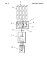
- the construction concept according to the invention is in the FIG. 1 outlined.
- the photovoltaic system consists of several module strands 2 whose connecting leads are led to a generator connection box 5.
- a plurality of DC-DC converter 3 are arranged, wherein each DC or DC converter 3, one or at most two module strands 2 are connected.
- the output voltages of all DC-DC converters 3 are combined and fed via a generator main connection line 6 to a central inverter 4, which in turn is connected to an AC switchgear cabinet 12, which is provided in particular for feeding the electrical energy supplied by the photovoltaic generator into a distribution network.
- Part of the AC voltage cabinet 12 is therefore at least one feed-in counter 14 symbolically represented here.
- the central inverter 4 and the AC switchgear cabinet 12 may also form a structural unit with each other.
- an electronic not shown here as an individual part Integrated control unit for the photovoltaic system, which preferably operates using a microprocessor.
- the generator junction box 5 is arranged spatially separated from the central inverter 4 and preferably placed in the most favorable possible spatial position to the entirety of the module strands 2.
- the cabling effort can be optimized as a whole, since on the one hand the total length of the connecting lines of the module strands 2 can be kept as small as possible and on the other hand, the wiring between the generator junction box 5 and the central inverter 4 may be limited to the generator main connection line 6 and a communication line 13, wherein the communication line 13 is in communication with a control device 16 within the generator junction box 5.
- each module strand 2 connected to each DC-DC converter 3 so also the stranded diodes can be omitted, whereby an improved efficiency is achieved.
- the in the FIG. 1 sketched photovoltaic system has only a single generator junction box 5.
- the photovoltaic system can also be realized with a plurality of spatially separated generator junction boxes.
- the MPP is regulated individually by the DC-DC converter 3 for each module string 2.
- the photovoltaic system achieves a particularly high yield for partial shading or parameter scattering.
- the MPP range can be increased to such an extent that even with partial shading the right MPP can be approached.
- the photovoltaic generator configuration thereby becomes much more flexible.
- not all module strings need to have the same length and technology.
- the measurement of the phase currents by means of a current monitoring by the control device 16 can be used for MPP control. This avoids double current measurement, which helps to reduce costs.
- the measurement of the phase currents can be supplemented advantageously by monitoring the phase voltages. For a much better diagnosis of the module strands 2 is possible, whereby the yield can be secured.
- the voltage in the generator main connection line 6 can be increased by the DC voltage converter 3 integrated in the generator connection box 5, as a result of which the current drops correspondingly. This means either less losses or it can be chosen a smaller cable cross-section. Since the voltage here is always above the mains voltage, the necessary cable cross-section is in any case smaller than with the AC coupling in a module string inverter concept.
- the components of the central inverter 4 can be optimized in terms of the expected power loss, whereby the cost can be reduced and the efficiency can be increased.
- the wiring is easier than in a module string or multi-module string inverter 4a, as from a comparison with the FIG. 3 is easily apparent. Only one backup set 15 is needed.
- DC-DC converters 3 are designed as galvanically separating DC-DC converters.
- all module technologies can be connected to generator junction box 5 and earthed as required.
- the current can be reliably prevented by a signal from the inverter or a control center.
- the generator main connection line 6 is no longer supplied with energy.
- the central inverter 4 is disconnected from the medium-voltage network, the central inverter 4 and the generator main connection line 6 is safely switched off from all voltage sources.
- An additional DC voltage disconnect can be omitted hereby.
- not only the central inverter 4 is released, but also the DC voltage leading generator main connection line. 6
- module strands 2 can be switched off without switching off the entire photovoltaic system. This reduces yield loss during maintenance work on individual modules 2.
Landscapes
- Engineering & Computer Science (AREA)
- Power Engineering (AREA)
- Supply And Distribution Of Alternating Current (AREA)
- Inverter Devices (AREA)
- Photovoltaic Devices (AREA)
Applications Claiming Priority (1)
| Application Number | Priority Date | Filing Date | Title |
|---|---|---|---|
| DE102009032288A DE102009032288A1 (de) | 2009-07-09 | 2009-07-09 | Photovoltaikanlage |
Publications (3)
| Publication Number | Publication Date |
|---|---|
| EP2276137A2 true EP2276137A2 (fr) | 2011-01-19 |
| EP2276137A3 EP2276137A3 (fr) | 2014-03-05 |
| EP2276137B1 EP2276137B1 (fr) | 2018-11-07 |
Family
ID=43301939
Family Applications (1)
| Application Number | Title | Priority Date | Filing Date |
|---|---|---|---|
| EP10168764.8A Not-in-force EP2276137B1 (fr) | 2009-07-09 | 2010-07-07 | Installation photovoltaïque |
Country Status (3)
| Country | Link |
|---|---|
| US (1) | US8344549B2 (fr) |
| EP (1) | EP2276137B1 (fr) |
| DE (1) | DE102009032288A1 (fr) |
Cited By (5)
| Publication number | Priority date | Publication date | Assignee | Title |
|---|---|---|---|---|
| EP2625762A4 (fr) * | 2010-10-05 | 2015-05-20 | Alencon Acquisition Co Llc | Systèmes de courant électrique à collecte d'énergie à haute tension et conversion d'énergie renouvelable à taille de réseau public de distribution d'électricité et systèmes de surveillance visuelle et de commande pour lesdits systèmes |
| EP2707933A4 (fr) * | 2011-05-12 | 2015-05-20 | Alencon Acquisition Co Llc | Systèmes d'alimentation électrique de récolte d'énergie à haute tension et d'énergie renouvelable de conversion de la taille d'une installation et systèmes de surveillance et de contrôle visuels |
| WO2015110400A1 (fr) * | 2014-01-22 | 2015-07-30 | Sma Solar Technology Ag | Onduleur notamment en tant que partie d'un dispositif mixte de génération d'énergie et procédé |
| US9350166B2 (en) | 2010-10-05 | 2016-05-24 | Alencon Acquisition Co., Llc | High voltage energy harvesting and conversion renewable energy utility size electric power systems and visual monitoring and control systems for said systems |
| US10483759B2 (en) | 2016-04-07 | 2019-11-19 | Alencon Acquisition Co., Llc | Integrated multi-mode large-scale electric power support system for an electrical grid |
Families Citing this family (17)
| Publication number | Priority date | Publication date | Assignee | Title |
|---|---|---|---|---|
| ATE555531T1 (de) * | 2009-08-06 | 2012-05-15 | Sma Solar Technology Ag | Rückstromsensor für parallel geschaltete solarmodule |
| DE102010017747A1 (de) * | 2010-05-03 | 2011-11-03 | Sma Solar Technology Ag | Verfahren zur Begrenzung der Generatorspannung einer photovoltaischen Anlage im Gefahrenfall und photovoltaische Anlage |
| US8525369B2 (en) * | 2010-06-02 | 2013-09-03 | GM Global Technology Operations LLC | Method and device for optimizing the use of solar electrical power |
| WO2012046331A1 (fr) * | 2010-10-07 | 2012-04-12 | 東芝三菱電機産業システム株式会社 | Appareil de détection de défauts |
| US20120263252A1 (en) * | 2011-04-12 | 2012-10-18 | Texas Instruments Incorporated | Systems and Methods of Power Line Transmission of Solar Panel Data |
| ITVI20110117A1 (it) * | 2011-05-04 | 2012-11-05 | Itaco S R L | Impianto fotovoltaico |
| US9459139B2 (en) * | 2011-09-06 | 2016-10-04 | Morgan Solar Inc. | Photovoltaic generating system with control unit for controlling output power conversion and actuation of photovoltaic tracker units |
| US10115841B2 (en) * | 2012-06-04 | 2018-10-30 | Solaredge Technologies Ltd. | Integrated photovoltaic panel circuitry |
| DE102012214463A1 (de) * | 2012-08-14 | 2014-02-20 | Tim Meyer | Vorrichtung und Verfahren zur Stromeinspeisung aus einer oder mehreren Stromerzeugungs-oder Speicheranlagen in zwei oder mehr Einspeisungspunkte |
| DE102012112184A1 (de) | 2012-12-12 | 2014-06-12 | Sma Solar Technology Ag | Verfahren und Vorrichtung zum Schutz mehrerer Strings eines Photovoltaikgenerators vor Rückströmen |
| DE102012113016B4 (de) | 2012-12-21 | 2015-02-12 | Sma Solar Technology Ag | Netzersatzanlage und Verfahren zum Trennen eines lokalen Energieverteilungsnetzes von einem übergeordneten Energieversorgungsnetz |
| EP2951903B1 (fr) | 2013-01-30 | 2018-03-14 | SMA Solar Technology AG | Procédé et onduleur pour distribuer la puissance par l'intermédiaire de plusieurs sources de courant continu connectées collectivement à une entrée de tension continue d'un convertisseur cc/ca |
| GB2524224A (en) * | 2014-01-14 | 2015-09-23 | Dennis Majoe | Heart activity and blood flow measuring device |
| JP6261367B2 (ja) * | 2014-02-17 | 2018-01-17 | 田淵電機株式会社 | 太陽光発電システムにおける電力変換装置、ならびにこれに含まれる接続箱およびパワーコンディショナ |
| WO2019205289A1 (fr) * | 2018-04-28 | 2019-10-31 | 北京汉能光伏投资有限公司 | Boîte de jonction de composant solaire, système solaire et procédé de commande de composant solaire |
| KR102520478B1 (ko) | 2020-09-18 | 2023-04-10 | 한화솔루션 주식회사 | 태양광 발전 시스템, 및 이의 모니터링 장치와 방법 |
| WO2022227083A1 (fr) * | 2021-04-30 | 2022-11-03 | 华为数字能源技术有限公司 | Boîtier de convertisseur de puissance et système photovoltaïque |
Citations (2)
| Publication number | Priority date | Publication date | Assignee | Title |
|---|---|---|---|---|
| DE19919766A1 (de) | 1999-04-29 | 2000-11-02 | Sma Regelsysteme Gmbh | Wechselrichter für eine Photovoltaik-Anlage |
| DE10136147B4 (de) | 2001-07-25 | 2004-11-04 | Kolm, Hendrik, Dipl.-Ing. | Photovoltaischer Wechselstromerzeuger |
Family Cites Families (6)
| Publication number | Priority date | Publication date | Assignee | Title |
|---|---|---|---|---|
| JP2000112545A (ja) * | 1998-09-30 | 2000-04-21 | Daihen Corp | 太陽光発電システム |
| EP2012363A1 (fr) * | 2006-04-24 | 2009-01-07 | Sharp Kabushiki Kaisha | Systeme de generation d'energie photovoltaique et procede de commande de systeme de generation d'energie photovoltaique |
| DE102006023563B4 (de) * | 2006-05-19 | 2020-09-10 | Kostal Industrie Elektrik Gmbh | Photovoltaik-Anlage |
| JP5124114B2 (ja) * | 2006-08-28 | 2013-01-23 | シャープ株式会社 | 蓄電機能を有するパワーコンディショナ |
| DE102006062412A1 (de) * | 2006-12-21 | 2008-06-26 | Franz Blender | DC-Spannungsanpasser |
| EP2693289A4 (fr) * | 2011-03-30 | 2015-03-18 | Sanyo Electric Co | Boîte de captage de courant |
-
2009
- 2009-07-09 DE DE102009032288A patent/DE102009032288A1/de not_active Withdrawn
-
2010
- 2010-05-27 US US12/788,441 patent/US8344549B2/en not_active Expired - Fee Related
- 2010-07-07 EP EP10168764.8A patent/EP2276137B1/fr not_active Not-in-force
Patent Citations (2)
| Publication number | Priority date | Publication date | Assignee | Title |
|---|---|---|---|---|
| DE19919766A1 (de) | 1999-04-29 | 2000-11-02 | Sma Regelsysteme Gmbh | Wechselrichter für eine Photovoltaik-Anlage |
| DE10136147B4 (de) | 2001-07-25 | 2004-11-04 | Kolm, Hendrik, Dipl.-Ing. | Photovoltaischer Wechselstromerzeuger |
Cited By (7)
| Publication number | Priority date | Publication date | Assignee | Title |
|---|---|---|---|---|
| EP2625762A4 (fr) * | 2010-10-05 | 2015-05-20 | Alencon Acquisition Co Llc | Systèmes de courant électrique à collecte d'énergie à haute tension et conversion d'énergie renouvelable à taille de réseau public de distribution d'électricité et systèmes de surveillance visuelle et de commande pour lesdits systèmes |
| US9350166B2 (en) | 2010-10-05 | 2016-05-24 | Alencon Acquisition Co., Llc | High voltage energy harvesting and conversion renewable energy utility size electric power systems and visual monitoring and control systems for said systems |
| EP2707933A4 (fr) * | 2011-05-12 | 2015-05-20 | Alencon Acquisition Co Llc | Systèmes d'alimentation électrique de récolte d'énergie à haute tension et d'énergie renouvelable de conversion de la taille d'une installation et systèmes de surveillance et de contrôle visuels |
| AU2012253314B2 (en) * | 2011-05-12 | 2016-11-24 | Alencon Acquisition Co., Llc | High voltage energy harvesting and conversion renewable energy utility size electric power systems and visual monitoring and control systems |
| US9627889B2 (en) | 2011-05-12 | 2017-04-18 | Alencon Acquisition Co., Llc. | High voltage energy harvesting and conversion renewable energy utility size electric power systems and visual monitoring and control systems |
| WO2015110400A1 (fr) * | 2014-01-22 | 2015-07-30 | Sma Solar Technology Ag | Onduleur notamment en tant que partie d'un dispositif mixte de génération d'énergie et procédé |
| US10483759B2 (en) | 2016-04-07 | 2019-11-19 | Alencon Acquisition Co., Llc | Integrated multi-mode large-scale electric power support system for an electrical grid |
Also Published As
| Publication number | Publication date |
|---|---|
| US8344549B2 (en) | 2013-01-01 |
| EP2276137B1 (fr) | 2018-11-07 |
| EP2276137A3 (fr) | 2014-03-05 |
| DE102009032288A1 (de) | 2011-01-13 |
| US20110006609A1 (en) | 2011-01-13 |
Similar Documents
| Publication | Publication Date | Title |
|---|---|---|
| EP2276137B1 (fr) | Installation photovoltaïque | |
| EP1841050B1 (fr) | Procédé pour convertir une tension continue en une tension triphasée | |
| EP2296244B1 (fr) | Procédé et dispositif destinés à la connexion d'au moins une chaîne d'installation photovoltaïque et d'un onduleur | |
| EP2284973B1 (fr) | Capteur de flux de retour pour de modules solaire branché en parallèle | |
| DE102012023424B4 (de) | Energieverteilungsanlage mit einer Steuervorrichtung | |
| EP2282388A1 (fr) | Dispositif d'alimentation en énergie électrique d'une multitude de chaînes de modules photovoltaïques dans un réseau électrique | |
| DE102011110682A1 (de) | Anschlussdose für ein Solarpanel mit einer Schutzschaltung | |
| DE102008008504A1 (de) | Verfahren zur Diebstahlerkennung eines PV-Moduls und zur Ausfallerkennung einer Bypassdiode eines PV-Moduls sowie dazu korrespondierender PV-Teilgenerator-Anschlusskasten, PV-Wechselrichter und dazu korrespondierende PV-Anlage | |
| DE102016117049A1 (de) | Multistrang-Photovoltaik-Anlage, Verfahren zum Betrieb einer solchen und Rückstromschutzschaltung für eine solche | |
| EP0297079B1 (fr) | Dispositif de contrôle et de surveillance d'un système de distribution d'énergie électrique | |
| DE102017011374A1 (de) | Schutzeinrichtung für Niederspannungsanlagen mit integrierter Messelektronik | |
| WO2020099055A1 (fr) | Installation de transformation d'un réseau de distribution électrique ainsi que procédé de fonctionnement d'une installation de transformation | |
| EP2478420B1 (fr) | Circuit doté d'une partie onduleur comprenant une unité de commande centrale | |
| DE102010037760B4 (de) | Vorrichtung und Verfahren zur Spannungsfreischaltung elektrischer, in einem Gebäude oder Gebäudekomplex verlaufender Leitungen einer Photovoltaikanlage, Verwendung der Vorrichtung sowie System mit der Vorrichtung und einer Photovoltaikanlage | |
| DE102017011373A1 (de) | Mess- und Steuerelektronik für Niederspannungsschaltanlagen | |
| DE102010037995B4 (de) | Stromversorgungsgerät und Stromversorgungssystem mit ebensolchem | |
| EP2555003A2 (fr) | Transducteur de courant et sectionneur de charge étant équipé avec celui-ci | |
| WO2014154233A1 (fr) | Boîte de jonction pour le raccordement électrique d'une pluralité de générateurs photovoltaïques et installation de production d'énergie photovoltaïque | |
| EP2874265A1 (fr) | Procédé et système de surveillance et de commande d'une distribution de courant dans un réseau de distribution d'énergie | |
| EP3763176B1 (fr) | Ensemble convertisseur enfichable de conception modulaire et système d'alimentation en courant de commande de processus pour une centrale nucléaire | |
| CH697400B1 (de) | Vorrichtung zum Anschliessen einer elektrischen Last an eine Energiequelle. | |
| EP2498300A1 (fr) | Installation photovoltaïque, dispositif de commande et dispositif de commutation | |
| DE202024101179U1 (de) | Gleichstrom-Photovoltaik-Einspeisesystem | |
| DE102019202921B4 (de) | Lichtverteilervorrichtung für eine Fertigungsinfrastruktur, Verfahren zum Bestücken einer Lichtverteilervorrichtung | |
| DE102013112362A1 (de) | Photovoltaikanlage sowie Betriebsverfahren und Wechselrichter für eine Photovoltaikanlage |
Legal Events
| Date | Code | Title | Description |
|---|---|---|---|
| PUAI | Public reference made under article 153(3) epc to a published international application that has entered the european phase |
Free format text: ORIGINAL CODE: 0009012 |
|
| AK | Designated contracting states |
Kind code of ref document: A2 Designated state(s): AL AT BE BG CH CY CZ DE DK EE ES FI FR GB GR HR HU IE IS IT LI LT LU LV MC MK MT NL NO PL PT RO SE SI SK SM TR |
|
| AX | Request for extension of the european patent |
Extension state: BA ME RS |
|
| REG | Reference to a national code |
Ref country code: DE Ref legal event code: R079 Ref document number: 502010015530 Country of ref document: DE Free format text: PREVIOUS MAIN CLASS: H02J0003380000 Ipc: H01L0031020000 |
|
| PUAL | Search report despatched |
Free format text: ORIGINAL CODE: 0009013 |
|
| AK | Designated contracting states |
Kind code of ref document: A3 Designated state(s): AL AT BE BG CH CY CZ DE DK EE ES FI FR GB GR HR HU IE IS IT LI LT LU LV MC MK MT NL NO PL PT RO SE SI SK SM TR |
|
| AX | Request for extension of the european patent |
Extension state: BA ME RS |
|
| RIC1 | Information provided on ipc code assigned before grant |
Ipc: H01L 31/02 20060101AFI20140127BHEP |
|
| 17P | Request for examination filed |
Effective date: 20140415 |
|
| RBV | Designated contracting states (corrected) |
Designated state(s): AL AT BE BG CH CY CZ DE DK EE ES FI FR GB GR HR HU IE IS IT LI LT LU LV MC MK MT NL NO PL PT RO SE SI SK SM TR |
|
| 17Q | First examination report despatched |
Effective date: 20141023 |
|
| STAA | Information on the status of an ep patent application or granted ep patent |
Free format text: STATUS: EXAMINATION IS IN PROGRESS |
|
| GRAP | Despatch of communication of intention to grant a patent |
Free format text: ORIGINAL CODE: EPIDOSNIGR1 |
|
| STAA | Information on the status of an ep patent application or granted ep patent |
Free format text: STATUS: GRANT OF PATENT IS INTENDED |
|
| INTG | Intention to grant announced |
Effective date: 20180531 |
|
| GRAJ | Information related to disapproval of communication of intention to grant by the applicant or resumption of examination proceedings by the epo deleted |
Free format text: ORIGINAL CODE: EPIDOSDIGR1 |
|
| STAA | Information on the status of an ep patent application or granted ep patent |
Free format text: STATUS: EXAMINATION IS IN PROGRESS |
|
| GRAP | Despatch of communication of intention to grant a patent |
Free format text: ORIGINAL CODE: EPIDOSNIGR1 |
|
| STAA | Information on the status of an ep patent application or granted ep patent |
Free format text: STATUS: GRANT OF PATENT IS INTENDED |
|
| INTC | Intention to grant announced (deleted) | ||
| GRAS | Grant fee paid |
Free format text: ORIGINAL CODE: EPIDOSNIGR3 |
|
| INTG | Intention to grant announced |
Effective date: 20180906 |
|
| GRAA | (expected) grant |
Free format text: ORIGINAL CODE: 0009210 |
|
| STAA | Information on the status of an ep patent application or granted ep patent |
Free format text: STATUS: THE PATENT HAS BEEN GRANTED |
|
| AK | Designated contracting states |
Kind code of ref document: B1 Designated state(s): AL AT BE BG CH CY CZ DE DK EE ES FI FR GB GR HR HU IE IS IT LI LT LU LV MC MK MT NL NO PL PT RO SE SI SK SM TR |
|
| REG | Reference to a national code |
Ref country code: GB Ref legal event code: FG4D Free format text: NOT ENGLISH |
|
| REG | Reference to a national code |
Ref country code: CH Ref legal event code: EP Ref country code: AT Ref legal event code: REF Ref document number: 1063110 Country of ref document: AT Kind code of ref document: T Effective date: 20181115 |
|
| REG | Reference to a national code |
Ref country code: IE Ref legal event code: FG4D Free format text: LANGUAGE OF EP DOCUMENT: GERMAN |
|
| REG | Reference to a national code |
Ref country code: DE Ref legal event code: R096 Ref document number: 502010015530 Country of ref document: DE |
|
| REG | Reference to a national code |
Ref country code: NL Ref legal event code: MP Effective date: 20181107 |
|
| REG | Reference to a national code |
Ref country code: LT Ref legal event code: MG4D |
|
| PG25 | Lapsed in a contracting state [announced via postgrant information from national office to epo] |
Ref country code: ES Free format text: LAPSE BECAUSE OF FAILURE TO SUBMIT A TRANSLATION OF THE DESCRIPTION OR TO PAY THE FEE WITHIN THE PRESCRIBED TIME-LIMIT Effective date: 20181107 Ref country code: LV Free format text: LAPSE BECAUSE OF FAILURE TO SUBMIT A TRANSLATION OF THE DESCRIPTION OR TO PAY THE FEE WITHIN THE PRESCRIBED TIME-LIMIT Effective date: 20181107 Ref country code: HR Free format text: LAPSE BECAUSE OF FAILURE TO SUBMIT A TRANSLATION OF THE DESCRIPTION OR TO PAY THE FEE WITHIN THE PRESCRIBED TIME-LIMIT Effective date: 20181107 Ref country code: BG Free format text: LAPSE BECAUSE OF FAILURE TO SUBMIT A TRANSLATION OF THE DESCRIPTION OR TO PAY THE FEE WITHIN THE PRESCRIBED TIME-LIMIT Effective date: 20190207 Ref country code: LT Free format text: LAPSE BECAUSE OF FAILURE TO SUBMIT A TRANSLATION OF THE DESCRIPTION OR TO PAY THE FEE WITHIN THE PRESCRIBED TIME-LIMIT Effective date: 20181107 Ref country code: FI Free format text: LAPSE BECAUSE OF FAILURE TO SUBMIT A TRANSLATION OF THE DESCRIPTION OR TO PAY THE FEE WITHIN THE PRESCRIBED TIME-LIMIT Effective date: 20181107 Ref country code: IS Free format text: LAPSE BECAUSE OF FAILURE TO SUBMIT A TRANSLATION OF THE DESCRIPTION OR TO PAY THE FEE WITHIN THE PRESCRIBED TIME-LIMIT Effective date: 20190307 Ref country code: NO Free format text: LAPSE BECAUSE OF FAILURE TO SUBMIT A TRANSLATION OF THE DESCRIPTION OR TO PAY THE FEE WITHIN THE PRESCRIBED TIME-LIMIT Effective date: 20190207 |
|
| PG25 | Lapsed in a contracting state [announced via postgrant information from national office to epo] |
Ref country code: NL Free format text: LAPSE BECAUSE OF FAILURE TO SUBMIT A TRANSLATION OF THE DESCRIPTION OR TO PAY THE FEE WITHIN THE PRESCRIBED TIME-LIMIT Effective date: 20181107 Ref country code: SE Free format text: LAPSE BECAUSE OF FAILURE TO SUBMIT A TRANSLATION OF THE DESCRIPTION OR TO PAY THE FEE WITHIN THE PRESCRIBED TIME-LIMIT Effective date: 20181107 Ref country code: GR Free format text: LAPSE BECAUSE OF FAILURE TO SUBMIT A TRANSLATION OF THE DESCRIPTION OR TO PAY THE FEE WITHIN THE PRESCRIBED TIME-LIMIT Effective date: 20190208 Ref country code: AL Free format text: LAPSE BECAUSE OF FAILURE TO SUBMIT A TRANSLATION OF THE DESCRIPTION OR TO PAY THE FEE WITHIN THE PRESCRIBED TIME-LIMIT Effective date: 20181107 Ref country code: PT Free format text: LAPSE BECAUSE OF FAILURE TO SUBMIT A TRANSLATION OF THE DESCRIPTION OR TO PAY THE FEE WITHIN THE PRESCRIBED TIME-LIMIT Effective date: 20190307 |
|
| PG25 | Lapsed in a contracting state [announced via postgrant information from national office to epo] |
Ref country code: DK Free format text: LAPSE BECAUSE OF FAILURE TO SUBMIT A TRANSLATION OF THE DESCRIPTION OR TO PAY THE FEE WITHIN THE PRESCRIBED TIME-LIMIT Effective date: 20181107 Ref country code: IT Free format text: LAPSE BECAUSE OF FAILURE TO SUBMIT A TRANSLATION OF THE DESCRIPTION OR TO PAY THE FEE WITHIN THE PRESCRIBED TIME-LIMIT Effective date: 20181107 Ref country code: PL Free format text: LAPSE BECAUSE OF FAILURE TO SUBMIT A TRANSLATION OF THE DESCRIPTION OR TO PAY THE FEE WITHIN THE PRESCRIBED TIME-LIMIT Effective date: 20181107 Ref country code: CZ Free format text: LAPSE BECAUSE OF FAILURE TO SUBMIT A TRANSLATION OF THE DESCRIPTION OR TO PAY THE FEE WITHIN THE PRESCRIBED TIME-LIMIT Effective date: 20181107 |
|
| REG | Reference to a national code |
Ref country code: DE Ref legal event code: R097 Ref document number: 502010015530 Country of ref document: DE |
|
| PG25 | Lapsed in a contracting state [announced via postgrant information from national office to epo] |
Ref country code: RO Free format text: LAPSE BECAUSE OF FAILURE TO SUBMIT A TRANSLATION OF THE DESCRIPTION OR TO PAY THE FEE WITHIN THE PRESCRIBED TIME-LIMIT Effective date: 20181107 Ref country code: SK Free format text: LAPSE BECAUSE OF FAILURE TO SUBMIT A TRANSLATION OF THE DESCRIPTION OR TO PAY THE FEE WITHIN THE PRESCRIBED TIME-LIMIT Effective date: 20181107 Ref country code: SM Free format text: LAPSE BECAUSE OF FAILURE TO SUBMIT A TRANSLATION OF THE DESCRIPTION OR TO PAY THE FEE WITHIN THE PRESCRIBED TIME-LIMIT Effective date: 20181107 Ref country code: EE Free format text: LAPSE BECAUSE OF FAILURE TO SUBMIT A TRANSLATION OF THE DESCRIPTION OR TO PAY THE FEE WITHIN THE PRESCRIBED TIME-LIMIT Effective date: 20181107 |
|
| PLBE | No opposition filed within time limit |
Free format text: ORIGINAL CODE: 0009261 |
|
| STAA | Information on the status of an ep patent application or granted ep patent |
Free format text: STATUS: NO OPPOSITION FILED WITHIN TIME LIMIT |
|
| 26N | No opposition filed |
Effective date: 20190808 |
|
| PG25 | Lapsed in a contracting state [announced via postgrant information from national office to epo] |
Ref country code: SI Free format text: LAPSE BECAUSE OF FAILURE TO SUBMIT A TRANSLATION OF THE DESCRIPTION OR TO PAY THE FEE WITHIN THE PRESCRIBED TIME-LIMIT Effective date: 20181107 |
|
| PG25 | Lapsed in a contracting state [announced via postgrant information from national office to epo] |
Ref country code: MC Free format text: LAPSE BECAUSE OF FAILURE TO SUBMIT A TRANSLATION OF THE DESCRIPTION OR TO PAY THE FEE WITHIN THE PRESCRIBED TIME-LIMIT Effective date: 20181107 |
|
| REG | Reference to a national code |
Ref country code: CH Ref legal event code: PL |
|
| PG25 | Lapsed in a contracting state [announced via postgrant information from national office to epo] |
Ref country code: TR Free format text: LAPSE BECAUSE OF FAILURE TO SUBMIT A TRANSLATION OF THE DESCRIPTION OR TO PAY THE FEE WITHIN THE PRESCRIBED TIME-LIMIT Effective date: 20181107 |
|
| REG | Reference to a national code |
Ref country code: BE Ref legal event code: MM Effective date: 20190731 |
|
| PG25 | Lapsed in a contracting state [announced via postgrant information from national office to epo] |
Ref country code: LI Free format text: LAPSE BECAUSE OF NON-PAYMENT OF DUE FEES Effective date: 20190731 Ref country code: CH Free format text: LAPSE BECAUSE OF NON-PAYMENT OF DUE FEES Effective date: 20190731 Ref country code: LU Free format text: LAPSE BECAUSE OF NON-PAYMENT OF DUE FEES Effective date: 20190707 Ref country code: BE Free format text: LAPSE BECAUSE OF NON-PAYMENT OF DUE FEES Effective date: 20190731 |
|
| PG25 | Lapsed in a contracting state [announced via postgrant information from national office to epo] |
Ref country code: IE Free format text: LAPSE BECAUSE OF NON-PAYMENT OF DUE FEES Effective date: 20190707 |
|
| REG | Reference to a national code |
Ref country code: AT Ref legal event code: MM01 Ref document number: 1063110 Country of ref document: AT Kind code of ref document: T Effective date: 20190707 |
|
| PG25 | Lapsed in a contracting state [announced via postgrant information from national office to epo] |
Ref country code: AT Free format text: LAPSE BECAUSE OF NON-PAYMENT OF DUE FEES Effective date: 20190707 |
|
| PG25 | Lapsed in a contracting state [announced via postgrant information from national office to epo] |
Ref country code: CY Free format text: LAPSE BECAUSE OF FAILURE TO SUBMIT A TRANSLATION OF THE DESCRIPTION OR TO PAY THE FEE WITHIN THE PRESCRIBED TIME-LIMIT Effective date: 20181107 |
|
| PG25 | Lapsed in a contracting state [announced via postgrant information from national office to epo] |
Ref country code: HU Free format text: LAPSE BECAUSE OF FAILURE TO SUBMIT A TRANSLATION OF THE DESCRIPTION OR TO PAY THE FEE WITHIN THE PRESCRIBED TIME-LIMIT; INVALID AB INITIO Effective date: 20100707 Ref country code: MT Free format text: LAPSE BECAUSE OF FAILURE TO SUBMIT A TRANSLATION OF THE DESCRIPTION OR TO PAY THE FEE WITHIN THE PRESCRIBED TIME-LIMIT Effective date: 20181107 |
|
| PG25 | Lapsed in a contracting state [announced via postgrant information from national office to epo] |
Ref country code: MK Free format text: LAPSE BECAUSE OF FAILURE TO SUBMIT A TRANSLATION OF THE DESCRIPTION OR TO PAY THE FEE WITHIN THE PRESCRIBED TIME-LIMIT Effective date: 20181107 |
|
| PGFP | Annual fee paid to national office [announced via postgrant information from national office to epo] |
Ref country code: GB Payment date: 20230822 Year of fee payment: 14 |
|
| PGFP | Annual fee paid to national office [announced via postgrant information from national office to epo] |
Ref country code: FR Payment date: 20230717 Year of fee payment: 14 |
|
| REG | Reference to a national code |
Ref country code: DE Ref legal event code: R081 Ref document number: 502010015530 Country of ref document: DE Owner name: KOSTAL INDUSTRIE ELEKTRIK GMBH & CO. KG, DE Free format text: FORMER OWNER: KOSTAL INDUSTRIE ELEKTRIK GMBH, 58513 LUEDENSCHEID, DE |
|
| PGFP | Annual fee paid to national office [announced via postgrant information from national office to epo] |
Ref country code: DE Payment date: 20240611 Year of fee payment: 15 |
|
| REG | Reference to a national code |
Ref country code: DE Ref legal event code: R079 Ref document number: 502010015530 Country of ref document: DE Free format text: PREVIOUS MAIN CLASS: H01L0031020000 Ipc: H10F0077000000 |
|
| GBPC | Gb: european patent ceased through non-payment of renewal fee |
Effective date: 20240707 |
|
| PG25 | Lapsed in a contracting state [announced via postgrant information from national office to epo] |
Ref country code: FR Free format text: LAPSE BECAUSE OF NON-PAYMENT OF DUE FEES Effective date: 20240731 |
|
| PG25 | Lapsed in a contracting state [announced via postgrant information from national office to epo] |
Ref country code: GB Free format text: LAPSE BECAUSE OF NON-PAYMENT OF DUE FEES Effective date: 20240707 |
|
| REG | Reference to a national code |
Ref country code: DE Ref legal event code: R119 Ref document number: 502010015530 Country of ref document: DE |
|
| PG25 | Lapsed in a contracting state [announced via postgrant information from national office to epo] |
Ref country code: DE Free format text: LAPSE BECAUSE OF NON-PAYMENT OF DUE FEES Effective date: 20260203 |