EP2276590B1 - Dispositif et procédé de pliage - Google Patents
Dispositif et procédé de pliage Download PDFInfo
- Publication number
- EP2276590B1 EP2276590B1 EP09721655A EP09721655A EP2276590B1 EP 2276590 B1 EP2276590 B1 EP 2276590B1 EP 09721655 A EP09721655 A EP 09721655A EP 09721655 A EP09721655 A EP 09721655A EP 2276590 B1 EP2276590 B1 EP 2276590B1
- Authority
- EP
- European Patent Office
- Prior art keywords
- hemming
- folding
- workpiece
- brace
- tool
- Prior art date
- Legal status (The legal status is an assumption and is not a legal conclusion. Google has not performed a legal analysis and makes no representation as to the accuracy of the status listed.)
- Active
Links
Images


Classifications
-
- B—PERFORMING OPERATIONS; TRANSPORTING
- B21—MECHANICAL METAL-WORKING WITHOUT ESSENTIALLY REMOVING MATERIAL; PUNCHING METAL
- B21D—WORKING OR PROCESSING OF SHEET METAL OR METAL TUBES, RODS OR PROFILES WITHOUT ESSENTIALLY REMOVING MATERIAL; PUNCHING METAL
- B21D39/00—Application of procedures in order to connect objects or parts, e.g. coating with sheet metal otherwise than by plating; Tube expanders
- B21D39/02—Application of procedures in order to connect objects or parts, e.g. coating with sheet metal otherwise than by plating; Tube expanders of sheet metal by folding, e.g. connecting edges of a sheet to form a cylinder
- B21D39/021—Application of procedures in order to connect objects or parts, e.g. coating with sheet metal otherwise than by plating; Tube expanders of sheet metal by folding, e.g. connecting edges of a sheet to form a cylinder for panels, e.g. vehicle doors
-
- B—PERFORMING OPERATIONS; TRANSPORTING
- B21—MECHANICAL METAL-WORKING WITHOUT ESSENTIALLY REMOVING MATERIAL; PUNCHING METAL
- B21D—WORKING OR PROCESSING OF SHEET METAL OR METAL TUBES, RODS OR PROFILES WITHOUT ESSENTIALLY REMOVING MATERIAL; PUNCHING METAL
- B21D19/00—Flanging or other edge treatment, e.g. of tubes
- B21D19/02—Flanging or other edge treatment, e.g. of tubes by continuously-acting tools moving along the edge
- B21D19/04—Flanging or other edge treatment, e.g. of tubes by continuously-acting tools moving along the edge shaped as rollers
- B21D19/043—Flanging or other edge treatment, e.g. of tubes by continuously-acting tools moving along the edge shaped as rollers for flanging edges of plates
-
- B—PERFORMING OPERATIONS; TRANSPORTING
- B25—HAND TOOLS; PORTABLE POWER-DRIVEN TOOLS; MANIPULATORS
- B25J—MANIPULATORS; CHAMBERS PROVIDED WITH MANIPULATION DEVICES
- B25J15/00—Gripping heads and other end effectors
- B25J15/0019—End effectors other than grippers
Definitions
- the invention relates to a folding device and a folding method having the features in the preamble of the device and method main claim 1 and 14 (see, for example, GB-A-2441709).
- the invention solves this problem with the features in the device and Maschinensmaschine products 1 and 14.
- the claimed folding device provides a high degree of flexibility and allows folding of workpieces even in previously problematic areas or positions.
- the bent seam edges or folding contours of wheel arches of vehicle bodies, in particular sidewalls can be folded in the assembled and joined position. Folding can be better integrated into the manufacturing process.
- On already assembled and joined sidewalls can also on the current and the joining possibly slightly changed position and shape of the workpiece area to be joined Be considered.
- the folding device with the folder guided by the manipulator preferably a Rollfalzwerkmaschine, and the anvil is highly flexible and can be adapted to any types and shapes of workpieces.
- the deliverable counterholder can have the function of a mobile folding bed and can be delivered to the workpiece area to be folded and positioned in a suitable position. The delivery can be done very gently by means of a flexible protective device, a so-called soft touch.
- the compliance of the protection device can be coupled with the delivery, which leads to a very high Zustell ceremonieszision.
- the counter-holder offers a folding bed in a defined position and can absorb the folding forces applied by the folding tool and support it to the outside. This allows a clean and accurate fold even with problematic folding contours. In addition, unwanted deformations or damage, in particular surface damage, of the workpiece are avoided by the abutment resting against the workpiece. Undefined areas of radius changes and undefined forces are also avoided. Instability factors for the folding process are switched off.
- the folding tool can be optimally adapted to the folding process and can be handled by the manipulator in the desired and optimal way. With the folding tool only the forces and movements required for bending the sheet metal edges or edge flanges need to be applied. A support of the folding and reaction forces within the folding tool by an example forceps-shaped design, is not required. The folding tool can thereby a slimmer in shape and provide greater kinematic freedom and greater agility.
- the external counter support Due to the external supportability of the counter-holder, the workpiece can be loaded less. In particular, no support of the folding forces on the workpiece itself by a local support of the counter-holder is required.
- the external counter support also offers advantages for the speed and reliability of the folding process.
- the feed movements can be carried out quickly and safely, which shortens the cycle time and also allows a quick change of the workpieces.
- the external Schmidtabst Reifenung also has the advantage that the folding forces can be supported in an optimal manner and secure stationary.
- the counter-holder can rest exactly and with a large surface on the workpiece area to be folded. Deformations on this contact area of the workpiece and also relative movements between the workpiece and the counterholder can be avoided in favor of optimum folding force support. Due to the external support, the counterholder does not give way in an undesired manner. Rather, it guarantees a safe and accurate folding process.
- an external support device with a multi-axis movable positioning device and a fixing device can be provided.
- the support device allows an accurate delivery of the equipped with a customized and possibly replaceable molding counter-holder to be folded to the workpiece area. In this case, any tolerances or position deviations of the workpiece area to be folded can be compensated.
- the delivery can be done by means of their own drives the support means or alternatively by the manipulator. With the fixing the mobility of the positioning are blocked in the found folding position and the Stiffening support stiffened for safe absorption of the folding forces.
- the manipulator can move the folding tool along the folding contour, thereby bending and folding the one or more sheet metal edges or edge flanges in one or more steps.
- the folding tool can be multifunctional for this purpose and have a plurality of rotatable and possibly spring-mounted folding rollers.
- An entrained roller drive improves the folding process. Due to the counter holder, the folding tool needs to be designed and optimized in the above-mentioned manner only on the folding process. It can thus build very slim and have a high functionality.
- the manipulator moves the folding tool along a preprogrammed and stored path.
- a detection device can be present, which can be designed and arranged in different ways.
- the detection of the position of the workpiece area to be folded or of the seam edge can be done on site by means of a stationary or by the manipulator entrained optical detection device.
- the position and possibly also the shape of the seaming edge or seaming contour can be determined and reported to the robot controller for a possible adaptation of the stored seaming sheet.
- Both variants have the advantage that the actual data of the folding contour are recorded at the processing location and are thus up-to-date. Any previous workpiece deformations during joining or the like can be included and taken into account.
- the position and possibly also the shape of the seaming edge or seaming contour can be picked up at an earlier point in time and elsewhere and transmitted to the manipulator control.
- the programmed path can be aligned and corrected if necessary, e.g. by a base shift.
- the claimed folding device and the associated folding method offer high flexibility and high process reliability and short cycle times.
- the folding processor can be optimally adapted to the workpiece conditions. Any workpiece deviations can be compensated.
- the folding tool can act particularly gently on the workpiece. The fold receives exactly the desired shape and position. At a high folding precision results in a particularly high efficiency of the folding technique.
- the folding device can also be used in conjunction with a magazine for several replaceable counter-holder and a multifunctional folding and transport tool for flexible production lines for processing various body types.
- the invention relates to a folding device (1) for workpieces (2) and a folding method.
- the invention relates to the robot folding.
- Folding is also referred to as flanging.
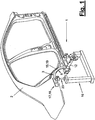
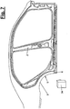
- the workpieces (2) can be of any type and size. In the preferred embodiment, it is body parts, in particular to side walls of body shells. Such a side wall consists of several sheet metal layers, such as an inner shell (7) and an outer shell (8) to be folded at the edge.
- the workpiece (2) has one or more workpiece areas to be folded (3). In the illustrated embodiment of a side wall (2) this is, for example, the rear wheel arch (3), which has a curved seam (5).
- FIG. 7 and 9 illustrate this education.
- FIGS. 10 and 11 show for this two design variants of the sheet metal layers (7,8), in which the inner and outer sheet edges or the so-called.
- Inner and outer flanges (9,10) are pre-folded in the starting position shown on the left side. During the folding process, the inner and outer flanges (9,10) in the right picture of FIGS. 10 and 11 shown end position are brought. In the variant of FIG. 10 the already double folded inner and outer flanges (9,10) are close to each other and are bent even further when folding.
- FIG. 10 shows the Flanschausgangslage in dashed form.
- the edge region of the wheel arch is understood, at which the in FIGS. 10 and 11
- flanges or sheet metal edges (9,10) are located.
- the lower bending edge of the workpiece area (3) in this case forms the externally visible seaming edge (5) or the folding contour on the wheel arch.
- the inner and outer flanges (9,10) are located on the inside of the wheel arch and are not visible from the outside. From the outside, however, you can see the in FIGS. 10 and 11 shown first obliquely inwardly bent flange, against which the free sheet edges or inner flanges (9,10) are folded and folded from the inside.
- This visible Radhausrand Scheme is critical by its oblique fold inwards and by its according to the folding contour (5) shape with respect to changes in shape.
- the inner and / or outer flange (9,10) can be folded so that it does not come to visually perceptible changes in shape or impairments in the surface quality at this visible Radhausrand Scheme.
- the workpiece (2) or the side wall in the vicinity of the workpiece area to be folded (3) one or more reference marks (6). These have a fixed and preset reference to the spatial position of the workpiece area (3) and the folded edge (5) and the flanges (9,10). If one detects the position of the one or more reference marks (6), the spatial position of the workpiece area (3) and the folded edge (5) as well as the flanges (9, 10) and possibly also their shape is thereby defined via the positional reference.
- the folding device (1) is preferably designed as a robot folding device. It has at least one multi-axially movable manipulator (13) with at least one entrained folding tool (12) and a counter-holder (15) which receives and supports the folding forces applied by the folding tool (12).
- the support (15) can be assigned a supporting device (15) that can be stationarily supported outside the workpiece (2).
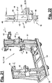
- FIGS. 13 to 22 show a first variant of the folding device (1) and its components in different views.
- the manipulator (13) is shown.
- the folding tool (12) is shown for the sake of clarity.
- FIG. 12 schematically shows the arrangement and kinematics or axis arrangement of the folding device (1).
- FIGS. 13 to 22 a second variant of the folding device (1) is shown.
- the manipulator (13) also has a controller (32).
- This manipulator or robot controller (32) can have a number of additional control axes, which are connected with the other components of the folding device (1) in a suitable manner, for example via the in FIG. 3 shown lines (33) may be connected.
- the entire folding device (1) can be controlled with all its movable components.
- the workpiece (2) in particular the side wall shown, can be positioned and held for folding in any suitable manner, in particular tensioned.
- the side wall (2) can already be fitted with other body parts, e.g. a floor group, roof bows, a stem or the like. Be joined.
- the folding can take place in particular within the production line and joint line of the vehicle body, for example in the shaping geometry or framing station or in the subsequent welding stations. Alternatively, these joining stations may be followed by a separate folding station or integrated elsewhere in the line. Furthermore, it is possible to perform the folding process also in the workpiece production, in particular the sidewall production and thus outside the joint lines.
- the side wall (2) is already joined and is folded after welding, wherein the vehicle body is fixed in a predetermined position by means of a suitable clamping device (not shown).
- the counter-holder (15) can be delivered to the workpiece area to be folded (3) and in particular to the aforementioned visible from the outside Radhausrand Scheme (3) and created with large-area contact. Delivery can be multi-level.
- the counterholder (15) takes the from the folding tool (12) on the inner flanges (9,10) applied folding forces and supports them externally and outside of the workpiece (2).
- the support device (16) can be stationarily supported outside the workpiece (2), for example at the station floor or at a component of the station frame.
- the anvil (15) may have the form and function of a mobile folding bed. The workpiece area (3) is thereby held in exact position during folding and firmly and securely supported.
- FIG. 11 and 12 show in a dashed line, if necessary, the design and arrangement of the counter-holder (15) on the workpiece area to be folded (3).
- the counter-holder (15) has at least one molded part (19), which is adapted in its shape to the workpiece area to be folded (3), in this case the outwardly directed Radhausrand Scheme.
- the molded part (19) can follow in its shape and extent the curved fold edge (5) and leaves it free for the access of the folding tool (12) in a suitable manner.
- the molded part (19) has on its inner side facing the workpiece area (3) to be folded a contour corresponding to this workpiece area (3) for a largely planar contact. The molded part (19) can thereby be delivered close and tight to the workpiece area (3) and nestled.
- the support device (16) has a multi-axially movable positioning device (17) and a fixing device (18). With the support means (16) of the counter-holder (15) can be delivered in the abutment position to be folded to the workpiece area (3) and fixed in this position, wherein the support means (16) is stiffened and can absorb the folding forces and support stationary on the ground ,
- the positioning device (17) can be designed in any suitable manner. It has drives with adjusting elements and mobility or degrees of freedom of the counter-holder (15) relative to the actuating elements, which enable position finding by orientation on the workpiece (2) or workpiece area (3).
- the adjusting elements carry at least in the end position the counter-holder (15) and absorb the process forces, in particular folding and pressing forces.
- the positioning device (17) consists in the first variant, e.g. from a plurality of multi-axially movable adjusting or supporting elements (23) which are fixedly or detachably connected to a holder (20, 21).
- the support elements (23) are arranged on a rigid frame (22) of the support means (16), which e.g. consists of a base and a plurality of columnar receptacles for the support elements (23) and is supported in a suitable manner on the ground, on the station rack or elsewhere in a stationary manner.
- the frame (22) can be rigidly attached to a substrate. It may alternatively have a movement axis and be locked for the folding process in the support position.
- the positioning device (17) allows the feed movement of the counter-holder (15) in the contact position for folding and a return stroke for the release and the removal and the change of the workpiece (2). It has several axes of motion for this purpose.
- the positioning device (17) offers the in FIG. 2 shown on a station coordinate system spatial and in particular six-axis mobility. These are on the one hand translational feed axes in the x-, y- and z-direction and rotational mobilities about these three translational axes.
- FIG. 12 schematically shows the multi-axis mobility for the second variant of the support and positioning device (16,17).
- the positioning device (17) a plurality of joints (26) and possibly sliding guides in a suitable number, training and arrangement.
- the support elements (23) have, for example, transversely aligned rods (24, 25) which are connected to one another and possibly to the frame (22) and the associated support (20, 21) by means of joints (26).
- the rods (24, 25) it is possible to use spindles for the translational displacement, which optionally have a self-locking feature for secure support.
- the second, explained below variant of the positioning device (17) has a plurality of delivery modules (43,44,45).
- the fixing device (18) serves to fix the positioning device (17) and the counter-holder (15) in the abutment and support position on the workpiece area to be folded (3). It can be designed and arranged in any suitable manner for this purpose. The function can also be different.
- the fixing device (18) have controllable clamping elements, with which the joints (26) and / or the sliding guides can be blocked and released again.
- the joints (26) may have one or more axes and be roller joints or ball joints, for example.
- the clamping elements can be hydraulic tensioners, clamping jaws, pneumatic adjusting elements or the like for fixing and pressing the joint shells on the rod ends. There are various possibilities for generating the feed movement and the return stroke of the positioning device (17).
- the positioning device (17) can have one or more own drives (27) on the axes of movement.
- the drive (27) can in one embodiment as self-locking drives, eg spindle drives, at the same time have a supporting and fixing function and form a combination of positioning and fixing device (17,18).
- the positioning device (17) and its drives (27) and the fixing device (18) and the clamping means may be connected to the controller (32) and acted upon by said additional control axes.
- the manipulator (13) which for this purpose a suitable handling tool (not shown), which with the anvil (15) and / or the positioning device (17) in a suitable manner a preferably releasable engagement occurs.
- a suitable handling tool (not shown), which with the anvil (15) and / or the positioning device (17) in a suitable manner a preferably releasable engagement occurs.
- the molding (19) one or more terminals (35), for example, in FIG. 6 are hinted at.
- the handling tool can form a combination tool with the folding tool (12).
- a tool changer can be arranged on the robot hand (14) with which the manipulator (13) can pick up and change the handling tool and the folding tool (12).
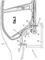
- the folding device (1) may further comprise at least one detection device (34) with which the spatial position and possibly the shape of the to be folded Workpiece area (3) and the rebate edge (5) is received. This can be used to determine where to find the inner and outer flanges to be folded (9,10), which are not visible from the outside in the embodiment shown and are not directly detected.
- the detection device (34) can directly detect the sheet metal edges or flanges (8, 9) in the case of another workpiece design.
- Additional reference marks may e.g. also be mounted on the counter-holder (15) or folding bed when the counter-holder (15) conceals the body-side reference marks (6) in the contact position.
- the detection device (34) can be designed and arranged in different ways.
- FIG. 3 and 7 a variant in the form of an optical detection system with a digital camera is shown, which may be arranged stationary or alternatively by the manipulator (13) according to FIG. 3 is carried. It can be integrated in the aforementioned combination tool or handled as a separate tool.
- the detection device (34) may have a different sensor system, for example an edge-sensing sensor system with or without touch contacts.
- the detection device (34) for example, the reference marks (6) mentioned above are detected with their exact spatial position. From this, the spatial position of the workpiece area to be folded (3), the folded edge (5) and the flanges to be folded (9,10) can be determined. With the detection device (34), the actual data of these workpiece parts are determined on the positioned and tensioned workpiece (2).
- the detection device (34) is also connected to the robot controller (32).
- the detection device (34) as a control interface for a data transmission, the actual data of said workpiece parts being located elsewhere, e.g. in a processing station upstream of the production line, recorded, stored and transmitted to the robot controller via the interface.
- This actual data can be related to a clamping position of the workpiece (2), so that when taking the same clamping position of the workpiece (2) during folding the said actual data result from this clamping position and the location reference reported via the Stezleiters abolishstelle.
- the manipulator (13) guides the seaming tool (12) for bending and folding the flange (s) (9, 10) into the wheel house and for folding or flanging along the seam edge (5) or its contour by means of a control (32). pre-programmed and stored track.
- the web is based on the desired position of the folding contour (5), which in turn represents the course of the hidden flanges (9,10).
- the folding contour (5) can have any shape and is bent in the embodiment shown in a round shape. Alternatively, it may have a straight shape or a curved shape with corners or angles.
- the web can be tracked and corrected if necessary and in the case of any deviations of the actual position from the desired position, e.g. by a base shift.
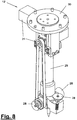
- the folding tool (12) may have any suitable configuration.
- the folding tool (12) as on one side on the seam edge (5) or the flanges or sheet metal edges (9,10) attacking Rollenfalzkopf formed, wherein the counter-holder (15) provides the counter-support.
- FIG. 8 shows an embodiment for this purpose.
- the folding tool (12) has a slender rod-shaped or columnar roller carrier (29) which carries at one end a connection (30) for connection to the hand (14) of the manipulator (13). At the other end of the carrier one or more folding rollers (28) are arranged. In a multiple arrangement, the folding rollers (28) can be arranged on different sides of the roller carrier (29) and have different orientations and different contours, in particular on the roller casing.
- the folding tool (12) can furthermore have a controllable roller drive (31) which is connected to the manipulator control (32) and with which the one or more folding rollers (28) can be driven to rotate. In a multiple arrangement of the folding roller (28), a distribution gear can be arranged.
- the drive (31) is located near the terminal (30) and can with the distant folding rollers (28) and the transfer case in a suitable manner, for example on the in FIG. 8 belt drive shown to be connected.
- At the front end of the roller carrier (29) can also be arranged a centering mandrel for referencing the tool and its Tool Center Points (so-called TCP).
- the sheet metal edges or flanges (8, 9) are bent and folded in one or more steps and angles.
- the folding rollers (28) have a corresponding geometry in order to generate these folding angles when they are moved into contact with the outer flange (10) along the folding contour (5).
- the folding rollers (28) arranged on the circumference or in a circle around the lower end of the carrier can be introduced by the manipulator (13) into the wheel housing (3) and pressed against the flange or flanges (9, 10). By the Infeed and pressing movement, the folding forces are applied for flange bending, which are supported on the counter-holder (15) stationary and stationary to the outside.
- the folding roller (28) can be mounted in a deflectable manner.
- the robot exerts a pulling force on the inner and outer flanges (9, 10) for forming.
- the spring not shown, is arranged such that the seaming roller (28) can yield minimally and can move away from the connection (30). It can be pushed away from the flanges (9, 10) against the resetting spring force.
- the resilient mounting can be present for one or more folding rollers (28). It may be located on the roller carrier (29) or elsewhere.
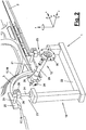
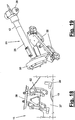
- FIGS. 13 to 22 show the above-mentioned second variant of the folding device (1).
- the molded part (19) and a subsequently explained protective device (57) are arranged on the front side at the edge of the plate cutout.
- a part (50) of the detection device (34) can be located on the front side.
- This detection means (50) can eg as a front in the y direction protruding centering pin can be formed, which engages in a formed as a workpiece opening reference mark (6).
- a stop (59) projecting in the y-direction can be arranged on the front side, which optionally is bent like a hook and which is arranged at the end of the molded part (19) facing away from the detection means (50).
- the stop (59) can engage with the underside of the workpiece, for example the sill adjacent to the wheel arch (3).
- a plurality of counterparts (40,41,42) for Zustellmodule (43,44,45) are arranged, which are differently oriented and aligned transversely to the feed axes in the x, y and z direction ,
- the bearing elements (39) can also be a pre-positioning of the counter-holder (15) on recordings (60) of the frame (22).
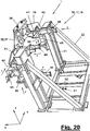
- FIG. 13 shows in plan view a folding device (1) or a folding station with said magazine (53) together with shelves (54) and a plurality of removable counter-holders (15), which are adapted to different types of workpieces, in particular vehicle bodies.
- a multifunctional handling tool (55), which is designed for example as a combination tool for folding and handling. It consists on the one hand of the above-described folding tool (12) and on the other hand from an attached docking device (56) which can cooperate with the connection (38) on the counter-holder (15).
- the folding tool (12) can be aligned during handling along the base plate (37).
- At the folding station can also another manipulator or robot (13) according to FIG. 13 be arranged for equipping the multipart tray (54) and for exchanging counter-holders (15).
- the support device (16) is also modified in the second variant compared to the first embodiment.
- the frame (22) has an upright frame (51) mounted on a carriage (52) and provided with a driven, controllable actuator (61), e.g. a cylinder, in the y-direction to the workpiece (2) can be moved and thereby delivers the on the frame (51) recorded counter-holder (15) in a first step.
- a driven, controllable actuator e.g. a cylinder
- the positioning and fixing device (17,18) consists in the second variant of several Zustellmodulen (43,44,45), which the function of the support elements (23) and their rods (24,25) and drives (27) of the first embodiment take.
- a delivery module (43) is provided for the x-direction.
- For the vertical z-direction there are two parallel feed modules (45) and for the transversely to the workpiece (2) directed y-direction three spatially distributed feed modules (44). This can be done in FIG. 12 shown multi-axis mobilities including axes of rotation can be realized.
- the Zustellmodule (43,44,45) are arranged on the frame (51) with different orientations and cooperate with the aforementioned counterparts (40,41,42).
- FIG. 21 shows the arrangement and distribution of Zustellmodule (43,44,45).
- FIG. 22 is a broken and enlarged view of a vertical Zustellmoduls (45) to see in the Z direction.
- the delivery modules (43,44,45) may be similar and at the same time form part of the positioning device (17) and the fixing device (18). They each have a drive (27) in the form of a cylinder (47) whose piston rod (48) acts as an actuating element and protrudes on both sides of the cylinder housing and on the front side in contact with the transverse plate-shaped counterpart (40,41,42) occurs.
- the counterparts (40, 41, 42) may move relative to the piston rod (48) during positioning.
- a part of the fixing device (18), for example in the form of a clamping device (49) for the piston rod (48) may be arranged.
- the piston rod (48) may be connected to a sensor (46), which is designed, for example, as an odometer or position indicator for detecting the retraction and extension movements of the piston rod (48).
- receptacle (60) consists for example of an upstanding bolt, which is arranged on an elastic base, such as a rubber buffer, and can perform linear and rotational evasive movements when positioning the counter-holder (15).
- receptacles (60) can be arranged on pedestals next to the delivery modules (45) for the z-direction and engage with their bolts in plug-in openings of the bearing elements (39).
- the molded part (19) is adapted and positioned in its rotational position to the actual position of the folding contour (5).
- the distance from the detection means (50) further distanced and in FIG. 21
- Right z-direction feed module (45) the counter-holder (15) and turns it around the y-axis passing through the detecting means (50) until the stop (59) on the workpiece (2) abuts.
- the other Zustellmodul (45) also extends its piston rod (48) accordingly, the counter-holder is supported in the z-direction.
- the forces of the drives (27,47) of the Zustellmodule (45) can be designed and limited to the counterweight and the required lifting and supporting force.
- the delivery module (43) for the x-direction is arranged at a distance above the detection means (50) and registers with its sensor (46) a possible displacement of the counter-holder (15) in the x-direction in the previous delivery and positioning steps. Above all, the delivery module (43) can perform detection services, which is why a clamping device (49) can be dispensed with here and the advance of the drive (27, 47) is set to a correspondingly low force.
- the other feed modules (44) arranged with lateral and vertical offset guide the remaining feed in the y direction and also the tilt adjustment for the shaped part (19) with a possible rotation about the x and z axes and press this with preset force against the workpiece part (3).
- the clamping devices (49) are actuated and secured the position.
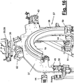
- the aforementioned protective device (57) can be designed as a so-called soft-touch and serves for soft and damage-free feeding of the molded part (19) to the workpiece area (3), in particular the wheel arch.
- FIGS. 15 to 17 clarify this arrangement.
- the protective device (57) has a controllable contact pressure element (58) which can change its dimensions, in particular its thickness, in a controlled manner.
- the pressing member (58) is e.g. as a flexible and inflatable pressure hose made of a soft and elastic material, in particular rubber or another plastic.
- the pressing element (58) is arranged on the outer edge of the molded part (19) and extends along this edge. It can have the same length as the molded part (19). Alternatively, a plurality of shorter pressing elements can be arranged at relevant points distributed over the molding contour.
- the pressing element (58) Before the folding bed (15) or the molded part (19) is applied to the workpiece (2), the pressing element (58) is expanded, in particular inflated, and projects beyond the shaped part (19) in the feed direction y.
- the expansible contact pressure element (58) is connected to a measuring device which can detect the expansion and, for example, can measure the internal pressure in the compressed air-filled pressure hose.
- the cylinders (47) of Delivery modules (44) which provide the advancement of the counter-holder (15) in the y-direction, exert a correspondingly matched counter-pressure force until an equilibrium of forces arises.
- the pressing element (58) then abuts on the workpiece area (3), wherein the molded part (19) is still distanced therefrom.
- all linear movements can be detected during the delivery of the counter-holder (15). From this, the actual position of the molded part (19) or folding bed (15) on the workpiece (2,3) can be determined. These data or possibly differences from predetermined target values can be reported to the robot controller, which evaluates the position data and, if necessary, corrects the programmed folding path of the robot before folding.
- the sensors (46) can be part of the detection device (34). In this variant, it is not necessary to perform a separate measuring travel with the manipulator (13) before folding.
- the delivery modules (43, 44, 45) can be motorized Have spindle drives or other drives (27) with other output elements.
- the shape and design of the counter-holder (15) may vary. Also variable is the shape and design of the folding tool (12) and the detection device (34).
- the folding tool (12) may alternatively have slidable folding runners or other folding means which bend the flanges (9, 10) during a robot-guided movement in the pressing position along the folding contour (5) and the flange profile.
- the folding tool (12) may have one or more fixed or movable folding jaws which extend along the folding contour (5) and the flange profile and by a transverse movement by means of its own drive or by the manipulator transversely against the flanges (9,10 ) and turn or bend them.
- the manipulator (13) positions such a folding tool in the wheel arch and moves it at most transversely to the flange. Further, depending on the workpiece shape and corner shifter, post-forming slide or the like. Be present.
- the folding device (1) can be made flexible and can be converted quickly when changing the type of body parts (2) or in general with a workpiece change. This is important and advantageous in modern bodywork because of the frequent small batch production and the free mix of types.
Landscapes
- Engineering & Computer Science (AREA)
- Mechanical Engineering (AREA)
- Robotics (AREA)
- Bending Of Plates, Rods, And Pipes (AREA)
- Manipulator (AREA)
- Automobile Manufacture Line, Endless Track Vehicle, Trailer (AREA)
Abstract
Claims (15)
- Dispositif de pliage de pièces usinées (2), notamment de parties de carrosserie, le dispositif de pliage (1) comportant au moins un manipulateur (13) mobile selon plusieurs axes doté d'au moins un outil de pliage (12) conjointement entraîné et un contre-support (15) mobile et positionnable contre la zone de pièce usinée (3) à plier, caractérisé en ce que le contre-support (15) est soutenu à l'extérieur de la pièce usinée (2) pour supporter les forces de pliage appliquées avec l'outil de pliage (12).
- Dispositif de pliage selon la revendication 1, caractérisé en ce que le dispositif de pliage (1) comporte un dispositif de détection (34) pour détecter la position et le cas échéant la forme de la zone de pièce usinée (3) à plier.
- Dispositif de pliage selon la revendication 1 ou 2, caractérisé en ce que le dispositif de pliage (1) comporte un dispositif de soutien (16) prévu pour le contre-support (15) et pouvant être soutenu fixement sur place à l'extérieur de la pièce usinée (2), le dispositif de soutien (16) comportant un dispositif de positionnement (17) mobile selon plusieurs axes pour le positionnement et le cas échéant la mise en place du contre-support (15) contre la pièce usinée (2) et un dispositif de fixation (18) pour fixer le dispositif de positionnement (17) et la position du contre-support.
- Dispositif de pliage selon la revendication 1, 2 ou 3, caractérisé en ce que le dispositif de positionnement (17) comporte un châssis (22) pouvant être fixé de façon stationnaire avec plusieurs éléments de soutien (23) prévus pour le contre-support (15) et mobiles et fixables selon plusieurs axes.
- Dispositif de pliage selon l'une quelconque des revendications précédentes, caractérisé en ce que le dispositif de positionnement (17) a plusieurs articulations (26), le dispositif de fixation (18) comportant des moyens de serrage commandables pour bloquer les articulations (26).
- Dispositif de pliage selon l'une quelconque des revendications 1 à 4, caractérisé en ce que le dispositif de positionnement et de fixation (17, 18) comporte plusieurs modules de positionnement (43, 44, 45) dotés de cylindres (47) et des dispositifs de serrage (49), les modules de positionnement (43, 44, 45) comportant des capteurs (46) pour détecter la position réelle du contre-support (15) positionné contre la pièce usinée (2).
- Dispositif de pliage selon l'une quelconque des revendications précédentes, caractérisé en ce que le châssis (22) comporte un cadre (51) et un coulisseau (52), les modules de positionnement (43, 44, 45) étant disposés contre le cadre (51).
- Dispositif de pliage selon l'une quelconque des revendications précédentes, caractérisé en ce que le contre-support (15) comporte un ou plusieurs supports (20, 21, 36) pour réaliser la liaison avec le dispositif de positionnement (17), la pièce moulée (19) étant reliée de façon amovible aux supports (20, 21, 36) et le contre-support (15) étant relié de façon amovible au dispositif de soutien (16).
- Dispositif de pliage selon l'une quelconque des revendications précédentes, caractérisé en ce que le contre-support (15) comporte un support (36) équipé d'une plaque de base (37) et de plusieurs contre-pièces (40, 41, 42) pour les modules de positionnement (43, 44, 45).
- Dispositif de pliage selon l'une quelconque des revendications précédentes, caractérisé en ce que le contre-support (15) comporte un dispositif de protection (57) pour positionner en douceur la pièce moulée (19) ou la plaque de pliage (15) contre la pièce usinée (2).
- Dispositif de pliage selon l'une quelconque des revendications précédentes, caractérisé en ce que le dispositif de protection (57) comporte un élément de compression (58) tendre expansible sur commande et disposé contre la pièce moulée.
- Dispositif de pliage selon l'une quelconque des revendications précédentes, caractérisé en ce que l'outil de pliage (12) prend la forme d'une tête de pliage sur rouleaux s'agrippant unilatéralement sur le bord de pliage (5), le contre-support (15) permettant de réaliser un contre-appui.
- Dispositif de pliage selon l'une quelconque des revendications précédentes, caractérisé en ce que l'outil de pliage (12) comporte un porte-rouleau (29) équipé d'un ou de plusieurs rouleaux de pliage (28) et un raccord (30) pour assurer la liaison avec le manipulateur (13), le ou les rouleaux de pliage (28) comportant un entraînement de rouleaux (31) commandable.
- Procédé de pliage de pièces usinées (2), notamment de pièces de carrosserie, un manipulateur (13) mobile selon plusieurs axes guidant un outil de pliage (12) et un contre-support (15) mobile étant positionné dans la zone de la pièce usinée (3) à plier, caractérisé en ce que les forces de pliage appliquées par l'outil de pliage (12) sont supportées au niveau du contre-support (15) et que le contre-support (15) est soutenu à l'extérieur de la pièce usinée (2).
- Procédé selon la revendication 14, caractérisé en ce que la position de la zone de pièce usinée (3) à plier est détectée par un dispositif de détection (34) et que le manipulateur (13) est commandé de façon correspondante par l'outil de pliage (12).
Priority Applications (1)
| Application Number | Priority Date | Filing Date | Title |
|---|---|---|---|
| PL09721655T PL2276590T3 (pl) | 2008-03-17 | 2009-03-17 | Urządzenie do falcowania i sposób falcowania |
Applications Claiming Priority (2)
| Application Number | Priority Date | Filing Date | Title |
|---|---|---|---|
| DE202008003687U DE202008003687U1 (de) | 2008-03-17 | 2008-03-17 | Falzeinrichtung |
| PCT/EP2009/001970 WO2009115305A2 (fr) | 2008-03-17 | 2009-03-17 | Dispositif et procédé de pliage |
Publications (2)
| Publication Number | Publication Date |
|---|---|
| EP2276590A2 EP2276590A2 (fr) | 2011-01-26 |
| EP2276590B1 true EP2276590B1 (fr) | 2012-05-16 |
Family
ID=40874300
Family Applications (1)
| Application Number | Title | Priority Date | Filing Date |
|---|---|---|---|
| EP09721655A Active EP2276590B1 (fr) | 2008-03-17 | 2009-03-17 | Dispositif et procédé de pliage |
Country Status (5)
| Country | Link |
|---|---|
| EP (1) | EP2276590B1 (fr) |
| DE (1) | DE202008003687U1 (fr) |
| ES (1) | ES2386937T3 (fr) |
| PL (1) | PL2276590T3 (fr) |
| WO (1) | WO2009115305A2 (fr) |
Cited By (2)
| Publication number | Priority date | Publication date | Assignee | Title |
|---|---|---|---|---|
| DE102013018591A1 (de) | 2013-11-06 | 2015-05-07 | Daimler Ag | Verfahren zum Manipulieren eines Bauteils |
| DE102015100659A1 (de) | 2015-01-19 | 2016-07-21 | Fft Produktionssysteme Gmbh & Co. Kg | Bördelsystem, Bördeleinheit und Bördelverfahren für ein autarkes Bördeln |
Families Citing this family (9)
| Publication number | Priority date | Publication date | Assignee | Title |
|---|---|---|---|---|
| DE202009006053U1 (de) * | 2009-04-27 | 2010-09-23 | Kuka Systems Gmbh | Falzeinrichtung |
| DE102011002859A1 (de) * | 2011-01-19 | 2012-07-19 | Bayerische Motoren Werke Aktiengesellschaft | Bördelanlage |
| DE202011000315U1 (de) | 2011-02-11 | 2012-05-21 | Kuka Systems Gmbh | Falzwerkzeug |
| DE102014213063A1 (de) | 2014-07-04 | 2016-01-07 | Volkswagen Aktiengesellschaft | Verfahren und Werkzeugvorrichtung zum Herstellen einer Falzverbindung |
| DE102014221797B4 (de) * | 2014-10-27 | 2019-05-09 | Kuka Systems Gmbh | Verfahren und Robotersystem zur automatischen Bahnermittlung |
| CN108906950B (zh) * | 2018-09-04 | 2023-12-19 | 上汽通用五菱汽车股份有限公司 | 一种预包边装置 |
| CN109760056B (zh) * | 2019-02-02 | 2024-09-06 | 上海市质量监督检验技术研究院 | 家具产品折叠机构智能检测设备 |
| CN110160888B (zh) * | 2019-06-18 | 2022-03-29 | 苏州弗士达科学仪器有限公司 | 一种柔性屏折叠测试装置 |
| DE102021130971A1 (de) * | 2021-11-25 | 2023-05-25 | Ebz Systec Gmbh | Falz- und Messvorrichtung und Verfahren zum Betrieb einer Falz- und Messvorrichtung |
Family Cites Families (12)
| Publication number | Priority date | Publication date | Assignee | Title |
|---|---|---|---|---|
| JP2579530B2 (ja) | 1988-06-24 | 1997-02-05 | マツダ株式会社 | ヘミング成形方法 |
| DE19747292C1 (de) | 1997-10-25 | 1999-01-14 | Thyssen Industrie | Vorrichtung zum Falzen von Blechen, insbesondere Karosserieblechen im Automobilbau |
| DE10012276C1 (de) | 2000-03-14 | 2001-09-06 | Daimler Chrysler Ag | Vorrichtung und Verfahren zum Falzen von Blech |
| DE20114310U1 (de) | 2001-08-31 | 2002-09-19 | KUKA Schweissanlagen GmbH, 86165 Augsburg | Falzeinrichtung für Roboter |
| EP1447155B1 (fr) | 2003-01-20 | 2005-05-04 | COMAU SpA | Outil de sertissage à rouleau et méthode de sertissage |
| DE502005001712D1 (de) * | 2004-09-24 | 2007-11-29 | Edag Eng & Design Ag | Bördelvorrichtung und Bördelverfahren mit Bauteilschutz |
| DE102004046432A1 (de) | 2004-09-24 | 2006-04-13 | Edag Engineering + Design Ag | Vorrichtung zum Falzen eines Karosserieteilrandes und ein damit durchzuführendes Verfahren |
| DE102005012310B3 (de) | 2005-03-17 | 2006-10-12 | Daimlerchrysler Ag | Vorrichtung und Verfahren zum Falzen von Blech, insbesondere Karosserieblech |
| JP4870479B2 (ja) * | 2005-06-21 | 2012-02-08 | 本田技研工業株式会社 | ヘミング加工方法及びヘミング加工装置 |
| JP4523542B2 (ja) * | 2005-12-05 | 2010-08-11 | 本田技研工業株式会社 | ヘミング加工方法及び加工装置 |
| JP5033368B2 (ja) * | 2006-07-07 | 2012-09-26 | 本田技研工業株式会社 | ローラヘミング装置 |
| DE102006054172B8 (de) * | 2006-11-16 | 2010-05-12 | Aksys Gmbh | Verfahren zur Herstellung von nicht-ebenen, insbesondere gewölbten selbsttragenden Bauteilen und danach hergestelltes Bauteil |
-
2008
- 2008-03-17 DE DE202008003687U patent/DE202008003687U1/de not_active Expired - Lifetime
-
2009
- 2009-03-17 EP EP09721655A patent/EP2276590B1/fr active Active
- 2009-03-17 PL PL09721655T patent/PL2276590T3/pl unknown
- 2009-03-17 ES ES09721655T patent/ES2386937T3/es active Active
- 2009-03-17 WO PCT/EP2009/001970 patent/WO2009115305A2/fr not_active Ceased
Cited By (4)
| Publication number | Priority date | Publication date | Assignee | Title |
|---|---|---|---|---|
| DE102013018591A1 (de) | 2013-11-06 | 2015-05-07 | Daimler Ag | Verfahren zum Manipulieren eines Bauteils |
| DE102015100659A1 (de) | 2015-01-19 | 2016-07-21 | Fft Produktionssysteme Gmbh & Co. Kg | Bördelsystem, Bördeleinheit und Bördelverfahren für ein autarkes Bördeln |
| WO2016116414A1 (fr) | 2015-01-19 | 2016-07-28 | Fft Produktionssysteme Gmbh & Co. Kg | Système de sertissage, unité de sertissage et procédé de sertissage permettant un sertissage autonome |
| DE102015100659B4 (de) | 2015-01-19 | 2023-01-05 | Fft Produktionssysteme Gmbh & Co. Kg | Bördelsystem, Bördeleinheit und Bördelverfahren für ein autarkes Bördeln |
Also Published As
| Publication number | Publication date |
|---|---|
| ES2386937T3 (es) | 2012-09-06 |
| EP2276590A2 (fr) | 2011-01-26 |
| WO2009115305A3 (fr) | 2009-12-17 |
| PL2276590T3 (pl) | 2012-10-31 |
| WO2009115305A2 (fr) | 2009-09-24 |
| DE202008003687U1 (de) | 2009-07-16 |
Similar Documents
| Publication | Publication Date | Title |
|---|---|---|
| EP2276590B1 (fr) | Dispositif et procédé de pliage | |
| EP2563546B1 (fr) | Dispositif de traitement | |
| EP2001632B1 (fr) | Combinaison d'un DISPOSITIF DE SERRAGE POUR supporter ET SERRER DES pièces et d'un bras de robot | |
| DE112006001672B4 (de) | Umschlagverfahren mit Umschlagvorrichtung | |
| EP1430989B1 (fr) | Procédé et dispositif de positionnement des éléments à assembler | |
| EP1685915B1 (fr) | Procédé de sertissage avec outil de présertissage et de sertissage | |
| EP1640080B1 (fr) | Dispositif et méthode de sertissage avec protection de la pièce | |
| DE102016225191B4 (de) | Fahrzeugkarosserie-Montagesystem | |
| EP3247511B1 (fr) | Système de sertissage et procédé de sertissage permettant un sertissage autonome | |
| DE102007022102B4 (de) | Bördeln von Bauteilen in Serienfertigungen mit kurzen Taktzeiten | |
| DE112005003561B4 (de) | Walz-Umschlagverfahren und Walz-Umschlagvorrichtung | |
| EP2547469B1 (fr) | Dispositif et procédé de pliage | |
| DE102009018619A1 (de) | Roboterabstützung | |
| EP1599378B1 (fr) | Dispositif et procede d'assemblage | |
| DE69915947T2 (de) | Mehrachsige Rollenfalzvorrichtung | |
| DE4040536A1 (de) | Verfahren und vorrichtung zur montage aeusserer plattenteile eines kraftfahrzeugs | |
| EP1223002A2 (fr) | Dispositif de retenue pour maintenir en position des structures de grande dimension | |
| DE102006014282A1 (de) | Spannvorrichtung zum Aufnehmen und Spannen von Bauteilen | |
| DE69418891T2 (de) | Vorrichtung zum herstellen blechartikeln | |
| DE102005060763A1 (de) | Biegemaschine | |
| DE202009005111U1 (de) | Falzeinrichtung | |
| EP1971516B1 (fr) | Procede et installation de montage de portes sur des carrosseries de vehicules | |
| DE60003947T2 (de) | Verfahren und vorrichtung zur herstellung von dosen | |
| EP4166864A2 (fr) | Procédé, dispositif de montage, cellule de montage et dispositif de préhension multiple pour le montage automatisé d'un cadre pour un élément de conduit d'air | |
| DE102006051245B4 (de) | Fertigungseinrichtung |
Legal Events
| Date | Code | Title | Description |
|---|---|---|---|
| PUAI | Public reference made under article 153(3) epc to a published international application that has entered the european phase |
Free format text: ORIGINAL CODE: 0009012 |
|
| 17P | Request for examination filed |
Effective date: 20101018 |
|
| AK | Designated contracting states |
Kind code of ref document: A2 Designated state(s): AT BE BG CH CY CZ DE DK EE ES FI FR GB GR HR HU IE IS IT LI LT LU LV MC MK MT NL NO PL PT RO SE SI SK TR |
|
| AX | Request for extension of the european patent |
Extension state: AL BA RS |
|
| DAX | Request for extension of the european patent (deleted) | ||
| GRAP | Despatch of communication of intention to grant a patent |
Free format text: ORIGINAL CODE: EPIDOSNIGR1 |
|
| GRAS | Grant fee paid |
Free format text: ORIGINAL CODE: EPIDOSNIGR3 |
|
| GRAA | (expected) grant |
Free format text: ORIGINAL CODE: 0009210 |
|
| AK | Designated contracting states |
Kind code of ref document: B1 Designated state(s): AT BE BG CH CY CZ DE DK EE ES FI FR GB GR HR HU IE IS IT LI LT LU LV MC MK MT NL NO PL PT RO SE SI SK TR |
|
| REG | Reference to a national code |
Ref country code: GB Ref legal event code: FG4D Free format text: NOT ENGLISH |
|
| REG | Reference to a national code |
Ref country code: CH Ref legal event code: EP |
|
| REG | Reference to a national code |
Ref country code: AT Ref legal event code: REF Ref document number: 557796 Country of ref document: AT Kind code of ref document: T Effective date: 20120615 |
|
| REG | Reference to a national code |
Ref country code: IE Ref legal event code: FG4D Free format text: LANGUAGE OF EP DOCUMENT: GERMAN |
|
| REG | Reference to a national code |
Ref country code: DE Ref legal event code: R096 Ref document number: 502009003547 Country of ref document: DE Effective date: 20120712 |
|
| REG | Reference to a national code |
Ref country code: RO Ref legal event code: EPE |
|
| REG | Reference to a national code |
Ref country code: SE Ref legal event code: TRGR |
|
| REG | Reference to a national code |
Ref country code: NL Ref legal event code: VDEP Effective date: 20120516 |
|
| REG | Reference to a national code |
Ref country code: ES Ref legal event code: FG2A Ref document number: 2386937 Country of ref document: ES Kind code of ref document: T3 Effective date: 20120906 |
|
| REG | Reference to a national code |
Ref country code: LT Ref legal event code: MG4D Effective date: 20120516 |
|
| PG25 | Lapsed in a contracting state [announced via postgrant information from national office to epo] |
Ref country code: FI Free format text: LAPSE BECAUSE OF FAILURE TO SUBMIT A TRANSLATION OF THE DESCRIPTION OR TO PAY THE FEE WITHIN THE PRESCRIBED TIME-LIMIT Effective date: 20120516 Ref country code: NO Free format text: LAPSE BECAUSE OF FAILURE TO SUBMIT A TRANSLATION OF THE DESCRIPTION OR TO PAY THE FEE WITHIN THE PRESCRIBED TIME-LIMIT Effective date: 20120816 Ref country code: LT Free format text: LAPSE BECAUSE OF FAILURE TO SUBMIT A TRANSLATION OF THE DESCRIPTION OR TO PAY THE FEE WITHIN THE PRESCRIBED TIME-LIMIT Effective date: 20120516 Ref country code: IS Free format text: LAPSE BECAUSE OF FAILURE TO SUBMIT A TRANSLATION OF THE DESCRIPTION OR TO PAY THE FEE WITHIN THE PRESCRIBED TIME-LIMIT Effective date: 20120916 Ref country code: CY Free format text: LAPSE BECAUSE OF FAILURE TO SUBMIT A TRANSLATION OF THE DESCRIPTION OR TO PAY THE FEE WITHIN THE PRESCRIBED TIME-LIMIT Effective date: 20120516 |
|
| REG | Reference to a national code |
Ref country code: PL Ref legal event code: T3 |
|
| PG25 | Lapsed in a contracting state [announced via postgrant information from national office to epo] |
Ref country code: GR Free format text: LAPSE BECAUSE OF FAILURE TO SUBMIT A TRANSLATION OF THE DESCRIPTION OR TO PAY THE FEE WITHIN THE PRESCRIBED TIME-LIMIT Effective date: 20120817 Ref country code: LV Free format text: LAPSE BECAUSE OF FAILURE TO SUBMIT A TRANSLATION OF THE DESCRIPTION OR TO PAY THE FEE WITHIN THE PRESCRIBED TIME-LIMIT Effective date: 20120516 Ref country code: SI Free format text: LAPSE BECAUSE OF FAILURE TO SUBMIT A TRANSLATION OF THE DESCRIPTION OR TO PAY THE FEE WITHIN THE PRESCRIBED TIME-LIMIT Effective date: 20120516 Ref country code: PT Free format text: LAPSE BECAUSE OF FAILURE TO SUBMIT A TRANSLATION OF THE DESCRIPTION OR TO PAY THE FEE WITHIN THE PRESCRIBED TIME-LIMIT Effective date: 20120917 Ref country code: HR Free format text: LAPSE BECAUSE OF FAILURE TO SUBMIT A TRANSLATION OF THE DESCRIPTION OR TO PAY THE FEE WITHIN THE PRESCRIBED TIME-LIMIT Effective date: 20120516 |
|
| PG25 | Lapsed in a contracting state [announced via postgrant information from national office to epo] |
Ref country code: NL Free format text: LAPSE BECAUSE OF FAILURE TO SUBMIT A TRANSLATION OF THE DESCRIPTION OR TO PAY THE FEE WITHIN THE PRESCRIBED TIME-LIMIT Effective date: 20120516 Ref country code: DK Free format text: LAPSE BECAUSE OF FAILURE TO SUBMIT A TRANSLATION OF THE DESCRIPTION OR TO PAY THE FEE WITHIN THE PRESCRIBED TIME-LIMIT Effective date: 20120516 Ref country code: CZ Free format text: LAPSE BECAUSE OF FAILURE TO SUBMIT A TRANSLATION OF THE DESCRIPTION OR TO PAY THE FEE WITHIN THE PRESCRIBED TIME-LIMIT Effective date: 20120516 Ref country code: EE Free format text: LAPSE BECAUSE OF FAILURE TO SUBMIT A TRANSLATION OF THE DESCRIPTION OR TO PAY THE FEE WITHIN THE PRESCRIBED TIME-LIMIT Effective date: 20120516 Ref country code: SK Free format text: LAPSE BECAUSE OF FAILURE TO SUBMIT A TRANSLATION OF THE DESCRIPTION OR TO PAY THE FEE WITHIN THE PRESCRIBED TIME-LIMIT Effective date: 20120516 |
|
| PLBE | No opposition filed within time limit |
Free format text: ORIGINAL CODE: 0009261 |
|
| STAA | Information on the status of an ep patent application or granted ep patent |
Free format text: STATUS: NO OPPOSITION FILED WITHIN TIME LIMIT |
|
| 26N | No opposition filed |
Effective date: 20130219 |
|
| REG | Reference to a national code |
Ref country code: DE Ref legal event code: R097 Ref document number: 502009003547 Country of ref document: DE Effective date: 20130219 |
|
| PG25 | Lapsed in a contracting state [announced via postgrant information from national office to epo] |
Ref country code: BG Free format text: LAPSE BECAUSE OF FAILURE TO SUBMIT A TRANSLATION OF THE DESCRIPTION OR TO PAY THE FEE WITHIN THE PRESCRIBED TIME-LIMIT Effective date: 20120816 |
|
| BERE | Be: lapsed |
Owner name: KUKA SYSTEMS G.M.B.H. Effective date: 20130331 |
|
| PG25 | Lapsed in a contracting state [announced via postgrant information from national office to epo] |
Ref country code: MC Free format text: LAPSE BECAUSE OF NON-PAYMENT OF DUE FEES Effective date: 20130331 |
|
| REG | Reference to a national code |
Ref country code: CH Ref legal event code: PL |
|
| REG | Reference to a national code |
Ref country code: IE Ref legal event code: MM4A |
|
| PG25 | Lapsed in a contracting state [announced via postgrant information from national office to epo] |
Ref country code: BE Free format text: LAPSE BECAUSE OF NON-PAYMENT OF DUE FEES Effective date: 20130331 Ref country code: LI Free format text: LAPSE BECAUSE OF NON-PAYMENT OF DUE FEES Effective date: 20130331 Ref country code: CH Free format text: LAPSE BECAUSE OF NON-PAYMENT OF DUE FEES Effective date: 20130331 Ref country code: IE Free format text: LAPSE BECAUSE OF NON-PAYMENT OF DUE FEES Effective date: 20130317 |
|
| PG25 | Lapsed in a contracting state [announced via postgrant information from national office to epo] |
Ref country code: MT Free format text: LAPSE BECAUSE OF FAILURE TO SUBMIT A TRANSLATION OF THE DESCRIPTION OR TO PAY THE FEE WITHIN THE PRESCRIBED TIME-LIMIT Effective date: 20120516 |
|
| REG | Reference to a national code |
Ref country code: AT Ref legal event code: MM01 Ref document number: 557796 Country of ref document: AT Kind code of ref document: T Effective date: 20140317 |
|
| PG25 | Lapsed in a contracting state [announced via postgrant information from national office to epo] |
Ref country code: MK Free format text: LAPSE BECAUSE OF FAILURE TO SUBMIT A TRANSLATION OF THE DESCRIPTION OR TO PAY THE FEE WITHIN THE PRESCRIBED TIME-LIMIT Effective date: 20120516 Ref country code: LU Free format text: LAPSE BECAUSE OF NON-PAYMENT OF DUE FEES Effective date: 20130317 Ref country code: HU Free format text: LAPSE BECAUSE OF FAILURE TO SUBMIT A TRANSLATION OF THE DESCRIPTION OR TO PAY THE FEE WITHIN THE PRESCRIBED TIME-LIMIT; INVALID AB INITIO Effective date: 20090317 |
|
| PG25 | Lapsed in a contracting state [announced via postgrant information from national office to epo] |
Ref country code: AT Free format text: LAPSE BECAUSE OF NON-PAYMENT OF DUE FEES Effective date: 20140317 |
|
| REG | Reference to a national code |
Ref country code: FR Ref legal event code: PLFP Year of fee payment: 8 |
|
| REG | Reference to a national code |
Ref country code: FR Ref legal event code: PLFP Year of fee payment: 9 |
|
| REG | Reference to a national code |
Ref country code: FR Ref legal event code: PLFP Year of fee payment: 10 |
|
| P01 | Opt-out of the competence of the unified patent court (upc) registered |
Effective date: 20230528 |
|
| PGFP | Annual fee paid to national office [announced via postgrant information from national office to epo] |
Ref country code: RO Payment date: 20240209 Year of fee payment: 16 Ref country code: DE Payment date: 20231229 Year of fee payment: 16 Ref country code: GB Payment date: 20240108 Year of fee payment: 16 |
|
| PGFP | Annual fee paid to national office [announced via postgrant information from national office to epo] |
Ref country code: TR Payment date: 20240219 Year of fee payment: 16 Ref country code: SE Payment date: 20240103 Year of fee payment: 16 Ref country code: PL Payment date: 20240104 Year of fee payment: 16 Ref country code: IT Payment date: 20240212 Year of fee payment: 16 Ref country code: FR Payment date: 20240103 Year of fee payment: 16 |
|
| PGFP | Annual fee paid to national office [announced via postgrant information from national office to epo] |
Ref country code: ES Payment date: 20240409 Year of fee payment: 16 |
|
| REG | Reference to a national code |
Ref country code: DE Ref legal event code: R119 Ref document number: 502009003547 Country of ref document: DE |
|
| PG25 | Lapsed in a contracting state [announced via postgrant information from national office to epo] |
Ref country code: RO Free format text: LAPSE BECAUSE OF NON-PAYMENT OF DUE FEES Effective date: 20250317 |
|
| REG | Reference to a national code |
Ref country code: SE Ref legal event code: EUG |
|
| GBPC | Gb: european patent ceased through non-payment of renewal fee |
Effective date: 20250317 |
|
| PG25 | Lapsed in a contracting state [announced via postgrant information from national office to epo] |
Ref country code: DE Free format text: LAPSE BECAUSE OF NON-PAYMENT OF DUE FEES Effective date: 20251001 |
|
| PG25 | Lapsed in a contracting state [announced via postgrant information from national office to epo] |
Ref country code: GB Free format text: LAPSE BECAUSE OF NON-PAYMENT OF DUE FEES Effective date: 20250317 |
|
| PG25 | Lapsed in a contracting state [announced via postgrant information from national office to epo] |
Ref country code: FR Free format text: LAPSE BECAUSE OF NON-PAYMENT OF DUE FEES Effective date: 20250331 Ref country code: IT Free format text: LAPSE BECAUSE OF NON-PAYMENT OF DUE FEES Effective date: 20250317 |
|
| PG25 | Lapsed in a contracting state [announced via postgrant information from national office to epo] |
Ref country code: SE Free format text: LAPSE BECAUSE OF NON-PAYMENT OF DUE FEES Effective date: 20250318 |