EP2277676B1 - Système de compactage portable d'un récipient en matière plastique - Google Patents
Système de compactage portable d'un récipient en matière plastique Download PDFInfo
- Publication number
- EP2277676B1 EP2277676B1 EP20100170072 EP10170072A EP2277676B1 EP 2277676 B1 EP2277676 B1 EP 2277676B1 EP 20100170072 EP20100170072 EP 20100170072 EP 10170072 A EP10170072 A EP 10170072A EP 2277676 B1 EP2277676 B1 EP 2277676B1
- Authority
- EP
- European Patent Office
- Prior art keywords
- container
- compacting
- nozzle
- compacted
- vapour
- Prior art date
- Legal status (The legal status is an assumption and is not a legal conclusion. Google has not performed a legal analysis and makes no representation as to the accuracy of the status listed.)
- Active
Links
Images

Classifications
-
- B—PERFORMING OPERATIONS; TRANSPORTING
- B29—WORKING OF PLASTICS; WORKING OF SUBSTANCES IN A PLASTIC STATE IN GENERAL
- B29B—PREPARATION OR PRETREATMENT OF THE MATERIAL TO BE SHAPED; MAKING GRANULES OR PREFORMS; RECOVERY OF PLASTICS OR OTHER CONSTITUENTS OF WASTE MATERIAL CONTAINING PLASTICS
- B29B17/00—Recovery of plastics or other constituents of waste material containing plastics
- B29B17/0026—Recovery of plastics or other constituents of waste material containing plastics by agglomeration or compacting
- B29B17/0047—Compacting complete waste articles
- B29B17/0052—Hollow articles, e.g. bottles
-
- B—PERFORMING OPERATIONS; TRANSPORTING
- B30—PRESSES
- B30B—PRESSES IN GENERAL
- B30B9/00—Presses specially adapted for particular purposes
- B30B9/32—Presses specially adapted for particular purposes for consolidating scrap metal or for compacting used cars
- B30B9/321—Presses specially adapted for particular purposes for consolidating scrap metal or for compacting used cars for consolidating empty containers, e.g. cans
-
- B—PERFORMING OPERATIONS; TRANSPORTING
- B29—WORKING OF PLASTICS; WORKING OF SUBSTANCES IN A PLASTIC STATE IN GENERAL
- B29B—PREPARATION OR PRETREATMENT OF THE MATERIAL TO BE SHAPED; MAKING GRANULES OR PREFORMS; RECOVERY OF PLASTICS OR OTHER CONSTITUENTS OF WASTE MATERIAL CONTAINING PLASTICS
- B29B17/00—Recovery of plastics or other constituents of waste material containing plastics
- B29B17/0026—Recovery of plastics or other constituents of waste material containing plastics by agglomeration or compacting
- B29B17/0047—Compacting complete waste articles
- B29B17/0052—Hollow articles, e.g. bottles
- B29B2017/0057—Externally powered deformation tools, e.g. tools being part of relatively big non domestic installations, powered by motors
-
- B—PERFORMING OPERATIONS; TRANSPORTING
- B29—WORKING OF PLASTICS; WORKING OF SUBSTANCES IN A PLASTIC STATE IN GENERAL
- B29B—PREPARATION OR PRETREATMENT OF THE MATERIAL TO BE SHAPED; MAKING GRANULES OR PREFORMS; RECOVERY OF PLASTICS OR OTHER CONSTITUENTS OF WASTE MATERIAL CONTAINING PLASTICS
- B29B17/00—Recovery of plastics or other constituents of waste material containing plastics
- B29B17/0026—Recovery of plastics or other constituents of waste material containing plastics by agglomeration or compacting
- B29B17/0047—Compacting complete waste articles
- B29B17/0052—Hollow articles, e.g. bottles
- B29B2017/0068—Softening the hollow articles by heat and causing permanent deformation
-
- B—PERFORMING OPERATIONS; TRANSPORTING
- B29—WORKING OF PLASTICS; WORKING OF SUBSTANCES IN A PLASTIC STATE IN GENERAL
- B29K—INDEXING SCHEME ASSOCIATED WITH SUBCLASSES B29B, B29C OR B29D, RELATING TO MOULDING MATERIALS OR TO MATERIALS FOR MOULDS, REINFORCEMENTS, FILLERS OR PREFORMED PARTS, e.g. INSERTS
- B29K2067/00—Use of polyesters or derivatives thereof, as moulding material
-
- Y—GENERAL TAGGING OF NEW TECHNOLOGICAL DEVELOPMENTS; GENERAL TAGGING OF CROSS-SECTIONAL TECHNOLOGIES SPANNING OVER SEVERAL SECTIONS OF THE IPC; TECHNICAL SUBJECTS COVERED BY FORMER USPC CROSS-REFERENCE ART COLLECTIONS [XRACs] AND DIGESTS
- Y02—TECHNOLOGIES OR APPLICATIONS FOR MITIGATION OR ADAPTATION AGAINST CLIMATE CHANGE
- Y02W—CLIMATE CHANGE MITIGATION TECHNOLOGIES RELATED TO WASTEWATER TREATMENT OR WASTE MANAGEMENT
- Y02W30/00—Technologies for solid waste management
- Y02W30/50—Reuse, recycling or recovery technologies
- Y02W30/62—Plastics recycling; Rubber recycling
Definitions
- the present invention relates to the field of systems for the compaction of plastic containers and more particularly to the field of systems for compacting plastic containers by heating the walls of the container.
- the document FR2693144 proposes a device to facilitate this compaction operation.
- the device includes a kettle that maintains a volume of water at a temperature close to 100 ° C.
- the bottle to be compacted is then dipped at one of its ends into the volume of hot water to allow the melting of its plastic walls.
- the bottle, in contact with the bottom of the volume of water is then pressed by a piston which ensures its compaction.
- a device supposes to have conditions of safe handling to avoid any risk of burning. Indeed, the volume of heated water being open, its accidental overturning can be dangerous.
- this device also has the disadvantage of a difficulty in recovering the compacted bottle since it is in the part of the device that contains hot water.
- the document W02007060651 also teaches a compaction device for bottles, this device comprising in particular a jaw which crushes each bottle to be compressed concomitantly with a heating of one of its ends to result in a compacted container according to a predefined shape and volume.
- a compaction device for bottles, this device comprising in particular a jaw which crushes each bottle to be compressed concomitantly with a heating of one of its ends to result in a compacted container according to a predefined shape and volume.
- Such a device nevertheless has the disadvantage of having a relatively slow compaction by not operating a heating and therefore a softening of walls at one end of the container.
- the document EP 1 149 675 also proposes a device for compacting bottles, this device comprising in particular a jaw actuated by a spring and which crushes each bottle to be compressed, this operation being facilitated by a steam production and projection element inside each bottle.
- a device for compacting bottles comprising in particular a jaw actuated by a spring and which crushes each bottle to be compressed, this operation being facilitated by a steam production and projection element inside each bottle.
- Such a device presents.
- the document WO 00/21725 A1 proposes a device for compacting plastic bottles, including in particular a steam generating element associated with a nozzle projecting the vapor formed inside the bottle to be compacted, thereby reducing the mechanical pressure required for the operation.
- a steam generating element associated with a nozzle projecting the vapor formed inside the bottle to be compacted, thereby reducing the mechanical pressure required for the operation.
- the manipulation of such a device is not necessarily easy, given the fact that the bottle to be compacted is not inserted into an enclosure and maintained by side walls.
- the present invention aims to overcome one or more disadvantages: the prior art by providing a system based on a secure operation while allowing a fast and easy domestic compaction.
- the container compacting system is characterized in that the enclosure is adiabatic and inside which is oriented the orifice of at least one nozzle of the steam projection device, means of control of the vapor projection preventing the projection of steam during the opening of the enclosure.
- the container compacting system is characterized in that, the system comprising a nozzle introduced into the container to be compacted at an orifice of the container, the orifice of the nozzle of the steam projection device. opens out inside the container to be compacted.
- the container compaction system is characterized in that at least one jaw of the compression device comprises an orifice through which the nozzle passes.
- the container compaction system is characterized in that the adiabatic enclosure comprises an orifice arranged to allow evacuation of water vapor once compaction of the container is complete.
- the container compaction system is characterized in that the adiabatic enclosure comprises a device for cooling the compacted container.
- the container compacting system is characterized in that it comprises a control and control device connected to the heating resistor, and / or to the steam projection device, and / or to a member of the compression device, and / or at least one cooling device of the compacted container.
- the container compaction system is characterized in that it comprises at least one sensor of the temperature of the container to be compacted and / or the content of the adiabatic enclosure of the system.
- the container compacting system is characterized in that the system comprises at least one device for removing and / or ejecting the compacted container.
- Another object of the invention is to provide a method adapted to the operation of the compacting system of the invention.
- the compacting system of the invention is based on the projection of water vapor inside the walls of a container (6) intended to be compacted and disposed within the system of the invention.
- This water vapor makes it possible to generate a softening of the plastic structure of the container and thus to facilitate the compression and compacting of the container (6) in question.
- the system according to the invention thus comprises a device (8) for producing, supplying and / or recovering water vapor which projects the vapor via one or more nozzles (2a) to the inside the walls of the container (6) to be compacted.
- the production of steam is ensured through the intervention of a heating resistor whose operation is managed from a device (4) for control and control.
- the system also includes a compression device (3a, 3b, 3c, 9) provided with a pair of jaws (3a, 3b) arranged to generate a compression of the container (6) along its main axis.
- the device (3a, 3b, 3c, 9) may have its two jaws mobile during compaction, or a first being movable while the second is fixed.
- This compression device (3a, 3b, 3c, 9) can be operated manually or according to a preferred embodiment by a motor system (3c, 9).
- the jaws of the device (3a, 3b, 3c, 9) are arranged to be adapted to the shape of the container (6) to compact and allow optimal grip to ensure compression.
- the compaction system comprises an adiabatic enclosure (1) in which the jaws of the compression device (3a, 3b, 3c, 9) are arranged to operate.
- the container (6) to be compacted is then positioned inside the adiabatic enclosure (1) between the jaws of the compression device (3a, 3b, 3c, 9).
- the system of the invention comprises a rectilinear nozzle made by a duct oriented along the axis of compression of the system.
- This rectilinear nozzle (2a) thus has a length substantially equal to the length of the container (6) to be compressed.
- the end of the nozzle (2a) is thus arranged to be positioned near the bottom of the container (6), at a distance substantially equal to the height of the container (6) once it is compressed.
- This nozzle (2a) preferably fixed with the frame of the system, is arranged to position at least one vapor jet orifice inside the container to be compressed.
- the container to be compressed, before the compaction step, is threaded on the nozzle (2a) through an orifice, preferably by its neck when this container is a bottle.
- the vapor projection orifice (2b) is then located at the bottom of the bottle.
- This embodiment allows the steam to be directly projected inside the container to be compacted to effect its softening.
- the compression device is provided with a pair of jaws (3a, 3b) of which at least one (3b) of them is movably mounted and sliding along the axis of the container to be compacted.
- the container to be compressed is positioned between these jaws (3a, 3b) so that when this container is a bottle, the neck thereof is positioned against the movable jaw (3b).
- This movable jaw (3b) is preferably slidably mounted along the nozzle (2a), so that this jaw (3b) is traversed by the nozzle (2a) at an orifice.
- the bottle to be compressed (6) when it is threaded on the nozzle (2a) of the system, is then positioned so that its neck is located opposite this sliding orifice of the jaw (3b) on the nozzle (2a). ).
- the steam is projected by the nozzle (2a) at the bottom of the bottle while the movable jaw (3b) slides along the nozzle (2a). by squeezing the bottle at its neck.
- the vapor projection occurs at the bottom of the bottle which is the part of the container that is softened the most quickly, the steam being injected into the bottle also allows the maintenance of heating to all the different walls of the container.
- This embodiment also makes it possible to maintain a projection of vapor inside the container during compaction regardless of the length of the container, but above all independently of the progress of the compaction.
- the compressive force is transmitted along the walls of the bottle to reach the part of the walls softened by the projected vapor where the compression of the bottle takes place.
- the nozzle (2a) also rectilinear, comprises a plurality of steam projection orifice (2b). These orifices (2b) are arranged to be positioned over the entire length of the nozzle (2b) and to allow steam to be projected from the periphery of the body of the nozzle onto the walls of the container (6) to be compacted.
- the vapor projection is operated over the entire length of the nozzle (2a) and homogeneously along the body of the container (6).
- the container (6) is compressed by a pressure exerted by the movable jaw (3b) at its neck and the vapor projection is carried out permanently against the walls of the container ( 6) during compression, a portion of the nozzle of the nozzle orifice (2a) being permanently positioned inside the container (6).
- the vapor projection through one or more orifices (2b) of the nozzle (2a) is performed from inside the container (6), away from the orifice of the container (6).
- This projection of vapor from inside the container (6) then makes it possible firstly to quickly replace the cold air inside the container (6) by displacement by pushing the cold air at the orifice of the container (6) and on the other hand to circulate the projected heat inside the container with an easy movement of heat from inside the container to the outside and an evacuation of the cooled steam at the level of the port of the container (6).
- This setting in motion of the generated heat thus allows an optimization of the softening of the plastic structure of the walls of the container and then facilitate the compression and compacting of the container (6) in question.
- An advantage of these embodiments is to allow, according to a particular non-limiting embodiment of the invention, an integration of the nozzle (2a) in the actuating mechanism of the jaws (3a, 3b).
- the nozzle (2a) may have a thread on its periphery, along its axis, arranged to interact with a thread disposed on the periphery of the sliding orifice of the jaw (3b).
- the nozzle (2a) is then rotatably mounted about its axis relative to the frame of the compaction system.
- the actuation of the rotation of the nozzle (2a) comprises an end mounted on a rotary motor (9).
- This rotary motor (9) is arranged to allow a rotation of the nozzle (2a) about its axis while maintaining a sealed communication of the interior of the nozzle with the device (8) for producing and supplying steam. 'water.
- the rotary motor (9) thus forms the motor system of the device of the invention with a generator (3c).
- the movable jaw (3b) through the tapping of its orifice which interacts with the thread on the periphery of the nozzle (2a), slides along the axis of the nozzle (2a) being held fixed in rotation relative to this same axis.
- This fixed retention in rotation of the movable jaw (3b) can be achieved, for example and without limitation, by means of a rail positioned on an inner wall of the adiabatic wall (1) and arranged along an axis parallel to that of the nozzle and which interacts with a groove on the periphery of the jaw.
- the rotation of the nozzle (2a) about its axis, actuated by the motor (3c) then causes the sliding by translation of the jaw (3b) which remains fixed in rotation relative to the nozzle (2a).
- the manufacture of the nozzle (2a) which is, in this embodiment, the central piece of the compacting system according to the invention, is carried out using a conduit.
- a conduit rectilinear axially and / or having substantially the shape of a rod bored along its axis.
- this conduit has a sufficiently rigid structure not to be deformed and to generate a displacement when it is driven axially in rotation at one of its ends.
- This rectilinear conduit is then overmolded on its periphery by a solidifiable material and can become rigid enough to allow the realization of a thread.
- this overmolding comprises a thread.
- the solidifiable material for overmoulding may be in a nonlimiting manner any plastic or resin, or even ceramic known and adapted to the production of the nozzle of the invention, that is to say, in particular able to withstand the steam diffusion temperatures of the compaction system of the invention.
- vapor projection orifices (2b) are formed on the periphery of the nozzle.
- the projection orifices (2b) are already made on the periphery of the rectilinear conduit; these orifices (2b) are then preserved by avoiding their closure during the overmolding step.
- the adiabatic enclosure (1) may ideally comprise a lid (10) which closes the opening of the enclosure (1) and through which the container (6) to be compacted is positioned in the system.
- a safety device can be associated with this lid (10) so that the system, and in particular the control of the steam projection, can not be put into operation if this lid is not properly closed. This device thus prevents any projection of steam during the opening of the enclosure.
- the safety device is therefore an additional guarantee when preventing the risk of burn accidents.
- the jaw (3a) fixed during compression of the container (6) is formed by the cover of the adiabatic enclosure when it closes the enclosure. This embodiment thus allows a reduction in the number of parts to be machined during the manufacture of the device of the invention.
- the adiabatic enclosure (1) may comprise a device (1b) for evacuation of the steam which is opened once the compacting operation is completed.
- This device (1b) evacuation contributes to cooling the contents of the enclosure (1) and in particular the container (6) so that it can be recovered without risk of burn by the user.
- this device (1b) for steam evacuation is provided with a fan that accelerates the evacuation of heat from the enclosure (1). It is understood that the cooling of the compacted container can be operated by the intervention of any other known device.
- the compaction system according to the invention ideally comprises a device (4) for controlling and controlling the invention which is connected on the one hand to the motor system (3c, 9) of the device (3a, 3b, 3c, 9). compression and secondly to the device (8) for producing and supplying steam or directly to the nozzle of this device (8).
- This control device (4) is ideally connected to one or more sensors (5) which make it possible to provide information on the temperature inside the adiabatic enclosure (1) and / or the container (6) once the latter it is compacted. Furthermore, this control device (4) can also be connected to the cooling device and / or the safety device of the lid.
- the start of compaction operations by the user can be triggered from an interface connected to the device (4) for control and control.
- the lid (10) of the adiabatic enclosure (1) is arranged to recover the container (6) once it is compressed.
- the lid is made to have the shape of a housing (10a) large enough to receive the container (6) compressed.
- This housing (10a) has an opening (10b) intended to be positioned opposite the adiabatic container (1) of the compacting system of the invention to close it.
- This housing (10a) is arranged to hold the container (6) compressed by a plurality of rings (11a, 11b, 11c) of elastic material, for example rubber, having identical external diameters but whose internal diameters are all different. These rings (11a, 11b, 11c) are then mounted and positioned concentrically in the housing (10) of the cover in the plane of the opening (10b) and near the opening (10b) of the housing, so their external diameters are in contact with the inner wall of the housing.
- these rings (11a, 11b, 11c) are arranged relative to each other in the housing (10a) so as to have an internal diameter increasing from the opening (10b) of the housing towards the inside of the housing ( 10a).
- the compressed container is pushed by the movable jaw (3b) into the housing (10a) of the lid (10) through the internal orifices of the elastic rings (11a, 11b, 11c).
- These rings (11a, 11b, 11c) elastic provides an arrangement which defines a space in the housing (10a) adapted to receive a container (6) compressed and able to be retained by the rings of smaller internal diameter.
- the ejection of the compressed container (6) retained in the housing (10) of the lid is ensured by means of a push button (12) which passes through the wall of the lid to press on the compressed container ( 6) and expel it towards the opening (10b) of the housing.
- the temperature of the steam is controlled and continuously managed, in particular by means of the temperature sensors, to ensure optimum melting of the walls of the container (6).
- the security device of the lid (10) of the enclosure may, for example, be unlocked.
- the device (8) for producing, feeding and / or recovering water vapor comprises a connector with, for example, a flexible conduit. This connection then makes it possible to use the device (8) for producing steam as a source for ancillary equipment such as a steam cleaner.
Landscapes
- Engineering & Computer Science (AREA)
- Mechanical Engineering (AREA)
- Environmental & Geological Engineering (AREA)
- Apparatus For Disinfection Or Sterilisation (AREA)
- Separation, Recovery Or Treatment Of Waste Materials Containing Plastics (AREA)
Description
- La présente invention se rapporte au domaine des systèmes destinés à la compaction des récipients en plastique et plus particulièrement au domaine des systèmes destinés à la compaction des récipients en plastique par chauffage des parois du récipient.
- La consommation de boisson liquide s'effectue généralement par leur distribution et leur vente dans des récipients en plastiques, souvent des bouteilles de forme sensiblement cylindrique. Ces récipients plastiques, une fois vides, ont l'inconvénient de prendre de la place et nécessite des containers de récupération dont le volume doit être conséquent pour permettre le stockage de ces récipients avant leur recyclage. Une alternative à ce problème d'encombrement consiste à compacter les bouteilles une fois qu'elles sont vidées et avant que ces dernières ne soient stockées dans un container destiné à rejoindre une déchèterie.
- Le document
FR2693144 - Le document
W02007060651 enseigne également un dispositif de compaction pour bouteilles, ce dispositif comprenant notamment une mâchoire qui écrase chaque bouteille à compresser concomitamment à un chauffage d'une de ses extrémités pour aboutir à un récipient compacté selon une forme et un volume prédéfini. Un tel dispositif présente néanmoins l'inconvénient d'avoir une compaction relativement lente en n'opérant un chauffage et donc un ramollissement dés parois au niveau d'une seule des extrémités du récipient. - Le document
EP 1 149 675 propose également un dispositif de compaction de bouteilles, ce dispositif comprenant notamment une mâchoire actionnée par un ressort et qui écrase chaque bouteille à compresser, cette opération étant facilitée par un élément de production et de projection de vapeur à l'intérieur de chaque bouteille. Un tel dispositif présente. également l'inconvénient d'avoir une compaction lente, dans l'attente du ramollissement de la bouteille à écraser. - Le document
WO 00/21725 A1 - La présente invention a pour objectif de palier un ou plusieurs inconvénients: de l'art antérieur en fournissant un système reposant sur un fonctionnement sécurisé tout en permettant d'effectuer un compactage domestique rapide et facilité.
- Cet objectif est atteint grâce à un système de compactage portable selon la revendication 1.
- Selon une variante de réalisation, le système de compactage de récipient est caractérisé en ce que l'enceinte est adiabatique et à l'intérieur de laquelle est orienté l'orifice d'au moins une buse du dispositif de projection de vapeur, des moyens de commande de la projection de vapeur empêchant la projection de vapeur lors de l'ouverture de l'enceinte.
- Selon une variante de réalisation, le système de compactage de récipient est caractérisé en ce qui, le système comprenant une buse introduite dans le récipient à compacter au niveau d'un orifice du récipient, l'orifice de la buse du dispositif de projection de vapeur débouche à l'intérieur du récipient à compacter.
- Selon une variante de réalisation, le système de compactage de récipient est caractérisé en ce qu'au moins une mâchoire du dispositif de compression comprend un orifice traversé par la buse.
- Selon une variante de réalisation, le système de compactage de récipient est caractérisé en ce que l'enceinte adiabatique comprend un orifice arrangé pour permettre une évacuation de la vapeur d'eau une fois la compaction du récipient terminée.
- Selon une variante de réalisation, le système de compactage de récipient est caractérisé en ce que l'enceinte adiabatique comprend un dispositif de refroidissement du récipient compacté.
- Selon une variante de réalisation, le système de compactage de récipient est caractérisé en ce qu'il comprend un dispositif de contrôle et de commande relié à la résistance chauffante, et/ou au dispositif de projection de vapeur d'eau, et/ou à un organe du dispositif de compression, et/ou à au moins un dispositif de refroidissement du récipient compacté.
- Selon une variante de réalisation, le système de compactage de récipient est caractérisé en ce qu'il comprend au moins un capteur de la température du récipient à compacter et/ou du contenu de l'enceinte adiabatique du système.
- Selon une variante de réalisation, le système de compactage de récipient est caractérisé en ce que le système comprend au moins un dispositif de retrait et/ou d'éjection du récipient compacté.
- Un autre objectif de l'invention est de proposer un procédé adapté au fonctionnement du système de compactage de l'invention.
- Cet objectif est atteint grâce à un procédé de compactage de récipient mettant en jeu un système de compactage selon l'invention, caractérisé en ce que le procédé comprend :
- une étape de positionnement du récipient à compacter entre les mâchoires du dispositif de compaction,
- une étape de diffusion de vapeur d'eau à l'intérieur des parois du récipient à compacter,
- une étape de chauffage des parois du récipient à compacter,
- une étape de rapprochement des mâchoires du dispositif de compression,
- une étape de refroidissement du récipient compacté, et
- une étape de retour d'au moins une des mâchoires dans sa position initiale.
- L'invention, avec ses caractéristiques et avantages, ressortira plus clairement à la lecture de la description faite en référence aux dessins annexés dans lesquels :
- la
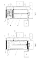
figure 1 représente un premier exemple de réalisation en coupe d'un système selon l'invention et selon une vue latérale, avant compactage, - la
figure 2 représente le premier exemple de réalisation en coupe d'un système selon l'invention et selon une vue latérale, en cours de compactage, - la
figure 3 représente un second exemple de réalisation en coupe d'un système selon l'invention et selon une vue latérale, avant compactage, - la
figure 4 représente le second exemple de réalisation en coupe d'un système selon l'invention et selon une vue latérale, en cours de compactage, - les
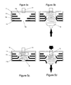
figures 5a, 5b, 5c et 5d présentent un exemple de réalisation d'un couvercle pour un système de compaction selon l'invention dont respectivement le logement est vide, puis reçoit un récipient en compression, stocke le récipient compressé puis éjecte le récipient compressé. - Le système de compactage de l'invention s'appuie sur la projection de vapeur d'eau à l'intérieur les parois d'un récipient (6) destiné à être compacté et disposé à l'intérieur du système de l'invention. Cette vapeur d'eau permet de générer un ramollissement de la structure plastique du récipient et ainsi de faciliter la compression et le compactage du récipient (6) en question.
- Le système selon l'invention comprend ainsi un dispositif (8) de production, d'alimentation et/ou de récupération en vapeur d'eau qui projette la vapeur par l'intermédiaire d'une ou de plusieurs buses (2a) à l'intérieur des parois du récipient (6) à compacter. La production de vapeur d'eau est assurée grâce à l'intervention d'une résistance chauffante dont le fonctionnement est géré depuis un dispositif (4) de commande et de contrôle. Le système comprend également un dispositif (3a, 3b, 3c, 9) de compression muni d'une paire de mâchoires (3a, 3b) arrangée pour générer une compression du récipient (6) selon son axe principal. Selon le mode de réalisation, le dispositif (3a, 3b, 3c, 9) peut présenter ses deux mâchoires mobiles lors de la compaction, ou bien une première étant mobile tandis que la seconde est fixe. Ce dispositif (3a, 3b, 3c, 9) de compression peut être actionné manuellement ou selon un mode de réalisation préféré par un système moteur (3c, 9). Selon un mode de réalisation particulier, les mâchoires du dispositif (3a, 3b, 3c, 9) sont arrangées pour être adaptées à la forme du récipient (6) à compacter et en permettre une prise optimale pour en assurer la compression.
- Selon un mode de réalisation préféré de l'invention, le système de compactage comporte une enceinte adiabatique (1) dans laquelle les mâchoires du dispositif (3a, 3b, 3c, 9) de compression sont arrangées pour opérer. Lorsque le système est utilisé, le récipient (6) à compacter est alors positionné à l'intérieur de l'enceinte adiabatique (1) entre les mâchoires du dispositif (3a, 3b, 3c, 9) de compression.
- Selon un mode de réalisation préféré, le système de l'invention comprend une buse rectiligne réalisée par un conduit orienté selon l'axe de compression du système. Cette buse (2a) rectiligne présente alors ainsi une longueur sensiblement égale à la longueur du récipient (6) à compresser. L'extrémité de la buse (2a) est ainsi arrangée pour être positionnée à proximité du cul du récipient (6), à une distance sensiblement égale à la hauteur du récipient (6) une fois celui-ci compressé. Cette buse (2a), préférentiellement fixe avec le bâti du système, est disposée de façon à positionner au moins un orifice de projection de vapeur à l'intérieur du récipient à compresser. Le récipient à compresser, avant l'étape de compaction, est enfilé sur la buse (2a) par un orifice, de façon préférée, par son goulot lorsque ce récipient est une bouteille.
- Selon un premier mode de réalisation, l'orifice de projection (2b) de vapeur se trouve alors situé au niveau du cul de la bouteille. Ce mode de réalisation permet à la vapeur d'être directement projetée à l'intérieur du récipient à compacter pour effectuer son ramollissement. Le dispositif de compression est muni d'une paire de mâchoire (3a, 3b) dont au moins l'une (3b) d'entre elles est montée mobile et coulissante selon l'axe du récipient à compacter. Le récipient à compresser est positionné entre ces mâchoires (3a, 3b) de sorte que, lorsque ce récipient est une bouteille, le goulot de celle-ci soit positionné contre la mâchoire mobile (3b). Cette mâchoire (3b) mobile est préférentiellement montée coulissante le long de la buse (2a), de sorte que cette mâchoire (3b) est traversée par la buse (2a) au niveau d'un orifice. La bouteille à compresser (6), lorsqu'elle est enfilée sur la buse (2a) du système, est alors positionnée de sorte que son goulot est situé en regard de cet orifice de coulissement de la mâchoire (3b) sur la buse (2a).
- Selon le mode de réalisation précédemment détaillé, lors de la compression de la bouteille, la vapeur est projetée par la buse (2a) au niveau du cul de la bouteille tandis que la mâchoire (3b) mobile coulisse le long de la buse (2a) en pressant la bouteille au niveau de son goulot. Bien que la projection de vapeur s'effectue au niveau du cul de la bouteille qui est la partie du récipient qui est le plus rapidement ramolli, la vapeur en étant injectée à l'intérieure de la bouteille permet également le maintien d'un chauffage à l'ensemble des différentes parois du récipient. Ce mode de réalisation permet encore de conserver une projection de vapeur à l'intérieur du récipient en cours de compactage indépendamment de la longueur du récipient, mais surtout indépendamment de l'état d'avancement de la compaction. Par ailleurs, bien que la projection de vapeur s'opère au niveau du cul de la bouteille et que la pression de la mâchoire (3b) mobile s'effectue au niveau du goulot de la bouteille, la force de compression est transmise le long des parois de la bouteille pour atteindre la partie des parois ramollie par la vapeur projetée où s'effectue la compression de la bouteille. Une fois que les mâchoires (3a, 3b) du système de compactage sont rapprochées et que le récipient (6) est compacté, l'extrémité de la buse (2a) est alors positionnée à proximité du cul du récipient (6), à une distance sensiblement égale à la hauteur du récipient (6) compressé. L'extrémité de la buse (2a) se trouve alors située au niveau du goulot du récipient (6) compressé et permet au récipient (6) d'être facilement retiré de la buse (2a) et du système de compactage.
- Selon un autre mode de réalisation, la buse (2a), également rectiligne, comprend une pluralité d'orifice de projection (2b) de vapeur. Ces orifices (2b) sont arrangés pour être positionnés sur toute la longueur de la buse (2b) et permettre une projection de vapeur depuis la périphérie du corps de la buse sur les parois du récipient (6) à compacter. Ainsi la projection de vapeur est opérée sur toute la longueur de la buse (2a) et de façon homogène le long du corps du récipient (6). Au cours de la compaction du récipient (6), le récipient (6) est compressé par une pression exercée par la mâchoire (3b) mobile au niveau de son goulot et la projection de vapeur est effectuée de façon permanente contre les parois du récipient (6) en cours de compression, une partie des orifices de projection de la buse (2a) se trouvant en permanence positionnée à l'intérieur du récipient (6).
- Dans ces deux modes de réalisation, la projection de vapeur par un ou plusieurs orifices (2b) de la buse (2a) est effectuée depuis l'intérieur du récipient (6), à distance de l'orifice du récipient (6). Cette projection de vapeur depuis l'intérieur du récipient (6) permet alors d'une part de remplacer rapidement l'air froid à l'intérieur du récipient (6) par déplacement en repoussant l'air froid au niveau de l'orifice du récipient (6) et d'autre part de faire circuler la chaleur projetée à l'intérieur du récipient avec un déplacement facilité de la chaleur depuis l'intérieur du récipient vers l'extérieur et une évacuation de la vapeur refroidie au niveau de l'orifice du récipient (6).
- Cette mise en mouvement de la chaleur générée permet ainsi une optimisation du ramollissement de la structure plastique des parois du récipient et alors faciliter la compression et le compactage du récipient (6) en question.
- Un avantage de ces modes de réalisation est de permettre, selon un mode de réalisation particulier non limitatif de l'invention, une intégration de la buse (2a) dans le mécanisme d'actionnement des mâchoires (3a, 3b). En effet, la buse (2a) peut comporter un filetage sur sa périphérie, le long de son axe, arrangé pour interagir avec un taraudage disposé sur le pourtour de l'orifice de coulissement de la mâchoire (3b). La buse (2a) est alors montée pivotante en rotation autour de son axe par rapport au bâti du système de compactage. Selon un exemple de réalisation de l'actionnement de la rotation de la buse (2a), celle-ci comporte une extrémité montée sur un moteur rotatif (9). Ce moteur rotatif (9) est arrangé pour permettre une rotation de la buse (2a) autour de son axe tout en conservant une communication étanche de l'intérieur de la buse avec le dispositif (8) de production et d'alimentation en vapeur d'eau. Le moteur rotatif (9) forme ainsi le système moteur du dispositif de l'invention avec un générateur (3c). Lorsque la buse (2a) est actionnée par le système moteur (3c, 9), il est indispensable que la buse (2a) présente une structure axiale rectiligne avec une certaine rigidité de sorte que lorsqu'elle est mise en rotation, cette buse (2a) ne présente pas un écartement de son axe par rapport à l'axe de rotation du moteur rotatif (9). Lors de la rotation de la buse (2a) autour de son axe, la mâchoire mobile (3b) grâce au taraudage de son orifice qui interagit avec le filetage sur le pourtour de la buse (2a), coulisse selon l'axe de la buse (2a) en étant maintenue fixe en rotation par rapport à ce même axe. Ce maintien fixe en rotation de la mâchoire mobile (3b) peut être réalisé, par exemple et de façon non limitative, grâce à un rail positionnée sur une paroi interne de la paroi adiabatique (1) et arrangé selon un axe parallèle à celui de la buse et qui interagit avec une rainure sur la périphérie de la mâchoire. La rotation de la buse (2a) autour de son axe, actionnée par le moteur (3c), entraine alors le coulissement par translation de la mâchoire (3b) qui demeure fixe en rotation par rapport à la buse (2a).
- Cette intégration de la buse (2a) dans le mécanisme d'actionnement permet de réduire le nombre de pièces à monter pour construire le système de compactage. De plus en combinant le mécanisme de rapprochement des mâchoires (3a, 3b) au mécanisme de diffusion de vapeur, le système de l'invention permet un gain de place.
- Par ailleurs, selon un mode de réalisation préféré mais non limitatif, la fabrication de la buse (2a) qui est, dans ce mode de réalisation, la pièce centrale du système de compactage selon l'invention, est effectuée par utilisation d'un conduit rectiligne axialement et/ou présentant sensiblement la forme d'une tige alésée selon son axe. Idéalement, ce conduit comporte une structure suffisamment rigide pour ne pas être déformée et générer un débattement lorsqu'elle est entraînée axialement en rotation au niveau d'une de ses extrémités. Ce conduit rectiligne est alors surmoulé sur sa périphérie par une matière solidifiable et pouvant devenir suffisamment rigide pour permettre la réalisation d'un filetage. Selon un mode de réalisation particulier de l'étape de surmoulage, ce surmoulage comporte un filetage. La matière solidifiable pour le surmoulage peut être de façon non limitative tout plastique ou résine, voire céramique connu et adapté à la réalisation de la buse de l'invention, c'est-à-dire notamment capable de résister aux températures de diffusion de la vapeur d'eau du système de compactage de l'invention.
- Dans une dernière étape de la fabrication de la buse (2a), des orifices (2b) de projection de vapeur sont réalisé sur la périphérie de la buse. Dans une alternative de réalisation, les orifices de projection (2b) sont déjà réalisés sur la périphérie du conduit rectiligne ; ces orifices (2b) sont alors conservés en évitant leur obturation au cours de l'étape de surmoulage.
- L'enceinte adiabatique (1) peut idéalement comprendre un couvercle (10) qui referme l'ouverture de l'enceinte (1) et par laquelle le récipient (6) à compacter est positionné dans le système. Un dispositif de sécurité peut être associé à ce couvercle (10) de sorte que le système, et notamment la commande de la projection de vapeur, ne peut pas être mis en fonctionnement si ce couvercle n'est pas correctement refermé. Ce dispositif permet ainsi d'empêcher toute projection de vapeur lors de l'ouverture de l'enceinte. Le dispositif de sécurité est donc une garanti supplémentaire quand à la prévention de risques d'accidents par brûlure.
- Selon un mode de réalisation particulier, la mâchoire (3a) fixe lors de la compression du récipient (6) est réalisée par le couvercle de l'enceinte adiabatique lorsque celui-ci ferme l'enceinte. Ce mode de réalisation permet ainsi une réduction du nombre de pièces à usiner lors de la fabrication du dispositif de l'invention.
- De même, l'enceinte adiabatique (1) peut comprendre un dispositif (1 b) d'évacuation de la vapeur qui est ouvert une fois que l'opération de compactage est terminée. Ce dispositif (1 b) d'évacuation participe au refroidissement du contenu de l'enceinte (1) et notamment du récipient (6) afin que celui-ci puisse être récupéré sans risque de brûlure par l'utilisateur. Selon un mode de réalisation particulier, ce dispositif (1 b) d'évacuation de vapeur est muni d'un ventilateur qui permet d'accélérer l'évacuation de la chaleur de l'enceinte (1). Il est entendu que le refroidissement du récipient compacté peut être opéré par l'intervention de tout autre dispositif connu.
- Le système de compactage selon l'invention comprend idéalement un dispositif (4) de commande et de contrôle de l'invention qui est connecté d'une part au système moteur (3c, 9) du dispositif (3a, 3b, 3c, 9) de compression et d'autre part au dispositif (8) de production et d'alimentation en vapeur d'eau ou directement à la buse de ce dispositif (8). Ce dispositif (4) de commande est idéalement connecté à un ou plusieurs capteurs (5) qui permettent de renseigner sur la température à l'intérieur de l'enceinte adiabatique (1) et/ou du récipient (6) une fois que celui-ci est compacté. Par ailleurs, ce dispositif (4) de commande peut également être connecté au dispositif de refroidissement et/ou au dispositif de sécurité du couvercle.
- Le dispositif (4) de commande et de contrôle gère les opérations successives de compactage du récipient notamment en ne déclenchant la projection de vapeur dans l'enceinte adiabatique (1) que lorsque celle-ci est reconnue par le dispositif de sécurité comme étant hermétiquement fermée par l'utilisateur. Une fois que le récipient à compacter est positionné entre les mâchoires du dispositif (3a, 3b, 3c, 9) de compression, le procédé de compactage opéré par le système de l'invention comprend :
- une étape de diffusion de vapeur d'eau à l'intérieur des parois du récipient (6) disposé dans l'enceinte (1) du système, ce qui conduit au réchauffement et au ramollissement des parois du récipient à compacter, la diffusion de vapeur pouvant également s'opérer directement à l'intérieur du récipient à compacter,
- une étape de rapprochement des mâchoires (3a, 3b) du dispositif (3a, 3b, 3c) de compression par déplacement d'au moins une des mâchoires,
- une étape d'évacuation de la vapeur dans l'enceinte adiabatique,
- une étape de retrait du récipient compacté et
- une étape de retour des mâchoires dans leurs positions respectives initiales.
- Selon un mode de réalisation particulier, le lancement des opérations de compactage par l'utilisateur peut être déclenché depuis une interface reliée au dispositif (4) de commande et de contrôle.
- Une fois que le récipient est compacté par les mâchoires du dispositif de compression, celui-ci est retiré ou éjecté soit manuellement, soit par l'intermédiaire d'un dispositif automatisé d'éjection pour rejoindre un moyen de stockage (7) formé par un réceptacle approprié. Cette opération d'éjection peut être effectuée soit avant que les mâchoires ne se desserrent pour retourner dans leur position initiale, soit à la fin de la compression avant le retour de ces mâchoires en position ouverte. Selon une variante de réalisation du dispositif d'éjection compatible avec les différentes variantes de l'invention déjà énoncée, le couvercle (10) de l'enceinte adiabatique (1) est arrangé pour récupérer le récipient (6) une fois que celui-ci est compressé. Dans un exemple de réalisation non limitatif, le couvercle est réalisé de façon à présenter la forme d'un logement (10a) suffisamment large pour recevoir le récipient (6) compressé. Ce logement (10a) comporte une ouverture (10b) destinée à être positionnée en regard du récipient adiabatique (1) du système de compactage de l'invention pour le refermer. Ce logement (10a) est arrangé pour maintenir le récipient (6) comprimé grâce à une pluralité d'anneaux (11a, 11b, 11c) en matière élastique, par exemple en caoutchouc, comportant des diamètres externes identiques mais dont les diamètres internes sont tous différents. Ces anneaux (11a, 11b, 11c) sont alors montés et positionnés de façon concentrique dans le logement (10) du couvercle dans le plan de l'ouverture (10b) et à proximité de l'ouverture (10b) du logement, de sorte que leurs diamètres externes soit en contact avec la paroi interne du logement. De plus, ces anneaux (11a, 11b, 11c) sont arrangés les uns par rapport aux autres dans le logement (10a) de façon à présenter un diamètre interne croissant depuis l'ouverture (10b) du logement vers l'intérieur du logement (10a). Lors de la compression du récipient (6), le récipient comprimé est repoussé par la mâchoire mobile (3b) dans le logement (10a) du couvercle (10) au travers des orifices internes des anneaux (11a, 11b, 11c) élastiques. Ces anneaux (11a, 11b, 11c) élastiques réalise un arrangement qui définit un espace dans le logement (10a) adapté pour y recevoir un récipient (6) compressé et capable d'être retenu grâce aux anneaux de diamètre interne plus réduit.
- Selon un exemple de réalisation non-limitatif, l'éjection du récipient compressé (6) retenu dans le logement (10) du couvercle est assuré grâce à un bouton poussoir (12) qui traverse la paroi du couvercle pour appuyer sur le récipient compressé (6) et l'expulser vers l'ouverture (10b) du logement.
- Il convient de noter qu'au cours du procédé de compaction, la température de la vapeur est contrôlée et gérée en permanence, notamment grâce aux capteurs de température, pour assurer une fusion optimale des parois du récipient (6).
- Lors du refroidissement, lorsque la température à l'intérieur de l'enceinte adiabatique est inférieure à une température seuil, un signal est transmis au niveau de l'interface utilisateur pour prévenir de l'ouverture sécurisée de l'enceinte. De même, le dispositif de sécurité du couvercle (10) de l'enceinte peut, par exemple, être déverrouillé.
- Selon une particularité de réalisation originale, le dispositif (8) de production, d'alimentation et/ou de récupération en vapeur d'eau comporte une connectique avec, par exemple, un conduit flexible. Cette connectique permet alors d'utiliser le dispositif (8) de production de vapeur comme source pour un appareillage annexe tel qu'un nettoyeur vapeur.
- Il doit être évident pour les personnes versées dans l'art que la présente invention permet des modes de réalisation sous de nombreuses autres formes spécifiques sans l'éloigner du domaine d'application de l'invention comme revendiqué. Par conséquent, les présents modes de réalisation doivent être considérés à titre d'illustration mais peuvent être modifiés dans le domaine défini par la portée des revendications jointes.
Claims (13)
- Système de compactage portable d'au moins un récipient (6) dont les parois présentent une structure à base de matière plastique comprenant au moins un dispositif de compression (3a, 3b, 3c, 9) formant une enceinte munie d'au moins une ouverture et d'au moins une paire de mâchoires (3a, 3b) entre lesquelles au moins un récipient (6) à compacter est destiné à être positionné, le système comprenant un dispositif (2) de production et d'alimentation de vapeur réguléé par une résistance chauffante connectée à un thermostat, le dispositif (2) de production et d'alimentation de vapeur étant associé à un dispositif de projection de vapeur d'eau à l'intérieur des parois du récipient à compacter, le dispositif de projection de vapeur étant réalisé par une buse (2a) destinée à être introduite dans le récipient (6) et dont l'orifice de projection (2b) de vapeur se trouve situé au niveau du culot du récipient, la buse (2a) étant un élément du mécanisme de rapprochement des mâchoires (3a, 3b) lors de la compression, caracterisé en ce que la mâchoire (3b) du dispositif de compression (3a, 3b, 3c, 9) est une mâchoire montée coulissante le long de l'axe de la buse (2a) au niveau d'un orifice traversé par la buse (2a).
- Système de compactage de récipient selon la revendication 1, caractérisé en ce que la buse (2a) est orientée séton l'axe du récipient (6).
- Système de compactage de récipient selon une des revendications précédentes, caractérisé en ce que la buse (2a) comporte une pluralité d'orifices (2b) de diffusion disposés sur au moins une partie de sa longueur.
- Système de compactage de récipient selon une des revendications précédentes, caractérisé en ce que la buse (2a) comporte un orifice (2c) de diffusion de vapeur dans le récipient (6) positionné à une extrémité de la buse (2a).
- Système de: compactage de récipient selon une des revendications précédentes, caractérisé en ce que la buse (2a) comporte un filetage disposé sur la périphérie de son axe pour actionner le déplacement d'au moins la première mâchoire (3b) par rapport à la seconde mâchoire (3a).
- Système de compactage de récipient selon une des revendications précédentes, caractérisé en ce que le système comprend une enceinte adiabatique (1) à l'intérieur de laquelle est orientée la buse (2a) du dispositif de projection de vapeur et des moyens de commande de la projection de vapeur empêchant la projection de vapeur lors de l'ouverture de l'enceinte (1).
- Système de compactage de récipient selon au moins la revendication 5, caractérisé en ce que: la buse (2a) est actionnée en rotation autour de son axe par un système moteur (3c, 9) pour interagir avec le taraudage d'un orifice d'une mâchoire (3b) du dispositif de compression et entrainer la translation la mâchoire (3b) le long de la buse (2a).
- Système de compactage de récipient selon au moins la revendication 6, caractérisé en ce que l'enceinte adiabatique comprend un orifice (1 b) arrangé pour permettre une évacuation de la vapeur d'eau une fois la compaction du récipient (6) terminée.
- Système de compactage de récipient selon au moins la revendication 6, caractérisé en ce que l'enceinte adiabatique comprend un dispositif de refroidissement du récipient compacté.
- Système de compactage de récipient selon une des revendications précédentes, caractérisé en ce que le système de compactage comprend un dispositif (4) de contrôle et de commande relié à la résistance chauffante, et/ou au dispositif de projection de vapeur d'eau, et/ou à un organe du dispositif (3a, 3b, 3c, 9) de compression, et/ou à au moins un dispositif de refroidissement du récipient compacté.
- Système de compactage de récipient selon une des revendications précédentes, caractérisé en ce que le système comprend au moins un capteur (5) de la température du récipient à compacter et/ou du contenu de (l'enceinte (1) adiabatique du système.
- Système de compactage de récipient selon une des revendications précédentes, caractérisé en ce que le système comprend au moins un dispositif de retrait et/ou d'éjection du récipient compacté.
- Procédé de compactage de récipient mettant en jeu un système de compactage selon une des revendication précédentes caractérisé en ce que le procédé comprend :- une étape de positionnement du récipient à compacter entre les mâchoires du dispositif de compaction,- une étape de diffusion de vapeur d'eau à l'intérieur des parois du récipient à compacter,- une étape de chauffage des parois du récipient à compacter,- une étape de rapprochement des mâchoires du dispositif de compression,- une étape de refroidissement du récipient compacté, et- une étape de retour d'au moins une des mâchoires dans sa position initiale.
Applications Claiming Priority (1)
| Application Number | Priority Date | Filing Date | Title |
|---|---|---|---|
| FR0903656A FR2948312B1 (fr) | 2009-07-24 | 2009-07-24 | Systeme de compactage portable d'un recipient en matiere plastique |
Publications (2)
| Publication Number | Publication Date |
|---|---|
| EP2277676A1 EP2277676A1 (fr) | 2011-01-26 |
| EP2277676B1 true EP2277676B1 (fr) | 2012-11-14 |
Family
ID=41723135
Family Applications (1)
| Application Number | Title | Priority Date | Filing Date |
|---|---|---|---|
| EP20100170072 Active EP2277676B1 (fr) | 2009-07-24 | 2010-07-20 | Système de compactage portable d'un récipient en matière plastique |
Country Status (4)
| Country | Link |
|---|---|
| EP (1) | EP2277676B1 (fr) |
| ES (1) | ES2397252T3 (fr) |
| FR (1) | FR2948312B1 (fr) |
| PT (1) | PT2277676E (fr) |
Cited By (1)
| Publication number | Priority date | Publication date | Assignee | Title |
|---|---|---|---|---|
| CN109176996A (zh) * | 2018-08-15 | 2019-01-11 | 安徽奥丰汽车配件有限公司 | 一种用于微型汽车底盘缓冲块的高硬度橡胶硫化设备 |
Families Citing this family (2)
| Publication number | Priority date | Publication date | Assignee | Title |
|---|---|---|---|---|
| US20130233186A1 (en) * | 2012-03-09 | 2013-09-12 | Yann Morez | Bottle compaction system and method |
| FR3132290B1 (fr) * | 2022-01-28 | 2024-02-23 | Bogos Valery | Compacteur domestique de contenants en matière plastique vides |
Family Cites Families (6)
| Publication number | Priority date | Publication date | Assignee | Title |
|---|---|---|---|---|
| JP2588062B2 (ja) * | 1990-12-27 | 1997-03-05 | 秀博 柏木 | プラスチック成形品廃棄物の再生処理方法ならびにその装置 |
| FR2693144B1 (fr) | 1992-07-03 | 1994-10-28 | Andre Gros | Dispositif portable destiné à la destruction des bouteilles plastiques ménagères utilisées comme emballages. |
| IT1302368B1 (it) * | 1998-10-12 | 2000-09-05 | Salvatore Apicella | Dispositivo per ridurre il volume di bottiglie termoplastiche vuotemediante l'uso di vapore |
| IT251784Y1 (it) * | 2000-04-28 | 2004-01-20 | Interpump Engineering Srl | Dispositivo per la compattazione di piccoli contenitori sintetici aperdere |
| WO2005077629A1 (fr) * | 2004-02-13 | 2005-08-25 | Thomas Cribb | Dispositif d'ecrasement de bouteilles en plastique portatif |
| WO2007060651A2 (fr) | 2005-11-25 | 2007-05-31 | Recise Ltd. | Systeme pour reduire le bouteilles plastique en balles de formes repetables |
-
2009
- 2009-07-24 FR FR0903656A patent/FR2948312B1/fr active Active
-
2010
- 2010-07-20 PT PT101700722T patent/PT2277676E/pt unknown
- 2010-07-20 ES ES10170072T patent/ES2397252T3/es active Active
- 2010-07-20 EP EP20100170072 patent/EP2277676B1/fr active Active
Cited By (2)
| Publication number | Priority date | Publication date | Assignee | Title |
|---|---|---|---|---|
| CN109176996A (zh) * | 2018-08-15 | 2019-01-11 | 安徽奥丰汽车配件有限公司 | 一种用于微型汽车底盘缓冲块的高硬度橡胶硫化设备 |
| CN109176996B (zh) * | 2018-08-15 | 2020-11-03 | 安徽奥丰汽车配件有限公司 | 一种用于微型汽车底盘缓冲块的高硬度橡胶硫化设备 |
Also Published As
| Publication number | Publication date |
|---|---|
| FR2948312B1 (fr) | 2014-07-04 |
| FR2948312A1 (fr) | 2011-01-28 |
| ES2397252T3 (es) | 2013-03-05 |
| EP2277676A1 (fr) | 2011-01-26 |
| PT2277676E (pt) | 2012-12-21 |
Similar Documents
| Publication | Publication Date | Title |
|---|---|---|
| EP2146901B1 (fr) | Appareil menager de conservation de bouteilles, notamment de bouteilles de vin debouchees et/ou partiellement consommees | |
| CA2844778C (fr) | Pipette a deplacement positif presentant une fonction d'ejection amelioree | |
| FR2940439A1 (fr) | Dispositif pour le transfert d'un milieu | |
| WO2017144477A1 (fr) | Appareil de fabrication d'une boisson | |
| EP3210746B1 (fr) | Dispositif de séparation pour moule comprenant une chaîne de maillons articulés entre eux | |
| EP2277676B1 (fr) | Système de compactage portable d'un récipient en matière plastique | |
| EP3692289A1 (fr) | Robinet et dispositif de stockage et de distribution de fluide sous pression | |
| EP1590049A1 (fr) | Extincteur d'incendie comportant un reservoir en matiere plastique | |
| EP1943146B1 (fr) | Dispositif de remplissage en liquide de recipient aerosol, installation de remplissage apte a recevoir un tel dispositif et capuchon et recipient aerosol equipe d'un tel dispositif de remplissage | |
| EP0323315B1 (fr) | Conditionnement, tel que bouteille, bocal ou autre récipient similaire, joint d'étanchéité pour le dit conditionnement et procédé de fabrication du dit joint d'étanchéité | |
| FR3035667A1 (fr) | Appareil electromenager de repassage comportant un generateur de vapeur muni d'un orifice de vidange | |
| EP3131829B1 (fr) | Distributeur de produit fluide. | |
| EP4479120B1 (fr) | Distributeur de produit fluide | |
| EP1027278B1 (fr) | Robinet de distribution de liquide | |
| FR3074419A1 (fr) | Paillette pour la conservation cryogenique d'une dose de substance a base liquide, ensemble la comportant et procede de vidage de cette paillette | |
| EP0466564A1 (fr) | Récipient démontable, pouvant supporter une pression interne | |
| WO1989000952A1 (fr) | Dispositif de remplissage en atmosphere controlee | |
| EP3285623B1 (fr) | Système de détection de coincement pour machine de production de boissons par infusion | |
| CA3172189C (fr) | Dispositif de conditionnement et de distribution de produit avec securite enfant | |
| EP2146923B1 (fr) | Coiffe de fermeture pour conteneur adapté pour le stockage de liquides carbonates, et conteneur pourvu d'une telle coiffe | |
| FR3048170A1 (fr) | Appareil de fabrication d'une boisson | |
| FR2967410A1 (fr) | Dispositif et procede pour le dosage d'un produit foisonne. | |
| FR3132703A1 (fr) | Distributeur de produit fluide | |
| FR3100439A1 (fr) | Appareil de cuisson | |
| FR2513614A1 (fr) | Procede et dispositif de bouchage de recipients, notamment de flacons |
Legal Events
| Date | Code | Title | Description |
|---|---|---|---|
| PUAI | Public reference made under article 153(3) epc to a published international application that has entered the european phase |
Free format text: ORIGINAL CODE: 0009012 |
|
| AK | Designated contracting states |
Kind code of ref document: A1 Designated state(s): AL AT BE BG CH CY CZ DE DK EE ES FI FR GB GR HR HU IE IS IT LI LT LU LV MC MK MT NL NO PL PT RO SE SI SK SM TR |
|
| AX | Request for extension of the european patent |
Extension state: BA ME RS |
|
| 17P | Request for examination filed |
Effective date: 20110713 |
|
| 17Q | First examination report despatched |
Effective date: 20110804 |
|
| GRAP | Despatch of communication of intention to grant a patent |
Free format text: ORIGINAL CODE: EPIDOSNIGR1 |
|
| GRAS | Grant fee paid |
Free format text: ORIGINAL CODE: EPIDOSNIGR3 |
|
| GRAA | (expected) grant |
Free format text: ORIGINAL CODE: 0009210 |
|
| AK | Designated contracting states |
Kind code of ref document: B1 Designated state(s): AL AT BE BG CH CY CZ DE DK EE ES FI FR GB GR HR HU IE IS IT LI LT LU LV MC MK MT NL NO PL PT RO SE SI SK SM TR |
|
| REG | Reference to a national code |
Ref country code: GB Ref legal event code: FG4D Free format text: NOT ENGLISH |
|
| REG | Reference to a national code |
Ref country code: CH Ref legal event code: EP Ref country code: AT Ref legal event code: REF Ref document number: 583708 Country of ref document: AT Kind code of ref document: T Effective date: 20121115 |
|
| REG | Reference to a national code |
Ref country code: IE Ref legal event code: FG4D Free format text: LANGUAGE OF EP DOCUMENT: FRENCH |
|
| REG | Reference to a national code |
Ref country code: PT Ref legal event code: SC4A Free format text: AVAILABILITY OF NATIONAL TRANSLATION Effective date: 20121207 |
|
| REG | Reference to a national code |
Ref country code: CH Ref legal event code: NV Representative=s name: R. A. EGLI AND CO. PATENTANWAELTE, CH |
|
| REG | Reference to a national code |
Ref country code: DE Ref legal event code: R096 Ref document number: 602010003587 Country of ref document: DE Effective date: 20130110 |
|
| REG | Reference to a national code |
Ref country code: ES Ref legal event code: FG2A Ref document number: 2397252 Country of ref document: ES Kind code of ref document: T3 Effective date: 20130305 |
|
| REG | Reference to a national code |
Ref country code: NL Ref legal event code: VDEP Effective date: 20121114 |
|
| REG | Reference to a national code |
Ref country code: AT Ref legal event code: MK05 Ref document number: 583708 Country of ref document: AT Kind code of ref document: T Effective date: 20121114 |
|
| REG | Reference to a national code |
Ref country code: LT Ref legal event code: MG4D |
|
| PG25 | Lapsed in a contracting state [announced via postgrant information from national office to epo] |
Ref country code: HR Free format text: LAPSE BECAUSE OF FAILURE TO SUBMIT A TRANSLATION OF THE DESCRIPTION OR TO PAY THE FEE WITHIN THE PRESCRIBED TIME-LIMIT Effective date: 20121114 Ref country code: FI Free format text: LAPSE BECAUSE OF FAILURE TO SUBMIT A TRANSLATION OF THE DESCRIPTION OR TO PAY THE FEE WITHIN THE PRESCRIBED TIME-LIMIT Effective date: 20121114 Ref country code: NO Free format text: LAPSE BECAUSE OF FAILURE TO SUBMIT A TRANSLATION OF THE DESCRIPTION OR TO PAY THE FEE WITHIN THE PRESCRIBED TIME-LIMIT Effective date: 20130214 Ref country code: LT Free format text: LAPSE BECAUSE OF FAILURE TO SUBMIT A TRANSLATION OF THE DESCRIPTION OR TO PAY THE FEE WITHIN THE PRESCRIBED TIME-LIMIT Effective date: 20121114 Ref country code: SE Free format text: LAPSE BECAUSE OF FAILURE TO SUBMIT A TRANSLATION OF THE DESCRIPTION OR TO PAY THE FEE WITHIN THE PRESCRIBED TIME-LIMIT Effective date: 20121114 |
|
| PG25 | Lapsed in a contracting state [announced via postgrant information from national office to epo] |
Ref country code: LV Free format text: LAPSE BECAUSE OF FAILURE TO SUBMIT A TRANSLATION OF THE DESCRIPTION OR TO PAY THE FEE WITHIN THE PRESCRIBED TIME-LIMIT Effective date: 20121114 Ref country code: PL Free format text: LAPSE BECAUSE OF FAILURE TO SUBMIT A TRANSLATION OF THE DESCRIPTION OR TO PAY THE FEE WITHIN THE PRESCRIBED TIME-LIMIT Effective date: 20121114 Ref country code: SI Free format text: LAPSE BECAUSE OF FAILURE TO SUBMIT A TRANSLATION OF THE DESCRIPTION OR TO PAY THE FEE WITHIN THE PRESCRIBED TIME-LIMIT Effective date: 20121114 Ref country code: GR Free format text: LAPSE BECAUSE OF FAILURE TO SUBMIT A TRANSLATION OF THE DESCRIPTION OR TO PAY THE FEE WITHIN THE PRESCRIBED TIME-LIMIT Effective date: 20130215 |
|
| PG25 | Lapsed in a contracting state [announced via postgrant information from national office to epo] |
Ref country code: AT Free format text: LAPSE BECAUSE OF FAILURE TO SUBMIT A TRANSLATION OF THE DESCRIPTION OR TO PAY THE FEE WITHIN THE PRESCRIBED TIME-LIMIT Effective date: 20121114 |
|
| PG25 | Lapsed in a contracting state [announced via postgrant information from national office to epo] |
Ref country code: DK Free format text: LAPSE BECAUSE OF FAILURE TO SUBMIT A TRANSLATION OF THE DESCRIPTION OR TO PAY THE FEE WITHIN THE PRESCRIBED TIME-LIMIT Effective date: 20121114 Ref country code: CZ Free format text: LAPSE BECAUSE OF FAILURE TO SUBMIT A TRANSLATION OF THE DESCRIPTION OR TO PAY THE FEE WITHIN THE PRESCRIBED TIME-LIMIT Effective date: 20121114 Ref country code: BG Free format text: LAPSE BECAUSE OF FAILURE TO SUBMIT A TRANSLATION OF THE DESCRIPTION OR TO PAY THE FEE WITHIN THE PRESCRIBED TIME-LIMIT Effective date: 20130214 Ref country code: SK Free format text: LAPSE BECAUSE OF FAILURE TO SUBMIT A TRANSLATION OF THE DESCRIPTION OR TO PAY THE FEE WITHIN THE PRESCRIBED TIME-LIMIT Effective date: 20121114 Ref country code: EE Free format text: LAPSE BECAUSE OF FAILURE TO SUBMIT A TRANSLATION OF THE DESCRIPTION OR TO PAY THE FEE WITHIN THE PRESCRIBED TIME-LIMIT Effective date: 20121114 |
|
| PG25 | Lapsed in a contracting state [announced via postgrant information from national office to epo] |
Ref country code: RO Free format text: LAPSE BECAUSE OF FAILURE TO SUBMIT A TRANSLATION OF THE DESCRIPTION OR TO PAY THE FEE WITHIN THE PRESCRIBED TIME-LIMIT Effective date: 20121114 Ref country code: NL Free format text: LAPSE BECAUSE OF FAILURE TO SUBMIT A TRANSLATION OF THE DESCRIPTION OR TO PAY THE FEE WITHIN THE PRESCRIBED TIME-LIMIT Effective date: 20121114 |
|
| PLBE | No opposition filed within time limit |
Free format text: ORIGINAL CODE: 0009261 |
|
| STAA | Information on the status of an ep patent application or granted ep patent |
Free format text: STATUS: NO OPPOSITION FILED WITHIN TIME LIMIT |
|
| 26N | No opposition filed |
Effective date: 20130815 |
|
| PG25 | Lapsed in a contracting state [announced via postgrant information from national office to epo] |
Ref country code: CY Free format text: LAPSE BECAUSE OF FAILURE TO SUBMIT A TRANSLATION OF THE DESCRIPTION OR TO PAY THE FEE WITHIN THE PRESCRIBED TIME-LIMIT Effective date: 20121114 |
|
| REG | Reference to a national code |
Ref country code: DE Ref legal event code: R097 Ref document number: 602010003587 Country of ref document: DE Effective date: 20130815 |
|
| REG | Reference to a national code |
Ref country code: IE Ref legal event code: MM4A |
|
| PG25 | Lapsed in a contracting state [announced via postgrant information from national office to epo] |
Ref country code: IE Free format text: LAPSE BECAUSE OF NON-PAYMENT OF DUE FEES Effective date: 20130720 |
|
| PG25 | Lapsed in a contracting state [announced via postgrant information from national office to epo] |
Ref country code: SM Free format text: LAPSE BECAUSE OF FAILURE TO SUBMIT A TRANSLATION OF THE DESCRIPTION OR TO PAY THE FEE WITHIN THE PRESCRIBED TIME-LIMIT Effective date: 20121114 |
|
| PG25 | Lapsed in a contracting state [announced via postgrant information from national office to epo] |
Ref country code: TR Free format text: LAPSE BECAUSE OF FAILURE TO SUBMIT A TRANSLATION OF THE DESCRIPTION OR TO PAY THE FEE WITHIN THE PRESCRIBED TIME-LIMIT Effective date: 20121114 Ref country code: MT Free format text: LAPSE BECAUSE OF FAILURE TO SUBMIT A TRANSLATION OF THE DESCRIPTION OR TO PAY THE FEE WITHIN THE PRESCRIBED TIME-LIMIT Effective date: 20121114 |
|
| PG25 | Lapsed in a contracting state [announced via postgrant information from national office to epo] |
Ref country code: MK Free format text: LAPSE BECAUSE OF FAILURE TO SUBMIT A TRANSLATION OF THE DESCRIPTION OR TO PAY THE FEE WITHIN THE PRESCRIBED TIME-LIMIT Effective date: 20121114 Ref country code: HU Free format text: LAPSE BECAUSE OF FAILURE TO SUBMIT A TRANSLATION OF THE DESCRIPTION OR TO PAY THE FEE WITHIN THE PRESCRIBED TIME-LIMIT; INVALID AB INITIO Effective date: 20100720 |
|
| PG25 | Lapsed in a contracting state [announced via postgrant information from national office to epo] |
Ref country code: IS Free format text: LAPSE BECAUSE OF FAILURE TO SUBMIT A TRANSLATION OF THE DESCRIPTION OR TO PAY THE FEE WITHIN THE PRESCRIBED TIME-LIMIT Effective date: 20121114 |
|
| REG | Reference to a national code |
Ref country code: FR Ref legal event code: PLFP Year of fee payment: 7 |
|
| REG | Reference to a national code |
Ref country code: FR Ref legal event code: PLFP Year of fee payment: 8 |
|
| PGFP | Annual fee paid to national office [announced via postgrant information from national office to epo] |
Ref country code: LU Payment date: 20170726 Year of fee payment: 8 |
|
| PGFP | Annual fee paid to national office [announced via postgrant information from national office to epo] |
Ref country code: GB Payment date: 20170825 Year of fee payment: 8 Ref country code: IT Payment date: 20170725 Year of fee payment: 8 Ref country code: MC Payment date: 20170816 Year of fee payment: 8 Ref country code: ES Payment date: 20170801 Year of fee payment: 8 |
|
| PGFP | Annual fee paid to national office [announced via postgrant information from national office to epo] |
Ref country code: BE Payment date: 20170726 Year of fee payment: 8 Ref country code: PT Payment date: 20170703 Year of fee payment: 8 |
|
| PGFP | Annual fee paid to national office [announced via postgrant information from national office to epo] |
Ref country code: CH Payment date: 20171010 Year of fee payment: 8 |
|
| REG | Reference to a national code |
Ref country code: FR Ref legal event code: PLFP Year of fee payment: 9 |
|
| PG25 | Lapsed in a contracting state [announced via postgrant information from national office to epo] |
Ref country code: AL Free format text: LAPSE BECAUSE OF FAILURE TO SUBMIT A TRANSLATION OF THE DESCRIPTION OR TO PAY THE FEE WITHIN THE PRESCRIBED TIME-LIMIT Effective date: 20121114 |
|
| REG | Reference to a national code |
Ref country code: CH Ref legal event code: PL |
|
| GBPC | Gb: european patent ceased through non-payment of renewal fee |
Effective date: 20180720 |
|
| PG25 | Lapsed in a contracting state [announced via postgrant information from national office to epo] |
Ref country code: LU Free format text: LAPSE BECAUSE OF NON-PAYMENT OF DUE FEES Effective date: 20180720 Ref country code: MC Free format text: LAPSE BECAUSE OF NON-PAYMENT OF DUE FEES Effective date: 20180731 |
|
| REG | Reference to a national code |
Ref country code: BE Ref legal event code: MM Effective date: 20180731 |
|
| PG25 | Lapsed in a contracting state [announced via postgrant information from national office to epo] |
Ref country code: GB Free format text: LAPSE BECAUSE OF NON-PAYMENT OF DUE FEES Effective date: 20180720 Ref country code: CH Free format text: LAPSE BECAUSE OF NON-PAYMENT OF DUE FEES Effective date: 20180731 Ref country code: LI Free format text: LAPSE BECAUSE OF NON-PAYMENT OF DUE FEES Effective date: 20180731 |
|
| PG25 | Lapsed in a contracting state [announced via postgrant information from national office to epo] |
Ref country code: BE Free format text: LAPSE BECAUSE OF NON-PAYMENT OF DUE FEES Effective date: 20180731 Ref country code: PT Free format text: LAPSE BECAUSE OF NON-PAYMENT OF DUE FEES Effective date: 20190121 |
|
| PG25 | Lapsed in a contracting state [announced via postgrant information from national office to epo] |
Ref country code: IT Free format text: LAPSE BECAUSE OF NON-PAYMENT OF DUE FEES Effective date: 20180720 |
|
| REG | Reference to a national code |
Ref country code: ES Ref legal event code: FD2A Effective date: 20190917 |
|
| PG25 | Lapsed in a contracting state [announced via postgrant information from national office to epo] |
Ref country code: ES Free format text: LAPSE BECAUSE OF NON-PAYMENT OF DUE FEES Effective date: 20180721 |
|
| PGFP | Annual fee paid to national office [announced via postgrant information from national office to epo] |
Ref country code: DE Payment date: 20250729 Year of fee payment: 16 |
|
| PGFP | Annual fee paid to national office [announced via postgrant information from national office to epo] |
Ref country code: FR Payment date: 20250725 Year of fee payment: 16 |