EP2278253A2 - Espaceur, structure de fixation et échangeur de chaleur - Google Patents
Espaceur, structure de fixation et échangeur de chaleur Download PDFInfo
- Publication number
- EP2278253A2 EP2278253A2 EP10167210A EP10167210A EP2278253A2 EP 2278253 A2 EP2278253 A2 EP 2278253A2 EP 10167210 A EP10167210 A EP 10167210A EP 10167210 A EP10167210 A EP 10167210A EP 2278253 A2 EP2278253 A2 EP 2278253A2
- Authority
- EP
- European Patent Office
- Prior art keywords
- pipe
- spacer
- arrays
- plane
- plane portion
- Prior art date
- Legal status (The legal status is an assumption and is not a legal conclusion. Google has not performed a legal analysis and makes no representation as to the accuracy of the status listed.)
- Granted
Links
Images


Classifications
-
- F—MECHANICAL ENGINEERING; LIGHTING; HEATING; WEAPONS; BLASTING
- F28—HEAT EXCHANGE IN GENERAL
- F28F—DETAILS OF HEAT-EXCHANGE AND HEAT-TRANSFER APPARATUS, OF GENERAL APPLICATION
- F28F9/00—Casings; Header boxes; Auxiliary supports for elements; Auxiliary members within casings
- F28F9/007—Auxiliary supports for elements
- F28F9/013—Auxiliary supports for elements for tubes or tube-assemblies
-
- F—MECHANICAL ENGINEERING; LIGHTING; HEATING; WEAPONS; BLASTING
- F28—HEAT EXCHANGE IN GENERAL
- F28D—HEAT-EXCHANGE APPARATUS, NOT PROVIDED FOR IN ANOTHER SUBCLASS, IN WHICH THE HEAT-EXCHANGE MEDIA DO NOT COME INTO DIRECT CONTACT
- F28D1/00—Heat-exchange apparatus having stationary conduit assemblies for one heat-exchange medium only, the media being in contact with different sides of the conduit wall, in which the other heat-exchange medium is a large body of fluid, e.g. domestic or motor car radiators
- F28D1/02—Heat-exchange apparatus having stationary conduit assemblies for one heat-exchange medium only, the media being in contact with different sides of the conduit wall, in which the other heat-exchange medium is a large body of fluid, e.g. domestic or motor car radiators with heat-exchange conduits immersed in the body of fluid
- F28D1/04—Heat-exchange apparatus having stationary conduit assemblies for one heat-exchange medium only, the media being in contact with different sides of the conduit wall, in which the other heat-exchange medium is a large body of fluid, e.g. domestic or motor car radiators with heat-exchange conduits immersed in the body of fluid with tubular conduits
- F28D1/047—Heat-exchange apparatus having stationary conduit assemblies for one heat-exchange medium only, the media being in contact with different sides of the conduit wall, in which the other heat-exchange medium is a large body of fluid, e.g. domestic or motor car radiators with heat-exchange conduits immersed in the body of fluid with tubular conduits the conduits being bent, e.g. in a serpentine or zig-zag
- F28D1/0472—Heat-exchange apparatus having stationary conduit assemblies for one heat-exchange medium only, the media being in contact with different sides of the conduit wall, in which the other heat-exchange medium is a large body of fluid, e.g. domestic or motor car radiators with heat-exchange conduits immersed in the body of fluid with tubular conduits the conduits being bent, e.g. in a serpentine or zig-zag the conduits being helically or spirally coiled
-
- F—MECHANICAL ENGINEERING; LIGHTING; HEATING; WEAPONS; BLASTING
- F28—HEAT EXCHANGE IN GENERAL
- F28D—HEAT-EXCHANGE APPARATUS, NOT PROVIDED FOR IN ANOTHER SUBCLASS, IN WHICH THE HEAT-EXCHANGE MEDIA DO NOT COME INTO DIRECT CONTACT
- F28D7/00—Heat-exchange apparatus having stationary tubular conduit assemblies for both heat-exchange media, the media being in contact with different sides of a conduit wall
- F28D7/02—Heat-exchange apparatus having stationary tubular conduit assemblies for both heat-exchange media, the media being in contact with different sides of a conduit wall the conduits being helically coiled
-
- F—MECHANICAL ENGINEERING; LIGHTING; HEATING; WEAPONS; BLASTING
- F28—HEAT EXCHANGE IN GENERAL
- F28F—DETAILS OF HEAT-EXCHANGE AND HEAT-TRANSFER APPARATUS, OF GENERAL APPLICATION
- F28F2240/00—Spacing means
-
- F—MECHANICAL ENGINEERING; LIGHTING; HEATING; WEAPONS; BLASTING
- F28—HEAT EXCHANGE IN GENERAL
- F28F—DETAILS OF HEAT-EXCHANGE AND HEAT-TRANSFER APPARATUS, OF GENERAL APPLICATION
- F28F2275/00—Fastening; Joining
- F28F2275/20—Fastening; Joining with threaded elements
- F28F2275/205—Fastening; Joining with threaded elements with of tie-rods
Definitions
- the present invention relates to a technique of stacking a plurality of pipe arrays including at least one pipe arranged along a predetermined plane.
- a plurality of pipe arrays including a plurality of pipes arranged along a predetermined plane are stacked. Intervals between the adjacent two pipe arrays are controlled using a control member made of a wire rod.
- control member is a wire rod, the intervals between the pipe arrays can be maintained but intervals between or positions of the respective pipes in the pipe arrays cannot be properly maintained.
- a first aspect of the invention provides a spacer including a plane portion and at least one positioning portion.
- the plane portion is interposed between two pipe arrays stacked one another.
- Each of the two pipe arrays is formed by arranging at least one pipe along a plane which crosses a stacking direction of the two pipe arrays.
- the at least one positioning portion positions the at least one pipe in at least one of the two pipe arrays on the plane portion.
- the at least one pipe in the at least one of the two pipe arrays can be positioned on the plane portion. Therefore, not only the intervals between the stacked two pipe arrays but also the position of the at least one pipe in the at least one of the two pipe arrays can be properly maintained.
- the at least one positioning portion may be formed in any manner in order to position the at least one pipe in the at least one of the two pipe arrays on the plane portion.
- the at least one positioning portion may be formed, for example, to protrude from the plane portion in at least one of two spots sandwiching an axis line of the at least one pipe.
- the intervals between the two pipe arrays can be maintained with the spacer interposed between the two pipe arrays. Also, the position of the at least one pipe in the at least one of the two pipe arrays can be properly maintained by the at least one positioning portion protruding from the plane portion of the spacer.
- the at least one positioning portion as above may be formed in any manner.
- the at least one positioning portion may be formed as a member attached to the plane portion, a member formed by cutting and raising the plane portion, or a member integrally formed with the plane portion.
- the at least one positioning portion may be formed by denting the plane portion from one surface of the plane portion toward the other surface in the at least one spot.
- the at least one positioning portion can be formed by easy processing such as denting the plane portion.
- the spacer can be easily formed from a mere plate-like member.
- a through hole may be formed which penetrates the at least one positioning portion.
- fluid such as ambient air and moisture flow through the through hole.
- retention of the fluid can be restricted.
- the plane portion may be arranged between the two pipe arrays such that the at least one positioning portion protrudes in a direction of gravity.
- At least part of an end portion of the spacer extending along the plane portion may be bent. This allows improvement in bending strength of the spacer.
- direction to bend the at least part of the end portion of the spacer there is no specific limitation in which direction to bend the at least part of the end portion of the spacer.
- the at least part of the end portion of the spacer may be bent in the same direction as or opposite direction to the direction in which the at least one positioning portion protrudes.
- a second aspect of the invention provides a fixing structure including at least one spacer and a clamping portion.
- the at least one spacer includes a plane portion and at least one positioning portion.
- the plane portion is interposed between two pipe arrays stacked one another.
- Each of the two pipe arrays is formed by arranging at least one pipe along a plane which crosses a stacking direction of the two pipe arrays.
- the at least one positioning portion positions the at least one pipe in at least one of the two pipe arrays on the plane portion.
- the clamping portion clamps the at least one spacer together with a pipe group.
- the pipe group includes at least the two pipe arrays.
- the at least one spacer can maintain the intervals between the two pipe arrays, and also fixes the pipe group while properly maintaining the position of the at least one pipe in the at least one of the two pipe arrays.
- the at least one positioning portion may be formed in any manner in order to position the at least one pipe in the at least one of the two pipe arrays on the plane portion.
- the at least one positioning portion may be formed, for example, to protrude from the plane portion in at least one of two spots sandwiching an axis line of the at least one pipe.
- the intervals between the two pipe arrays can be maintained with the spacer interposed between the two pipe arrays. Also, the position of the at least one pipe in the at least one of the two pipe arrays can be properly maintained by the at least one positioning portion protruding from the plane portion of the spacer.
- the plane portion may include at least one through hole which penetrates at least one of the plane portion and the at least one positioning portion, in a position off the at least one pipe positioned on the plane portion by the at least one positioning portion.
- the clamping portion may include a pair of clamping members and at least one connecting member. Between the pair of clamping members, the at least one spacer is arranged together with the pipe group. The at least one connecting member interconnects the pair of clamping members through the at least one through hole.
- the spacer is interposed between the two pipe arrays, the pipe group is arranged between the pair of clamping members, and the pair of clamping members are connected to each other by the at least one connecting member through the at least one through hole. Thereby, the pipe group can be fixed.
- the spacer in the fixing structure according to the second aspect may be constituted in the same manner as the spacer according to the first aspect.
- a third aspect of the invention provides a heat exchanger including a pipe group and at least one spacer.
- the pipe group is formed by at least two pipe arrays stacked one another.
- Each of the at least two pipe arrays is formed by arranging at least one heat-transfer pipe along a plane which crosses a stacking direction of the at least two pipe arrays.
- the at least one spacer includes a plane portion and at least one positioning portion.
- the plane portion is arranged between two pipe arrays in the at least two pipe arrays. At least one positioning portion positions the at least one heat-transfer pipe in at least one of the two pipe arrays on the plane portion.
- the at least one positioning portion may be formed in any manner in order to position the at least one heat-transfer pipe in the at least one of the two pipe arrays on the plane portion.
- the at least one positioning portion may be formed, for example, to protrude from the plane portion in at least one of two spots sandwiching an axis line of the at least one heat-transfer pipe.
- the heat exchanger as such may further include a clamping portion that clamps the at least one spacer together with the pipe group.
- the plane portion may include at least one through hole which penetrates at least one of the plane portion and the at least one positioning portion, in a position off the at least one heat-transfer pipe positioned on the plane portion by the at least one positioning portion.
- the clamping portion may include a pair of clamping members and at least one connecting member. Between the pair of clamping members, the at least one spacer is arranged together with the pipe group. The at least one connecting member interconnects the pair of clamping members through the at least one through hole.
- the at least one heat-transfer pipe may be shaped so as to surround a predetermined space.
- the at least one heat-transfer pipe may be arranged to form a space for air passage around the at least one heat-transfer pipe.
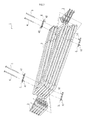
- a heat exchanger 1 includes a plurality of heat-transfer pipes (hereinafter, simply referred to as "pipes") 2. Each of these pipes 2 is shaped so as to surround a predetermined space, and spaced out from each other so that a space for air passage is formed around each of these pipes 2.
- these pipes 2 are arranged in parallel to each other and shaped so as to helically surround a rectangular parallelepiped.
- a pipe group constituted from a plurality of pipe arrays stacked in an up and down direction in the figure is formed around the space.
- the plurality of pipe arrays are constituted from the plurality of pipes 2 arranged along a plurality of planes which cross the stacking direction of the pipe arrays.
- spacers 3 are interposed between the respective adjacent pipe arrays.
- the spacers 3 maintain intervals between the adjacent pipe arrays and intervals between the pipes 2 in the respective pipe arrays.
- each of the spacers 3 includes a plane portion 33 and a plurality of positioning portions 31 which protrude from the plane portion 33.
- the spacer 3 is a plate-like member shaped into a triangular plane, which includes a bent portion 35 and a convex portion 37.
- the bent portion 35 is formed by bending a section extending from one side of the member.
- the convex portion 37 is formed along two sides other than the one side forming the bent portion 35.
- the convex portion 37 protrudes from one surface of the spacer 3 facing upward (hereinafter, referred to as a "first surface”) in a state that the spacer 3 is interposed between the pipe arrays, and the bent portion 35 is bent toward the other surface facing downward (hereinafter, referred to as a "second surface").
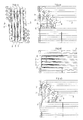
- the positioning portions 31 position the respective pipes 2 located along the second surface of the spacer 3 interposed between the pipe arrays. More particularly, each of the positioning portions 31 protrudes in a direction away from the second surface in one of two spots sandwiching an axis line of each of the pipes 2, thereby to position each of the pipes 2 (see FIGS. 4A to 4D ).
- these positioning portions 31 respectively protrude in the direction of the pipes 2 by denting at least one of two spots sandwiching the axis line of each of the pipes 2 in the plane portion 33 toward the pipes 2.
- side surfaces of the positioning portions 31 slope so as to reduce cross-sectional area of positioning portions 31 toward the protruding direction.
- the positioning portion 31 is in the form of a cone as a whole.
- the six positioning portions 31 are arranged along an outer edge of a triangle according to the shape of the spacer 3. These positioning portions 31 position each of the pipes 2 in at least one of two spots sandwiching the axis line of each of the pipes 2.
- a through hole 39 is formed which penetrates in a thickness direction of the spacers 3.
- the spacers 3, as shown in FIG. 2 are fixed to the pipe group by a pair of clamping members 4 and 5 and bar-like connecting members 6.
- the clamping members 4 and 5 clamp the pipe group in a stacking direction of the pipe arrays.
- the connecting members 6 connect the clamping members 4 and 5.
- the clamping members 4 and 5 are respectively made of a plate-like member extending in a certain direction and having through holes 42 and 52.
- the connecting members 6 reach from the through holes 42 of the one clamping member 4 to the through holes 52 of the other clamping member 5, passing through interspaces between the adjacent pipes 2 in the pipe arrays and the through holes 39 in the spacers 3 sequentially along the stacking direction of the pipe arrays. In this manner, the connecting members 6 connect the pair of clamping members 4 and 5.
- the connecting members 6 are configured as screw members.
- the tip ends of the screw members are fitted into the through holes 52 which are formed as screw holes in the other clamping member 5. In this manner, connection between the clamping member 5 and the connecting members 6 is achieved (see FIGS. 4A to 4D ).
- the two through holes 42 and 52 are formed along a longitudinal direction of the respective clamping members 4 and 5. The connecting members 6 are passed through the respective through holes 42 and 52.
- the pipe group can be fixed by interposing the spacers 3 between the pipe arrays of the pipe group, arranging the pair of clamping members 4 and 5 to sandwich the pipe group, and passing the connecting members 6 through the through holes 42 and 52 of the clamping members 4 and 5, the through holes 39 of the spacers 3, and the interspaces of the adjacent pipes 2 in the respective pipe arrays.
- each of the spacers 3 can maintain the intervals between the pipe arrays by the convex portions 37 of the respective spacers 3, and position the respective pipes 2 in the respective pipe arrays by the positioning portions 31 which protrude from the plane portion 33. In this manner, the spacers 3 can maintain the intervals between the respective pipes 2.
- the spacers 3 are slightly moved in a direction crossing the planes of the pipe arrays by tightening upon fixing the pipe group.
- the pipes 2 are slightly moved along the planes of the pipe arrays along sloped surfaces of the side surfaces of the positioning portions 31.
- the pipes 2 can be fixed without backlash.
- the positioning portions 31 can be easily formed by denting the plane portion 33.
- the spacer 3 which is able to maintain the respective intervals of the pipes 2 can be easily formed from a mere plate-like member.
- a part of the through holes 39 formed in the positioning portions 31 can be used for fixing the spacer 3 and the pipe group.
- the through holes 39 which are not used for fixing the spacer 3 and the pipe group can pass fluid such as ambient air and moisture. Therefore, it is advantageous to restrict retention of the fluid.
- the positioning portions 31 are formed to protrude from the surface side facing upward toward the surface side facing downward when the spacer 3 is interposed between the pipe arrays.
- the pipes 2 can be positioned which are located below the spacer 3.
- the through holes 39 are positioned at the lower ends of the positioning portions 31. Therefore, moisture (so-called drain) which is retained inside dents of the positioning portions 31 can be discharged downward through the through holes 39.
- bending strength of the spacer 3 can be improved by bending part of the end portion of the spacer 3 (the bent portion 35 and the convex portion 37).
- the spacer 3 is applied to the pipe group in the heat exchanger 1.
- the spacer 3 can be applied to a pipe group provided in apparatus other than the heat exchanger 1.
- a fixing structure constituted from the spacers 3, the clamping members 4 and 5 and the connecting members 6 is used for fixation of the pipe group in the heat exchanger 1.
- the fixing structure may be used for fixation of a pipe group provided in apparatus other than the heat exchanger 1.
- the positioning portion 31 of the spacer 3 is formed by denting the plane portion 33 so as to protrude in the dented direction.
- the positioning portion 31 only has to protrude from the plane portion 33.
- the positioning portion 31 may be formed by a member attached to the plane portion 33 or a member formed by cutting and raising the plane portion 33. In this case, the positioning portion 31 is only required to protrude to such an extent that at least part of the positioning portion 31 comes into contact with the pipe 2.
- the positioning portion 31 of the spacer 3 protrudes from the first surface facing upward toward the second surface facing downward.
- the positioning portion 31 may be formed to protrude from the second surface side toward the first surface side.
- the positioning portion 31 may be formed to protrude from both the first surface and the second surface.
- the bent portion 35 of the spacer 3 is bent in the same direction as the direction in which the positioning portion 31 protrudes.
- the bent portion 35 may be bent in the opposite direction to the direction in which the positioning portion 31 protrudes.
- the convex portion 37 of the spacer 3 protrudes in the opposite direction to the direction to which the positioning portion 31 protrudes.
- the convex portion 37 may protrude in the same direction as the direction to which the positioning portion 31 protrudes.
- planar shape of the spacer 3 is formed into an almost triangle.
- the planar shape of the spacer 3 is not limited to a triangle but may be a trapezoid, a rectangle or a circle.
- the pipes 2 are shaped to helically surround a rectangular parallelepiped.
- the pipes 2 may be shaped so as to reciprocate within a predetermined space.
Landscapes
- Engineering & Computer Science (AREA)
- Physics & Mathematics (AREA)
- Thermal Sciences (AREA)
- Mechanical Engineering (AREA)
- General Engineering & Computer Science (AREA)
- Heat-Exchange Devices With Radiators And Conduit Assemblies (AREA)
- Supports For Pipes And Cables (AREA)
Applications Claiming Priority (1)
| Application Number | Priority Date | Filing Date | Title |
|---|---|---|---|
| JP2009151220A JP4963126B2 (ja) | 2009-06-25 | 2009-06-25 | スペーサ、固定部材および熱交換器 |
Publications (3)
| Publication Number | Publication Date |
|---|---|
| EP2278253A2 true EP2278253A2 (fr) | 2011-01-26 |
| EP2278253A3 EP2278253A3 (fr) | 2011-05-11 |
| EP2278253B1 EP2278253B1 (fr) | 2016-09-14 |
Family
ID=42941977
Family Applications (1)
| Application Number | Title | Priority Date | Filing Date |
|---|---|---|---|
| EP10167210.3A Active EP2278253B1 (fr) | 2009-06-25 | 2010-06-24 | Espaceur, structure de fixation et échangeur de chaleur |
Country Status (4)
| Country | Link |
|---|---|
| US (1) | US20100326639A1 (fr) |
| EP (1) | EP2278253B1 (fr) |
| JP (1) | JP4963126B2 (fr) |
| AU (1) | AU2010202577B2 (fr) |
Cited By (3)
| Publication number | Priority date | Publication date | Assignee | Title |
|---|---|---|---|---|
| EP2295914A3 (fr) * | 2009-08-20 | 2011-11-30 | Paloma Co., Ltd. | Échangeur de chaleur de tubes avec des éléments de guidage |
| EP2295913A3 (fr) * | 2009-08-20 | 2011-12-07 | Paloma Co., Ltd. | Échangeur de chaleur à tubes spirales avec des sections penchés |
| WO2017177925A1 (fr) * | 2016-04-15 | 2017-10-19 | 周哲明 | Plaque de refroidissement d'eau composée de multiples canaux |
Families Citing this family (8)
| Publication number | Priority date | Publication date | Assignee | Title |
|---|---|---|---|---|
| US9791221B1 (en) * | 2012-10-30 | 2017-10-17 | Whirlpool Corporation | Condenser assembly system for an appliance |
| US20140262167A1 (en) * | 2013-03-14 | 2014-09-18 | Mao-Ho Kuo | Coil assembly |
| JP6173797B2 (ja) * | 2013-07-01 | 2017-08-02 | 株式会社パロマ | 熱交換器、及び給湯器 |
| JP6173801B2 (ja) * | 2013-07-04 | 2017-08-02 | 株式会社パロマ | 熱交換器及びそれを用いた給湯器 |
| JP6173802B2 (ja) * | 2013-07-04 | 2017-08-02 | 株式会社パロマ | 熱交換器及びそれを用いた給湯器 |
| US10578365B2 (en) | 2016-01-25 | 2020-03-03 | Hiroshi Hatamoto | Heat exchanging apparatus |
| JP7082887B2 (ja) * | 2018-03-13 | 2022-06-09 | 株式会社長府製作所 | 熱交換器及び給湯装置 |
| JP6902582B2 (ja) * | 2019-09-06 | 2021-07-14 | 浩 畑元 | 熱交換装置 |
Citations (1)
| Publication number | Priority date | Publication date | Assignee | Title |
|---|---|---|---|---|
| JP2008151473A (ja) | 2006-12-20 | 2008-07-03 | Noritz Corp | 熱交換器および温水装置 |
Family Cites Families (18)
| Publication number | Priority date | Publication date | Assignee | Title |
|---|---|---|---|---|
| US3055398A (en) * | 1960-05-12 | 1962-09-25 | Tunnessen S Radiator Shop | Spacer |
| FR1473989A (fr) * | 1966-01-12 | 1967-03-24 | Stein Et Roubaix Sa | Dispositif de supportage de panneaux de tubes en serpentin |
| US3822903A (en) * | 1972-03-31 | 1974-07-09 | Mac Kenhus Corp | Multi-core underground conduit-manhole system |
| DE2251866A1 (de) * | 1972-10-23 | 1974-04-25 | Balcke Maschbau Ag | Vorrichtung zur halterung und distanzierung von rohren in einem waermetauscher |
| DE2324386C2 (de) * | 1973-05-14 | 1975-07-03 | Boehringer Mannheim Gmbh, 6800 Mannheim | Wäßriger Cholestrin-Standard |
| GB1463503A (en) * | 1973-10-27 | 1977-02-02 | Simon Eng Dudley Ltd | Access equipment |
| JPS5275823A (en) * | 1975-12-22 | 1977-06-25 | Nippon Kouatsu Concrete | Concrete or mortar portion material |
| JPS62118972U (fr) * | 1986-01-13 | 1987-07-28 | ||
| JP2773936B2 (ja) * | 1989-11-17 | 1998-07-09 | 株式会社日立製作所 | 小口径配管の支持装置 |
| US5213155A (en) * | 1992-04-23 | 1993-05-25 | The Atlantic Group, Inc. | Method and apparatus for multiple locking a single row of heat exchanger tubes |
| JP3287711B2 (ja) * | 1994-11-17 | 2002-06-04 | 古河電気工業株式会社 | 可撓管の並列保持具 |
| JPH08154323A (ja) * | 1994-11-29 | 1996-06-11 | Nippon Tsushin Denzai Kk | 複数管積層用スペーサ |
| US6059025A (en) * | 1998-03-05 | 2000-05-09 | Monsanto Enviro-Chem Systems, Inc. | Heat exchanger configuration |
| US6474613B2 (en) * | 1999-06-11 | 2002-11-05 | O'malley Joseph | High storage density roll stock stacking support |
| US7032655B2 (en) * | 2003-06-24 | 2006-04-25 | Exxonmobil Research & Engineering Company | Anti-vibration tube support |
| US7699093B2 (en) * | 2005-10-20 | 2010-04-20 | Exxonmobil Research And Engineering Company | Anti-vibration tube support for tube bundles having U-shaped bends |
| US7464671B2 (en) * | 2006-07-17 | 2008-12-16 | Babcock & Wilcox Power Generation Group, Inc. | Heat exchanger framework |
| KR101500786B1 (ko) * | 2007-09-11 | 2015-03-09 | 베헤르 게엠베하 운트 콤파니 카게 | 자동차용 열교환기 |
-
2009
- 2009-06-25 JP JP2009151220A patent/JP4963126B2/ja active Active
-
2010
- 2010-06-21 AU AU2010202577A patent/AU2010202577B2/en active Active
- 2010-06-24 EP EP10167210.3A patent/EP2278253B1/fr active Active
- 2010-06-25 US US12/823,161 patent/US20100326639A1/en not_active Abandoned
Patent Citations (1)
| Publication number | Priority date | Publication date | Assignee | Title |
|---|---|---|---|---|
| JP2008151473A (ja) | 2006-12-20 | 2008-07-03 | Noritz Corp | 熱交換器および温水装置 |
Cited By (3)
| Publication number | Priority date | Publication date | Assignee | Title |
|---|---|---|---|---|
| EP2295914A3 (fr) * | 2009-08-20 | 2011-11-30 | Paloma Co., Ltd. | Échangeur de chaleur de tubes avec des éléments de guidage |
| EP2295913A3 (fr) * | 2009-08-20 | 2011-12-07 | Paloma Co., Ltd. | Échangeur de chaleur à tubes spirales avec des sections penchés |
| WO2017177925A1 (fr) * | 2016-04-15 | 2017-10-19 | 周哲明 | Plaque de refroidissement d'eau composée de multiples canaux |
Also Published As
| Publication number | Publication date |
|---|---|
| US20100326639A1 (en) | 2010-12-30 |
| AU2010202577A1 (en) | 2011-01-20 |
| JP2011007420A (ja) | 2011-01-13 |
| EP2278253B1 (fr) | 2016-09-14 |
| AU2010202577B2 (en) | 2015-02-19 |
| JP4963126B2 (ja) | 2012-06-27 |
| EP2278253A3 (fr) | 2011-05-11 |
Similar Documents
| Publication | Publication Date | Title |
|---|---|---|
| EP2278253A2 (fr) | Espaceur, structure de fixation et échangeur de chaleur | |
| KR102291431B1 (ko) | 열 교환 판 및 열 교환 판을 구비한 판형 열 교환기 | |
| JP6892920B2 (ja) | 冷却プレート | |
| US20200191494A1 (en) | Cooling device with superimposed fin groups | |
| KR102590069B1 (ko) | 열 교환기용 핀 조립체 및 그러한 핀 조립체를 가지는 열 교환기 | |
| US11867467B2 (en) | Cooling device with superimposed fin groups | |
| JP4388994B1 (ja) | 熱交換器 | |
| JP5952259B2 (ja) | 熱交換器 | |
| JP6233540B2 (ja) | 熱交換器及び空調機 | |
| JP2018521293A5 (fr) | ||
| JP2004184075A (ja) | 伝熱プレート及びプレート式熱交換器 | |
| US20180172356A1 (en) | Profiled joint for heat exchanger | |
| RU2666262C2 (ru) | Теплообменное устройство с окружным уплотнительным элементом | |
| US7137440B2 (en) | Heat sink for electronic device | |
| AU2010212318B2 (en) | Heat Exchanger | |
| JP2017133790A (ja) | 熱交換器 | |
| KR20110083016A (ko) | 열 교환기용 핀 및 이를 갖는 열 교환기 | |
| WO2015040746A1 (fr) | Échangeur de chaleur ainsi que procédé de fabrication de celui-ci, et dispositif de conditionnement d'air équipé de celui-ci | |
| JP5920132B2 (ja) | 熱交換器のブラケット取付装置 | |
| JP2018017488A (ja) | コアサポート | |
| KR20180001748A (ko) | 다단구조를 포함하는 용접지그 | |
| EP3287731A1 (fr) | Plaque d'échangeur de chaleur et échangeur de chaleur à plaques | |
| JP5861556B2 (ja) | 床暖房配管接続構造 | |
| KR20110085772A (ko) | 열 교환기용 핀 및 이를 갖는 열 교환기 | |
| KR102581885B1 (ko) | 열교환기 |
Legal Events
| Date | Code | Title | Description |
|---|---|---|---|
| PUAI | Public reference made under article 153(3) epc to a published international application that has entered the european phase |
Free format text: ORIGINAL CODE: 0009012 |
|
| AK | Designated contracting states |
Kind code of ref document: A2 Designated state(s): AL AT BE BG CH CY CZ DE DK EE ES FI FR GB GR HR HU IE IS IT LI LT LU LV MC MK MT NL NO PL PT RO SE SI SK SM TR |
|
| AX | Request for extension of the european patent |
Extension state: BA ME RS |
|
| PUAL | Search report despatched |
Free format text: ORIGINAL CODE: 0009013 |
|
| AK | Designated contracting states |
Kind code of ref document: A3 Designated state(s): AL AT BE BG CH CY CZ DE DK EE ES FI FR GB GR HR HU IE IS IT LI LT LU LV MC MK MT NL NO PL PT RO SE SI SK SM TR |
|
| AX | Request for extension of the european patent |
Extension state: BA ME RS |
|
| RIC1 | Information provided on ipc code assigned before grant |
Ipc: F28D 1/047 20060101ALI20110406BHEP Ipc: F28F 9/013 20060101AFI20101020BHEP Ipc: F28D 7/02 20060101ALI20110406BHEP |
|
| RAP1 | Party data changed (applicant data changed or rights of an application transferred) |
Owner name: PALOMA CO., LTD. |
|
| 17P | Request for examination filed |
Effective date: 20111109 |
|
| 17Q | First examination report despatched |
Effective date: 20130723 |
|
| GRAP | Despatch of communication of intention to grant a patent |
Free format text: ORIGINAL CODE: EPIDOSNIGR1 |
|
| RIN1 | Information on inventor provided before grant (corrected) |
Inventor name: ANDO, YOSHIO |
|
| INTG | Intention to grant announced |
Effective date: 20160609 |
|
| RAP1 | Party data changed (applicant data changed or rights of an application transferred) |
Owner name: PALOMA CO., LTD. |
|
| GRAS | Grant fee paid |
Free format text: ORIGINAL CODE: EPIDOSNIGR3 |
|
| GRAA | (expected) grant |
Free format text: ORIGINAL CODE: 0009210 |
|
| AK | Designated contracting states |
Kind code of ref document: B1 Designated state(s): AL AT BE BG CH CY CZ DE DK EE ES FI FR GB GR HR HU IE IS IT LI LT LU LV MC MK MT NL NO PL PT RO SE SI SK SM TR |
|
| REG | Reference to a national code |
Ref country code: GB Ref legal event code: FG4D |
|
| REG | Reference to a national code |
Ref country code: CH Ref legal event code: EP |
|
| REG | Reference to a national code |
Ref country code: IE Ref legal event code: FG4D |
|
| REG | Reference to a national code |
Ref country code: AT Ref legal event code: REF Ref document number: 829474 Country of ref document: AT Kind code of ref document: T Effective date: 20161015 |
|
| REG | Reference to a national code |
Ref country code: DE Ref legal event code: R096 Ref document number: 602010036362 Country of ref document: DE |
|
| REG | Reference to a national code |
Ref country code: LT Ref legal event code: MG4D |
|
| REG | Reference to a national code |
Ref country code: NL Ref legal event code: MP Effective date: 20160914 |
|
| PG25 | Lapsed in a contracting state [announced via postgrant information from national office to epo] |
Ref country code: LT Free format text: LAPSE BECAUSE OF FAILURE TO SUBMIT A TRANSLATION OF THE DESCRIPTION OR TO PAY THE FEE WITHIN THE PRESCRIBED TIME-LIMIT Effective date: 20160914 Ref country code: NO Free format text: LAPSE BECAUSE OF FAILURE TO SUBMIT A TRANSLATION OF THE DESCRIPTION OR TO PAY THE FEE WITHIN THE PRESCRIBED TIME-LIMIT Effective date: 20161214 Ref country code: FI Free format text: LAPSE BECAUSE OF FAILURE TO SUBMIT A TRANSLATION OF THE DESCRIPTION OR TO PAY THE FEE WITHIN THE PRESCRIBED TIME-LIMIT Effective date: 20160914 Ref country code: HR Free format text: LAPSE BECAUSE OF FAILURE TO SUBMIT A TRANSLATION OF THE DESCRIPTION OR TO PAY THE FEE WITHIN THE PRESCRIBED TIME-LIMIT Effective date: 20160914 |
|
| REG | Reference to a national code |
Ref country code: AT Ref legal event code: MK05 Ref document number: 829474 Country of ref document: AT Kind code of ref document: T Effective date: 20160914 |
|
| PG25 | Lapsed in a contracting state [announced via postgrant information from national office to epo] |
Ref country code: ES Free format text: LAPSE BECAUSE OF FAILURE TO SUBMIT A TRANSLATION OF THE DESCRIPTION OR TO PAY THE FEE WITHIN THE PRESCRIBED TIME-LIMIT Effective date: 20160914 Ref country code: GR Free format text: LAPSE BECAUSE OF FAILURE TO SUBMIT A TRANSLATION OF THE DESCRIPTION OR TO PAY THE FEE WITHIN THE PRESCRIBED TIME-LIMIT Effective date: 20161215 Ref country code: LV Free format text: LAPSE BECAUSE OF FAILURE TO SUBMIT A TRANSLATION OF THE DESCRIPTION OR TO PAY THE FEE WITHIN THE PRESCRIBED TIME-LIMIT Effective date: 20160914 Ref country code: SE Free format text: LAPSE BECAUSE OF FAILURE TO SUBMIT A TRANSLATION OF THE DESCRIPTION OR TO PAY THE FEE WITHIN THE PRESCRIBED TIME-LIMIT Effective date: 20160914 Ref country code: NL Free format text: LAPSE BECAUSE OF FAILURE TO SUBMIT A TRANSLATION OF THE DESCRIPTION OR TO PAY THE FEE WITHIN THE PRESCRIBED TIME-LIMIT Effective date: 20160914 |
|
| PG25 | Lapsed in a contracting state [announced via postgrant information from national office to epo] |
Ref country code: EE Free format text: LAPSE BECAUSE OF FAILURE TO SUBMIT A TRANSLATION OF THE DESCRIPTION OR TO PAY THE FEE WITHIN THE PRESCRIBED TIME-LIMIT Effective date: 20160914 Ref country code: RO Free format text: LAPSE BECAUSE OF FAILURE TO SUBMIT A TRANSLATION OF THE DESCRIPTION OR TO PAY THE FEE WITHIN THE PRESCRIBED TIME-LIMIT Effective date: 20160914 |
|
| REG | Reference to a national code |
Ref country code: FR Ref legal event code: PLFP Year of fee payment: 8 |
|
| PG25 | Lapsed in a contracting state [announced via postgrant information from national office to epo] |
Ref country code: SK Free format text: LAPSE BECAUSE OF FAILURE TO SUBMIT A TRANSLATION OF THE DESCRIPTION OR TO PAY THE FEE WITHIN THE PRESCRIBED TIME-LIMIT Effective date: 20160914 Ref country code: CZ Free format text: LAPSE BECAUSE OF FAILURE TO SUBMIT A TRANSLATION OF THE DESCRIPTION OR TO PAY THE FEE WITHIN THE PRESCRIBED TIME-LIMIT Effective date: 20160914 Ref country code: BG Free format text: LAPSE BECAUSE OF FAILURE TO SUBMIT A TRANSLATION OF THE DESCRIPTION OR TO PAY THE FEE WITHIN THE PRESCRIBED TIME-LIMIT Effective date: 20161214 Ref country code: PT Free format text: LAPSE BECAUSE OF FAILURE TO SUBMIT A TRANSLATION OF THE DESCRIPTION OR TO PAY THE FEE WITHIN THE PRESCRIBED TIME-LIMIT Effective date: 20170116 Ref country code: IS Free format text: LAPSE BECAUSE OF FAILURE TO SUBMIT A TRANSLATION OF THE DESCRIPTION OR TO PAY THE FEE WITHIN THE PRESCRIBED TIME-LIMIT Effective date: 20170114 Ref country code: SM Free format text: LAPSE BECAUSE OF FAILURE TO SUBMIT A TRANSLATION OF THE DESCRIPTION OR TO PAY THE FEE WITHIN THE PRESCRIBED TIME-LIMIT Effective date: 20160914 Ref country code: PL Free format text: LAPSE BECAUSE OF FAILURE TO SUBMIT A TRANSLATION OF THE DESCRIPTION OR TO PAY THE FEE WITHIN THE PRESCRIBED TIME-LIMIT Effective date: 20160914 Ref country code: BE Free format text: LAPSE BECAUSE OF FAILURE TO SUBMIT A TRANSLATION OF THE DESCRIPTION OR TO PAY THE FEE WITHIN THE PRESCRIBED TIME-LIMIT Effective date: 20160914 Ref country code: AT Free format text: LAPSE BECAUSE OF FAILURE TO SUBMIT A TRANSLATION OF THE DESCRIPTION OR TO PAY THE FEE WITHIN THE PRESCRIBED TIME-LIMIT Effective date: 20160914 |
|
| REG | Reference to a national code |
Ref country code: DE Ref legal event code: R097 Ref document number: 602010036362 Country of ref document: DE |
|
| PG25 | Lapsed in a contracting state [announced via postgrant information from national office to epo] |
Ref country code: IT Free format text: LAPSE BECAUSE OF FAILURE TO SUBMIT A TRANSLATION OF THE DESCRIPTION OR TO PAY THE FEE WITHIN THE PRESCRIBED TIME-LIMIT Effective date: 20160914 |
|
| PLBE | No opposition filed within time limit |
Free format text: ORIGINAL CODE: 0009261 |
|
| STAA | Information on the status of an ep patent application or granted ep patent |
Free format text: STATUS: NO OPPOSITION FILED WITHIN TIME LIMIT |
|
| PG25 | Lapsed in a contracting state [announced via postgrant information from national office to epo] |
Ref country code: DK Free format text: LAPSE BECAUSE OF FAILURE TO SUBMIT A TRANSLATION OF THE DESCRIPTION OR TO PAY THE FEE WITHIN THE PRESCRIBED TIME-LIMIT Effective date: 20160914 |
|
| 26N | No opposition filed |
Effective date: 20170615 |
|
| PG25 | Lapsed in a contracting state [announced via postgrant information from national office to epo] |
Ref country code: SI Free format text: LAPSE BECAUSE OF FAILURE TO SUBMIT A TRANSLATION OF THE DESCRIPTION OR TO PAY THE FEE WITHIN THE PRESCRIBED TIME-LIMIT Effective date: 20160914 |
|
| PG25 | Lapsed in a contracting state [announced via postgrant information from national office to epo] |
Ref country code: MC Free format text: LAPSE BECAUSE OF FAILURE TO SUBMIT A TRANSLATION OF THE DESCRIPTION OR TO PAY THE FEE WITHIN THE PRESCRIBED TIME-LIMIT Effective date: 20160914 |
|
| REG | Reference to a national code |
Ref country code: CH Ref legal event code: PL |
|
| REG | Reference to a national code |
Ref country code: IE Ref legal event code: MM4A |
|
| PG25 | Lapsed in a contracting state [announced via postgrant information from national office to epo] |
Ref country code: LI Free format text: LAPSE BECAUSE OF NON-PAYMENT OF DUE FEES Effective date: 20170630 Ref country code: IE Free format text: LAPSE BECAUSE OF NON-PAYMENT OF DUE FEES Effective date: 20170624 Ref country code: LU Free format text: LAPSE BECAUSE OF NON-PAYMENT OF DUE FEES Effective date: 20170624 Ref country code: CH Free format text: LAPSE BECAUSE OF NON-PAYMENT OF DUE FEES Effective date: 20170630 |
|
| REG | Reference to a national code |
Ref country code: FR Ref legal event code: PLFP Year of fee payment: 9 |
|
| PG25 | Lapsed in a contracting state [announced via postgrant information from national office to epo] |
Ref country code: MT Free format text: LAPSE BECAUSE OF NON-PAYMENT OF DUE FEES Effective date: 20170624 |
|
| PG25 | Lapsed in a contracting state [announced via postgrant information from national office to epo] |
Ref country code: AL Free format text: LAPSE BECAUSE OF FAILURE TO SUBMIT A TRANSLATION OF THE DESCRIPTION OR TO PAY THE FEE WITHIN THE PRESCRIBED TIME-LIMIT Effective date: 20160914 |
|
| PG25 | Lapsed in a contracting state [announced via postgrant information from national office to epo] |
Ref country code: HU Free format text: LAPSE BECAUSE OF FAILURE TO SUBMIT A TRANSLATION OF THE DESCRIPTION OR TO PAY THE FEE WITHIN THE PRESCRIBED TIME-LIMIT; INVALID AB INITIO Effective date: 20100624 |
|
| PG25 | Lapsed in a contracting state [announced via postgrant information from national office to epo] |
Ref country code: CY Free format text: LAPSE BECAUSE OF NON-PAYMENT OF DUE FEES Effective date: 20160914 |
|
| PG25 | Lapsed in a contracting state [announced via postgrant information from national office to epo] |
Ref country code: MK Free format text: LAPSE BECAUSE OF FAILURE TO SUBMIT A TRANSLATION OF THE DESCRIPTION OR TO PAY THE FEE WITHIN THE PRESCRIBED TIME-LIMIT Effective date: 20160914 |
|
| PG25 | Lapsed in a contracting state [announced via postgrant information from national office to epo] |
Ref country code: TR Free format text: LAPSE BECAUSE OF FAILURE TO SUBMIT A TRANSLATION OF THE DESCRIPTION OR TO PAY THE FEE WITHIN THE PRESCRIBED TIME-LIMIT Effective date: 20160914 |
|
| REG | Reference to a national code |
Ref country code: DE Ref legal event code: R082 Ref document number: 602010036362 Country of ref document: DE Representative=s name: PRUEFER & PARTNER MBB PATENTANWAELTE RECHTSANW, DE Ref country code: DE Ref legal event code: R081 Ref document number: 602010036362 Country of ref document: DE Owner name: PALOMA RHEEM HOLDINGS CO., LTD., JP Free format text: FORMER OWNER: PALOMA CO., LTD., NAGOYA-SHI, AICHI, JP |
|
| PGFP | Annual fee paid to national office [announced via postgrant information from national office to epo] |
Ref country code: DE Payment date: 20250429 Year of fee payment: 16 |
|
| PGFP | Annual fee paid to national office [announced via postgrant information from national office to epo] |
Ref country code: GB Payment date: 20250501 Year of fee payment: 16 |
|
| PGFP | Annual fee paid to national office [announced via postgrant information from national office to epo] |
Ref country code: FR Payment date: 20250508 Year of fee payment: 16 |