EP2278376A2 - Mircroscope chirurgical avec deux dispositifs d'éclairage - Google Patents
Mircroscope chirurgical avec deux dispositifs d'éclairage Download PDFInfo
- Publication number
- EP2278376A2 EP2278376A2 EP10186203A EP10186203A EP2278376A2 EP 2278376 A2 EP2278376 A2 EP 2278376A2 EP 10186203 A EP10186203 A EP 10186203A EP 10186203 A EP10186203 A EP 10186203A EP 2278376 A2 EP2278376 A2 EP 2278376A2
- Authority
- EP
- European Patent Office
- Prior art keywords
- illumination
- excitation
- beam path
- light
- filter
- Prior art date
- Legal status (The legal status is an assumption and is not a legal conclusion. Google has not performed a legal analysis and makes no representation as to the accuracy of the status listed.)
- Withdrawn
Links
- 238000005286 illumination Methods 0.000 title claims abstract description 90
- 230000005284 excitation Effects 0.000 claims abstract description 37
- 230000003287 optical effect Effects 0.000 claims abstract description 29
- 230000003595 spectral effect Effects 0.000 claims description 24
- 230000007257 malfunction Effects 0.000 claims description 2
- 229910052724 xenon Inorganic materials 0.000 abstract description 4
- FHNFHKCVQCLJFQ-UHFFFAOYSA-N xenon atom Chemical compound [Xe] FHNFHKCVQCLJFQ-UHFFFAOYSA-N 0.000 abstract description 4
- QSHDDOUJBYECFT-UHFFFAOYSA-N mercury Chemical compound [Hg] QSHDDOUJBYECFT-UHFFFAOYSA-N 0.000 abstract description 2
- 239000013307 optical fiber Substances 0.000 description 8
- 239000000835 fiber Substances 0.000 description 3
- ZGXJTSGNIOSYLO-UHFFFAOYSA-N 88755TAZ87 Chemical compound NCC(=O)CCC(O)=O ZGXJTSGNIOSYLO-UHFFFAOYSA-N 0.000 description 2
- 229960002749 aminolevulinic acid Drugs 0.000 description 2
- 230000000694 effects Effects 0.000 description 2
- 238000000695 excitation spectrum Methods 0.000 description 2
- 238000000034 method Methods 0.000 description 2
- 238000001228 spectrum Methods 0.000 description 2
- 230000001360 synchronised effect Effects 0.000 description 2
- LYPFDBRUNKHDGX-UHFFFAOYSA-N temoporfin Chemical compound OC1=CC=CC(C=2C3=CC=C(N3)C(C=3C=C(O)C=CC=3)=C3C=CC(=N3)C(C=3C=C(O)C=CC=3)=C3C=CC(N3)=C(C=3C=C(O)C=CC=3)C=3CCC=2N=3)=C1 LYPFDBRUNKHDGX-UHFFFAOYSA-N 0.000 description 2
- 241001295925 Gegenes Species 0.000 description 1
- 206010028980 Neoplasm Diseases 0.000 description 1
- 238000002583 angiography Methods 0.000 description 1
- 238000010276 construction Methods 0.000 description 1
- 230000001419 dependent effect Effects 0.000 description 1
- 230000001627 detrimental effect Effects 0.000 description 1
- 229940079593 drug Drugs 0.000 description 1
- 239000003814 drug Substances 0.000 description 1
- 230000005670 electromagnetic radiation Effects 0.000 description 1
- 238000001914 filtration Methods 0.000 description 1
- 238000012806 monitoring device Methods 0.000 description 1
- 238000005457 optimization Methods 0.000 description 1
- 230000001151 other effect Effects 0.000 description 1
- 239000000126 substance Substances 0.000 description 1
- 238000011477 surgical intervention Methods 0.000 description 1
Images


Classifications
-
- G—PHYSICS
- G02—OPTICS
- G02B—OPTICAL ELEMENTS, SYSTEMS OR APPARATUS
- G02B21/00—Microscopes
- G02B21/18—Arrangements with more than one light path, e.g. for comparing two specimens
- G02B21/20—Binocular arrangements
- G02B21/22—Stereoscopic arrangements
-
- A—HUMAN NECESSITIES
- A61—MEDICAL OR VETERINARY SCIENCE; HYGIENE
- A61B—DIAGNOSIS; SURGERY; IDENTIFICATION
- A61B90/00—Instruments, implements or accessories specially adapted for surgery or diagnosis and not covered by any of the groups A61B1/00 - A61B50/00, e.g. for luxation treatment or for protecting wound edges
- A61B90/36—Image-producing devices or illumination devices not otherwise provided for
-
- G—PHYSICS
- G02—OPTICS
- G02B—OPTICAL ELEMENTS, SYSTEMS OR APPARATUS
- G02B21/00—Microscopes
- G02B21/0004—Microscopes specially adapted for specific applications
- G02B21/0012—Surgical microscopes
-
- G—PHYSICS
- G02—OPTICS
- G02B—OPTICAL ELEMENTS, SYSTEMS OR APPARATUS
- G02B21/00—Microscopes
- G02B21/06—Means for illuminating specimens
- G02B21/08—Condensers
- G02B21/082—Condensers for incident illumination only
-
- A—HUMAN NECESSITIES
- A61—MEDICAL OR VETERINARY SCIENCE; HYGIENE
- A61B—DIAGNOSIS; SURGERY; IDENTIFICATION
- A61B90/00—Instruments, implements or accessories specially adapted for surgery or diagnosis and not covered by any of the groups A61B1/00 - A61B50/00, e.g. for luxation treatment or for protecting wound edges
- A61B90/20—Surgical microscopes characterised by non-optical aspects
-
- A—HUMAN NECESSITIES
- A61—MEDICAL OR VETERINARY SCIENCE; HYGIENE
- A61B—DIAGNOSIS; SURGERY; IDENTIFICATION
- A61B90/00—Instruments, implements or accessories specially adapted for surgery or diagnosis and not covered by any of the groups A61B1/00 - A61B50/00, e.g. for luxation treatment or for protecting wound edges
- A61B90/30—Devices for illuminating a surgical field, the devices having an interrelation with other surgical devices or with a surgical procedure
Definitions
- the invention relates to an operation stereomicroscope with fluorescence mode of operation with an illumination source whose light predetermined spectral range (white light) can be directed by means of an optical device against an object to be observed.
- the light of at least one further illumination in a different spectral range is switchable.
- Fluorescence is a well-known method which uses a matched filter to apply a defined excitation spectrum to an object and spectrally separate the signal response emitted by the object from the excitation light for observation and analysis.
- many applications are known which support surgical interventions and mark the tissue to be resected via the emitted fluorescence.
- a particular example of the use of such a method with fluorescence devices integrated into a microscope are surgical microscopes for neurosurgery using photodynamic drugs containing e.g.
- ALA Amino Levulinic Acid
- mTHPC Meso-Tetra-Hydroxy-Phenyl-Chlorin
- infrared angiography in which light from the NIR (near infrared) region is used for excitation, in order then to observe the object in the longer wavelength spectral range.
- NIR near infrared
- Other applications use ultraviolet (not visible).
- Other spectral ranges between ultraviolet to blue light and from there to red and far infrared are also possible.
- the sufficient intensity of the excitation spectrum is of essential importance.
- a specific fluorescence signal (for example at ALA 635 nm) will be obtained, depending on the fluorescent substance used.
- xenon light sources of 300 W are generally used, which provide both the normal microscopic white light, as well as the need for fluorescence blue light, namely the latter by filtering and optimization of the spectral range of 380-420 nm by targeted selection of the xenon burner.
- microscopes or surgical microscopes can be found approximately in the US-A-6,510,338 or the DE-A-195 48 913 , There, the light of the illumination device is supplied via optical fibers and other optical devices to the object to be observed.
- a problem with these known microscopes is that a compromise has to be made in the selection of the illumination source, which ultimately leads to the fact that the white light quality for the observation can not be optimized, on the other hand, other spectral regions are represented disproportionately even with increased and optimized blue light component and then lead to color casts in the standard white light situation. Although a correction of the color cast through filters is theoretically possible, but then leads to a reduction in intensity. On the other hand, a correct color observation of an operating area is important for diagnostic reasons. An increase in intensity is not possible due to the limited aperture of the microscopic illumination optics and other effects of an increase in lamp power.
- the present invention is therefore based on the object, a microscope of the type mentioned in such a way that - despite the given restriction by the aperture of the illumination optics - an increase in intensity of the illumination in both white light operation, as well as in the excitation mode is possible.
- Another object of the invention is to improve the quality of white light.
- the invention proposes that the Optics device is provided with at least one connection for a further illumination source.
- at least one connection should be provided for a further illumination source, whereby it is then readily possible to optimize one illumination source with the predetermined spectral range as a white light source, while the other uses that spectral range which is just required for a particular application is appropriate. It would even be conceivable to arrange a plurality of connections for more than two illumination sources, which can then be brought into effect by appropriate optical and / or electrical switching devices.
- the respective further illumination source into the microscope, wherein the embodiment can be made such that the microscope then contains the at least one further illumination device, and that this further illumination device deviates from the predetermined spectral range has spectral scope.
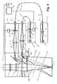
- an object 1 is to be viewed by means of a microscope, which has a schematically indicated microscope body 10 in a known per se construction.
- an optical system for generating an observation beam path 11 is mounted along an optical axis 12 in a manner known per se, which comprises a main objective 13, which is indicated only as a lens.
- an observation device in the widest sense
- an electromechanical movement device 17 such as an electromagnet, a rotor motor or a similar motor (disclosure: Paragraph 16, lines 33-34)
- filters 18 optionally one at the top of the observation beam path 11 (not shown) eyepiece. It is understood that in the case of a stereomicroscope, two such observation beam paths are provided.
- two light or illumination sources 20, 30 are provided, each having an illumination beam path 41 and 51 and a Umlenkspiegel Structure, preferably in the form of a mirror surface on a illumination prism 46 and 56, respectively each throw an illumination beam path 45 or 55 along an associated optical axis 44 or 54 onto the object 1 to be observed.
- the invention makes it possible to optimally adapt the illumination sources to the requirements. For example, for white light (ie for the light source 20) in particular a xenon lamp can be used. For light wavelengths in the range around 400 nm (blue light), a mercury vapor lamp is recommended, and for infrared, the most diverse light sources in question
- Each of these illumination beam paths from the light source 20 or 30 to the object 1 respectively comprises a lighting body 21 or 31, the light (here light is visible and invisible light, ie generally understood electromagnetic radiation) along an optical axis 22 and 32 respectively via an illumination optical system 23 or 33 to the inlet 24 or 34 of an optical waveguide 25 or 35 transmits, which directs the light to a light exit 26 and 36, respectively.
- the optical waveguide 25 or 35 is curved, that is shown as a fiber optic bundle, but the invention is by no means limited thereto, rather, the respective illumination source could be 20 or 30 quite well mounted so that its optical axis 22 and 32 with a on the microscope body 10 continuing optical axis 42 and 52 each of an illumination beam path 41 and 51 coincides.
- optical fibers are within the scope of Invention quite conceivable and possible, although the illustrated embodiment with optical fibers 25 and 35, or at least one of them, is preferred.
- a standard illumination source 20 is already built into the tripod of a surgical microscope.
- the optical fiber outlet 36 needs to be formed only as a connection for a subsequently to be coupled optical waveguide 35. Connections for optical waveguides are known per se, which is why a detailed discussion is omitted here. Expediently, this connection 34 is then attached to a separate illumination module 40, which can be attached to an existing microscope at most, with the corresponding optical parts 43 and 46.
- this converging lens 43 or 53 may be composed of a plurality of individual lenses.
- the two optical axes 42, 52 hit the mirror prisms 46 and 56 to be deflected in the already mentioned illumination beam path 45 and 55 with the optical axes 44 and 54, respectively.
- These illumination beam paths 45, 55 are now located near the observation beam path 11, for which reason a covering light aperture 16 is advantageously provided therebetween.
- one of the illumination sources 20 or 30 is now switched on, eg via a switch 62 connected to a control or monitoring device 60 (hand or foot switch, keypad or voice control, etc.) and via lines 63 and 64, respectively
- a switch 62 connected to a control or monitoring device 60 (hand or foot switch, keypad or voice control, etc.) and via lines 63 and 64, respectively
- object 1 for example with white light or with blue light.
- filters 38 and 58 for the excitation or 18 for the observation are brought into the respective beam path 11, 41 and 51, respectively.
- These are essentially similar electromechanical movement devices 37 and 57, respectively provided as already described above with reference to the device 17.
- All of these devices 17, 37 and 57 are controlled by the control device 60 and the switch 62 via the signal connection 61, 61 ', in such a way that the movement of the excitation filter 38, 58, but advantageously also of the observation filter 18, takes place synchronously.
- the controller may include as hardware or software a limit switch with feedback, which prevents the object is unintentionally illuminated simultaneously with white light and excitation light.
- Fig. 1 What in Fig. 1 is shown as a single filter 38 may (and this also applies to the other filters 18 and 58) comprise a plurality of successively arranged and optionally insertable filter.
- a filter for the white light mode is provided by which the spectrum of the light source 31 is corrected.
- an excitation filter is provided which only pivots in order to allow only the excitation wavelength to pass.
- the illumination energy of both light sources 21 and 31 can then be available with the desired excitation wavelength (with the filter 58 swiveled in), so that the intensity as a whole is increased.
- the switch 62 may also be used to turn off one of the light sources 20 or 30 when additional light is undesirable for an application.
- Filter exchangers with a plurality of filter sets can also be provided for a plurality of different - but also identical, synchronous - excitation and / or observation wavelengths, although the present invention also permits multiple connections (see the connection 36) for a plurality of light sources of different excitation spectral range provided.
- Fig. 2 differs from that of Fig. 1 essentially in that the excitation filter 58 ( Fig. 1 ) is omitted in the microscope body 10 and instead an excitation filter 28 installed in the light source 20 is, so that the electromechanical effort in the microscope body 10 is avoided or reduced. So this is preferred for structural reasons, especially since this embodiment has no detrimental effect on the function.
- the embodiment according to Fig. 3 differs from the previous embodiments by the placement of the filter.
- the output line 61 of the control unit 60 is connected to an electromechanical movement device or a central motor 67 in the microscope body 10, which adjusts a filter set 68 both in the observation beam path 11 and in the illumination beam path 45 or 55 such that at the same time the excitation filter 68a for the first and second light source 20 or 30 in the illumination beam paths 45 and 55 and the observation filter 68b in the observation beam path 11 become effective (or be removed from these beam paths).
- the cost of electromechanical movement devices is significantly reduced in this embodiment, although it must be taken into account that the device in the microscope body 10 must be accommodated. Which of the embodiments is therefore preferred, in particular which of those of Fig. 2 or Fig.
- Fig. 4 shows a combination of the versions Fig. 3 with that of Fig. 1 , It thus makes it possible, if necessary, to bring different illumination or excitation filters 68, 58 and / or 38 into effect, for which purpose the control unit 60 is equipped with corresponding control lines or signal buses 61, 61 '.
- This embodiment can of course be used for a wide variety of applications.
Landscapes
- Physics & Mathematics (AREA)
- Health & Medical Sciences (AREA)
- Surgery (AREA)
- Analytical Chemistry (AREA)
- General Physics & Mathematics (AREA)
- Optics & Photonics (AREA)
- Chemical & Material Sciences (AREA)
- Life Sciences & Earth Sciences (AREA)
- General Health & Medical Sciences (AREA)
- Engineering & Computer Science (AREA)
- Nuclear Medicine, Radiotherapy & Molecular Imaging (AREA)
- Pathology (AREA)
- Biomedical Technology (AREA)
- Heart & Thoracic Surgery (AREA)
- Medical Informatics (AREA)
- Molecular Biology (AREA)
- Animal Behavior & Ethology (AREA)
- Oral & Maxillofacial Surgery (AREA)
- Public Health (AREA)
- Veterinary Medicine (AREA)
- Microscoopes, Condenser (AREA)
Applications Claiming Priority (2)
| Application Number | Priority Date | Filing Date | Title |
|---|---|---|---|
| DE102005005984.8A DE102005005984B4 (de) | 2005-02-09 | 2005-02-09 | Fluoreszenz-/Infraroteinrichtung für Operationsmikroskope |
| EP06100806A EP1691229A1 (fr) | 2005-02-09 | 2006-01-25 | Mircroscope chirurgical avec deux dispositifs d'éclairage |
Related Parent Applications (1)
| Application Number | Title | Priority Date | Filing Date |
|---|---|---|---|
| EP06100806.6 Division | 2006-01-25 |
Publications (2)
| Publication Number | Publication Date |
|---|---|
| EP2278376A2 true EP2278376A2 (fr) | 2011-01-26 |
| EP2278376A3 EP2278376A3 (fr) | 2013-06-26 |
Family
ID=35999440
Family Applications (2)
| Application Number | Title | Priority Date | Filing Date |
|---|---|---|---|
| EP06100806A Ceased EP1691229A1 (fr) | 2005-02-09 | 2006-01-25 | Mircroscope chirurgical avec deux dispositifs d'éclairage |
| EP10186203.5A Withdrawn EP2278376A3 (fr) | 2005-02-09 | 2006-01-25 | Mircroscope chirurgical avec deux dispositifs d'éclairage |
Family Applications Before (1)
| Application Number | Title | Priority Date | Filing Date |
|---|---|---|---|
| EP06100806A Ceased EP1691229A1 (fr) | 2005-02-09 | 2006-01-25 | Mircroscope chirurgical avec deux dispositifs d'éclairage |
Country Status (4)
| Country | Link |
|---|---|
| US (1) | US7649685B2 (fr) |
| EP (2) | EP1691229A1 (fr) |
| JP (1) | JP5022606B2 (fr) |
| DE (1) | DE102005005984B4 (fr) |
Families Citing this family (12)
| Publication number | Priority date | Publication date | Assignee | Title |
|---|---|---|---|---|
| DE102009024942A1 (de) * | 2009-06-09 | 2010-12-23 | Carl Zeiss Surgical Gmbh | Lichtquellenanordnung für eine Beleuchtungsvorrichtung eines medizinisch-optischen Beobachtungsgeräts |
| DE102010044502A1 (de) | 2010-09-06 | 2012-03-08 | Leica Microsystems (Schweiz) Ag | Sonderbeleuchtungs-Video-Operations-Stereomikroskop |
| DE102010044503B4 (de) | 2010-09-06 | 2017-11-02 | Leica Microsystems (Schweiz) Ag | Fluoreszenz-Operations-Stereomikroskop |
| EP2821004B1 (fr) * | 2011-04-18 | 2015-08-05 | Karl Storz GmbH & Co. KG | Exoscope |
| US8810905B2 (en) * | 2012-01-30 | 2014-08-19 | Kenneth W. Bauer | Stereomicroscope fluorescence system |
| DE102012201371A1 (de) | 2012-01-31 | 2013-08-01 | Leica Microsystems (Schweiz) Ag | Multiphotonenfluoroskopievorsatzmodul für ein Operationsmikroskop |
| DE102012001854A1 (de) * | 2012-02-01 | 2013-08-01 | Leica Microsystems (Schweiz) Ag | Sonderbeleuchtungs-Operations-Stereomikroskop |
| WO2013167167A1 (fr) * | 2012-05-07 | 2013-11-14 | Carl Zeiss Industrielle Messtechnik Gmbh | Module d'éclairage remplaçable pour un appareil de mesure de coordonnées |
| DE102013226784A1 (de) * | 2013-12-19 | 2015-06-25 | Leica Microsysteme (Schweiz) AG | Operationsmikroskop |
| DE102015003681B4 (de) | 2015-03-24 | 2023-12-21 | Karl Storz Se & Co. Kg | Vorrichtung zum Aufnehmen eines Bildes eines Objektfeldes an einem menschlichen oder tierischen Körper |
| DE102019101773B9 (de) | 2019-01-24 | 2021-11-25 | Carl Zeiss Meditec Ag | Mikroskopiesystem und Verfahren zum Betreiben eines Mikroskopiesystems |
| DE102022206219A1 (de) | 2022-06-22 | 2023-12-28 | Robert Bosch Gesellschaft mit beschränkter Haftung | Optisches System mit Filterträger |
Citations (2)
| Publication number | Priority date | Publication date | Assignee | Title |
|---|---|---|---|---|
| DE19548913A1 (de) | 1995-12-31 | 1997-07-03 | Storz Karl Gmbh & Co | Vorrichtung zur photodynamischen Diagnose |
| US6510338B1 (en) | 1998-02-07 | 2003-01-21 | Karl Storz Gmbh & Co. Kg | Method of and devices for fluorescence diagnosis of tissue, particularly by endoscopy |
Family Cites Families (20)
| Publication number | Priority date | Publication date | Assignee | Title |
|---|---|---|---|---|
| US3798435A (en) * | 1973-08-09 | 1974-03-19 | Reichert Optische Werke Ag | Versatile light source for a microscope |
| JP3015082B2 (ja) * | 1990-08-28 | 2000-02-28 | オリンパス光学工業株式会社 | 透過及び落射同時観察可能な顕微鏡及びその自動調光方法 |
| US5491343A (en) * | 1994-03-25 | 1996-02-13 | Brooker; Gary | High-speed multiple wavelength illumination source, apparatus containing the same, and applications thereof to methods of irradiating luminescent samples and of quantitative luminescence ratio microscopy |
| JP3172060B2 (ja) * | 1995-06-23 | 2001-06-04 | 沖電気工業株式会社 | 細胞内イオン濃度変化および膜電位変化同時測定方法 |
| WO1997011636A2 (fr) | 1995-09-26 | 1997-04-03 | Karl Storz Gmbh & Co. | Dispositif de diagnostic photodynamique |
| DE19825947A1 (de) | 1998-06-11 | 1999-12-16 | Volker Heerich | Forensisches Mikroskop, insbesondere zur Schriftprüfung |
| JP2000235002A (ja) * | 1999-02-15 | 2000-08-29 | Fuji Photo Film Co Ltd | 撮影方法および撮影装置 |
| JP2002182117A (ja) * | 2000-12-14 | 2002-06-26 | Nikon Corp | 光学顕微鏡 |
| CA2771039A1 (fr) * | 2001-03-16 | 2002-09-26 | University Of Utah Research Foundation | Dispositif et methode pour le diagnostic photodynamique de tumeur |
| DE10123785A1 (de) | 2001-05-16 | 2002-11-21 | Leica Microsystems | Vorrichtung zur Beleuchtung eines Betrachtungsfeldes, beispielsweise eines Objektfeldes unter einem Mikroskop durch zwei Lichtquellen |
| US6754414B2 (en) * | 2001-09-27 | 2004-06-22 | Bio-Rad Laboratories, Inc. | Imaging of microarrays using fiber optic exciter |
| JP2003126017A (ja) * | 2001-10-25 | 2003-05-07 | Olympus Optical Co Ltd | 手術用顕微鏡システム |
| US6819484B2 (en) * | 2001-11-06 | 2004-11-16 | Olympus Optical Co., Ltd. | Total internal reflection illumination apparatus and microscope using this total internal reflection illumination apparatus |
| JP2004029205A (ja) * | 2002-06-24 | 2004-01-29 | Olympus Corp | レーザ走査型顕微鏡 |
| DE10362402B3 (de) * | 2002-08-28 | 2022-03-03 | Carl Zeiss Meditec Ag | Mikroskopiesystem und Mikroskopieverfahren |
| DE10252313B9 (de) * | 2002-11-11 | 2006-10-19 | Carl Zeiss | Untersuchungssystem zur gleichzeitigen direkten Sichtbarmachung einer Fluoreszenzmarkierung und eines die Fluoreszenzmarkierung umgebenden Gewebebereichs und Untersuchungsverfahren dafür |
| DE10303825A1 (de) * | 2003-01-31 | 2004-08-12 | Leica Microsystems (Schweiz) Ag | Mikroskop mit einer Beleuchtung |
| DE10314125B4 (de) * | 2003-03-28 | 2005-02-24 | Carl Zeiss Jena Gmbh | Anordnung zur Beleuchtung von Objekten mit Licht unterschiedlicher Wellenlänge |
| US7050224B2 (en) * | 2003-11-07 | 2006-05-23 | Olympus Corporation | Fluorescence observing apparatus |
| JP4546741B2 (ja) * | 2004-01-08 | 2010-09-15 | オリンパス株式会社 | 蛍光顕微鏡 |
-
2005
- 2005-02-09 DE DE102005005984.8A patent/DE102005005984B4/de not_active Expired - Fee Related
-
2006
- 2006-01-25 EP EP06100806A patent/EP1691229A1/fr not_active Ceased
- 2006-01-25 EP EP10186203.5A patent/EP2278376A3/fr not_active Withdrawn
- 2006-02-06 JP JP2006028633A patent/JP5022606B2/ja not_active Expired - Fee Related
- 2006-02-08 US US11/349,777 patent/US7649685B2/en active Active
Patent Citations (2)
| Publication number | Priority date | Publication date | Assignee | Title |
|---|---|---|---|---|
| DE19548913A1 (de) | 1995-12-31 | 1997-07-03 | Storz Karl Gmbh & Co | Vorrichtung zur photodynamischen Diagnose |
| US6510338B1 (en) | 1998-02-07 | 2003-01-21 | Karl Storz Gmbh & Co. Kg | Method of and devices for fluorescence diagnosis of tissue, particularly by endoscopy |
Also Published As
| Publication number | Publication date |
|---|---|
| DE102005005984A1 (de) | 2006-08-24 |
| US7649685B2 (en) | 2010-01-19 |
| DE102005005984B4 (de) | 2019-10-24 |
| JP2006221167A (ja) | 2006-08-24 |
| US20060198001A1 (en) | 2006-09-07 |
| EP2278376A3 (fr) | 2013-06-26 |
| EP1691229A1 (fr) | 2006-08-16 |
| JP5022606B2 (ja) | 2012-09-12 |
Similar Documents
| Publication | Publication Date | Title |
|---|---|---|
| DE102010039950B4 (de) | Mikroskop mit Mikro- und Makro-Objektiven | |
| DE20122782U1 (de) | Beleuchtungseinrichtung | |
| DE102010044502A1 (de) | Sonderbeleuchtungs-Video-Operations-Stereomikroskop | |
| DE102009025127A1 (de) | Beleuchtungseinrichtung für ein optisches Beobachtungsgerät | |
| DE102009017710B4 (de) | Optisches Beobachtungsgerät und Verfahren zum Gewährleisten einer gleich bleibenden Beleuchtungsintensität bei einem Wechsel der Farbtemperatur der Beleuchtung | |
| DE102010044503A1 (de) | Fluoreszenz-Operations-Stereomikroskop | |
| EP3747348A1 (fr) | Source lumineuse, et système et procédé de diagnostic de fluorescence | |
| DE102009024941A1 (de) | Beleuchtungsvorrichtung und medizinisch-optisches Beobachtungsgerät | |
| DE102004050651A1 (de) | Beleuchtungseinrichtung sowie Beobachtungseinrichtung | |
| EP2278376A2 (fr) | Mircroscope chirurgical avec deux dispositifs d'éclairage | |
| EP2045641A2 (fr) | Dispositif d'éclairage | |
| EP1441249A1 (fr) | Microscope d'opération chirurgicale | |
| EP3792676A1 (fr) | Endoscope pourvu d'agencement filtrant optique et utilisation | |
| DE102006048054A1 (de) | Multispektrale Beleuchtungseinrichtung | |
| DE102018114695B3 (de) | Filtersatz, System und Verfahren zur gleichzeitigen Anregung und Beobachtung von Protoporphyrin IX und Fluorescein | |
| WO2005122876A1 (fr) | Diaphragme variable, dispositif d'eclairage, dispositif d'observation optique et appareil d'observation optique | |
| EP1291696A1 (fr) | Configuration de prismes pour une illumination normale et oblique dans un stéréomicroscope chirurgical | |
| DE102013206466B4 (de) | Fluoreszenzmikroskop | |
| WO2017036893A1 (fr) | Dispositif de prise de vue, appareil d'observation optique et procédé d'acquisition d'images | |
| WO2024133105A1 (fr) | Dispositif d'éclairage pour fournir une lumière d'éclairage pour un instrument d'imagerie, dispositif d'imagerie, procédé permettant de régler un dispositif d'éclairage et procédé permettant de générer une lumière d'éclairage | |
| WO2005124421A1 (fr) | Dispositif d'eclairage destine a un microscope comportant un systeme de microsources lumineuses et une lentille a foyer variable | |
| DE102009039434B4 (de) | Stereomikroskop | |
| DE102008063644A1 (de) | Beleuchtungseinrichtung sowie Beobachtungseinrichtung | |
| DE10309971A1 (de) | Operationsmikroskop mit einer Objektfeldbeleuchtung | |
| DE102023109263B4 (de) | Beleuchtungssystem, spezifische Verwendung eines Beleuchtungssystems, Ausleuchtungsverfahren und Beobachtungssystem |
Legal Events
| Date | Code | Title | Description |
|---|---|---|---|
| PUAI | Public reference made under article 153(3) epc to a published international application that has entered the european phase |
Free format text: ORIGINAL CODE: 0009012 |
|
| AC | Divisional application: reference to earlier application |
Ref document number: 1691229 Country of ref document: EP Kind code of ref document: P |
|
| AK | Designated contracting states |
Kind code of ref document: A2 Designated state(s): AT BE BG CH CY CZ DE DK EE ES FI FR GB GR HU IE IS IT LI LT LU LV MC NL PL PT RO SE SI SK TR |
|
| PUAL | Search report despatched |
Free format text: ORIGINAL CODE: 0009013 |
|
| AK | Designated contracting states |
Kind code of ref document: A3 Designated state(s): AT BE BG CH CY CZ DE DK EE ES FI FR GB GR HU IE IS IT LI LT LU LV MC NL PL PT RO SE SI SK TR |
|
| RIC1 | Information provided on ipc code assigned before grant |
Ipc: A61B 19/00 20060101ALI20130522BHEP Ipc: G02B 21/22 20060101ALI20130522BHEP Ipc: G02B 21/00 20060101ALI20130522BHEP Ipc: G02B 21/08 20060101AFI20130522BHEP |
|
| 17P | Request for examination filed |
Effective date: 20140102 |
|
| RBV | Designated contracting states (corrected) |
Designated state(s): AT BE BG CH CY CZ DE DK EE ES FI FR GB GR HU IE IS IT LI LT LU LV MC NL PL PT RO SE SI SK TR |
|
| STAA | Information on the status of an ep patent application or granted ep patent |
Free format text: STATUS: THE APPLICATION IS DEEMED TO BE WITHDRAWN |
|
| 18D | Application deemed to be withdrawn |
Effective date: 20140103 |