EP2279146B2 - Tête de mesure de nettoyeur de fil avec borne de câblage amovible - Google Patents
Tête de mesure de nettoyeur de fil avec borne de câblage amovible Download PDFInfo
- Publication number
- EP2279146B2 EP2279146B2 EP09753401.0A EP09753401A EP2279146B2 EP 2279146 B2 EP2279146 B2 EP 2279146B2 EP 09753401 A EP09753401 A EP 09753401A EP 2279146 B2 EP2279146 B2 EP 2279146B2
- Authority
- EP
- European Patent Office
- Prior art keywords
- connection
- cable
- housing
- measurement head
- releasable
- Prior art date
- Legal status (The legal status is an assumption and is not a legal conclusion. Google has not performed a legal analysis and makes no representation as to the accuracy of the status listed.)
- Not-in-force
Links
- 238000005259 measurement Methods 0.000 claims description 19
- 230000008878 coupling Effects 0.000 description 27
- 238000010168 coupling process Methods 0.000 description 27
- 238000005859 coupling reaction Methods 0.000 description 27
- 238000009987 spinning Methods 0.000 description 6
- 238000004140 cleaning Methods 0.000 description 4
- 238000002347 injection Methods 0.000 description 4
- 239000007924 injection Substances 0.000 description 4
- 238000004804 winding Methods 0.000 description 4
- 238000009434 installation Methods 0.000 description 3
- 239000004033 plastic Substances 0.000 description 3
- 230000005540 biological transmission Effects 0.000 description 2
- 238000001746 injection moulding Methods 0.000 description 2
- 238000007383 open-end spinning Methods 0.000 description 2
- 208000027418 Wounds and injury Diseases 0.000 description 1
- 239000003795 chemical substances by application Substances 0.000 description 1
- 238000012790 confirmation Methods 0.000 description 1
- 230000006378 damage Effects 0.000 description 1
- 230000007547 defect Effects 0.000 description 1
- 230000001419 dependent effect Effects 0.000 description 1
- 238000005516 engineering process Methods 0.000 description 1
- 238000011156 evaluation Methods 0.000 description 1
- 208000014674 injury Diseases 0.000 description 1
- 238000012423 maintenance Methods 0.000 description 1
- 238000004519 manufacturing process Methods 0.000 description 1
- 239000002184 metal Substances 0.000 description 1
- 239000002991 molded plastic Substances 0.000 description 1
- 230000003287 optical effect Effects 0.000 description 1
- 238000002360 preparation method Methods 0.000 description 1
- 238000003908 quality control method Methods 0.000 description 1
- 239000000523 sample Substances 0.000 description 1
- 239000000126 substance Substances 0.000 description 1
- 239000004753 textile Substances 0.000 description 1
- VLCQZHSMCYCDJL-UHFFFAOYSA-N tribenuron methyl Chemical compound COC(=O)C1=CC=CC=C1S(=O)(=O)NC(=O)N(C)C1=NC(C)=NC(OC)=N1 VLCQZHSMCYCDJL-UHFFFAOYSA-N 0.000 description 1
Images


Classifications
-
- H—ELECTRICITY
- H01—ELECTRIC ELEMENTS
- H01R—ELECTRICALLY-CONDUCTIVE CONNECTIONS; STRUCTURAL ASSOCIATIONS OF A PLURALITY OF MUTUALLY-INSULATED ELECTRICAL CONNECTING ELEMENTS; COUPLING DEVICES; CURRENT COLLECTORS
- H01R13/00—Details of coupling devices of the kinds covered by groups H01R12/70 or H01R24/00 - H01R33/00
- H01R13/62—Means for facilitating engagement or disengagement of coupling parts or for holding them in engagement
- H01R13/639—Additional means for holding or locking coupling parts together, after engagement, e.g. separate keylock, retainer strap
-
- B—PERFORMING OPERATIONS; TRANSPORTING
- B65—CONVEYING; PACKING; STORING; HANDLING THIN OR FILAMENTARY MATERIAL
- B65H—HANDLING THIN OR FILAMENTARY MATERIAL, e.g. SHEETS, WEBS, CABLES
- B65H63/00—Warning or safety devices, e.g. automatic fault detectors, stop-motions ; Quality control of the package
- B65H63/06—Warning or safety devices, e.g. automatic fault detectors, stop-motions ; Quality control of the package responsive to presence of irregularities in running material, e.g. for severing the material at irregularities ; Control of the correct working of the yarn cleaner
- B65H63/062—Electronic slub detector
-
- D—TEXTILES; PAPER
- D01—NATURAL OR MAN-MADE THREADS OR FIBRES; SPINNING
- D01H—SPINNING OR TWISTING
- D01H13/00—Other common constructional features, details or accessories
- D01H13/14—Warning or safety devices, e.g. automatic fault detectors, stop motions ; Monitoring the entanglement of slivers in drafting arrangements
- D01H13/22—Warning or safety devices, e.g. automatic fault detectors, stop motions ; Monitoring the entanglement of slivers in drafting arrangements responsive to presence of irregularities in running material
-
- B—PERFORMING OPERATIONS; TRANSPORTING
- B65—CONVEYING; PACKING; STORING; HANDLING THIN OR FILAMENTARY MATERIAL
- B65H—HANDLING THIN OR FILAMENTARY MATERIAL, e.g. SHEETS, WEBS, CABLES
- B65H2701/00—Handled material; Storage means
- B65H2701/30—Handled filamentary material
- B65H2701/31—Textiles threads or artificial strands of filaments
-
- H—ELECTRICITY
- H01—ELECTRIC ELEMENTS
- H01R—ELECTRICALLY-CONDUCTIVE CONNECTIONS; STRUCTURAL ASSOCIATIONS OF A PLURALITY OF MUTUALLY-INSULATED ELECTRICAL CONNECTING ELEMENTS; COUPLING DEVICES; CURRENT COLLECTORS
- H01R13/00—Details of coupling devices of the kinds covered by groups H01R12/70 or H01R24/00 - H01R33/00
- H01R13/58—Means for relieving strain on wire connection, e.g. cord grip, for avoiding loosening of connections between wires and terminals within a coupling device terminating a cable
-
- H—ELECTRICITY
- H01—ELECTRIC ELEMENTS
- H01R—ELECTRICALLY-CONDUCTIVE CONNECTIONS; STRUCTURAL ASSOCIATIONS OF A PLURALITY OF MUTUALLY-INSULATED ELECTRICAL CONNECTING ELEMENTS; COUPLING DEVICES; CURRENT COLLECTORS
- H01R13/00—Details of coupling devices of the kinds covered by groups H01R12/70 or H01R24/00 - H01R33/00
- H01R13/62—Means for facilitating engagement or disengagement of coupling parts or for holding them in engagement
- H01R13/627—Snap or like fastening
- H01R13/6271—Latching means integral with the housing
- H01R13/6272—Latching means integral with the housing comprising a single latching arm
Definitions
- the present invention is in the field of textile quality control. It relates to a Garnr insectsmesskopf according to the preamble of the first claim and a combination of a Garnr insectsmesskopfes and an electrical connection cable. Such yarn cleaner measuring heads are typically used on spinning or winding machines.
- Such a yarn cleaner is z. B. from the EP-1'249'422 A2 known. It includes a yarn cleaner gauge with at least one sensor which senses the moving yarn and measures at least one parameter of the yarn. Frequently used sensor principles are capacitive (see eg EP-0'924'513 A1 ) or the optical (see eg WO 93/13407 A1 ).
- the aim of yarn cleaning is to detect defects such as thick spots, thin spots or foreign substances in the yarn, to evaluate them according to certain quality criteria and to eliminate them if necessary.
- the structure of a Garnr insectsmesskopfes is in the US Pat. No. 6,422,072 B1 or the EP-1'302'426 A2 described.
- a typical open-end spinning machine has several hundred spinning stations, each equipped with a yarn cleaner gauge.
- the spinning machine is divided into sections of about 20 to 30 spinning stations each.
- Each section has a clearer section electronics (CSE), which is connected by cables to each associated yarn cleaner gauge heads.
- the purifier section electronics in turn are connected via a common bus line to a central clearer control unit (CCU).
- the cleaner control unit is used to enter the cleaning limits, to transmit the Cleaning limits to the measuring heads, to collect quality data from the measuring heads, to output the quality data, etc.
- a typical winder has several dozen winding units, each equipped with a yarn cleaner gauge.
- the yarn cleaner measuring heads are connected via a common bus line directly to the central cleaner control unit. In comparison with the open-end spinning machine thus eliminates the cleaner section electronics.
- each yarn cleaner measuring head is equipped with a connection cable for power supply and data transmission which is a few decimeters to a few meters long.
- custom-made connection cables are usually used for the respective application.
- the yarn cleaner of the type USTER ® QUANTUM 2 from Uster Technologies AG, Uster, Switzerland, is, for example, a 15-core shielded connection cable.
- the Garnr insectsmesskopf the associated end of the connecting cable is fixed and partially inseparable connected to the Garnr insectsmesskopf, ie the cable cores are soldered to a circuit board and / or plugged into the circuit board, and the cable sheath is clamped in a bolted to the housing of Garnr insectsmesskopfes strain relief.
- the other end is equipped with a detachable plug. If it is necessary to remove the yarn cleaner measuring head, then the yarn cleaner measuring head together with the connecting cable must be removed from the machine. For this purpose, the connection cable must be unplugged at its end facing away from the yarn cleaner measuring head and be threaded out of the machine. This can be cumbersome and cumbersome, because connectors and connecting cables are often difficult to access. Unhinging and unthreading can even be associated with a risk of injury to the operator from rotating and moving machine parts. The same disadvantages occur when installing a new yarn cleaner measuring head.
- the invention is based on the idea to make the connection between the Gamrurbanmesskopf and the connection cable solvable.
- the yarn cleaner measuring head comprises a measuring head housing, an electronic circuit accommodated in the measuring head housing, and a connection on the measuring head side for an electrical connection cable which can be electrically connected to the electronic circuit.
- the Meßkopf felte connection is designed for producing a detachable connection between the Garnrutzmesskopf and the connection cable.
- the Meßkopf discoverede connection includes first connecting means, which are designed to produce a releasable mechanical latching connection with the connecting cable included second connecting means.
- the first connecting means include an elongated opening adapted for latchingly receiving a resilient tongue with a projection.
- the measuring-head-side connection may have third connecting means spaced from the first connecting means for producing a detachable mechanical connection with fourth connecting means included in the connecting cable.
- the third connecting means preferably for producing a releasable hinge-like connection, for. B. as a pivot bearing for swing cam formed.
- connection cable for a combination with the invention Garnransmesskopf
- one end of the connection cable includes a cable-side connection for connection to the electronic circuit of the Gamransmesskopfes.
- the cable-side connection is designed to produce a detachable connection between the yarn cleaner measuring head and the connection cable.
- the cable-side connector includes a connector housing having second connection means configured to provide a releasable mechanical latching connection with first connector means contained within the gauge housing.
- the second connecting means include a resilient tongue having a projection adapted to engage in the elongated opening.
- the cable-side terminal may comprise fourth connection means spaced from the second connection means for producing a releasable mechanical connection with third connection means included in the measurement head housing.
- the fourth connecting means are preferably for producing a releasable hinge-like connection, for. B. as a pivot axis forming pivot cams formed.
- the yarn cleaner measuring head includes a measuring head housing and an electronic circuit accommodated in the measuring head housing. One end of the connection cable is electrically connected to the electronic circuit.
- the yarn cleaner measuring head and the connection cable are connected to each other via a detachable connection.
- the measuring head housing is mechanically connected via a releasable snap-in connection with the connecting cable.
- the releasable latching connection includes a resilient tongue on the one hand and an elastic tongue receiving elongate opening on the other.
- the measuring head housing can additionally be mechanically connected to the connecting cable via a detachable hinge-like connection.
- the hinged connection becomes preferably formed by a pivot bearing and pivotally mounted in the pivot bearing, forming a pivot axis pivot cams.
- connection is both electrical and mechanical. These two functions may or may not necessarily be separate.
- the detachable electrical connection is preferably designed as a plug connection.
- the releasable mechanical connection is designed as a snap connection.
- connection housing in particular a plug or coupling housing, for an electrical cable.
- the connection housing has an inlet opening and an outlet opening for the cable and at least two substantially planar housing walls.
- the exit opening is mounted in a first of the at least two housing walls.
- At least a second of the at least two housing walls has sufficiently large dimensions to accommodate the exit opening. Thanks to these features, it is possible to mount the output port in either the first or second enclosure wall without having to change the rest of the junction box.
- the connection housing is preferably made of a plastic by injection molding. With a replaceable slide in the injection mold, depending on the position of the slide, the output port can be mounted in the first or the second housing wall.
- a large variety of variants of the connection housing can be produced in a simple and cost-saving manner.
- connection cable is equipped with the connection housing.
- connection housings for connection cables that are suitable for installation in various machine types can be produced with the same injection mold.
- the removal, installation, replacement and maintenance of the yarn cleaner measuring head become significantly easier, more convenient and safer.
- the yarn cleaner measuring head For removal, only the yarn cleaner measuring head must be disconnected from the connection cable; for installation, it must only be connected to the corresponding loose end of the connection cable.
- the loosening and making the snap connection can be carried out conveniently with one hand.
- the snap-in when making the connection is a noticeable and audible Confirmation of the establishment of a perfect connection. There is no need to manipulate hard-to-reach, dangerous points in the machine, in particular no handling at the cable end facing away from the Garnr insectsmesskopf and no unthreading of the connection cable from the machine.
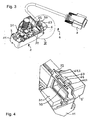
- the yarn cleaner measuring head 1 includes a measuring head housing 11 for receiving a yarn sensor, an electronic circuit, a Garnschneidmaschines and / or other components.
- a measuring head housing 11 for receiving a yarn sensor, an electronic circuit, a Garnschneidmaschines and / or other components.
- the Yarn sensor and the electronic circuit in a lower housing part 12, the Garnschneidmaschine accommodated in an upper housing part 13. Between the lower housing part 12 and the upper housing part 13, an anvil belonging to the Garnschneidmaschine 14 can be seen from the outside.
- the measuring head housing 11 may be made of metal or plastic.
- connection cable 4 is releasably connected to the Garnr insectsmesskopf 1. It serves both the power supply of the yarn cleaner measuring head 1 and the data transmission to and from the yarn cleaner measuring head 1. Preferably, it is a multi-core shielded connection cable.
- FIG. 1 based the connection cable 4 on a commercially available 15-wire game port cable, in which at a Meßkopf furnishen end 41 a (in FIG. 1 not visible) coupling was mounted in a coupling housing 5.
- end 42 carries the connection cable 4 a plug 7, z.
- FIG. 2 shows the Garnrurbanmesskopf 1 and the connection cable 4 of FIG. 1 but with the measuring head housing 11 partially exposed and the coupling housing 5 is detached from the measuring head housing 11.
- a printed circuit board 2 accommodated in the interior of the measuring head housing 11, more precisely in the lower housing part 12, can be seen, which carries at least parts of an electronic circuit.
- a measuring slot 22 which serves for receiving a (not shown) to be cleaned yarn and to which a (not shown) yarn sensor for scanning the yarn is attached.
- the yarn cleaner measuring head 1 has a measuring-head-side connection 3, and the connection cable 4 carries a cable-side connection 6 for producing a detachable connection between the yarn-cleaning measuring head 1 and the connection cable 4.
- the connection is both electrical and mechanical.
- the detachable electrical connection between the circuit board 2 and the connecting cable 4 is in the example of FIG. 2 designed as a plug connection.
- a plug 31 (see Fig. 3 ) appropriate.
- the z. B. is soldered on the circuit board 2.
- the connecting cable 4 carries the matching connector 31 to the connector 61, z. Hirose DF11-16DS-2C, as available from Hirose Electric Co., Ltd., Tokyo, Japan.
- the plug 31 and the coupling 61 together form a connector.
- the releasable mechanical connection between the measuring head housing 11 and the coupling housing 5 is designed as a snap connection.
- a connection means is at the top of the coupling housing 5 has a resilient tongue 63 with a projection or a nose 64 (see Fig. 4 ) appropriate.
- a bracket 32 having an elongated opening 33.
- pivot cams 62.1, 62.2 are mounted, which lie on a common line and together form a pivot axis .
- On the underside of the measuring head housing 11 are as a counterpart and pivot bearing for the pivot cams 62.1, 62.2 corresponding cam holder 34.1, 34.2 (see Fig. 5 ) available.
- the pivot cams 62.1, 62.2 can be inserted into the cam holders 34.1, 34.2 and, if necessary, removed therefrom.
- the pivoting cams 62.1, 62.2 and the cam holders 34.1, 34.2 act together as a hinge, about which the coupling housing 5 and the measuring head housing 11 are mutually pivotable.
- the pivoting cams 62.1, 62.2 are first inserted into the cam holders 34.1, 34.2. Then, the coupling housing 5 is pivoted toward the measuring head housing 11, wherein the pivot cams 62.1, 62.2 mounted in the cam holders 34.1, 34.2 define the pivot axis.
- the tongue 63 is inserted into the opening 33. In this case, an inclined front surface of the projection 64 slides along an upper opening edge, so that the tongue 63 is deflected ever further down and biased.
- the tongue 63 again jumps upwards and snaps into the bracket 32.
- a vertical rear surface of the projection 64 then abuts the bracket 32 and forms with the bracket 32 a positive connection, which prevents retraction of the connecting cable 4.
- This latching connection thus releasably locks the coupling housing 5 on the measuring head housing 11.
- FIG. 3 illustrates the detachable connection between the measuring head 1 and the connecting cable 4, and FIGS. 4 and Fig. 5 shows a detailed view thereof.
- the latching connection between the measuring head housing 11 and the coupling housing 5 also ensures a strain relief for the cable connection 3. Only when the tongue 63 is pressed by an operator so far down that the projection 64 can pass through the opening 33, the snap connection by pulling out be solved again. To completely solve the connection and the coupling 61 must be pulled out of the connector 31.
- On both sides next to the tongue 63 are two positioning pins 65.1, 65.2, which also in the elongated opening 33 (see Fig. 4 ) and serve the lateral positioning of the connection cable 4.
- the coupling 61 is in the FIGS.
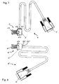
- FIG. 6 is the measuring head-side coupling housing 5 for the connecting cable 4 shown. Well visible are below the pivot cams 62.1, 62.2 and above the elastic tongue 63 with the projection 64.
- an output port 53 for the connection cable 4 is attached in a side wall 51 of the coupling housing 5.
- the connection cable 4 is pulled through the outlet opening.
- a (not shown) molded plastic spout is molded onto the cable jacket enclosing the measuring head end 41 of the connecting cable 4.
- the connecting cable 4 is then withdrawn until the grommet from the inside of the side wall 51 is present and thereby the connection cable 4 is prevented from exiting the clutch housing 5.
- Tensile forces acting on the connection cable 4 are absorbed by the spout, by the coupling housing and finally by the measuring head housing 11. This results in an effective strain relief for the connection cable. 4
- the coupling housing 5 is preferably made of a plastic by injection molding. With a replaceable slide in the injection mold, the option can be kept open to use the same injection mold to produce coupling housings with differently positioned and aligned outlet openings for the connection cable 4.
- the connection cable 4 according FIG. 7 has an outlet opening 53 in a side wall 51 of the coupling housing 5, while the connecting cable 4 'according to FIG. 8 an outlet opening 53 'in a rear wall 52' of the coupling housing 5 'has.
- the exit port could alternatively be in any other wall of the clutch housing, e.g. B. in the top or bottom wall, are. Embodiments with multiple exit openings in different walls are also possible.
- a prerequisite for the ease of manufacture of such a variety of variants of the coupling housing is that at least two walls 51, 52 of the coupling housing 5 (see Fig. 6 ) each have a sufficiently large area to accommodate the exit port 53.
- pivotally mounted pivot cams could be provided in the lower part of a snap or other connection.
Landscapes
- Engineering & Computer Science (AREA)
- Textile Engineering (AREA)
- Mechanical Engineering (AREA)
- Quality & Reliability (AREA)
- Details Of Connecting Devices For Male And Female Coupling (AREA)
- Filamentary Materials, Packages, And Safety Devices Therefor (AREA)
- Investigating Materials By The Use Of Optical Means Adapted For Particular Applications (AREA)
- Investigating Or Analyzing Materials By The Use Of Electric Means (AREA)
Claims (8)
- Tête de mesure pour nettoyeur de fil (1) avec
un boîtier de tête de mesure (11),
un circuit électronique (21) logé dans le boîtier de tête de mesure (11) et un branchement du côté de la tête de mesure (3) pour un câble de branchement électrique (4) pouvant être relié au circuit électronique (21),
caractérisée en ce que
le branchement du côté de la tête de mesure (3) est conçu pour établir une liaison pouvant être défaite entre la tête de mesure pour nettoyeur de fil (1) et le câble de branchement (4),
le branchement du côté de la tête de mesure (3) comportant des premiers moyens de liaison (32, 33) conçus pour établir une liaison enclenchée mécanique pouvant être défaite avec des deuxièmes moyens de liaison (63, 64, 65.1, 65.2) contenus par le câble de branchement (4), et
les premiers moyens de liaison comprennent une ouverture allongée (33) permettant la réception enclenchée d'une languette élastique (63) avec une saillie (64). - Tête de mesure pour nettoyeur de fil (1) selon la revendication 1, dans laquelle le branchement du côté de la tête de mesure (3) présente des troisièmes moyens de liaison (34.1, 34.2) distants des premiers moyens de liaison (32, 33) pour établir une liaison mécanique pouvant être défaite avec des quatrièmes moyens de liaison (62.1, 62.2) contenus par le câble de branchement (4).
- Tête de mesure pour nettoyeur de fil (1) selon la revendication 2, dans laquelle les troisièmes moyens de liaison (34.1, 34.2) sont conçus pour établir une liaison à type de charnière pouvant être défaite.
- Tête de mesure pour nettoyeur de fil (1) selon la revendication 3, dans laquelle les troisièmes moyens de liaison (34.1, 34.2) sont conçus comme un support pivotant pour des cames pivotantes (62.1, 62.2).
- Combinaison d'une tête de mesure pour nettoyeur de fil (1) selon l'une des revendications précédentes et d'un câble de branchement électrique (4), dans laquelle une extrémité (41) du câble de branchement (4) comprend un branchement du côté du câble (6) pour la liaison avec le circuit électronique (21) de la tête de mesure pour nettoyeur de fil (1),
le branchement du côté du câble (6) est conçu pour établir une liaison entre la tête de mesure pour nettoyeur de fil (1) et le câble de branchement (4),
le branchement du côté du câble (6) comprend un boîtier de branchement (5) avec des deuxièmes moyens de liaison (63, 64, 65.1, 65.2) qui sont conçus pour établir une liaison enclenchée mécanique pouvant être défaite avec des premiers moyens de liaison (32, 33) contenus dans le boîtier de tête de mesure (11),
l'extrémité (41) du câble de branchement (4) est reliée électriquement au circuit électronique (21),
la tête de mesure pour nettoyeur de fil (1) et le câble de branchement (4) sont reliés l'une à l'autre par une liaison pouvant être défait,
le boîtier de tête de mesure (11) est relié mécaniquement au câble de branchement (4) par une liaison enclenchée pouvant être défaite et
la liaison enclenchée pouvant être défaite comprend une languette élastique (63) d'une part et une ouverture allongée (33) recevant la languette élastique (63) d'autre part. - Combinaison selon la revendication 5, dans laquelle le boîtier de tête de mesure (11) est en outre relié mécaniquement au câble de branchement (4) par une liaison à type de charnière pouvant être défaite.
- Combinaison selon la revendication 6, dans laquelle la liaison à type de charnière est formée par un support pivotant (34.1, 34.2) et par des cames pivotantes (62.1, 62.2) supportées de façon pivotante dans le support pivotant (34.1, 34.2) et formant un axe de pivotement.
- Combinaison selon l'une des revendications 5 à 7, dans laquelle
le branchement du côté du câble (6) comprend un boîtier de branchement (5),
le câble (4) passe à travers une ouverture d'entrée et une ouverture de sortie (53) dans le boîtier de branchement (5),
le boîtier de branchement (5) présente au moins deux parois de boîtier (51, 52) sensiblement planes,
l'ouverture de sortie (53) est ménagée dans une première (51) des au moins deux parois de boîtier (51, 52) et
au moins une deuxième (52) des au moins deux parois de boîtier (51, 52) a des dimensions suffisamment grandes pour accueillir l'ouverture de sortie (53).
Applications Claiming Priority (2)
| Application Number | Priority Date | Filing Date | Title |
|---|---|---|---|
| CH8232008 | 2008-05-29 | ||
| PCT/CH2009/000167 WO2009143642A1 (fr) | 2008-05-29 | 2009-05-20 | Tête de mesure de nettoyeur de fil avec borne de câblage amovible |
Publications (3)
| Publication Number | Publication Date |
|---|---|
| EP2279146A1 EP2279146A1 (fr) | 2011-02-02 |
| EP2279146B1 EP2279146B1 (fr) | 2013-07-17 |
| EP2279146B2 true EP2279146B2 (fr) | 2016-08-31 |
Family
ID=39789729
Family Applications (1)
| Application Number | Title | Priority Date | Filing Date |
|---|---|---|---|
| EP09753401.0A Not-in-force EP2279146B2 (fr) | 2008-05-29 | 2009-05-20 | Tête de mesure de nettoyeur de fil avec borne de câblage amovible |
Country Status (4)
| Country | Link |
|---|---|
| EP (1) | EP2279146B2 (fr) |
| JP (1) | JP2011521271A (fr) |
| CN (1) | CN202107383U (fr) |
| WO (1) | WO2009143642A1 (fr) |
Families Citing this family (3)
| Publication number | Priority date | Publication date | Assignee | Title |
|---|---|---|---|---|
| CH703465A1 (de) | 2010-07-21 | 2012-01-31 | Uster Technologies Ag | Elektrische Schaltung mit verpolungsgeschütztem Verbindungsteil. |
| CZ2013450A3 (cs) * | 2013-06-12 | 2014-02-12 | Rieter Cz S.R.O. | Způsob a zařízení ke sledování lineárního útvaru |
| CN107059228A (zh) * | 2017-06-15 | 2017-08-18 | 苏州瑞众新材料科技有限公司 | 一种新型清纱装置 |
Family Cites Families (15)
| Publication number | Priority date | Publication date | Assignee | Title |
|---|---|---|---|---|
| GB1086064A (en) * | 1964-05-22 | 1967-10-04 | Newmark Ltd Louis | Improvements in apparatus for the detection and removal of faults in textile yarns and threads |
| DE3681481D1 (de) * | 1985-04-04 | 1991-10-24 | Commw Scient Ind Res Org | Ueberwachung von verunreinigungen in textilerzeugnissen. |
| EP0253934A1 (fr) * | 1986-07-25 | 1988-01-27 | Toray Industries, Inc. | Epurateur de fil |
| DE3927274A1 (de) * | 1989-08-18 | 1991-02-28 | Messerschmitt Boelkow Blohm | Verriegelung fuer eine mehrpolige steckverbindung |
| CH683293A5 (de) | 1991-12-20 | 1994-02-15 | Peyer Ag Siegfried | Fremdfasererkennung in Garnen. |
| US5234358A (en) * | 1992-06-09 | 1993-08-10 | Molex Incorporated | Strain relief shell for an electrical connector |
| US5749212A (en) * | 1995-06-06 | 1998-05-12 | Dixy Yarns, Inc. | Elastomeric core/staple fiber wrap yarn |
| EP0761853A1 (fr) | 1995-09-06 | 1997-03-12 | Zellweger Luwa Ag | Appareil pour le contrÔle d'un fil en mouvement |
| WO1997036032A1 (fr) * | 1996-03-27 | 1997-10-02 | Zellweger Luwa Ag | Procede et dispositif pour surveiller la qualite de fils |
| DE59814414D1 (de) | 1997-12-18 | 2010-01-07 | Uster Technologies Ag | Verfahren und Vorrichtung zur Ermittlung von Anteilen fester Stoffe in einem Prüfgut |
| JP4756411B2 (ja) * | 1998-03-25 | 2011-08-24 | ウステル・テヒノロジーズ・アクチエンゲゼルシヤフト | 長手方向に運動するテスト品の特性を測定する装置 |
| DE10118660A1 (de) | 2001-04-14 | 2002-10-17 | Schlafhorst & Co W | Garnreinigungseinrichtung an der Spulstelle einer Textilmaschine |
| DE10150581A1 (de) | 2001-10-12 | 2003-04-17 | Schlafhorst & Co W | Garnsensor |
| DE20204242U1 (de) * | 2002-03-16 | 2002-06-06 | Provertha Steckverbinder GmbH, 75180 Pforzheim | Bus-Gehäuse mit einem Steckverbinder mit Verriegelungseinrichtung |
| FR2904153B1 (fr) | 2006-07-21 | 2008-11-28 | Valeo Vision Sa | Dispositif de raccordement entre deux connecteurs d'alimentation electrique pour une lampe a decharge, d'un projecteur de vehicule automobile notamment |
-
2009
- 2009-05-20 EP EP09753401.0A patent/EP2279146B2/fr not_active Not-in-force
- 2009-05-20 CN CN2009901002717U patent/CN202107383U/zh not_active Expired - Fee Related
- 2009-05-20 JP JP2011512801A patent/JP2011521271A/ja active Pending
- 2009-05-20 WO PCT/CH2009/000167 patent/WO2009143642A1/fr not_active Ceased
Also Published As
| Publication number | Publication date |
|---|---|
| CN202107383U (zh) | 2012-01-11 |
| JP2011521271A (ja) | 2011-07-21 |
| EP2279146B1 (fr) | 2013-07-17 |
| EP2279146A1 (fr) | 2011-02-02 |
| WO2009143642A1 (fr) | 2009-12-03 |
Similar Documents
| Publication | Publication Date | Title |
|---|---|---|
| DE69105922T2 (de) | Optische Verbindung zu Rückwandplatinen. | |
| DE102008056036B4 (de) | Panel zur Aufnahme einer Anschluss- Box für Glasfaserkabel | |
| EP1912285B1 (fr) | Appareil électrique ou électronique | |
| EP2279146B2 (fr) | Tête de mesure de nettoyeur de fil avec borne de câblage amovible | |
| DE102013221651B4 (de) | Tragbares Ladekabel zum Laden eines Energiespeichers eines elektrisch betriebenen Fahrzeugs | |
| DE3851745T2 (de) | Gerät zum Einstellen einer Schaltungsplatte. | |
| DE102016101255A1 (de) | Verbinder | |
| DE3116869C2 (de) | Aufnahmevorrichtung für elektrische Steckbaugruppen enthaltende Geräteeinheiten der elektrischen Nachrichtentechnik | |
| EP2397601B1 (fr) | Traverse pour un appareil ménager, groupe pour l'assemblage d'un appareil ménager et appareil ménager | |
| DE102020210542A1 (de) | Verbundkabel-Verteilervorrichtung | |
| DE19643928A1 (de) | Anordnung zur Aufnahme eines Lichtwellenleitersteckverbinders, insbesondere für einen Bodentank | |
| DE102006030023B4 (de) | Wäschemaschine | |
| EP1188850A2 (fr) | Métiers à filer à bout libre | |
| DE3527914C2 (fr) | ||
| DE102020213884A1 (de) | Ladesteckerhalter für DC-Schnellladekabel | |
| DE10147809C2 (de) | Verbindungseinrichtung zum Herstellen einer zur Signalübertragung geeigneten Kopplung | |
| DE2919836C2 (fr) | ||
| DE19602156C1 (de) | Anschlußstecker zum Anschließen von Adern eines Kabels an ein elektrisches Gerät | |
| DE3336215A1 (de) | Fadenwaechter fuer ein spinnereimaschinen-streckwerk | |
| DE102018122500A1 (de) | Geräteeinbaudose für Kabelkanäle mit Saloontür Öffnung | |
| EP4223457B1 (fr) | Boitier pour une machine-outil portative électrique | |
| DE3236575A1 (de) | Steuer- und regelungsgeraet fuer heizungsanlagen | |
| EP3992684B1 (fr) | Dispositif adaptateur permettant d'établir de manière mobile une connexion de guidage lumineux, système, ainsi que procédé | |
| DE102009001755B4 (de) | Geschirrspülmaschine, insbesondere Haushaltsgeschirrspülmaschine | |
| DE3310688C2 (de) | Schaltkasten mit Scharnierbügeln am Stülpdeckel |
Legal Events
| Date | Code | Title | Description |
|---|---|---|---|
| PUAI | Public reference made under article 153(3) epc to a published international application that has entered the european phase |
Free format text: ORIGINAL CODE: 0009012 |
|
| 17P | Request for examination filed |
Effective date: 20101029 |
|
| AK | Designated contracting states |
Kind code of ref document: A1 Designated state(s): AT BE BG CH CY CZ DE DK EE ES FI FR GB GR HR HU IE IS IT LI LT LU LV MC MK MT NL NO PL PT RO SE SI SK TR |
|
| AX | Request for extension of the european patent |
Extension state: AL BA RS |
|
| DAX | Request for extension of the european patent (deleted) | ||
| 17Q | First examination report despatched |
Effective date: 20121011 |
|
| GRAP | Despatch of communication of intention to grant a patent |
Free format text: ORIGINAL CODE: EPIDOSNIGR1 |
|
| GRAS | Grant fee paid |
Free format text: ORIGINAL CODE: EPIDOSNIGR3 |
|
| GRAA | (expected) grant |
Free format text: ORIGINAL CODE: 0009210 |
|
| AK | Designated contracting states |
Kind code of ref document: B1 Designated state(s): AT BE BG CH CY CZ DE DK EE ES FI FR GB GR HR HU IE IS IT LI LT LU LV MC MK MT NL NO PL PT RO SE SI SK TR |
|
| REG | Reference to a national code |
Ref country code: GB Ref legal event code: FG4D Free format text: NOT ENGLISH |
|
| REG | Reference to a national code |
Ref country code: CH Ref legal event code: EP |
|
| REG | Reference to a national code |
Ref country code: IE Ref legal event code: FG4D Free format text: LANGUAGE OF EP DOCUMENT: GERMAN |
|
| REG | Reference to a national code |
Ref country code: AT Ref legal event code: REF Ref document number: 622070 Country of ref document: AT Kind code of ref document: T Effective date: 20130815 |
|
| REG | Reference to a national code |
Ref country code: DE Ref legal event code: R096 Ref document number: 502009007608 Country of ref document: DE Effective date: 20130912 |
|
| REG | Reference to a national code |
Ref country code: NL Ref legal event code: VDEP Effective date: 20130717 |
|
| REG | Reference to a national code |
Ref country code: LT Ref legal event code: MG4D |
|
| PG25 | Lapsed in a contracting state [announced via postgrant information from national office to epo] |
Ref country code: LT Free format text: LAPSE BECAUSE OF FAILURE TO SUBMIT A TRANSLATION OF THE DESCRIPTION OR TO PAY THE FEE WITHIN THE PRESCRIBED TIME-LIMIT Effective date: 20130717 Ref country code: HR Free format text: LAPSE BECAUSE OF FAILURE TO SUBMIT A TRANSLATION OF THE DESCRIPTION OR TO PAY THE FEE WITHIN THE PRESCRIBED TIME-LIMIT Effective date: 20130717 Ref country code: CY Free format text: LAPSE BECAUSE OF FAILURE TO SUBMIT A TRANSLATION OF THE DESCRIPTION OR TO PAY THE FEE WITHIN THE PRESCRIBED TIME-LIMIT Effective date: 20130918 Ref country code: IS Free format text: LAPSE BECAUSE OF FAILURE TO SUBMIT A TRANSLATION OF THE DESCRIPTION OR TO PAY THE FEE WITHIN THE PRESCRIBED TIME-LIMIT Effective date: 20131117 Ref country code: SE Free format text: LAPSE BECAUSE OF FAILURE TO SUBMIT A TRANSLATION OF THE DESCRIPTION OR TO PAY THE FEE WITHIN THE PRESCRIBED TIME-LIMIT Effective date: 20130717 Ref country code: PT Free format text: LAPSE BECAUSE OF FAILURE TO SUBMIT A TRANSLATION OF THE DESCRIPTION OR TO PAY THE FEE WITHIN THE PRESCRIBED TIME-LIMIT Effective date: 20131118 Ref country code: NO Free format text: LAPSE BECAUSE OF FAILURE TO SUBMIT A TRANSLATION OF THE DESCRIPTION OR TO PAY THE FEE WITHIN THE PRESCRIBED TIME-LIMIT Effective date: 20131017 |
|
| PG25 | Lapsed in a contracting state [announced via postgrant information from national office to epo] |
Ref country code: SI Free format text: LAPSE BECAUSE OF FAILURE TO SUBMIT A TRANSLATION OF THE DESCRIPTION OR TO PAY THE FEE WITHIN THE PRESCRIBED TIME-LIMIT Effective date: 20130717 Ref country code: ES Free format text: LAPSE BECAUSE OF FAILURE TO SUBMIT A TRANSLATION OF THE DESCRIPTION OR TO PAY THE FEE WITHIN THE PRESCRIBED TIME-LIMIT Effective date: 20131028 Ref country code: FI Free format text: LAPSE BECAUSE OF FAILURE TO SUBMIT A TRANSLATION OF THE DESCRIPTION OR TO PAY THE FEE WITHIN THE PRESCRIBED TIME-LIMIT Effective date: 20130717 Ref country code: PL Free format text: LAPSE BECAUSE OF FAILURE TO SUBMIT A TRANSLATION OF THE DESCRIPTION OR TO PAY THE FEE WITHIN THE PRESCRIBED TIME-LIMIT Effective date: 20130717 Ref country code: LV Free format text: LAPSE BECAUSE OF FAILURE TO SUBMIT A TRANSLATION OF THE DESCRIPTION OR TO PAY THE FEE WITHIN THE PRESCRIBED TIME-LIMIT Effective date: 20130717 Ref country code: NL Free format text: LAPSE BECAUSE OF FAILURE TO SUBMIT A TRANSLATION OF THE DESCRIPTION OR TO PAY THE FEE WITHIN THE PRESCRIBED TIME-LIMIT Effective date: 20130717 Ref country code: GR Free format text: LAPSE BECAUSE OF FAILURE TO SUBMIT A TRANSLATION OF THE DESCRIPTION OR TO PAY THE FEE WITHIN THE PRESCRIBED TIME-LIMIT Effective date: 20131018 |
|
| PG25 | Lapsed in a contracting state [announced via postgrant information from national office to epo] |
Ref country code: CY Free format text: LAPSE BECAUSE OF FAILURE TO SUBMIT A TRANSLATION OF THE DESCRIPTION OR TO PAY THE FEE WITHIN THE PRESCRIBED TIME-LIMIT Effective date: 20130717 |
|
| PLBI | Opposition filed |
Free format text: ORIGINAL CODE: 0009260 |
|
| PG25 | Lapsed in a contracting state [announced via postgrant information from national office to epo] |
Ref country code: SK Free format text: LAPSE BECAUSE OF FAILURE TO SUBMIT A TRANSLATION OF THE DESCRIPTION OR TO PAY THE FEE WITHIN THE PRESCRIBED TIME-LIMIT Effective date: 20130717 Ref country code: RO Free format text: LAPSE BECAUSE OF FAILURE TO SUBMIT A TRANSLATION OF THE DESCRIPTION OR TO PAY THE FEE WITHIN THE PRESCRIBED TIME-LIMIT Effective date: 20130717 Ref country code: DK Free format text: LAPSE BECAUSE OF FAILURE TO SUBMIT A TRANSLATION OF THE DESCRIPTION OR TO PAY THE FEE WITHIN THE PRESCRIBED TIME-LIMIT Effective date: 20130717 Ref country code: CZ Free format text: LAPSE BECAUSE OF FAILURE TO SUBMIT A TRANSLATION OF THE DESCRIPTION OR TO PAY THE FEE WITHIN THE PRESCRIBED TIME-LIMIT Effective date: 20130717 Ref country code: EE Free format text: LAPSE BECAUSE OF FAILURE TO SUBMIT A TRANSLATION OF THE DESCRIPTION OR TO PAY THE FEE WITHIN THE PRESCRIBED TIME-LIMIT Effective date: 20130717 |
|
| 26 | Opposition filed |
Opponent name: SAURER GERMANY GMBH & CO. KG Effective date: 20140415 |
|
| PLAX | Notice of opposition and request to file observation + time limit sent |
Free format text: ORIGINAL CODE: EPIDOSNOBS2 |
|
| REG | Reference to a national code |
Ref country code: DE Ref legal event code: R026 Ref document number: 502009007608 Country of ref document: DE Effective date: 20140415 |
|
| PGFP | Annual fee paid to national office [announced via postgrant information from national office to epo] |
Ref country code: CH Payment date: 20140513 Year of fee payment: 6 Ref country code: TR Payment date: 20140421 Year of fee payment: 6 Ref country code: IT Payment date: 20140512 Year of fee payment: 6 |
|
| PLBB | Reply of patent proprietor to notice(s) of opposition received |
Free format text: ORIGINAL CODE: EPIDOSNOBS3 |
|
| PG25 | Lapsed in a contracting state [announced via postgrant information from national office to epo] |
Ref country code: LU Free format text: LAPSE BECAUSE OF FAILURE TO SUBMIT A TRANSLATION OF THE DESCRIPTION OR TO PAY THE FEE WITHIN THE PRESCRIBED TIME-LIMIT Effective date: 20140520 |
|
| GBPC | Gb: european patent ceased through non-payment of renewal fee |
Effective date: 20140520 |
|
| PG25 | Lapsed in a contracting state [announced via postgrant information from national office to epo] |
Ref country code: MC Free format text: LAPSE BECAUSE OF FAILURE TO SUBMIT A TRANSLATION OF THE DESCRIPTION OR TO PAY THE FEE WITHIN THE PRESCRIBED TIME-LIMIT Effective date: 20130717 |
|
| REG | Reference to a national code |
Ref country code: IE Ref legal event code: MM4A |
|
| REG | Reference to a national code |
Ref country code: FR Ref legal event code: ST Effective date: 20150130 |
|
| PG25 | Lapsed in a contracting state [announced via postgrant information from national office to epo] |
Ref country code: IE Free format text: LAPSE BECAUSE OF NON-PAYMENT OF DUE FEES Effective date: 20140520 |
|
| PG25 | Lapsed in a contracting state [announced via postgrant information from national office to epo] |
Ref country code: FR Free format text: LAPSE BECAUSE OF NON-PAYMENT OF DUE FEES Effective date: 20140602 Ref country code: GB Free format text: LAPSE BECAUSE OF NON-PAYMENT OF DUE FEES Effective date: 20140520 |
|
| REG | Reference to a national code |
Ref country code: AT Ref legal event code: MM01 Ref document number: 622070 Country of ref document: AT Kind code of ref document: T Effective date: 20140520 |
|
| PG25 | Lapsed in a contracting state [announced via postgrant information from national office to epo] |
Ref country code: AT Free format text: LAPSE BECAUSE OF NON-PAYMENT OF DUE FEES Effective date: 20140520 |
|
| REG | Reference to a national code |
Ref country code: CH Ref legal event code: PL |
|
| PG25 | Lapsed in a contracting state [announced via postgrant information from national office to epo] |
Ref country code: IT Free format text: LAPSE BECAUSE OF NON-PAYMENT OF DUE FEES Effective date: 20150520 Ref country code: LI Free format text: LAPSE BECAUSE OF NON-PAYMENT OF DUE FEES Effective date: 20150531 Ref country code: CH Free format text: LAPSE BECAUSE OF NON-PAYMENT OF DUE FEES Effective date: 20150531 |
|
| PG25 | Lapsed in a contracting state [announced via postgrant information from national office to epo] |
Ref country code: MT Free format text: LAPSE BECAUSE OF FAILURE TO SUBMIT A TRANSLATION OF THE DESCRIPTION OR TO PAY THE FEE WITHIN THE PRESCRIBED TIME-LIMIT Effective date: 20130717 |
|
| PG25 | Lapsed in a contracting state [announced via postgrant information from national office to epo] |
Ref country code: BG Free format text: LAPSE BECAUSE OF FAILURE TO SUBMIT A TRANSLATION OF THE DESCRIPTION OR TO PAY THE FEE WITHIN THE PRESCRIBED TIME-LIMIT Effective date: 20130717 |
|
| PG25 | Lapsed in a contracting state [announced via postgrant information from national office to epo] |
Ref country code: HU Free format text: LAPSE BECAUSE OF FAILURE TO SUBMIT A TRANSLATION OF THE DESCRIPTION OR TO PAY THE FEE WITHIN THE PRESCRIBED TIME-LIMIT; INVALID AB INITIO Effective date: 20090520 Ref country code: BE Free format text: LAPSE BECAUSE OF FAILURE TO SUBMIT A TRANSLATION OF THE DESCRIPTION OR TO PAY THE FEE WITHIN THE PRESCRIBED TIME-LIMIT Effective date: 20140531 |
|
| PUAH | Patent maintained in amended form |
Free format text: ORIGINAL CODE: 0009272 |
|
| STAA | Information on the status of an ep patent application or granted ep patent |
Free format text: STATUS: PATENT MAINTAINED AS AMENDED |
|
| PLAB | Opposition data, opponent's data or that of the opponent's representative modified |
Free format text: ORIGINAL CODE: 0009299OPPO |
|
| 27A | Patent maintained in amended form |
Effective date: 20160831 |
|
| AK | Designated contracting states |
Kind code of ref document: B2 Designated state(s): AT BE BG CH CY CZ DE DK EE ES FI FR GB GR HR HU IE IS IT LI LT LU LV MC MK MT NL NO PL PT RO SE SI SK TR |
|
| REG | Reference to a national code |
Ref country code: DE Ref legal event code: R102 Ref document number: 502009007608 Country of ref document: DE |
|
| R26 | Opposition filed (corrected) |
Opponent name: SAURER GERMANY GMBH & CO. KG Effective date: 20140415 |
|
| PGFP | Annual fee paid to national office [announced via postgrant information from national office to epo] |
Ref country code: DE Payment date: 20170523 Year of fee payment: 9 |
|
| PG25 | Lapsed in a contracting state [announced via postgrant information from national office to epo] |
Ref country code: TR Free format text: LAPSE BECAUSE OF NON-PAYMENT OF DUE FEES Effective date: 20150520 |
|
| PG25 | Lapsed in a contracting state [announced via postgrant information from national office to epo] |
Ref country code: MK Free format text: LAPSE BECAUSE OF FAILURE TO SUBMIT A TRANSLATION OF THE DESCRIPTION OR TO PAY THE FEE WITHIN THE PRESCRIBED TIME-LIMIT Effective date: 20130717 |
|
| REG | Reference to a national code |
Ref country code: DE Ref legal event code: R119 Ref document number: 502009007608 Country of ref document: DE |
|
| PG25 | Lapsed in a contracting state [announced via postgrant information from national office to epo] |
Ref country code: DE Free format text: LAPSE BECAUSE OF NON-PAYMENT OF DUE FEES Effective date: 20181201 |
|
| P01 | Opt-out of the competence of the unified patent court (upc) registered |
Effective date: 20230515 |