EP2279981A1 - Verriegelungsvorrichtung für einen Batterieblock für ein Flurföderzeug - Google Patents
Verriegelungsvorrichtung für einen Batterieblock für ein Flurföderzeug Download PDFInfo
- Publication number
- EP2279981A1 EP2279981A1 EP10007449A EP10007449A EP2279981A1 EP 2279981 A1 EP2279981 A1 EP 2279981A1 EP 10007449 A EP10007449 A EP 10007449A EP 10007449 A EP10007449 A EP 10007449A EP 2279981 A1 EP2279981 A1 EP 2279981A1
- Authority
- EP
- European Patent Office
- Prior art keywords
- lever
- battery
- locking device
- removal
- battery block
- Prior art date
- Legal status (The legal status is an assumption and is not a legal conclusion. Google has not performed a legal analysis and makes no representation as to the accuracy of the status listed.)
- Granted
Links
Images



Classifications
-
- B—PERFORMING OPERATIONS; TRANSPORTING
- B60—VEHICLES IN GENERAL
- B60K—ARRANGEMENT OR MOUNTING OF PROPULSION UNITS OR OF TRANSMISSIONS IN VEHICLES; ARRANGEMENT OR MOUNTING OF PLURAL DIVERSE PRIME-MOVERS IN VEHICLES; AUXILIARY DRIVES FOR VEHICLES; INSTRUMENTATION OR DASHBOARDS FOR VEHICLES; ARRANGEMENTS IN CONNECTION WITH COOLING, AIR INTAKE, GAS EXHAUST OR FUEL SUPPLY OF PROPULSION UNITS IN VEHICLES
- B60K1/00—Arrangement or mounting of electrical propulsion units
- B60K1/04—Arrangement or mounting of electrical propulsion units of the electric storage means for propulsion
-
- B—PERFORMING OPERATIONS; TRANSPORTING
- B66—HOISTING; LIFTING; HAULING
- B66F—HOISTING, LIFTING, HAULING OR PUSHING, NOT OTHERWISE PROVIDED FOR, e.g. DEVICES WHICH APPLY A LIFTING OR PUSHING FORCE DIRECTLY TO THE SURFACE OF A LOAD
- B66F9/00—Devices for lifting or lowering bulky or heavy goods for loading or unloading purposes
- B66F9/06—Devices for lifting or lowering bulky or heavy goods for loading or unloading purposes movable, with their loads, on wheels or the like, e.g. fork-lift trucks
- B66F9/075—Constructional features or details
- B66F9/07513—Details concerning the chassis
- B66F9/07531—Battery compartments
- B66F9/07536—Battery stoppers, i.e. means to hold battery in position
-
- B—PERFORMING OPERATIONS; TRANSPORTING
- B60—VEHICLES IN GENERAL
- B60Y—INDEXING SCHEME RELATING TO ASPECTS CROSS-CUTTING VEHICLE TECHNOLOGY
- B60Y2200/00—Type of vehicle
- B60Y2200/10—Road Vehicles
- B60Y2200/15—Fork lift trucks, Industrial trucks
Definitions
- the invention relates to a locking device for a battery pack for a truck according to claim 1.
- Such a locking device is approximately out DE 10 2006 057 490 Al known.
- Two levers of the locking device form a toggle lever closure, wherein a first lever is mounted about a vehicle-fixed axis.
- the second lever is pivotally mounted on the first lever and detects a wall surface of the battery pack by means of a buffer. In the unlocked position, the battery block can be moved out to one side horizontally.
- the battery In the known industrial trucks, the battery is usually stored on roller systems. This can lead to subsidence on the roller contact surfaces due to shocks during transport, whereby the force to be expended when removing the battery pack is quite high, because first a breakout force must be overcome. Furthermore, the battery is still at the stop after unlocking, therefore remains a hand for the removal little or no space to reach behind the battery.
- the invention has for its object to provide a locking device for a battery pack for a truck in which a quick and easy battery change is possible and the removal of the battery is facilitated.
- the locking device according to the invention for a battery block for a truck comprises a battery lock for releasably locking the battery pack in a frame of the truck and a separate, mounted on a vehicle-mounted axle removal lever to support a removal of the battery pack.
- the removal lever has a handle portion formed by a first lever arm and a lever portion formed by a second lever arm. The lever section pushes the battery block partially during removal from the frame.
- the battery lock After loosening the battery lock can be partially pushed out of the frame of the truck with the help of the removal lever of the battery block. This facilitates the removal of the battery pack, as a breakaway force can be easily applied by the leverage. Because a wall of the battery pack is often flush with the vehicle frame, the removal is also facilitated by the fact that the battery pack is pushed a little way out of the vehicle frame and is easier to grip.
- the separate arrangement of the removal lever allows its operation regardless of an operation of the battery lock, on the other hand is given by an independence in dimensioning and choice of material.
- the locking device according to the invention allows the use of unmodified standard batteries.
- the removal lever is connected via the axis with the battery lock. So the axle can be safely stored on the already securely mounted battery lock. Both actuators, ie battery lock and removal lever, are thus arranged close to each other, which simplifies the accessibility and operation.
- the battery lock preferably has at least one lever.
- the axis is an extension of an axis of the battery lock, whereby the construction is simplified.
- the handle portion of the removal lever on a first stop stop which limits the mobility of the not locked by the battery lock battery block out of the frame of the truck in a rest position of the removal lever.
- the handle portion of the removal lever on a second stop stop, which limits the insertion of the battery pack into the frame of the truck in a rest position of the removal lever. If a battery pack is inserted into the truck, this is only possible up to the second stop stop.
- the battery pack then protrudes from the vehicle frame by a specified length. This length depends on the position of the second retaining stop on the handle portion of the removal lever and leaves enough space, preferably 3 cm to 15 cm, that a hand behind a wall of the battery block can not be trapped.
- the first stop stop is arranged closer to the axis than the second stop stop.
- the mobility of the not by the battery lock Locked battery block smaller and the supernatant of an inserted to the second stop stop battery block from the vehicle frame larger. This can be easily implemented in one piece, in a single contour of the removal lever.
- an upper stop of the removal lever rests against a further stop when the removal lever is moved into a release position. In this way, the removal lever can only be pivoted to a defined position. The removal lever can not be pivoted so far that the lever portion is moved beyond an upper edge of the battery pack, so that he can no longer detect this.
- the further stop is attached to a carrier device of the battery lock, whereby it is arranged fixed to the vehicle and in particular can be integrally connected to the carrier device.
- the lever portion of the removal lever on a voltage applied to the removal of the battery block on the lever contour which transmits different leverage forces on the battery pack in different positions of the removal lever.
- the lever contour of the lever portion is curved such that upon actuation of the removal lever from a rest position to a release position, the leverage decreases with increasing expulsion of the battery pack.
- the leverage is initially particularly large to exercise the necessary breakout force.
- the acting lever arm of the lever portion becomes longer due to the curved contour; the battery pack can be pushed out further.
- the lever portion of the removal lever is dimensioned so that upon actuation of the removal lever in a release position of the battery pack is pushed so far out of the frame of the truck that the battery pack protrudes 3 cm to 15 cm from the frame.
- the battery pack can now be easily grasped and completely pulled out.
- the removal lever can preferably be biased by means of a return spring in a rest position, whereby the correct positioning of the removal lever and in particular the holding stops is ensured.
- the battery lock on two cooperating levers, wherein a first lever is mounted about a vehicle-fixed axis and a second lever is pivotally mounted on the first lever, such that the second lever detects at least one wall surface of the battery block by clamping.
- a battery lock as described in the introduction DE 10 2006 057 490 A1 is known.
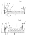
- FIG. 1 a locking device is shown which comprises a battery lock 10 and a removal lever 20.
- the battery lock 10 has a support device 12, to which a first bow-shaped lever 13 is articulated.
- a second lever 14 is articulated by means of a bearing pin on the first lever 13.
- the removal lever 20 is pivotably mounted about an axis 11 by means of a bolt connected to the support device 12.
- the removal lever 20 has a first lever arm, which forms a handle portion 21, as well as an approximately right-angled to the first lever arm angled second lever arm, which forms a lever portion 22.
- the handle portion 21 In a rest position of the removal lever, the handle portion 21 extends parallel to the first lever 13 of the battery lock 10 when it is in a locking position.
- a rest stop 23, at a End of the lever portion 22 is formed near the axis 11, is in the rest position of the take-off lever 20 against a counter-stop 19, which is formed by an angled portion of the support device.
- the movement of the removal lever 20 is thus limited, so that according to Fig. 2 the handle portion 21 is not movable from the horizontal rest position in the direction of battery block.
- a return spring 18 biases the removal lever 20 in this rest position.
- Fig. 2 shows a battery pack 30 which is arranged in a frame 1 shown only indicated an industrial truck.
- the battery pack 30 includes a battery 31 housed in a battery tray 32.
- the locking device according to the invention is mounted on a holding plate 2 fixedly connected to the frame 1.
- the battery pack 30 is fully inserted into the frame 1 of the truck and is held firmly in place by the battery lock 10.
- the second lever 14 of the battery lock 10 is provided at an angled portion with a buffer 16 made of plastic and engages behind a wall surface 33 of the battery tray 32, which is clamped between the second lever 14 and the support device 12.
- First and second levers 13, 14 act like a toggle closure.
- the buffer 16 acts against the wall surface 33 and generates a bias on exceeding the dead center of the two levers 13, 14 of the battery lock 10 when the first lever 13 from a raised in the in the Figures 1 and 2 shown horizontal locking position is pivoted.
- wall sections of the battery block 12 project upwards beyond the recorded battery.
- the buffer 16 therefore engage the inside of the end wall 13 at the top, according to Figures 1 and 2 to hold the battery block 12 in this position against the support device 12 and to regulate.
- first lever 13 of the battery lock 10 is pivoted to remove the battery pack 30 in the release position, and the second lever 14 pivots, and the buffer 16 is pivoted over the edge of the wall surface 33 of the battery block 30.
- the battery lock 10 is shown in the release position.
- the removal lever 20 is biased in its rest position by the return spring 18 with the rest stop 23 on the counter-stop 19 of the Suervorrich-. 12.
- the center of gravity of the removal lever can also be chosen so that the return spring 18 can be dispensed with.
- the battery lock 10 is unlocked ( Fig. 3 ).
- the removal lever 20 is operated against the force of the return spring 18, wherein the lever portion 21, as in Fig. 4 shown, with the wall surface 33 of the battery pack 30 comes into contact.
- the first retaining stop 24 is swung out of the region of the battery trough 32.
- the lever portion 21 has a curved lever contour 25, which initially acts on a first contact of the lever portion 21 with the wall surface 33 of the battery tray 32, a small lever length A for a high power gain, with a breakaway force can be applied with ease.
- the battery pack 30 can be inserted and ejected through an opening 3 of the frame 1.
- a supporting structure 4 of the frame above the opening 3 is intended to prevent unintentional gripping of the battery tray 32 during ejection.
- Fig. 5 Upon further pivoting of the removal lever 20 after Fig. 5 pushes the lever section 22 by the lever contour 25 with increasing lever length against the wall surface 33 of the battery pack 30 and pushes it out of its investment position.
- a release position ie at maximum deflection and maximum lever length A 'of the removal lever 20 of the battery block is pushed by a distance B from the frame 1 of the truck that one of the locking device opposite end of the battery pack 30 is pushed so far through the opening 3, that the battery tray 32 can be easily engaged behind for complete removal, for example, by the driver.
- the release position of the take-off lever 20 is defined by abutment of an upper stopper 28 formed at one end of the handle portion 21 near the axis 11 on the counter-stopper 19.
- the removal lever In order to fully insert the battery pack 30 into the frame 1, the removal lever must be raised against the force of the return spring 18 so that the wall surface 33 can be pushed under the second retention stopper 26. If the wall surface 33 has also passed the first holding stop 24 ( Fig. 7 ), the removal lever falls into the rest position, the first holding stop now prevents the battery block from rolling back. An operator now has both hands free in an inclined position of the truck in order to secure the battery block 30 by means of the battery lock 10 in the frame 1 of the truck.
Landscapes
- Engineering & Computer Science (AREA)
- Transportation (AREA)
- Mechanical Engineering (AREA)
- Chemical & Material Sciences (AREA)
- Combustion & Propulsion (AREA)
- Structural Engineering (AREA)
- Civil Engineering (AREA)
- Life Sciences & Earth Sciences (AREA)
- Geology (AREA)
- Battery Mounting, Suspending (AREA)
- Arrangement Or Mounting Of Propulsion Units For Vehicles (AREA)
Abstract
Description
- Die Erfindung bezieht sich auf eine Verriegelungsvorrichtung für einen Batterieblock für ein Flurförderzeug nach dem Patentanspruch 1.
- Eine derartige Verriegelungsvorrichtung ist etwa aus
DE 10 2006 057 490 Al bekannt geworden. Zwei Hebel der Verriegelungsvorrichtung bilden einen Kniehebelverschluss, wobei ein erster Hebel um eine fahrzeugfeste Achse gelagert ist. Der zweite Hebel ist am ersten Hebel schwenkbar gelagert und erfasst eine Wandfläche des Batterieblocks mit Hilfe eines Puffers. In der Entriegelungsposition kann der Batterieblock zu einer Seite horizontal herausbewegt werden. - Bei den bekannten Flurförderzeugen ist die Batterie in der Regel auf Rollensystemen gelagert. Hierbei kann es durch Stöße bei Transportfahrten zu Setzerscheinungen auf den Rollenkontaktflächen kommen, wodurch die aufzuwendende Kraft bei der Entnahme des Batterieblocks recht hoch ist, weil zuerst eine Losbrechkraft überwunden werden muss. Ferner steht die Batterie nach dem Entriegeln noch am Anschlag, daher bleibt einer Hand für die Entnahme nur wenig oder kein Platz die Batterie zu hintergreifen.
- Der Erfindung liegt die Aufgabe zugrunde, eine Verriegelungsvorrichtung für einen Batterieblock für ein Flurförderzeug zu schaffen, bei der ein schneller und einfacher Batteriewechsel möglich ist und die Entnahme der Batterie erleichtert ist.
- Die Aufgabe wird durch eine Verriegelungsvorrichtung mit den Merkmalen aus Anspruch 1 gelöst. Vorteilhafte Ausgestaltungen bilden den Gegenstand der Unteransprüche.
- Die erfindungsgemäße Verriegelungsvorrichtung für einen Batterieblock für ein Flurförderzeug umfasst eine Batterieverriegelung zur lösbaren Verriegelung des Batterieblocks in einem Rahmen des Flurförderzeugs und einen separaten, um eine fahrzeugfeste Achse gelagerten Entnahmehebel zur Unterstützung einer Entnahme des Batterieblocks. Der Entnahmehebel weist einen durch einen ersten Hebelarm gebildeten Griffabschnitt sowie einen durch einen zweiten Hebelarm gebildeten Hebelabschnitt auf. Der Hebelabschnitt schiebt bei der Entnahme den Batterieblock teilweise aus dem Rahmen heraus.
- Nach einem Lösen der Batterieverriegelung kann mit Hilfe des Entnahmehebels der Batterieblock teilweise aus dem Rahmen des Flurförderzeugs geschoben werden. Dies erleichtert die Entnahme des Batterieblocks, da durch die Hebelwirkung eine Losbrechkraft leicht aufgebracht werden kann. Weil eine Wandung des Batterieblocks häufig bündig mit dem Fahrzeugrahmen abschließt, ist die Entnahme auch dadurch erleichtert, dass der Batterieblock ein Stück weit aus dem Fahrzeugrahmen herausgeschoben wird und einfacher zu greifen ist. Die separate Anordnung des Entnahmehebels ermöglicht zum einen seine Betätigung unabhängig von einer Betätigung der Batterieverriegelung, zum anderen ist dadurch eine Unabhängigkeit bei Dimensionierung und Materialwahl gegeben. Die erfindungsgemäße Verriegelungsvorrichtung erlaubt die Verwendung unmodifizierter Standardbatterien.
- Bevorzugt ist der Entnahmehebel über die Achse mit der Batterieverriegelung verbunden. So kann die Achse an der ohnehin fest angebrachten Batterieverriegelung sicher gelagert werden. Beide Betätigungseinrichtungen, d.h. Batterieverriegelung und Entnahmehebel, sind dadurch nahe beieinander angeordnet, was die Zugänglichkeit und die Bedienung vereinfacht.
- Bevorzugt weist die Batterieverriegelung mindestens einen Hebel auf. Hierbei ist die Achse eine Verlängerung einer Achse der Batterieverriegelung, wodurch die Konstruktion vereinfacht wird.
- In einer bevorzugten Ausgestaltung weist der Griffabschnitt des Entnahmehebels einen ersten Halteanschlag auf, der in einer Ruheposition des Entnahmehebels die Beweglichkeit des nicht durch die Batterieverriegelung verriegelten Batterieblocks aus dem Rahmen des Flurförderzeugs heraus begrenzt. Dies hat den Vorteil, dass der Batterieblock auch nach einem Lösen der Batterieverriegelung nicht aus dem Fahrzeugrahmen herausrollen kann. Entsprechend kann der Batterieblock auch bei einem Einschieben nicht wieder herausrollen. Ist ein Wechsel der Batterie bei einer geneigten Lage des Flurförderzeugs erforderlich oder hat sich die Batterieverriegelung unbeabsichtigt gelöst, so bleibt der Batterieblock in seiner Beweglichkeit eingeschränkt, solange der Entnahmehebel nicht betätigt wird. Verletzungen oder Beschädigungen können so vermieden werden.
- In einer bevorzugten Ausgestaltung weist der Griffabschnitt des Entnahmehebels einen zweiten Halteanschlag auf, der in einer Ruheposition des Entnahmehebels den Einschub des Batterieblocks in den Rahmen des Flurförderzeugs hinein begrenzt. Wird ein Batterieblock in das Flurförderzeug eingeschoben, ist dies nur bis zu dem zweiten Halteanschlag möglich. Der Batterieblock steht dann noch um eine festgelegte Länge aus dem Fahrzeugrahmen hervor. Diese Länge hängt von der Position des zweiten Halteanschlags am Griffabschnitt des Entnahmehebels ab und lässt ausreichend Platz, bevorzugt 3 cm bis 15 cm, dass eine eine Wandung des Batterieblocks hintergreifende Hand nicht eingeklemmt werden kann.
- Bevorzugt ist der erste Halteanschlag näher an der Achse angeordnet als der zweite Halteanschlag. Hierbei ist die Beweglichkeit des nicht durch die Batterieverriegelung arretierten Batterieblocks kleiner und der Überstand eines bis zum zweiten Halteanschlag eingeschobenen Batterieblocks aus dem Fahrzeugrahmen größer. Dies lässt sich auf einfache Weise einteilig, in einer einzelnen Konturierung des Entnahmehebels umsetzen.
- In einer bevorzugten Ausgestaltung liegt ein oberer Anschlag des Entnahmehebels an einem weiteren Anschlag an, wenn der Entnahmehebel in eine Freigabeposition verstellt wird. Auf diese Weise kann der Entnahmehebel nur bis zu einer definierten Position verschwenkt werden. Der Entnahmehebel lässt sich nicht so weit verschwenken, dass der Hebelabschnitt über einen oberen Rand des Batterieblocks hinaus bewegt wird, so dass er diesen nicht mehr erfassen kann.
- Bevorzugt ist der weitere Anschlag an einer Trägervorrichtung der Batterieverriegelung angebracht, wodurch er fahrzeugfest angeordnet ist und insbesondere einteilig mit der Trägervorrichtung verbunden sein kann.
- In einer bevorzugten Ausgestaltung weist der Hebelabschnitt des Entnahmehebels eine bei der Entnahme an dem Batterieblock anliegende Hebelkontur auf, die in unterschiedlichen Positionen des Entnahmehebels unterschiedliche Hebelkräfte auf den Batterieblock überträgt. Bevorzugt ist die Hebelkontur des Hebelabschnitts derart gekrümmt, dass bei der Betätigung des Entnahmehebels von einer Ruheposition in eine Freigabeposition die Hebelkraft mit zunehmendem Ausschub des Batterieblocks abnimmt. So ist bei einer Entnahme des Batterieblocks die Hebelkraft zunächst besonders groß, um die nötige Losbrechkraft auszuüben. Bei weiterer Betätigung des Hebels nach Überwinden der Losbrechkraft wird der wirkende Hebelarm des Hebelabschnitts durch die gekrümmte Kontur länger; der Batterieblock kann weiter ausgeschoben werden.
- Bevorzugt ist der Hebelabschnitt des Entnahmehebels so dimensioniert ist, dass bei der Betätigung des Entnahmehebels in eine Freigabeposition der Batterieblock so weit aus dem Rahmen des Flurförderzeugs ausgeschoben wird, dass der Batterieblock 3 cm bis 15 cm aus dem Rahmen heraussteht. Der Batterieblock kann nun leicht erfasst und vollständig herausgezogen werden.
- Der Entnahmehebel kann bevorzugt mittels einer Rückholfeder in eine Ruheposition vorgespannt werden, wodurch die korrekte Positionierung des Entnahmehebels und insbesondere der Halteanschläge gewährleistet ist.
- Bei einer Ausgestaltung der Erfindung weist die Batterieverriegelung zwei zusammenwirkende Hebel auf, wobei ein erster Hebel um eine fahrzeugfeste Achse gelagert ist und ein zweiter Hebel an dem ersten Hebel schwenkbar gelagert ist, derart, dass der zweite Hebel mindestens eine Wandfläche des Batterieblocks klemmend erfasst. Hierbei kann es sich insbesondere um eine Batterieverriegelung handeln, wie sie aus der eingangs genannten
DE 10 2006 057 490 A1 bekannt ist. - Ein Ausführungsbeispiel der Erfindung wird nachfolgend anhand von Zeichnungen näher erläutert.
- Fig. 1
- zeigt perspektivisch eine Verriegelungsvorrichtung nach der Erfindung in einer Verriegelungsstellung.
- Fig. 2
- zeigt in einer Seitenansicht die Verriegelungsvorrichtung nach
Fig. 1 mit einem Batterieblock in einem angedeuteten Rahmen und einem Ent- nahmehebel in einer Ruheposition. - Fig. 3
- zeigt die Verriegelungsvorrichtung nach
Fig. 2 mit geöffneter Batterie- verriegelung. - Fig. 4
- zeigt die Verriegelungsvorrichtung nach
Fig. 3 mit dem Entnahmehebel in einer ersten Position. - Fig. 5
- zeigt die Verriegelungsvorrichtung nach
Fig. 4 mit dem Entnahmehebel in einer Freigabeposition. - Fig. 6
- zeigt die Verriegelungsvorrichtung nach
Fig. 3 mit einem teilweise ein- geschobenen Batterieblock. - Fig. 7
- zeigt die Verriegelungsvorrichtung nach
Fig. 6 mit einem nahezu voll- ständig eingeschobenen Batterieblock. - In
Figur 1 ist eine Verriegelungsvorrichtung dargestellt, die eine Batterieverriegelung 10 und einen Entnahmehebel 20 umfasst. Die Batterieverriegelung 10 weist eine Trägervorrichtung 12 auf, an die ein erster bügelartiger Hebel 13 angelenkt ist. Ein zweiter Hebel 14 ist mit Hilfe eines Lagerbolzens an dem ersten Hebel 13 angelenkt. - Der Entnahmehebel 20 ist mittels eines mit der Trägervorrichtung 12 verbundenen Bolzens um eine Achse 11 schwenkbar gelagert. Der Entnahmehebel 20 weist einen ersten Hebelarm auf, der einen Griffabschnitt 21 bildet, sowie einen etwa rechtwinklig zum ersten Hebelarm abgewinkelten zweiten Hebelarm, der einen Hebelabschnitt 22 bildet. In einer Ruheposition des Entnahmehebels verläuft der Griffabschnitt 21 parallel zu dem ersten Hebel 13 der Batterieverriegelung 10, wenn diese sich in einer Verriegelungsstellung befindet. Ein Ruheanschlag 23, der an einem Ende des Hebelabschnitts 22 nahe der Achse 11 gebildet ist, liegt in der Ruheposition des Entnahmehebels 20 an einem Gegenanschlag 19 an, welcher von einem abgewinkelten Teil der Trägervorrichtung gebildet ist. Die Bewegung des Entnahmehebels 20 ist somit begrenzt, so dass gemäß
Fig. 2 der Griffabschnitt 21 aus der waagerechten Ruheposition nicht weiter in Richtung Batterieblock beweglich ist. Eine Rückholfeder 18 spannt den Entnahmehebel 20 in diese Ruheposition vor. -
Fig. 2 zeigt einen Batterieblock 30, der in einem nur angedeutet dargestellten Rahmen 1 eines Flurförderzeugs angeordnet ist. Der Batterieblock 30 umfasst eine Batterie 31, die in einem Batterietrog 32 untergebracht ist. Die erfindungsgemäße Verriegelungsvorrichtung ist an einem fest mit dem Rahmen 1 verbundenen Halteblech 2 montiert. Der Batterieblock 30 ist vollständig in den Rahmen 1 des Flurförderzeugs eingeschoben und wird von der Batterieverriegelung 10 fest an seinem Platz gehalten. Der zweite Hebel 14 der Batterieverriegelung 10 ist an einem abgewinkelten Abschnitt mit einem Puffer 16 aus Kunststoff versehen und hintergreift eine Wandfläche 33 des Batterietrogs 32, wobei diese zwischen dem zweiten Hebel 14 und der Trägervorrichtung 12 eingeklemmt ist. Erster und zweiter Hebel 13, 14 wirken wie ein Kniehebelverschluss zusammen. In der Verriegelungsposition, wie sie in denFiguren 1 und 2 dargestellt ist, wirkt der Puffer 16 gegen die Wandfläche 33 und erzeugt eine Vorspannung bei Überschreiten des Totpunktes der beiden Hebel 13, 14 der Batterieverriegelung 10, wenn der erste Hebel 13 von einer angehobenen in die in denFiguren 1 und 2 dargestellte horizontale Verriegelungsposition verschwenkt wird. Bekanntlich stehen Wandabschnitte des Batterieblocks 12 nach oben über die aufgenommene Batterie über. Der Puffer 16 greifen daher auf die Innenseite der Stirnwand 13 oben an, um gemäßFiguren 1 und 2 den Batterieblock 12 in dieser Position gegen die Trägervorrichtung 12 zu halten und zu vernegeln. - Wird der erste Hebel 13 der Batterieverriegelung 10 zur Entnahme des Batterieblocks 30 in die Freigabeposition verschwenkt, verschwenkt sich auch der zweite Hebel 14, und der Puffer 16 wird über den Rand der Wandfläche 33 des Batterieblocks 30 geschwenkt. In den
Figuren 3 bis 7 ist die Batterieverriegelung 10 in der Freigabeposition dargestellt. - Der Entnahmehebel 20 liegt in seiner Ruheposition durch die Rückholfeder 18 vorgespannt mit dem Ruheanschlag 23 an dem Gegenanschlag 19 der Trägervorrich-. tung 12 an. Der Schwerpunkt des Entnahmehebels kann auch so gewählt sein, dass auf die Rückholfeder 18 verzichtet werden kann. Zur Entnahme des Batterieblocks 30 ist die Batterieverriegelung 10 entriegelt (
Fig. 3 ). Ein erster Halteanschlag 24, der an dem Griffabschnitt 21 des Entnahmehebels 20 angeordnet ist und in den Batterietrog 32 hineinreicht, verhindert ein Herausrollen des Batterieblocks 30, falls das Flurförderzeug in einer abschüssigen Lage abgestellt sein sollte. - Nun wird der Entnahmehebel 20 gegen die Kraft der Rückholfeder 18 betätigt, wobei der Hebelabschnitt 21, wie in
Fig. 4 gezeigt, mit der Wandfläche 33 des Batterieblocks 30 in Kontakt tritt. Gleichzeitig wird der erste Halteanschlag 24 aus dem Bereich des Batterietrogs 32 herausgeschwenkt. Der Hebelabschnitt 21 weist eine gekrümmte Hebelkontur 25 auf, wodurch bei einem ersten Kontakt des Hebelabschnitts 21 mit der Wandfläche 33 des Batterietrogs 32 zunächst eine kleine Hebellänge A für eine hohe Kraftverstärkung wirkt, mit der eine Losbrechkraft erleichtert aufgebracht werden kann. - Der Batterieblock 30 kann durch eine Öffnung 3 des Rahmens 1 ein- und ausgeschoben werden. Eine tragende Struktur 4 des Rahmens oberhalb der Öffnung 3 soll ein unbeabsichtigtes Greifen des Batterietrogs 32 beim Ausschub verhindern. Bei weiterer Verschwenkung des Entnahmehebels 20 nach
Fig. 5 drückt der Hebelabschnitt 22 durch die Hebelkontur 25 mit zunehmender Hebellänge gegen die Wandfläche 33 des Batterieblocks 30 und schiebt diesen aus seiner Anlageposition heraus. In einer Freigabeposition, d.h. bei maximaler Auslenkung und maximaler Hebellänge A' des Entnahmehebels 20 ist der Batterieblock um eine Strecke B aus dem Rahmen 1 des Flurförderzeugs ausgeschoben, dass ein der Verriegelungsvorrichtung gegenüberliegendes Ende des Batterieblocks 30 so weit durch die Öffnung 3 herausgeschoben ist, dass der Batterietrog 32 bequem zur vollständigen Entnahme beispielsweise durch den Fahrzeugführer hintergriffen werden kann. Die Freigabeposition des Entnahmehebels 20 ist durch das Anliegen eines oberen Anschlags 28, der an einem Ende des Griffabschnitts 21 nahe der Achse 11 gebildet ist, an dem Gegenanschlag 19 definiert. - Beim Einschieben eines Batterieblocks 30 gemäß
Fig. 6 kann dieser zunächst nur so weit eingeschoben werden, dass der Batterietrog 32 um eine Strecke C aus dem Rahmen 1 heraussteht. So ist das Verletzungsrisiko für die den Batterieblock einschiebende Person verringert. Die eingeschobene Wandfläche 33 des Batterieblocks 30 liegt dabei an einem zweiten Halteanschlag 26 des Entnahmehebels 20 an. Der zweite Halteanschlag 26 ist weiter von der Achse 11 entfernt an dem Griffabschnitt 21 angeordnet, als der erste Halteanschlag 24. - Um den Batterieblock 30 vollständig in den Rahmen 1 einzuschieben, muss der Entnahmehebel gegen die Kraft der Rückholfeder 18 angehoben werden, so dass die Wandfläche 33 unter dem zweiten Halteanschlag 26 hindurch geschoben werden kann. Hat die Wandfläche 33 auch den ersten Halteanschlag 24 passiert (
Fig. 7 ), fällt der Entnahmehebel in die Ruheposition, wobei der erste Halteanschlag nun ein Zurückrollen des Batterieblocks verhindert. Ein Bediener hat nun auch in einer Schräglage des Flurförderzeugs beide Hände frei, um den Batterieblock 30 mittels der Batterieverriegelung 10 im Rahmen 1 des Flurförderzeugs zu sichern.
Claims (13)
- Verriegelungsvorrichtung für einen Batterieblock (30) für ein Flurförderzeug mit einer Batterieverriegelung (10) zur lösbaren Verriegelung des Batterieblocks (30) in einem Rahmen (1) des Flurförderzeugs und einem separaten, um eine fahrzeugfeste Achse (11) gelagerten Entnahmehebel (20) zur Unterstützung einer Entnahme des Batterieblocks (30), wobei der Entnahmehebel (20) einen durch einen ersten Hebelarm gebildeten Griffabschnitt (21) sowie einen durch einen zweiten Hebelarm gebildeten Hebelabschnitt (22) aufweist, der bei der Entnahme den Batterieblock (30) teilweise aus dem Rahmen heraus schiebt.
- Verriegelungsvorrichtung nach Anspruch 1, dadurch gekennzeichnet, dass der Entnahmehebel (20) über die Achse (11) mit der Batterieverriegelung (10) verbunden ist.
- Verriegelungsvorrichtung nach Anspruch 2, dadurch gekennzeichnet, dass die Batterievernegelung (10) mindestens einen Hebel (13, 14) aufweist und die Achse (11) eine Verlängerung einer Achse der Batterieverriegelung (10) ist.
- Verriegelungsvorrichtung nach einem der Ansprüche 1 bis 3, dadurch gekennzeichnet, dass der Griffabschnitt (21) des Entnahmehebels (20) einen ersten Halteanschlag (24) aufweist, der in einer Ruheposition des Entnahmehebels (20) die Beweglichkeit des nicht durch die Batterieverriegelung (10) verriegelten Batterieblocks (30) aus dem Rahmen (1) des Flurförderzeugs heraus begrenzt.
- Verriegelungsvorrichtung nach einem der Ansprüche 1 bis 4, dadurch gekennzeichnet, dass der Griffabschnitt (21) des Entnahmehebels (20) einen zweiten Halteanschlag (26) aufweist, der in einer Ruheposition des Entnahmehebels (20) den Einschub des Batterieblocks (30) in den Rahmen (1) des Flurförderzeugs hinein begrenzt.
- Verriegelungsvorrichtung nach Anspruch 4 und 5, dadurch gekennzeichnet, dass der erste Halteanschlag (24) näher an der Achse (11) angeordnet ist als der zweite Halteanschlag (26).
- Verriegelungsvorrichtung nach einem der Ansprüche 1 bis 6, dadurch gekennzeichnet, dass ein oberer Anschlag (28) des Entnahmehebels (20) an einem Gegenanschlag (19) anliegt, wenn der Entnahmehebel (20) in eine Freigabeposition verstellt wird.
- Verriegelungsvorrichtung nach Anspruch 7, dadurch gekennzeichnet, dass der Gegenanschlag (19) an einer Trägervorrichtung (12) der Batterieverriegelung (10) angeordnet ist.
- Verriegelungsvorrichtung nach einem der Ansprüche 1 bis 8, dadurch gekennzeichnet, dass der Hebelabschnitt (22) des Entnahmehebels (20) eine bei der Entnahme an dem Batterieblock anliegende Hebelkontur (25) aufweist, die in unterschiedlichen Positionen des Entnahmehebels (20) unterschiedliche Hebelkräfte auf den Batterieblock überträgt.
- Verriegelungsvorrichtung nach Anspruch 9, dadurch gekennzeichnet, dass die Hebelkontur (25) des Hebelabschnitts (22) gekrümmt ist, derart, dass bei der Betätigung des Entnahmehebels (20) von einer Ruheposition in eine Freigabeposition die Hebelkraft mit zunehmendem Ausschub des Batterieblocks (30) abnimmt.
- Verriegelungsvorrichtung nach einem der Ansprüche 1 bis 10, dadurch gekennzeichnet, dass der Hebelabschnitt (22) des Entnahmehebels (20) so dimensioniert ist, dass bei der Betätigung des Entnahmehebels (20) in eine Freigabeposition der Batterieblock (30) so weit aus dem Rahmen (1) des Flurförderzeugs ausgeschoben wird, dass der Batterieblock (30) 3 cm bis 15 cm aus dem Rahmen (1) heraussteht.
- Verriegelungsvorrichtung nach einem der Ansprüche 1 bis 11, dadurch gekennzeichnet, dass der Entnahmehebel (20) mittels einer Rückholfeder (18) in eine Ruheposition vorspannt.
- Verriegelungsvorrichtung nach einem der Ansprüche 1 bis 12, dadurch gekennzeichnet, dass Batterieverriegelung (10) zwei zusammenwirkende Hebel (13, 14) aufweist, wobei ein erster Hebel (13) um eine fahrzeugfeste Achse gelagert ist und ein zweiter Hebel (14) an dem ersten Hebel (13) schwenkbar gelagert ist, derart, dass der zweite Hebel (14) mindestens eine Wandfläche (33) des Batterieblocks (30) klemmend erfasst.
Applications Claiming Priority (1)
| Application Number | Priority Date | Filing Date | Title |
|---|---|---|---|
| DE102009035394A DE102009035394A1 (de) | 2009-07-30 | 2009-07-30 | Verriegelungsvorrichtung für einen Batterieblock für ein Flurförderzeug |
Publications (2)
| Publication Number | Publication Date |
|---|---|
| EP2279981A1 true EP2279981A1 (de) | 2011-02-02 |
| EP2279981B1 EP2279981B1 (de) | 2012-05-23 |
Family
ID=43032901
Family Applications (1)
| Application Number | Title | Priority Date | Filing Date |
|---|---|---|---|
| EP10007449A Active EP2279981B1 (de) | 2009-07-30 | 2010-07-16 | Verriegelungsvorrichtung für einen Batterieblock für ein Flurföderzeug |
Country Status (3)
| Country | Link |
|---|---|
| EP (1) | EP2279981B1 (de) |
| CN (1) | CN101987613B (de) |
| DE (1) | DE102009035394A1 (de) |
Cited By (7)
| Publication number | Priority date | Publication date | Assignee | Title |
|---|---|---|---|---|
| CN104960406A (zh) * | 2015-06-19 | 2015-10-07 | 杭州昱透实业有限公司 | 一种锁紧机构及应用其的电动设备 |
| CN107009862A (zh) * | 2017-03-28 | 2017-08-04 | 南京普斯迪尔电子科技有限公司 | 一种电池箱应急解锁器 |
| JPWO2019064601A1 (ja) * | 2017-09-29 | 2020-04-16 | 本田技研工業株式会社 | 鞍乗型車両 |
| JPWO2019064596A1 (ja) * | 2017-09-29 | 2020-04-16 | 本田技研工業株式会社 | 車両のバッテリ収納装置 |
| CN113415142A (zh) * | 2020-03-17 | 2021-09-21 | 奥动新能源汽车科技有限公司 | 锁止装置、托架总成、电动汽车及电池箱的锁止方法 |
| CN115626045A (zh) * | 2022-10-24 | 2023-01-20 | 江苏众如金属科技有限公司 | 一种电动重卡电池箱锁止装置总成 |
| CN116394889A (zh) * | 2023-06-07 | 2023-07-07 | 杭州久天科技有限公司 | 一种电动车辆蓄电池操作装置及补能方法 |
Families Citing this family (11)
| Publication number | Priority date | Publication date | Assignee | Title |
|---|---|---|---|---|
| WO2012137581A1 (ja) * | 2011-04-08 | 2012-10-11 | 株式会社小松製作所 | バッテリ式フォークリフト |
| US8925983B2 (en) | 2011-06-20 | 2015-01-06 | Kabushiki Kaisha Toyota Jidoshokki | Locking apparatus for vehicle |
| JP5141795B2 (ja) * | 2011-06-20 | 2013-02-13 | 株式会社豊田自動織機 | 車両用バッテリユニット装着装置 |
| JP5869724B2 (ja) | 2012-03-27 | 2016-02-24 | 台湾立凱緑能移動股▲ふん▼有限公司 | 電気自動車の着脱可能な電池固定アセンブリ及びその固定方法 |
| CN103754100B (zh) * | 2013-12-31 | 2016-04-13 | 奇瑞重工股份有限公司 | 一种电瓶锁紧装置及电动叉车 |
| DE102018116851A1 (de) | 2018-07-12 | 2020-01-16 | Jungheinrich Aktiengesellschaft | Fixiervorrichtung für eine Traktionsbatterie, Flurförderzeug und Verfahren zur Befestigung einer Traktionsbatterie |
| CN111660783B (zh) * | 2019-03-06 | 2021-11-30 | 浙江吉智新能源汽车科技有限公司 | 一种电动汽车换电系统及换电方法 |
| DE102020104783A1 (de) | 2020-02-24 | 2021-08-26 | Volocopter Gmbh | Batteriehaltevorrichtung, Batteriesystem, Fluggerät und Verfahren zum Wechseln einer Batterie für ein Fluggerät |
| JP7419130B2 (ja) * | 2020-03-24 | 2024-01-22 | 株式会社クボタ | 電動作業車 |
| CN111847319A (zh) * | 2020-07-21 | 2020-10-30 | 宁波如意股份有限公司 | 一种托盘搬运车电池安装结构 |
| CN114604134B (zh) * | 2022-02-28 | 2023-09-12 | 东风汽车股份有限公司 | 一种电动轻型卡车的快速换电机构 |
Citations (5)
| Publication number | Priority date | Publication date | Assignee | Title |
|---|---|---|---|---|
| JPS62153292U (de) * | 1986-03-20 | 1987-09-29 | ||
| JP2003267676A (ja) * | 2002-03-14 | 2003-09-25 | Nippon Yusoki Co Ltd | リーチ式フォークリフト |
| DE102004047339A1 (de) * | 2004-09-29 | 2006-03-30 | Linde Ag | Vorrichtung zur Verriegelung einer Batterie eines Hubwagens |
| DE102006057490A1 (de) | 2006-12-06 | 2008-06-12 | Jungheinrich Ag | Hubwagen mit Verriegelungsvorrichtung für einen Batterieblock |
| EP2006145A2 (de) * | 2007-06-22 | 2008-12-24 | Jungheinrich Aktiengesellschaft | Verriegelungsmechanismus |
Family Cites Families (2)
| Publication number | Priority date | Publication date | Assignee | Title |
|---|---|---|---|---|
| JP3424568B2 (ja) * | 1998-10-12 | 2003-07-07 | 松下電器産業株式会社 | 電池ケース保持機構およびそれを搭載した電動車両 |
| JP4332378B2 (ja) * | 2003-07-07 | 2009-09-16 | Tcm株式会社 | 電動車両用バッテリボックスの移動装置 |
-
2009
- 2009-07-30 DE DE102009035394A patent/DE102009035394A1/de not_active Withdrawn
-
2010
- 2010-07-16 EP EP10007449A patent/EP2279981B1/de active Active
- 2010-07-30 CN CN201010243579.6A patent/CN101987613B/zh active Active
Patent Citations (5)
| Publication number | Priority date | Publication date | Assignee | Title |
|---|---|---|---|---|
| JPS62153292U (de) * | 1986-03-20 | 1987-09-29 | ||
| JP2003267676A (ja) * | 2002-03-14 | 2003-09-25 | Nippon Yusoki Co Ltd | リーチ式フォークリフト |
| DE102004047339A1 (de) * | 2004-09-29 | 2006-03-30 | Linde Ag | Vorrichtung zur Verriegelung einer Batterie eines Hubwagens |
| DE102006057490A1 (de) | 2006-12-06 | 2008-06-12 | Jungheinrich Ag | Hubwagen mit Verriegelungsvorrichtung für einen Batterieblock |
| EP2006145A2 (de) * | 2007-06-22 | 2008-12-24 | Jungheinrich Aktiengesellschaft | Verriegelungsmechanismus |
Cited By (11)
| Publication number | Priority date | Publication date | Assignee | Title |
|---|---|---|---|---|
| CN104960406A (zh) * | 2015-06-19 | 2015-10-07 | 杭州昱透实业有限公司 | 一种锁紧机构及应用其的电动设备 |
| CN107009862A (zh) * | 2017-03-28 | 2017-08-04 | 南京普斯迪尔电子科技有限公司 | 一种电池箱应急解锁器 |
| CN107009862B (zh) * | 2017-03-28 | 2023-09-19 | 南京普斯迪尔电子科技有限公司 | 一种电池箱应急解锁器 |
| JPWO2019064601A1 (ja) * | 2017-09-29 | 2020-04-16 | 本田技研工業株式会社 | 鞍乗型車両 |
| JPWO2019064596A1 (ja) * | 2017-09-29 | 2020-04-16 | 本田技研工業株式会社 | 車両のバッテリ収納装置 |
| US11355812B2 (en) | 2017-09-29 | 2022-06-07 | Honda Motor Co., Ltd. | Battery storage device of vehicle |
| CN113415142A (zh) * | 2020-03-17 | 2021-09-21 | 奥动新能源汽车科技有限公司 | 锁止装置、托架总成、电动汽车及电池箱的锁止方法 |
| CN115626045A (zh) * | 2022-10-24 | 2023-01-20 | 江苏众如金属科技有限公司 | 一种电动重卡电池箱锁止装置总成 |
| CN115626045B (zh) * | 2022-10-24 | 2023-10-20 | 江苏众如金属科技有限公司 | 一种电动重卡电池箱锁止装置总成 |
| CN116394889A (zh) * | 2023-06-07 | 2023-07-07 | 杭州久天科技有限公司 | 一种电动车辆蓄电池操作装置及补能方法 |
| CN116394889B (zh) * | 2023-06-07 | 2023-09-29 | 浙江机电职业技术学院 | 一种电动车辆蓄电池操作装置及补能方法 |
Also Published As
| Publication number | Publication date |
|---|---|
| CN101987613B (zh) | 2014-07-02 |
| EP2279981B1 (de) | 2012-05-23 |
| DE102009035394A1 (de) | 2011-02-03 |
| CN101987613A (zh) | 2011-03-23 |
Similar Documents
| Publication | Publication Date | Title |
|---|---|---|
| EP2279981B1 (de) | Verriegelungsvorrichtung für einen Batterieblock für ein Flurföderzeug | |
| EP2277820B1 (de) | Flurförderzeug mit verriegelbaren Batterieträger | |
| EP1930288B1 (de) | Hubwagen mit Verriegelungsvorrichtung für einen Batterieblock | |
| EP2689964B1 (de) | Containerverriegelung | |
| DE4211278C1 (de) | Zuführvorrichtung zum Zuführen von Fügeteilen | |
| EP2655126A2 (de) | Schloss für einen fahrzeugsitz und fahrzeugsitz | |
| DE19803210C2 (de) | Vorrichtung zum Befestigen von Gegenständen im Gepäckraum eines Kraftfahrzeugs | |
| DE102022134752A1 (de) | Hebezwinge | |
| EP2368765B1 (de) | Heckträger | |
| DE102012005086A1 (de) | Vorrichtung zum Positionieren und Arretieren eines Rakelfarbkastens | |
| DE2828082A1 (de) | Gurtschloss, insbesondere fuer sicherheitsgurte | |
| DE19931953A1 (de) | Beschlag zur Lagerung eines Endes einer Latte eines Lattenrahmens | |
| AT502917A2 (de) | Erntemaschine | |
| DE4412658C2 (de) | Fahrzeug zum Transport von Rollbehältern | |
| EP3372448B1 (de) | Sicherungseinrichtung | |
| DE20313374U1 (de) | Sperrstangenverriegelung | |
| EP3321461A1 (de) | Deckelsteller | |
| EP4253282B1 (de) | Folienspender mit einer positioniervorrichtung für abzutrennende folienabschnitte | |
| DE102004035612A1 (de) | Vorrichtung zum Tragen von Lasten am Äußeren eines Fahrzeuges | |
| DE4119276A1 (de) | Vorrichtung zur lenkradverstellung in einem fahrzeug, insbesondere flurfoerderfahrzeug | |
| DE202008008518U1 (de) | Rollladenvorrichtung für Fahrzeuge und deren Aufbauten | |
| DE102016119857B4 (de) | Werkzeugcontainer und Verfahren zur Herstellung eines Werkzeugcontainers | |
| WO1996001758A1 (de) | Verriegelung zwischen einem drehrahmen und einem untergestell | |
| DE102023120337A1 (de) | Trageinheit für einen Fahrradträger | |
| DE447339C (de) | Feststellvorrichtung fuer Fenster mittels einer drehbar am Fensterfluegel gelagertenFallklinke |
Legal Events
| Date | Code | Title | Description |
|---|---|---|---|
| PUAI | Public reference made under article 153(3) epc to a published international application that has entered the european phase |
Free format text: ORIGINAL CODE: 0009012 |
|
| AK | Designated contracting states |
Kind code of ref document: A1 Designated state(s): AL AT BE BG CH CY CZ DE DK EE ES FI FR GB GR HR HU IE IS IT LI LT LU LV MC MK MT NL NO PL PT RO SE SI SK SM TR |
|
| AX | Request for extension of the european patent |
Extension state: BA ME RS |
|
| 17P | Request for examination filed |
Effective date: 20101210 |
|
| GRAP | Despatch of communication of intention to grant a patent |
Free format text: ORIGINAL CODE: EPIDOSNIGR1 |
|
| RIC1 | Information provided on ipc code assigned before grant |
Ipc: B60K 1/04 20060101ALI20120217BHEP Ipc: B66F 9/075 20060101AFI20120217BHEP |
|
| GRAS | Grant fee paid |
Free format text: ORIGINAL CODE: EPIDOSNIGR3 |
|
| GRAA | (expected) grant |
Free format text: ORIGINAL CODE: 0009210 |
|
| AK | Designated contracting states |
Kind code of ref document: B1 Designated state(s): AL AT BE BG CH CY CZ DE DK EE ES FI FR GB GR HR HU IE IS IT LI LT LU LV MC MK MT NL NO PL PT RO SE SI SK SM TR |
|
| REG | Reference to a national code |
Ref country code: GB Ref legal event code: FG4D Free format text: NOT ENGLISH |
|
| REG | Reference to a national code |
Ref country code: CH Ref legal event code: EP |
|
| REG | Reference to a national code |
Ref country code: AT Ref legal event code: REF Ref document number: 558990 Country of ref document: AT Kind code of ref document: T Effective date: 20120615 |
|
| REG | Reference to a national code |
Ref country code: IE Ref legal event code: FG4D Free format text: LANGUAGE OF EP DOCUMENT: GERMAN |
|
| REG | Reference to a national code |
Ref country code: DE Ref legal event code: R096 Ref document number: 502010000771 Country of ref document: DE Effective date: 20120719 |
|
| REG | Reference to a national code |
Ref country code: SE Ref legal event code: TRGR |
|
| REG | Reference to a national code |
Ref country code: NL Ref legal event code: VDEP Effective date: 20120523 |
|
| REG | Reference to a national code |
Ref country code: LT Ref legal event code: MG4D Effective date: 20120523 |
|
| PG25 | Lapsed in a contracting state [announced via postgrant information from national office to epo] |
Ref country code: FI Free format text: LAPSE BECAUSE OF FAILURE TO SUBMIT A TRANSLATION OF THE DESCRIPTION OR TO PAY THE FEE WITHIN THE PRESCRIBED TIME-LIMIT Effective date: 20120523 Ref country code: IS Free format text: LAPSE BECAUSE OF FAILURE TO SUBMIT A TRANSLATION OF THE DESCRIPTION OR TO PAY THE FEE WITHIN THE PRESCRIBED TIME-LIMIT Effective date: 20120923 Ref country code: NO Free format text: LAPSE BECAUSE OF FAILURE TO SUBMIT A TRANSLATION OF THE DESCRIPTION OR TO PAY THE FEE WITHIN THE PRESCRIBED TIME-LIMIT Effective date: 20120823 Ref country code: CY Free format text: LAPSE BECAUSE OF FAILURE TO SUBMIT A TRANSLATION OF THE DESCRIPTION OR TO PAY THE FEE WITHIN THE PRESCRIBED TIME-LIMIT Effective date: 20120523 Ref country code: LT Free format text: LAPSE BECAUSE OF FAILURE TO SUBMIT A TRANSLATION OF THE DESCRIPTION OR TO PAY THE FEE WITHIN THE PRESCRIBED TIME-LIMIT Effective date: 20120523 |
|
| PG25 | Lapsed in a contracting state [announced via postgrant information from national office to epo] |
Ref country code: GR Free format text: LAPSE BECAUSE OF FAILURE TO SUBMIT A TRANSLATION OF THE DESCRIPTION OR TO PAY THE FEE WITHIN THE PRESCRIBED TIME-LIMIT Effective date: 20120824 Ref country code: PT Free format text: LAPSE BECAUSE OF FAILURE TO SUBMIT A TRANSLATION OF THE DESCRIPTION OR TO PAY THE FEE WITHIN THE PRESCRIBED TIME-LIMIT Effective date: 20120924 Ref country code: LV Free format text: LAPSE BECAUSE OF FAILURE TO SUBMIT A TRANSLATION OF THE DESCRIPTION OR TO PAY THE FEE WITHIN THE PRESCRIBED TIME-LIMIT Effective date: 20120523 Ref country code: SI Free format text: LAPSE BECAUSE OF FAILURE TO SUBMIT A TRANSLATION OF THE DESCRIPTION OR TO PAY THE FEE WITHIN THE PRESCRIBED TIME-LIMIT Effective date: 20120523 Ref country code: HR Free format text: LAPSE BECAUSE OF FAILURE TO SUBMIT A TRANSLATION OF THE DESCRIPTION OR TO PAY THE FEE WITHIN THE PRESCRIBED TIME-LIMIT Effective date: 20120523 |
|
| BERE | Be: lapsed |
Owner name: JUNGHEINRICH A.G. Effective date: 20120731 |
|
| PG25 | Lapsed in a contracting state [announced via postgrant information from national office to epo] |
Ref country code: EE Free format text: LAPSE BECAUSE OF FAILURE TO SUBMIT A TRANSLATION OF THE DESCRIPTION OR TO PAY THE FEE WITHIN THE PRESCRIBED TIME-LIMIT Effective date: 20120523 Ref country code: SK Free format text: LAPSE BECAUSE OF FAILURE TO SUBMIT A TRANSLATION OF THE DESCRIPTION OR TO PAY THE FEE WITHIN THE PRESCRIBED TIME-LIMIT Effective date: 20120523 Ref country code: NL Free format text: LAPSE BECAUSE OF FAILURE TO SUBMIT A TRANSLATION OF THE DESCRIPTION OR TO PAY THE FEE WITHIN THE PRESCRIBED TIME-LIMIT Effective date: 20120523 Ref country code: RO Free format text: LAPSE BECAUSE OF FAILURE TO SUBMIT A TRANSLATION OF THE DESCRIPTION OR TO PAY THE FEE WITHIN THE PRESCRIBED TIME-LIMIT Effective date: 20120523 Ref country code: CZ Free format text: LAPSE BECAUSE OF FAILURE TO SUBMIT A TRANSLATION OF THE DESCRIPTION OR TO PAY THE FEE WITHIN THE PRESCRIBED TIME-LIMIT Effective date: 20120523 Ref country code: DK Free format text: LAPSE BECAUSE OF FAILURE TO SUBMIT A TRANSLATION OF THE DESCRIPTION OR TO PAY THE FEE WITHIN THE PRESCRIBED TIME-LIMIT Effective date: 20120523 |
|
| PG25 | Lapsed in a contracting state [announced via postgrant information from national office to epo] |
Ref country code: MK Free format text: LAPSE BECAUSE OF FAILURE TO SUBMIT A TRANSLATION OF THE DESCRIPTION OR TO PAY THE FEE WITHIN THE PRESCRIBED TIME-LIMIT Effective date: 20120523 Ref country code: MC Free format text: LAPSE BECAUSE OF NON-PAYMENT OF DUE FEES Effective date: 20120731 Ref country code: PL Free format text: LAPSE BECAUSE OF FAILURE TO SUBMIT A TRANSLATION OF THE DESCRIPTION OR TO PAY THE FEE WITHIN THE PRESCRIBED TIME-LIMIT Effective date: 20120523 |
|
| PLBE | No opposition filed within time limit |
Free format text: ORIGINAL CODE: 0009261 |
|
| STAA | Information on the status of an ep patent application or granted ep patent |
Free format text: STATUS: NO OPPOSITION FILED WITHIN TIME LIMIT |
|
| PG25 | Lapsed in a contracting state [announced via postgrant information from national office to epo] |
Ref country code: ES Free format text: LAPSE BECAUSE OF FAILURE TO SUBMIT A TRANSLATION OF THE DESCRIPTION OR TO PAY THE FEE WITHIN THE PRESCRIBED TIME-LIMIT Effective date: 20120903 |
|
| 26N | No opposition filed |
Effective date: 20130226 |
|
| REG | Reference to a national code |
Ref country code: IE Ref legal event code: MM4A |
|
| PG25 | Lapsed in a contracting state [announced via postgrant information from national office to epo] |
Ref country code: BE Free format text: LAPSE BECAUSE OF NON-PAYMENT OF DUE FEES Effective date: 20120731 |
|
| REG | Reference to a national code |
Ref country code: DE Ref legal event code: R097 Ref document number: 502010000771 Country of ref document: DE Effective date: 20130226 |
|
| PG25 | Lapsed in a contracting state [announced via postgrant information from national office to epo] |
Ref country code: MT Free format text: LAPSE BECAUSE OF FAILURE TO SUBMIT A TRANSLATION OF THE DESCRIPTION OR TO PAY THE FEE WITHIN THE PRESCRIBED TIME-LIMIT Effective date: 20120523 Ref country code: IE Free format text: LAPSE BECAUSE OF NON-PAYMENT OF DUE FEES Effective date: 20120716 Ref country code: BG Free format text: LAPSE BECAUSE OF FAILURE TO SUBMIT A TRANSLATION OF THE DESCRIPTION OR TO PAY THE FEE WITHIN THE PRESCRIBED TIME-LIMIT Effective date: 20120823 |
|
| PG25 | Lapsed in a contracting state [announced via postgrant information from national office to epo] |
Ref country code: AL Free format text: LAPSE BECAUSE OF FAILURE TO SUBMIT A TRANSLATION OF THE DESCRIPTION OR TO PAY THE FEE WITHIN THE PRESCRIBED TIME-LIMIT Effective date: 20120523 |
|
| PG25 | Lapsed in a contracting state [announced via postgrant information from national office to epo] |
Ref country code: TR Free format text: LAPSE BECAUSE OF FAILURE TO SUBMIT A TRANSLATION OF THE DESCRIPTION OR TO PAY THE FEE WITHIN THE PRESCRIBED TIME-LIMIT Effective date: 20120523 |
|
| PG25 | Lapsed in a contracting state [announced via postgrant information from national office to epo] |
Ref country code: LU Free format text: LAPSE BECAUSE OF NON-PAYMENT OF DUE FEES Effective date: 20120716 Ref country code: SM Free format text: LAPSE BECAUSE OF FAILURE TO SUBMIT A TRANSLATION OF THE DESCRIPTION OR TO PAY THE FEE WITHIN THE PRESCRIBED TIME-LIMIT Effective date: 20120523 |
|
| PG25 | Lapsed in a contracting state [announced via postgrant information from national office to epo] |
Ref country code: HU Free format text: LAPSE BECAUSE OF FAILURE TO SUBMIT A TRANSLATION OF THE DESCRIPTION OR TO PAY THE FEE WITHIN THE PRESCRIBED TIME-LIMIT Effective date: 20100716 |
|
| REG | Reference to a national code |
Ref country code: CH Ref legal event code: PL |
|
| PG25 | Lapsed in a contracting state [announced via postgrant information from national office to epo] |
Ref country code: CH Free format text: LAPSE BECAUSE OF NON-PAYMENT OF DUE FEES Effective date: 20140731 Ref country code: LI Free format text: LAPSE BECAUSE OF NON-PAYMENT OF DUE FEES Effective date: 20140731 |
|
| REG | Reference to a national code |
Ref country code: FR Ref legal event code: PLFP Year of fee payment: 7 |
|
| REG | Reference to a national code |
Ref country code: AT Ref legal event code: MM01 Ref document number: 558990 Country of ref document: AT Kind code of ref document: T Effective date: 20150716 |
|
| PG25 | Lapsed in a contracting state [announced via postgrant information from national office to epo] |
Ref country code: AT Free format text: LAPSE BECAUSE OF NON-PAYMENT OF DUE FEES Effective date: 20150716 |
|
| REG | Reference to a national code |
Ref country code: FR Ref legal event code: PLFP Year of fee payment: 8 |
|
| REG | Reference to a national code |
Ref country code: FR Ref legal event code: PLFP Year of fee payment: 9 |
|
| PGFP | Annual fee paid to national office [announced via postgrant information from national office to epo] |
Ref country code: DE Payment date: 20250722 Year of fee payment: 16 |
|
| PGFP | Annual fee paid to national office [announced via postgrant information from national office to epo] |
Ref country code: IT Payment date: 20250731 Year of fee payment: 16 |
|
| PGFP | Annual fee paid to national office [announced via postgrant information from national office to epo] |
Ref country code: GB Payment date: 20250724 Year of fee payment: 16 |
|
| PGFP | Annual fee paid to national office [announced via postgrant information from national office to epo] |
Ref country code: FR Payment date: 20250723 Year of fee payment: 16 |
|
| PGFP | Annual fee paid to national office [announced via postgrant information from national office to epo] |
Ref country code: SE Payment date: 20250723 Year of fee payment: 16 |