EP2279982A1 - Appareil et processus pour la production de matériau nanocarbone - Google Patents
Appareil et processus pour la production de matériau nanocarbone Download PDFInfo
- Publication number
- EP2279982A1 EP2279982A1 EP09754789A EP09754789A EP2279982A1 EP 2279982 A1 EP2279982 A1 EP 2279982A1 EP 09754789 A EP09754789 A EP 09754789A EP 09754789 A EP09754789 A EP 09754789A EP 2279982 A1 EP2279982 A1 EP 2279982A1
- Authority
- EP
- European Patent Office
- Prior art keywords
- nano
- carbon material
- catalyst
- treatment
- unit
- Prior art date
- Legal status (The legal status is an assumption and is not a legal conclusion. Google has not performed a legal analysis and makes no representation as to the accuracy of the status listed.)
- Granted
Links
Images













Classifications
-
- C—CHEMISTRY; METALLURGY
- C01—INORGANIC CHEMISTRY
- C01B—NON-METALLIC ELEMENTS; COMPOUNDS THEREOF; METALLOIDS OR COMPOUNDS THEREOF NOT COVERED BY SUBCLASS C01C
- C01B32/00—Carbon; Compounds thereof
- C01B32/15—Nano-sized carbon materials
- C01B32/158—Carbon nanotubes
- C01B32/16—Preparation
- C01B32/162—Preparation characterised by catalysts
-
- B—PERFORMING OPERATIONS; TRANSPORTING
- B01—PHYSICAL OR CHEMICAL PROCESSES OR APPARATUS IN GENERAL
- B01J—CHEMICAL OR PHYSICAL PROCESSES, e.g. CATALYSIS OR COLLOID CHEMISTRY; THEIR RELEVANT APPARATUS
- B01J8/00—Chemical or physical processes in general, conducted in the presence of fluids and solid particles; Apparatus for such processes
- B01J8/005—Separating solid material from the gas/liquid stream
-
- B—PERFORMING OPERATIONS; TRANSPORTING
- B01—PHYSICAL OR CHEMICAL PROCESSES OR APPARATUS IN GENERAL
- B01J—CHEMICAL OR PHYSICAL PROCESSES, e.g. CATALYSIS OR COLLOID CHEMISTRY; THEIR RELEVANT APPARATUS
- B01J8/00—Chemical or physical processes in general, conducted in the presence of fluids and solid particles; Apparatus for such processes
- B01J8/18—Chemical or physical processes in general, conducted in the presence of fluids and solid particles; Apparatus for such processes with fluidised particles
- B01J8/1836—Heating and cooling the reactor
-
- B—PERFORMING OPERATIONS; TRANSPORTING
- B82—NANOTECHNOLOGY
- B82B—NANOSTRUCTURES FORMED BY MANIPULATION OF INDIVIDUAL ATOMS, MOLECULES, OR LIMITED COLLECTIONS OF ATOMS OR MOLECULES AS DISCRETE UNITS; MANUFACTURE OR TREATMENT THEREOF
- B82B3/00—Manufacture or treatment of nanostructures by manipulation of individual atoms or molecules, or limited collections of atoms or molecules as discrete units
- B82B3/0004—Apparatus specially adapted for the manufacture or treatment of nanostructural devices or systems or methods for manufacturing the same
-
- B—PERFORMING OPERATIONS; TRANSPORTING
- B82—NANOTECHNOLOGY
- B82Y—SPECIFIC USES OR APPLICATIONS OF NANOSTRUCTURES; MEASUREMENT OR ANALYSIS OF NANOSTRUCTURES; MANUFACTURE OR TREATMENT OF NANOSTRUCTURES
- B82Y30/00—Nanotechnology for materials or surface science, e.g. nanocomposites
-
- B—PERFORMING OPERATIONS; TRANSPORTING
- B82—NANOTECHNOLOGY
- B82Y—SPECIFIC USES OR APPLICATIONS OF NANOSTRUCTURES; MEASUREMENT OR ANALYSIS OF NANOSTRUCTURES; MANUFACTURE OR TREATMENT OF NANOSTRUCTURES
- B82Y40/00—Manufacture or treatment of nanostructures
-
- B—PERFORMING OPERATIONS; TRANSPORTING
- B01—PHYSICAL OR CHEMICAL PROCESSES OR APPARATUS IN GENERAL
- B01J—CHEMICAL OR PHYSICAL PROCESSES, e.g. CATALYSIS OR COLLOID CHEMISTRY; THEIR RELEVANT APPARATUS
- B01J2208/00—Processes carried out in the presence of solid particles; Reactors therefor
- B01J2208/00008—Controlling the process
- B01J2208/00592—Controlling the pH
-
- B—PERFORMING OPERATIONS; TRANSPORTING
- B01—PHYSICAL OR CHEMICAL PROCESSES OR APPARATUS IN GENERAL
- B01J—CHEMICAL OR PHYSICAL PROCESSES, e.g. CATALYSIS OR COLLOID CHEMISTRY; THEIR RELEVANT APPARATUS
- B01J2208/00—Processes carried out in the presence of solid particles; Reactors therefor
- B01J2208/00008—Controlling the process
- B01J2208/00654—Controlling the process by measures relating to the particulate material
- B01J2208/00681—Agglomeration
-
- B—PERFORMING OPERATIONS; TRANSPORTING
- B01—PHYSICAL OR CHEMICAL PROCESSES OR APPARATUS IN GENERAL
- B01J—CHEMICAL OR PHYSICAL PROCESSES, e.g. CATALYSIS OR COLLOID CHEMISTRY; THEIR RELEVANT APPARATUS
- B01J2219/00—Chemical, physical or physico-chemical processes in general; Their relevant apparatus
- B01J2219/00002—Chemical plants
- B01J2219/00004—Scale aspects
- B01J2219/00006—Large-scale industrial plants
Definitions
- the present invention relates to a nano-carbon material production apparatus, and a nano-carbon production method, having an improved effective nano-carbon material yield.
- Carbon nanotubes are tubular carbon polyhedra having a structure in which a graphite sheet is formed in a closed cylindrical shape.
- Examples of these carbon nanotubes include multi-walled nanotubes having a multi-walled structure in which a graphite sheet is formed in a closed cylindrical shape, and single-walled nanotubes having a single-walled structure in which a graphite sheet is formed in a closed cylindrical shape.
- Multi-walled nanotubes were discovered in 1991 by Iijima. More specifically, multi-walled nanotubes were discovered to exist in a mass of carbon deposited on the cathode in an arc discharge method (Non-Patent Document 1). Subsequently, multi-walled nanotube research was actively pursued, so that it is now possible to synthesize multi-walled nanotubes in large quantities.
- single-walled nanotubes have an inner diameter of roughly about 0.4 to 10 nanometers (nm). Synthesis of single-walled nanotubes was simultaneously reported by Iijima and an IBM group in 1993. The electron state of single-walled nanotubes has been theoretically predicted, and the electron physical properties are thought to change from a metallic nature to a semiconductor-like nature due to a helical rolled arrangement. Therefore, single-walled nanotubes hold promise as a future electronic material.
- Examples of other single-walled nanotubes applications include as a conductive composite material, a nano-electronic material, a field electron emission emitter, a high directivity radiation source, a soft X-ray source, a one-dimensional conducting material, a highly heat-conductive material, a hydrogen storage material and the like. Moreover, it is that the addition of functional groups to the surface, metal coating, and enclosure of foreign substances will lead to further expansion of single-walled nanotube applications.
- the above-described single-walled nanotubes are produced by incorporating a metal such as iron, cobalt, nickel, and lanthanum into a cathode carbon rod and carrying out an arc discharge (Patent Document 1).
- a metal such as iron, cobalt, nickel, and lanthanum
- the product in addition to single-walled nanotubes, the product also includes multi-walled nanotubes, graphite, and amorphous carbon. Consequently, not only is the yield low, but there is unevenness in the diameter and the length of the single-walled nanotubes. Thus, in this method, it is difficult to produce single-walled nanotubes having a comparatively even diameter and length at a high yield.
- Patent Documents 5 to 8 have previously proposed production apparatuses and methods of carbon nano fibers being nano-scale carbon materials which can be continuously mass produced using a fluidized bed reaction method.
- a fluidized catalyst acting as both a fluidized material and a catalyst forms a bubbling fluidized bed reactor by using coarsely-granulated secondary particles obtained by granulating primary particles, whereby a sufficient catalyst particle reaction time is achieved.
- the carbon material is produced while becoming complexly entangled in the interior of the secondary particles, which are a granular material formed from primary particles, there is the problem that dispersibility deteriorates due to agglomeration of the carbon material as production progresses.
- a cause for the formation of these nano-carbon material agglomerations is, as illustrated in Fig. 38 , in the production of the nano-carbon material using a fluidized bed reactor, the use of a granulated catalyst 104A as a fluidized material, where the granulated catalyst 104A is produced by granulating a catalyst 103 formed from an active component 102 supported on a carrier 101 multiple times.
- the granulated catalyst 104 turns into a catalyst-containing nano-carbon material 106 due to a nano-carbon material 105 growing from the active component 102 as a result of the feeding of the carbon raw material.
- the nano-carbon material grows while becoming complexly entangled in pores in the carrier 101 and in gaps between particles of the catalyst 103, even after the catalyst 103 is removed by dissolving by an acid treatment, the nano-carbon material dries without the complex tangle unraveling, whereby it is believed the nano-carbon material agglomerations are formed.
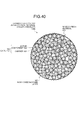
- a nano-carbon dense layer 107 including a nano-carbon material is produced on the apparent surface of a granulated catalyst 104B formed from aggregates of the catalyst 103.
- This nano-carbon dense layer 107 cannot be utilized as a nano-carbon material, which leads to the effective nano-carbon material yield decreasing.
- the catalyst-containing nano-carbon material 106 in which the nano-carbon material has grown from the catalyst has the feature of primary particles.
- Several of these primary particles gather together to form the granulated catalyst 104B, which is a nano-carbon material growth product.
- the carbon growth is very strong at the external surface due to maximum contact with the feed gas, the carbon becomes entangled, whereby this nano-carbon dense layer 107 is formed. It is strongly desired to increase the effective nano-carbon material yield and the carbon bulk density by untangling this nano-carbon dense layer 107.
- a nano-carbon material production apparatus includes: a nano-carbon material production unit for producing a nano-carbon material using a granulated catalyst formed by granulating a carrier supporting an active component; an acid treatment unit for dissolving and separating a catalyst by an acid solution by feeding a catalyst-containing nano-carbon material into the acid solution; and an anti-agglomeration treatment unit, which is provided on either or both of an upstream side and a downstream side of the acid treatment unit, for performing an anti-agglomeration treatment to prevent agglomeration among nano-carbons due to repulsion among oxygen-containing functional groups added to the nano-carbon material.
- the anti-agglomeration treatment unit is a pH adjustment unit, which is provided on a downstream side of a washing unit, which is for washing the acid-treated nano-carbon material with water, for adjusting a pH of a washed aqueous solution to a weakly alkaline side.
- the oxygen-containing functional groups dissociated on the alkaline side electrostatically repel each other, so that a distance between the nano-carbons widens, preventing agglomeration.
- the anti-agglomeration treatment unit is an oxygen-containing functional group addition treatment unit, which is provided on an upstream or the acid treatment unit, for adding an oxygen-containing functional group to the catalyst-containing nano-carbon material obtained by a nano-carbon production apparatus. Due to repulsion among the oxygen-containing functional groups, a distance between the nano-carbons widens, preventing agglomeration.
- the anti-agglomeration treatment unit is an oxygen-containing functional group addition treatment unit, which is provided on a downstream side of the acid treatment unit, for adding an oxygen-containing functional group to the nano-carbon material from which the catalyst has been removed. Due to repulsion among the added oxygen-containing functional groups, a distance between the nano-carbons widens, preventing agglomeration.
- the anti-agglomeration treatment unit includes two types of units.
- a first anti-agglomeration treatment unit is an oxygen-containing functional group addition treatment unit, which is provided on an upstream side of the acid treatment unit, for adding an oxygen-containing functional group to the catalyst-containing nano-carbon material obtained by a nano-carbon production apparatus. Due to repulsion among the added oxygen-containing functional groups, a distance between the nano-carbons widens, preventing agglomeration.
- a second anti-agglomeration treatment unit is a pH adjustment unit, which is provided after a washing unit for washing the acid-treated nano-carbon material with water, for adjusting a pH of a washed aqueous solution to a weakly alkaline side. Oxygen-containing functional groups dissociated on the alkaline side electrostatically repel each other, so that a distance between the nano-carbons widens, preventing agglomeration.
- the nano-carbon material production apparatus includes a quick-drying solvent displacement unit, which is provided on a downstream side of the washing unit, for displacing with a quick-drying solvent.
- the nano-carbon material production apparatus includes a quick-drying solvent displacement unit, which is provided on a downstream side of the washing unit, for displacing with a quick-drying solvent.
- the nano-carbon material production apparatus includes a quick-drying solvent displacement unit, which is provided on a downstream side of the washing unit, for displacing with a quick-drying solvent.
- a water-soluble dispersion and support agent for dispersing and supporting the nano-carbon material is fed to the acid treatment unit.
- a production apparatus for producing the catalyst-containing nano-carbon material is a fluidized bed reactor.
- the nano-carbon material production apparatus includes a fluidized catalyst feed apparatus for feeding a fluidized catalyst into the fluidized bed reactor.
- the fluidized catalyst has a particle size of 200 ⁇ m to 5 mm.
- the granulated catalyst formed by granulating the carrier supporting the active component is obtained from: a catalyst granulation unit for obtaining the granulated catalyst by granulating the carrier supporting the active component; and a granulated catalyst surface treatment unit for treating a surface of the granulated catalyst to decrease or reduce to zero a ratio of the active component on the surface present in at least an outermost layer of the granulated catalyst.
- an alkali adjustment chemical is any of ammonia and an amine.
- a method for producing a nano-carbon material includes: producing a nano-carbon material using a granulated catalyst formed by granulating a carrier supporting an active component; and at an earlier stage, a later stage, or an earlier and a later stage than an acid treatment, performing an anti-agglomeration treatment to prevent agglomeration among nano-carbons due to repulsion among oxygen-containing functional groups added to the nano-carbon material, the acid treatment performing an acid treatment by dispersing a catalyst-containing nano-carbon material in an acid solution.
- the anti-agglomeration treatment is a pH adjustment treatment, which is carried out at a later stage than a washing treatment for washing the acid-treated nano-carbon material with water, for adjusting a pH of a washed aqueous solution to a weakly alkaline side.
- Oxygen-containing functional groups dissociated on the alkaline side electrostatically repel each other, so that a distance between the nano-carbons widens, preventing agglomeration.
- the anti-agglomeration treatment is an oxygen-containing functional group addition treatment, which is carried out at an earlier stage than the acid treatment, for adding an oxygen-containing functional group to the catalyst-containing nano-carbon material obtained by a nano-carbon production apparatus. Due to repulsion among the added oxygen-containing functional groups, a distance between the nano-carbons widens, preventing agglomeration.
- the anti-agglomeration treatment is an oxygen-containing functional group addition treatment, which is carried out at a later stage than the acid treatment, for adding an oxygen-containing functional group to the nano-carbon material from which catalyst has been removed. Due to repulsion among the added oxygen-containing functional groups, a distance between the nano-carbons widens, preventing agglomeration.
- the anti-agglomeration treatment comprises two types of treatments.
- a first anti-agglomeration treatment is an oxygen-containing functional group addition treatment, which is carried out at an earlier stage than the acid treatment, for adding an oxygen-containing functional group to the catalyst-containing nano-carbon material obtained by a nano-carbon production apparatus. Due to repulsion among the added oxygen-containing functional groups, a distance between the nano-carbons widens, preventing agglomeration.
- a second anti-agglomeration treatment is a pH adjustment treatment, which is carried out at a later stage than a washing treatment for washing the acid-treated nano-carbon material with water, for adjusting a pH of a washed aqueous solution to a weakly alkaline side.
- Oxygen-containing functional groups dissociated on the alkaline side electrostatically repel each other, so that a distance between the nano-carbons widens, preventing agglomeration.
- the method for producing a nano-carbon material includes performing a quick-drying solvent displacement treatment, which is carried out at a later stage than the washing treatment, for displacing with a quick-drying solvent.
- the method for producing a nano-carbon material includes performing a quick-drying solvent displacement treatment, which is carried out at a last stage than the washing treatment, for displacing with a quick-drying solvent.
- the method for producing a nano-carbon material includes performing a quick-drying solvent displacement treatment, which is carried out at a last stage than the washing treatment, for displacing with a quick-drying solvent.
- the method for producing a nano-carbon material includes feeding a water-soluble dispersion and support agent for dispersing and supporting the nano-carbon material during the acid treatment.
- the method for producing a nano-carbon material includes the catalyst-containing nano-carbon material is produced by a fluidized bed reactor.
- the granulated catalyst formed by granulating the carrier supporting the active component is obtained by performing a granulated catalyst surface treatment for treating a surface of the granulated catalyst so that a ratio of the active component on the surface present in at least an outermost layer of the granulated catalyst is decreased or reduced to zero.
- an alkali adjustment chemical is any of ammonia and an amine.
- the present invention may also have the following configurations.
- a nano-carbon material production apparatus includes: a nano-carbon material production unit for producing a nano-carbon material using a catalyst granular material formed by granulating a carrier supporting an active component; an acid treatment unit for dissolving and separating a catalyst by an acid solution by feeding a catalyst-containing nano-carbon material into the acid solution; a crushing treatment unit, which is provided either on an upstream side of the acid treatment unit or in the acid treatment unit, for crushing a nano-carbon dense layer formed by aggregation of nano-carbon formed on a surface of a secondary particle formed from aggregation of catalyst primary particles which are the grown nano-carbon material; a washing unit, which is provided on a downstream side of the acid treatment unit, for washing the acid-treated nano-carbon material with water; and a drying unit for drying the nano-carbon material washed with water.
- a nano-carbon material production apparatus includes: a nano-carbon material production unit for producing a nano-carbon material using a catalyst granular material formed by granulating a carrier supporting an active component; an acid treatment unit for dissolving and separating a catalyst by an acid solution by feeding a catalyst-containing nano-carbon material into the acid solution; a washing unit for washing the acid-treated nano-carbon material with water; and a drying unit for drying the nano-carbon material washed with water, wherein a water-soluble dispersion and support agent for dispersing and supporting the nano-carbon material is fed to the acid treatment unit.
- a nano-carbon material production apparatus includes: a nano-carbon material production unit for producing a nano-carbon material using a catalyst granular material formed by granulating a carrier supporting an active component; a resin fixing treatment unit for fixing with a resin a periphery of a catalyst granular halving a nano-carbon dense layer formed by aggregation of nano-carbon formed on a surface of a secondary formed from aggregation of catalyst primary particles which are the grown nano-carbon a resin crushing treatment unit for crushing the resin fixing the nano-carbon dense layer by crushing the catalyst-containing granular material fixed by the resin along with the resin; an acid treatment unit for dissolving and separating the catalyst by an acid solution by feeding the catalyst-containing nano-carbon material the acid solution; a washing unit, which is provided on a downstream side of acid treatment unit, for washing the acid-treated nano-carbon material with and a drying unit for drying the nano-carbon material washed with water.
- a nano-carbon material production apparatus includes: a catalyst granulation unit for obtaining a granulated catalyst by granulating a carrier supporting an active component; a granulated catalyst surface treatment unit for treating a surface of the granulated catalyst to decrease or reduce to zero a ratio of the active component on the surface present in an outermost layer of the granulated catalyst; a nano-carbon material production unit for producing a nano-carbon material using the surface-treated granulated catalyst; an acid treatment unit for dissolving and separating the catalyst by an acid solution by feeding the catalyst-containing nano-carbon material into the acid solution; a washing unit, which is provided on a downstream side of the acid treatment unit, for washing the acid-treated nano-carbon material with water; and a drying unit for drying the nano-carbon material washed with water.
- a nano-carbon material production apparatus includes: a nano-carbon material production unit for producing a nano-carbon materials from a carbon raw material using a granulated catalyst formed by granulating a carrier supporting an active component; a combustion and removal substance addition unit for adding a substance for combustion and removal of nano-carbon around a catalyst granular material having a nano-carbon dense layer formed by aggregation of the nano-carbon formed on a surface of a secondary particle formed from aggregation of catalyst primary particles which are the grown nano-carbon materials; a combustion treatment unit for combusting a nano-carbon dense layer of the surface-treated catalyst granular material; an acid treatment unit for dissolving and separating the catalyst by an acid solution by feeding the combusted catalyst-containing material into the acid solution; a washing unit, which provided on a downstream side of the acid treatment unit, for washing the acid-treated nano-carbon material with water; and a drying unit for drying the nano-carbon material washed with water.
- a nano-carbon material is produced using a granulated catalyst formed by granulating a carrier which supports an active component. Agglomeration among the nano-carbon material is prevented by performing an anti-agglomeration treatment for preventing agglomeration among the nano-carbon material due to repulsion among oxygen-containing functional groups added to the nano-carbon material before and/or after performing an acid treatment by dispersing a catalyst-containing nano-carbon material in an acid solution.
- the nano-carbon material production apparatus includes a nano-carbon material production unit, an acid treatment unit, and an anti-agglomeration treatment unit.
- the nano-carbon material production unit produces a nano-carbon material using a granulated catalyst formed by granulating a carrier supporting an active component.
- the acid treatment unit feeds a catalyst-containing nano-carbon material into an acid solution, and dissolves and separates the catalyst by the acid solution.
- the anti-agglomeration treatment unit is provided on either or both of an upstream side and a downstream side of the acid treatment unit, and performs an anti-agglomeration treatment to improve hydrophilicity due to oxygen-containing functional groups added to the nano-carbon material and to prevent agglomeration among nano-carbons due to repulsion among oxygen-containing functional groups.
- This repulsion the oxygen-containing functional groups causes the gap between each of the entangled nano-carbons to widen, so that the tangles unravel. Additionally, the repulsion makes it more difficult for already unraveled nano-carbons to become entangled again.
- the oxygen-containing functional group include, as described below, a hydroxyl group (-OH), a carboxyl group (-COOH) and the like.
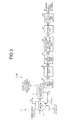
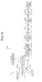
- Fig. 1 illustrates a schematic diagram of a nano-carbon material production apparatus according to the present embodiment for preventing tangling of carbon nanofibers by pH adjustment.
- a nano-carbon material production apparatus 10-1 according to this embodiment includes a nano-carbon material production unit 15, an acid treatment unit 21, a washing unit 22, a pH adjustment unit 23, a drying unit 24, and a heat treatment unit 25.
- the nano-carbon material production unit 15 produces a catalyst-containing nano-carbon material 14 by a fluidized bed reactor.
- the acid treatment unit 21 disperses the obtained catalyst-containing nano-carbon material 14 into an acid solution to dissolve and separate a fluidized catalyst 12, which is a granulated catalyst, by the acid solution.
- the washing unit 22 is provided on a downstream side of the acid treatment unit 21, and washes the acid-treated nano-carbon material with water.
- the pH adjustment unit 23 is provided on a downstream side of the washing unit 22, and adjusts the pH of the washed aqueous solution with a chemical to a weakly alkaline side.
- the drying unit 24 dries the nano-carbon material in a state in which the pH of the aqueous solution has been adjusted.
- the heat treatment unit 25 eliminates the chemical used for the alkaline adjustment by heat treatment to thereby produce a purified nano-carbon material 26.
- reference numeral 17 denotes a recovery apparatus for separating the catalyst-containing nano-carbon material 14 and the fluidized catalyst 12
- reference numeral 18 denotes a reuse line for reusing the separated fluidized catalyst 12 with a fluidized bed reactor 13
- reference numeral 19 denotes exhaust gas.
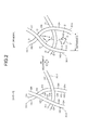
- Fig. 2 is a schematic diagram illustrating the behavior of nano-carbon due to pH adjustment.
- an oxygen-containing functional group such as a hydroxyl group (-OH) or a carboxyl group (-COOH)
- nano-carbons in the present embodiment, three strands
- an aqueous solution pH 5 to 6
- the pH is adjusted to the alkaline side of a pH of 7 or more (more preferably, to about pH 8 to 10) to dissociate the oxygen-containing functional group, such as a hydroxyl group (-OH) or a carboxyl group (-COOH), on the nano-carbons (in the present embodiment, three strands) 30-1 to 30-3.
- the oxygen-containing functional group such as a hydroxyl group (-OH) or a carboxyl group (-COOH
- These dissociated oxygen-containing functional groups electrostatically repel 31 each other, which causes the distance between the nano-carbons to widen, thereby preventing agglomeration.
- Fig. 2 although only -OH groups are schematically illustrated as the oxygen-containing functional group, the present invention is not limited to this.
- the nano-carbon material in which agglomeration was prevented is, as illustrated in Fig. 1 , dried by the drying unit 24, then sent to the heat treatment unit 25.
- the dried nano-carbon material is heat treated under a nitrogen atmosphere from 300 to 1,100°C for about 30 minutes to 2 hours, and preferably from 300 to 900°C for about 1 hour.
- the alkali adjustment chemical is eliminated, so that a purified nano-carbon material 26 free from agglomerations is obtained.
- Examples of the chemical used for pH adjustment in the present invention include amines such as ammonia and diethylamine, and alkali salts including a Group I element such as Na or K.
- amines such as ammonia and diethylamine
- alkali salts including a Group I element such as Na or K.
- any material that adjusts the pH to be weakly alkaline and is readily eliminated by a heat treatment may also be used.
- dispersion may be carried out using a stirring apparatus or an ultrasonic homogenizer, for example.
- a strong acid such as sulfuric acid, hydrochloric acid, nitric acid, aqua regia, and hydrofluoric acid.
- an auxiliary agent such as hydrogen peroxide may also be added.
- a surfactant may also be used to promote the dispersion effect.
- drying unit 24 in the present invention examples include, but are not especially limited to, in addition to drying by a common dryer, spray drying means, freeze frying means, and law-temperature spray freeze drying means.
- the nano-carbon material 31 is formed by growing from the active component 102 of the granulated catalyst 104A as illustrated in the above-described Fig. 38 .
- the granulated catalyst 104A may be formed from aggregates or agglomerations of catalyst primary particles of the carrier supporting the active component.
- the particle size of the granulated catalyst which is a secondary particle formed from such catalyst primary particles, is 200 ⁇ m to 5 mm, preferably 500 ⁇ m to 2,000 ⁇ m, and more preferably 500 ⁇ m to 1,000 ⁇ m.
- a product formed by granulating catalyst primary particles with a binder or a molded product formed by pressing catalyst primary particles with a pressing apparatus are obtained.
- size classification is carried out to obtain a product having a predetermined particle size.
- the specific surface area of the catalyst formed from the secondary particles from the perspective of improving the yield of the carbon material, 100 m 2 or more is preferred as the yield improves.
- the growth space of the carbon material is limited by the size of those pores, and especially by the ratio of (small pore diameter / large pore diameter) in the carrier.
- This growth space effects the tangle dispersibility of the carbon material.
- the pore capacity ratio of that pore system may be 20 or less, and preferably 10 or less. This is because if this ratio exceeds 20, the carbon material which grows on that carrier is strongly tangled, so that the tangle dispersibility deteriorates.
- the active component disperses into the carrier pores having a narrow diameter ( ⁇ ), and the nano-carbon material grows from this active component.
- the nano-carbon material becomes entangled during its growth.
- Such a tangled nano-carbon material will not have, for example, good dispersibility in a solution, a resin and the like.
- the active component disperses at flat locations of the carrier, and the nano-carbon material grows from this active component.
- the ratio of nano-carbon material which entirely grows straight increases. Consequently, the dispersibility in a solution, a resin and the like of such a nano-carbon material is favorable.
- the above ratio may be 5 or less, preferably 3 or less, and more preferably 1 or less.
- the above ratio may be 10 or less, preferably or less, and more preferably 3 or less.
- the pores are relatively larger at 50 nm and 100 nm, which is preferred because the dispersibility increases.
- the above small pore diameter is 30 nm or less, and preferably in the range of 0.1 to 30 nm.
- the above large pore diameter is 30 nm or more, and preferably in the range of 30 to 200 nm. If the small and large pore diameters are thus set, the ratio thereof may be 20 or less, and preferably 10 or less.
- the determination regarding large and small does not have to be based on 30 nm as a demarcation. For example, the determination may be 20 nm, 15 nm, or 10 nm as a demarcation for determining large and small.
- the nano-carbon material according to the present invention is not a stand-alone material, and that a ratio of bundled carbon material present in a multiply-bundled state is 1 to 95%, and more preferably 1 to 80%.
- bundled carbon refers to a collection of two or more strands of the carbon material, and includes cases in which a few strands are collected to cases in which many strands are collected.
- the structure of the nano-carbon material according to the present invention is preferably any of fibrous, granular, and tubular.
- granular refers to a structure formed by crystallites composed of graphite layers composed of a material formed from a single carbon hexagonal plane aggregating.
- the "fibrous structure” is any of: a structure in which carbon hexagonal planes are laminated and the lamination method thereof is along a fiber axis; a structure in which an oblique direction (1 to 89°) of a so-called platelet laminate is the fiber axis; a so-called herringbone or fishbone structure; a structure having a fiber axis perpendicular to the lamination direction; and a so-called tubular, ribbon, or parallel structure.
- the slants of the herringbone structure are formed as a pair. The slants in this pair do not have to have the same incline.
- the carbon material according to the present invention preferably has a tubular shape, and the tube walls are preferably a single-walled structure or a double-wall structure.
- the concentration thereof is preferably 20 to 99%, and more preferably 85 to 99%.
- the concentration of single walls and double walls combined is preferably 20 to 99%, and more preferably 75 to 99%.
- the tubular shape preferably has a ratio of carbon hexagonal planes of 1.3 to 30%, and more preferably 1.3 to 15%.
- the nano-carbon material has a diameter of preferably 0.4 nm or more, more preferably 0.4 to 3.5 nm, and still more preferably 1.5 to 3.5 nm. Furthermore, it is preferred that the ratio having a diameter of 1.5 to 3.5 nm is 85%.
- Examples of the above-described active component in the present invention include, but are not limited to, any one kind of V, Cr, Mn, Fe, Co, Ni, Cu, Zn, W, Mo, or a combination thereof.
- Examples of the above-described carrier in the present invention include, but are not limited to, aluminum compounds such as alumina, silica, sodium aluminate, alum, and aluminum phosphate, calcium compounds such as calcium oxide, calcium carbonate, and calcium sulfate, magnesium compounds such as magnesium oxide, magnesium hydroxide, and magnesium sulfate, and apatites such as calcium phosphate and magnesium phosphate.
- the carrier may include two or more kinds of these compounds.
- apatite is a mineral having a M 10 2+ (Z 5- O 4 ) 6 X 2 - structure, in which one or two kinds or more of the following various elements are present in solid state as M, ZO 4 , and X.
- ZO 4 PO 4 , AsO 4 , VO 4 , SO 4 , SiO 4 , CO 4 X: F, OH, Cl, Br, O, I
- a mesoporous material such as talc (MgAl 2 O 3 ), other minerals, zeolite, and mesoporous silicate may also be used.
- a diffusion layer including both the active component and the carrier may be formed on the surface of the carrier due to the interaction between them, and the diffusion layer may cover a portion of the active component catalyst to miniaturize the exposed portions of the active component catalyst.
- the nano-carbon material since the nano-carbon material only grows from the miniaturized active component portion, only a single-walled nano-carbon material can be produced well.
- Fig. 3 illustrates a schematic diagram of another nano-carbon material production apparatus according to the first embodiment for preventing tangling of carbon nanofibers by pH adjustment.
- a nano-carbon material production apparatus 10-1B according to the present embodiment is further provided with a quick-drying solvent displacement unit 28 on the downstream side of the pH adjustment unit 23 in the nano-carbon material production apparatus 10-1A.
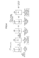
- Fig. 4 illustrates a schematic diagram of the step of quick-drying solvent displacement in the quick-drying solvent displacement unit.
- a nano-carbon material 32 from which the catalyst has been removed is floating in a washing solution 33 in a water tank which was subjected to a washing treatment with water by a washing unit 22.
- this washing solution (50 mL) 33 the same amount (50 mL) of an alcohol (for example, ethanol) is added to obtain a first mixed solution 35.
- This first mixed solution 34 consists of 50% alcohol and 50% water.
- this first mixed solution 35 is filtered and concentrated by a means such as centrifugal separation to obtain a total amount of 50 mL of a concentrated first mixed solution 36.
- 50 mL of acetone, which is a quick-drying solvent 37 is added to the concentrated first mixed solution 36 to obtain a second mixed solution 38.
- This second mixed solution 38 consists of 25% alcohol, 25% water, and 50% acetone. Since about 50% of this second mixed solution 38 is replaced by acetone, which is the quick-drying solvent 37, the drying rate at the subsequent drying unit 24 improves, so that agglomeration among the nano-carbon material is prevented.
- the solvent used by the quick-drying solvent displacement unit 28 lower alcohols such as ethanol, methanol, and isopropyl alcohol, acetone, or hexane are especially preferred. Furthermore, it is preferred that the displacement ratio from the water is at least 50%. This is because if the displacement ratio is less than 50%, the effect of suppressing condensing of the nano-carbon material during the drying by the drying unit 24 is not exhibited. Thus, by providing the quick-drying solvent displacement unit 28, about 50% of the second mixed solution 38 is replaced by acetone, which is a quick-drying solvent 37, so that the drying rate at the subsequent drying unit 24 improves, and agglomeration among the nano-carbon material is further prevented.
- acetone which is a quick-drying solvent 37
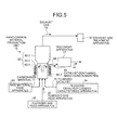
- Fig. 5 is a schematic diagram of a nano-carbon material production unit.
- a catalyst for nano-carbon material production formed from secondary particles having a predetermined particle size obtained by consolidation of catalyst primary particles formed from a carrier (magnesium oxide) supporting an active component (iron) is used as a fluidized catalyst 61 that combines both a catalytic activity and a flow behavior.
- a nano-carbon material production unit 15 includes a fluidized bed reaction unit 62-1, a raw material feed apparatus 63, a fluidized catalyst feed apparatus 64, a freeboard unit 62-2, a fluidized gas feed apparatus 66, a heating unit 62-3, an exhaust gas treatment apparatus 67, and a recovery apparatus 17.
- the fluidized bed reaction unit 62-1 is filled in its interior with a fluidized catalyst 61, which acts both as a catalyst and as a fluidized material.
- the raw material feed apparatus 63 feeds a carbon raw material 11, which is a carbon source, into the fluidized bed reaction unit 62-1.
- the fluidized catalyst feed apparatus 64 feeds the fluidized catalyst 61 into the fluidized bed reaction unit 62-1.
- the freeboard unit 62-2 has a space into which the fluidized catalyst 61, being the fluidized material in the fluidized bed reaction unit 62-1, scatters and flows.
- the fluidized gas feed apparatus 66 introduces a fluidized gas 65 into the fluidized bed reaction unit 62-1 and causes the fluidized catalyst 61 therein to flow.
- the heating unit 62-3 heats the fluidized bed reaction unit 62-1.
- the exhaust gas treatment apparatus 67 treats an exhaust gas 19 exhausted from the freeboard unit 62-2.
- the recovery apparatus 17 extracts the catalyst-containing nano-carbon material 14 from the fluidized bed reaction unit 62-1 in a recovery line 68 for recovery.
- Examples of fluidized bed reaction modes in the fluidized bed reaction unit 62-1 include a bubbling fluidized bed type and a jet fluidized bed type. In the present invention, either of these may be used.
- a fluidized bed reactor 62 is configured from the fluidized bed reaction unit 62-1, the freeboard unit 62-2, and the heating unit 62-3. Furthermore, it is preferred that the freeboard unit 62-2 has a larger flow path cross-sectional area than the fluidized bed reaction unit 62-1.
- the carbon material 11, which is the raw material gas fed from the raw material feed apparatus 63, may be any compound containing carbon.
- Examples thereof in the present invention include, but are not limited to, in addition to CO and CO 2 , alkanes such as methane, ethane, hexane, and propane, unsaturated organic compounds such as ethylene, propylene, and acetylene, aromatic compounds such as benzene and toluene, organic compounds having an oxygen-containing functional group such as alcohols, ethers, and carboxylic acids, polymer materials such as polyethylene and polypropylene, or oil and coal (including coal converted gas).
- an oxygen-containing carbon source such as CO, CO 2 , an alcohol, an ether, and a carboxylic acid, and a non-oxygen-containing carbon source may be combined and fed.
- This carbon material 11 is fed in a gaseous state into the fluidized bed reaction unit 62-1, where a uniform reaction occurs due to the fluidized catalyst 61, which is a fluidized material, under stirring to cause a nano-carbon material to grow.
- an inert gas is introduced as a separate fluidized gas 65 into the fluidized bed reaction unit 62-1 by the fluidized gas feed apparatus 66.
- the temperature in the fluidized bed reaction unit 62-1 is set by the heating unit 62-3 to a range of 300 to 1,300°C, and more preferably 400 to 1,200°C.
- the carbon material 11, such as methane, is brought into contact with the catalyst for a fixed period of time in an environment in which an impurity carbon degradation product is also present to produce the nano-carbon material.
- Examples of apparatuses which can be used as the above-described recovery apparatus 17 include, in addition to a cyclone, known separation means such a bag filter, a ceramic filter, and a sieve.
- the catalyst-containing nano-carbon material 14 separated by the recovery apparatus 17 is, as described above, recovered as a nano-scale purified nano-carbon material (for example, as a carbon nanotube, a carbon nanofiber etc.) 26 free from agglomerations, by removing the catalyst adhered to the nano-carbon material with the acid treatment unit 21, washing unit 22, pH adjustment unit 23, and drying unit 24. Furthermore, by providing the quick-drying solvent displacement unit 28 on the downstream side of the pH adjustment unit 23, a nano-scale purified nano-carbon material (for example, a carbon nanotube, a carbon nanofiber etc.) 26 having even less agglomerations can be recovered.
- a nano-scale purified nano-carbon material for example, a carbon nanotube, a carbon nanofiber etc.
- Fig. 6 illustrates a schematic diagram of a nano-carbon material production apparatus according to a second embodiment for performing an addition treatment of an oxygen-containing functional group.
- Fig. 7 is a schematic diagram illustrating nano-carbon behavior due to repulsion among oxygen-containing functional groups.
- a nano-carbon material production apparatus 10-2A according to the second embodiment includes a nano-carbon material production unit 15, an oxygen-containing functional group addition treatment unit 27, an acid treatment unit 21, a washing unit 22, and a drying unit 24.
- the nano-carbon material production unit 15 produces a catalyst-containing nano-carbon material 14 by a fluidized bed reactor 13.
- the oxygen-containing functional group addition treatment unit 27 adds an oxygen-containing functional group to the obtained catalyst-containing nano-carbon material 14.
- the acid treatment unit 21 dissolves and separates a fluidized catalyst 12, which is a granulated catalyst, by an acid solution by dispersing in the acid solution the catalyst-containing nano-carbon material 14 to which an oxygen-containing functional group was added.
- the washing unit 22 washes the acid-treated nano-carbon material with water.
- the drying unit 24 dries the washed nano-carbon material to produce a purified nano-carbon material 26.
- the oxygen-containing functional group addition treatment unit 27 is not especially limited, as long as it is means for adding, or causing to be added, an oxygen-containing functional group onto the surface of the nano-carbon material. Either or both of a physical treatment and a chemical treatment may be used to carry this out.
- Examples of physical treatments include, under an oxygen atmosphere, a heat treatment, a steam oxidation treatment, a plasma treatment, a sputtering treatment, or a discharge treatment such as glow discharge, arc discharge, corona discharge, and streamer discharge.
- the oxygen-containing functional group is added, or caused to be added, onto the surface of the nano-carbon material by carrying out any one or a combination of these.
- examples of chemical treatments include a polymer grafting treatment carried out using a polymer and the like, a surface modification reaction treatment carried out by an oxidation treatment, and a surfactant treatment.
- the oxygen-containing functional group is added, or caused to be added, onto the surface of the nano-carbon material by carrying out any one or a combination of these.
- oxidation treatment examples include oxidation treatments carried out using a strong acid, such as sulfuric acid and hydrochloric acid.
- a strong acid such as sulfuric acid and hydrochloric acid.
- the addition of the oxygen-containing functional group and the dissolving and separation by the acid solution of the fluidized catalyst 12, which is a granulated catalyst may also be carried out in a single process. More specifically, although an acid treatment tank for the addition of the oxygen-containing functional group may be separately and independently provided, the oxygen-containing functional group addition treatment and the catalyst removal treatment may also be carried out simultaneously in the acid treatment tank for catalyst removal.
- any of an anionic surfactant, a cationic surfactant, an amphoteric surfactant, and a nonionic surfactant may be used.
- examples include inorganic acid esters, cyclic ethers, carboxylic acid anhydrides, dicarboxylic acids, aliphatic carboxylic acids, unsaturated carboxylic acids, alicyclic ketones, alicyclic alcohols, aliphatic alcohols, aliphatic chlorinated compounds, aliphatic amines, aliphatic nitriles, unsaturated fatty acids, carboamides, aromatic polyamides, azo compounds, pyrene functionalized block copolymers, cellulose derivatives, long chain benzenediazonium, glucose oxidase, alicyclic nitrile compounds, quinoid compounds, polyols, diols, diamines, dienes and the like.
- Fig. 7 how the oxygen-containing functional group is added to the nano-carbon material constituting the dense layer and how the nano-carbons unravel will be described.
- the nano-carbon material still has the catalyst adhered to it (this catalyst is formed from the active component and the carrier), the catalyst will not be illustrated in the drawings.
- nano-carbons 31-1 to 31-3 (in the present embodiment, there are three strands) constituting the dense layer are entangled in a complex manner (refer to the diagram on the left side of Fig. 7 ).
- the nano-carbons 31-1 to 31-3 constituting the carbon dense layer are treated by the oxygen-containing functional group addition treatment unit 27, whereby an oxygen-containing functional group (for example, -OH) is added to the surface of the nano-carbons 31-1 to 31-3 (refer to the center diagram of Fig. 7 ).
- an oxygen-containing functional group for example, -OH
- the oxygen ratio is increased. Therefore, due to the addition of an oxygen-containing functional group carried out in the present invention, the number of oxygens increases. Consequently, the nano-carbon material according to the present invention has an O (number of oxygens in an atomic state) / C (number of carbons in an atomic state) ratio of 0.01 to 0.2, preferably 0.02 to 0.1, and more preferably 0.02 to 0.08.
- the reason why the O (number of oxygens in an atomic state) / C (number of carbons in an atomic state) ratio is set at 0.01 to 0.2 is that if the number of oxygens in an atomic state is increased by excessively carrying out the oxygen-containing functional group treatment, defects are produced on the surface of the nano-carbon material, and the nano-carbon material is cut, which are not desirable.
- the nano-carbon material becomes hydrophilic, so that the composite effect of preventing subsequent agglomeration when the nano-carbon material comes into contact with moisture in the acid treatment unit 21 can be exhibited.
- the oxygen-containing functional group addition treatment unit 27 may be provided on the downstream side of the acid treatment unit 21, like the nano-carbon material production apparatus 10-2B illustrated in Fig. 8 , to carry out the oxygen-containing functional group addition treatment.
- the oxygen-containing functional group addition treatment unit 27 may be provided on the downstream side of the washing unit 22, like the nano-carbon material production apparatus 10-2C illustrated in Fig. 9 , to carry out the oxygen-containing functional group addition treatment.
- the oxygen-containing functional group addition treatment unit 27 is provided on the downstream side of the acid treatment unit 21, the catalyst is removed with an acid by the acid treatment unit 21. Therefore, rather than the oxygen-containing functional group being added to the catalyst-containing nano-carbon material, the oxygen-containing functional group is added to a nano-carbon material from which the catalyst has been removed. However, if some of the catalyst has not been removed, this corresponds to the oxygen-containing functional group being added to the catalyst-containing nano-carbon material.
- the nano-carbon material becomes hydrophilic, so that subsequent agglomeration when the nano-carbon material comes into contact with moisture in the washing unit 22 is prevented. Therefore, as illustrated in Fig. 8 , it is preferred to carry out the oxygen-containing functional group addition treatment at a stage prior to the washing treatment.
- a pH adjustment unit 23 is further added to the nano-carbon material production apparatus 10-2A illustrated in Fig. 6 , to cause the oxygen-containing functional groups on the alkaline side to dissociate.
- the electrostatic repulsion 31 produced by the dissociated oxygen-containing functional groups causes the distance between the nano-carbons to widen, thereby preventing agglomeration. Consequently, dissociation of the oxygen-containing functional groups added in the acid treatment proceeds further, resulting in the electrostatic repulsive force strengthening. As a result, the synergetic effect that the level of repulsion improves is exhibited.
- the oxygen-containing functional group addition treatment unit 27 may be provided further on the downstream side of the pH adjustment unit 23 in the above-described nano-carbon material production apparatus 10-1A illustrated in Fig. 1 according to the first embodiment for preventing tangling of the carbon nanofibers by pH adjustment.
- the dissociated oxygen-containing functional groups electrostatically repel each other, causing the distance between the nano-carbons to widen, thereby preventing agglomeration.
- the dissociation effect is increased.
- the drying treatment is carried out with the drying unit 24, and agglomeration in the subsequent step of removing the alkali agent with the heat treatment unit 25 is prevented.
- Fig. 12 illustrates a schematic diagram of a nano-carbon material production apparatus according to a third embodiment for performing a displacement treatment with a quick-drying solvent.
- a nano-carbon material production apparatus 10-3A according to the third embodiment includes a nano-carbon material production unit 15, an acid treatment unit 21, a unit 22, a quick-drying solvent displacement unit 28, and a drying unit 24.
- the nano-carbon material production unit 15 produces a catalyst-containing nano-carbon material 14 by a fluidized bed reactor 13.
- the acid treatment unit 21 dissolves and separates a fluidized catalyst 12, which is a granulated catalyst, by an acid solution by dispersing the obtained catalyst-containing nano-carbon material 14 in the acid solution.
- the washing unit 22 is provided on the downstream side of the acid treatment unit 21, and washes the acid-treated nano-carbon material with water.
- the quick-drying solvent displacement unit 28 is provided on the downstream side of the washing unit 22, and displaces with a quick-drying solvent.
- the drying unit 24 dries the nano-carbon material displaced with the quick-drying solvent to produce a purified nano-carbon material 26. Consequently, the drying rate at the subsequent drying unit 24 improves, so that agglomeration among the nano-carbon material may be prevented.
- the quick-drying solvent displacement unit 28 may be provided on the downstream side of the washing unit 22 in the nano-carbon material production apparatus 10-2A illustrated in Fig. 6 , so that the drying rate at the subsequent drying unit 24 improves and agglomeration among the nano-carbon material is also prevented.
- the quick-drying solvent displacement unit 28 may be provided on the downstream side of the washing unit 22 in the nano-carbon material production apparatus 10-2B illustrated in Fig. 8 , so that the drying rate at the subsequent drying unit 24 improves and agglomeration among the nano-carbon material is also prevented.
- the quick-drying solvent displacement unit 28 may be provided on the downstream side of the oxygen-containing functional group addition treatment unit 27 in the nano-carbon material production apparatus 10-2C illustrated in Fig. 9 , so that the drying rate at the subsequent drying unit 24 improves and agglomeration among the nano-carbon material is also prevented.
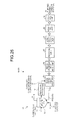
- Fig. 16 is a schematic diagram of a nano-carbon material production apparatus according to a fourth embodiment for feeding a water-soluble dispersion and support agent in an oxygen treatment.
- Fig. 17 is a schematic diagram of an acid treatment using a water-soluble dispersion and support agent.
- a nano-carbon material production apparatus 10-4A according to the fourth embodiment includes: a nano-carbon material unit 15 for producing a nano-carbon material 14 by a fluidized bed reactor 13; and an acid treatment unit 21 for dissolving and separating a fluidized catalyst 12, which is a granulated catalyst, by an acid solution by dispersing the obtained catalyst-containing nano-carbon material 14 in the acid solution.
- a water-soluble dispersion and support agent 41 is fed by the acid treatment unit 21.
- This water-soluble dispersion and support agent 41 disperses and supports the nano-carbon material to suppress agglomeration among the nano-carbon material isolated from the active metal component by the acid. Subsequently, the agglomeration-suppressed nano-carbon material is washed by the washing unit 22 with water, and then dried by the drying unit 24. The water-soluble dispersion and support agent 41 is then heat treated at a high temperature (for example, 700 to 1,100°C) in the heat treatment unit 25 to carry out pyrolysis and removal, whereby a purified nano-carbon material 26 is obtained.
- a high temperature for example, 700 to 1,100°C
- the water-soluble dispersion and support agent 41 added into the acid treatment unit 21 supports that nano-carbon material. More specifically, for the catalyst-containing nano-carbon material 14 fed into an acid solution, the active component and the carrier, which constitute the catalyst, are dissolved by the acid in the acid treatment unit 21 to form an isolated nano-carbon material which floats in the acid solution. During this process, as illustrated in Fig. 17 , if the water-soluble dispersion and support agent 41 dissolved in an acid solution is present, the water-soluble dispersion and support agent 41 intercalates among the purified nano-carbon material 26.
- the water-soluble dispersion and support agent 41 a material having both a hydrophobic group, which easily associates with the hydrophobic group of the nano-carbon material, and a hydrophilic group. Therefore, it is preferred to use one of a resin compound, a surfactant, a polysaccharide, and an anti-agglomeration agent having these properties or a combination thereof. Furthermore, optionally, a dispersion auxiliary may also be added.
- the resin compound examples include polyethylene glycol (PEG), polyethylene oxide (PEO), and polycarbonate (PC). It is especially preferred to use an equivalent resin, or a resin having similar properties, to the resin used in the product in which the nano-carbon material will be dispersed, because there is no need to eliminate the resin compound.
- PEG polyethylene glycol
- PEO polyethylene oxide
- PC polycarbonate
- any of an anionic surfactant, a cationic surfactant, an amphoteric surfactant, and a nonionic surfactant may be used.
- examples include inorganic acid esters, cyclic ethers, carboxylic acid anhydrides, dicarboxylic acids, aliphatic carboxylic acids, unsaturated carboxylic acids, alicyclic ketones, alicyclic alcohols, aliphatic alcohols, aliphatic chlorinated compounds, aliphatic amines, aliphatic nitriles, unsaturated fatty acids, carboamides, aromatic polyamides, azo compounds, pyrene functionalized block copolymers, cellulose derivatives, long chain benzenediazonium, glucose oxidase, alicyclic nitrile compounds, quinoid compounds, polyols, diols, diamines, dienes and the like.
- polysaccharide examples include xanthan gum, starch, amylose, amylopectin, glycogen, cellulose, chitin, agarose, carrageenan, heparin, hyaluronic acid, pectin, and xyloglucan.
- anti-agglomeration agent examples include polyaniline sulfonic acid (PAS).
- Fig. 18 illustrates a schematic diagram of another nano-carbon material production apparatus according to the present embodiment.
- a nano-carbon material production apparatus 10-4B according to the present embodiment further has the oxygen-containing functional group addition treatment unit 27 for adding an oxygen-containing functional group to the obtained catalyst-containing nano-carbon material 14 on the upstream side of the acid treatment unit 21 in the nano-carbon material production apparatus 10-4A illustrated in Fig. 16 .
- the oxygen-containing functional group addition treatment unit 27 is not especially limited, as long as it is means for adding, or causing to be added, an oxygen-containing functional group onto the surface of the nano-carbon material. Either or both of the above-described physical treatments and chemical treatments may be used to carry this out.
- Fig. 19 is a schematic diagram of a nano-carbon material production apparatus according to a fifth embodiment for performing a crushing treatment before an acid treatment.
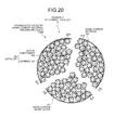
- Fig. 20 is a schematic diagram illustrating crushing of a catalyst granular material formed of secondary particles.
- a nano-carbon material production apparatus 10-5A according to the fifth embodiment includes a nano-carbon material production unit 15, an acid treatment unit 21, a crushing treatment unit 51, a washing unit 22, and a drying unit 24.
- the nano-carbon material production unit 15 produces a catalyst-containing nano-carbon material 14 by a fluidized bed reactor 13.
- the acid treatment unit 21 dissolves and separates a fluidized catalyst 12, which is a granulated catalyst, by an acid solution by dispersing the obtained catalyst-containing nano-carbon material 14 in the acid solution.
- the crushing treatment unit 51 is provided on the upstream side of the acid treatment unit 21, and crushes a nano-carbon dense layer formed by aggregation of the nano-carbon formed on the surface of a secondary particle formed from aggregation of catalyst primary particles which are the growth nano-carbon material.
- the washing unit 22 is provided on the downstream side of the acid treatment unit 21, and washes the acid-treated nano-carbon material with water.
- the drying unit 24 dries the washed nano-carbon material.
- the crushing treatment unit 51 by providing the crushing treatment unit 51, the nano-carbon dense layer 107 (refer to Fig. 40 ) formed on the surface of the secondary particles, which are the granulated catalyst 104B, is crushed. Consequently, the catalyst primary particles which are the grown nano-carbon material 105 present in the interior and which are derived from the broken up crushing treatment product 52 are well dispersed. As a result, the yield of effective nano-carbon can be improved and the carbon bulk density can be reduced.
- the crushing treatment unit 51 is provided on the upstream side of the acid treatment unit 21, the crushing treatment may also be carried out simultaneously with the treatment in the acid treatment unit 21.
- the crushing treatment unit 51 adds a shearing or a crushing action on the granulated catalyst before or during the acid treatment, so that the nano-carbon dense layer agglomerated on the catalyst surface can be effectively crushed.
- Examples of the crushing treatment unit 51 include a ball mill, a high shear stirrer (for example, "T.K. Homomixer” (trade name, manufactured by Primix Corporation), "Ultra-Turrax” (trade name, manufactured by IKA Japan K.K.)) and the like.
- a ball mill for example, "T.K. Homomixer” (trade name, manufactured by Primix Corporation), "Ultra-Turrax” (trade name, manufactured by IKA Japan K.K.)) and the like.
- an impurity removal unit can be provided so that only effective nano-carbon material is obtained.
- This impurity unit may use various separation means, such as centrifugal separation means, sieve means, electrophoretic means, and air classification means.
- Fig. 21 illustrates a schematic diagram of another nano-carbon material production apparatus according to a fifth embodiment for performing a crushing treatment before an acid treatment.
- a nano-carbon material production apparatus 10-5B according to the present embodiment is further provided with a pH adjustment unit 23 on the downstream side of the washing unit 22, in the nano-carbon material production apparatus 10-5A illustrated in Fig. 19 .
- the pH adjustment causes the oxygen-containing functional groups, such as a hydroxyl group (-OH) or a carboxyl group (-COOH), of the nano-carbon to dissociate.
- These dissociated oxygen-containing functional groups electrostatically repel 31 each other, which causes the distance between the nano-carbons to widen, whereby agglomeration can be prevented.
- Fig. 22 illustrates a schematic diagram of another nano-carbon material production apparatus according to the fifth embodiment for performing a crushing treatment before an acid treatment.
- a nano-carbon material production apparatus 10-5C according to the fifth embodiment is provided with a quick-drying solvent displacement unit 28 on the downstream side of the pH adjustment unit 23, in the nano-carbon material production apparatus 10-5B illustrated in Fig. 21 . Consequently, by displacing with, for example, acetone, which is a quick-drying solvent, the drying rate at the subsequent drying unit 24 improves, so that agglomeration among the nano-carbon material is further prevented.
- acetone which is a quick-drying solvent
- Fig. 23 illustrates a schematic diagram of a nano-carbon material production apparatus according to a sixth embodiment for performing a crushing treatment using a resin before an acid treatment.
- Fig. 24 is a schematic diagram illustrating crushing of a catalyst granular material, formed of secondary particles, by a resin.
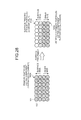
- Fig. 25 is a schematic diagram illustrating the crushing of a single unit of a catalyst granular formed of secondary particles, along with a resin.
- a nano-carbon material production apparatus 10-6A according to the sixth embodiment includes a nano-carbon material production unit 15, a resin fixing treatment unit 53, a resin crushing treatment unit 54, an acid treatment unit 21, a washing unit 22, and a drying unit 24.
- the nano-carbon material production unit 15 produces a catalyst-containing nano-carbon material 14 by a fluidized bed reactor 13.
- the resin fixing treatment unit 53 fixes with a resin the periphery of a granulated catalyst having a nano-carbon dense layer formed by aggregation of the nano-carbon formed on the surface of a secondary particle formed from aggregation of catalyst primary particles which are the growth nano-carbon material.
- the resin crushing treatment unit 54 crushes the resin fixing the nano-carbon dense layer by crushing the catalyst-containing granular material fixed by the resin along with the resin.
- the acid treatment unit 21 dissolves and separates a catalyst by an acid solution by feeding the catalyst-containing nano-carbon material 14 crushed along with the resin into the acid solution.
- the washing unit 22 is provided on the downstream side of the acid treatment unit 21, and washes the acid-treated nano-carbon material with water.
- the drying unit 24 dries the washed nano-carbon material.
- the nano-carbon dense layer is formed on the surface of secondary particles, when fixed with a resin the nano-carbon dense layer is fixed preferentially to the nano-carbon or carbon nanotubes having excellent dispersibility which have grown in the interior of the secondary particles.
- Fig. 24 is a schematic diagram illustrating the fixing of a granulated catalyst by the resin. However, in actual fact, countless granulated catalyst particles are fixed by the resin.
- the periphery of the granulated catalyst 104B is fixed by a resin for a single unit of the granulated catalyst 104B. Subsequently, in the crushing treatment, this granulated catalyst 104B is turned into the resin crushing treatment product 56 broken into many pieces. Thus, the catalyst primary particles which are the grown nano-carbon material 105 present in the interior of the crushed piece 56a are well dispersed.
- the fixing resin examples include an epoxy resin, polycarbonate, polyethylene, polypropylene, polyurethane, polyester, polystyrene, a urea resin, a phenol resin, and a vinyl resin. It is especially preferred to use an equivalent resin, or a resin having similar properties, to the resin used in the product in which the nano-carbon material will be dispersed, because there is no need to eliminate or remove the resin compound.
- a weakening agent for weakening the resin may be pre-added to the resin to make the resin more brittle, thereby facilitating crushing.
- the weakening agent include sand, silica, silica sand, and alumina. Since the weakening agent becomes an impurity, it is preferred to add as little an amount as possible.
- examples of the resin crushing treatment unit 54 include a ball mill, a high shear stirrer (for example, "T.K. Homomixer” (trade name, manufactured by Primix Corporation), "Ultra-Turrax” (trade name, manufactured by IKA Japan K.K.)) and the like.
- a removal unit 57 for removing the nano-carbon dense layer fixed to the crushed resin may be provided on the downstream side of the resin crushing treatment unit 54 so that only effective nano-carbon material is obtained.
- the removal unit 57 may also be provided on the downstream side of the drying unit 24.
- Examples of the removal unit 57 include various separation and removal means, such as centrifugal separation means, sieve means, electrophoretic means, and air classification means. During this process, in addition to removal of pieces of simultaneously crushed resin, the nano-carbon dense layer fixed to the resin is also removed along with the resin pieces.
- Fig. 27 illustrates a schematic diagram of a nano-carbon material production apparatus according to a seventh embodiment for performing a pre-treatment on a granulated catalyst.
- Fig. 28 is a schematic diagram of a pre-treatment state of the granulated catalyst.
- Fig. 29 is a schematic diagram of surface treatment of the outermost layer of a secondary particle.
- Fig. 30 is a schematic diagram of another surface treatment apparatus for a secondary particle outermost layer.
- a nano-carbon material production apparatus 10-7A according to the present embodiment includes a catalyst granulation unit 71, a granulated catalyst surface treatment unit 72, a nano-carbon material production unit 15, an acid treatment unit 21, a washing unit 22, and a drying unit 24.
- the catalyst granulation unit 71 obtains a granulated catalyst by granulating a carrier supporting an active component.
- the granulated catalyst surface treatment unit 72 treats the surface of the granulated catalyst to decrease or reduce to zero the ratio of active component on the surface of the primary particles present in the outermost layer of the granulated catalyst.
- the nano-carbon material production unit 15 produces a catalyst-containing nano-carbon material 14 by a fluidized bed reactor 13 using a surface-treated fluidized catalyst 12.
- the acid treatment unit 21 dissolves and separates a catalyst by an acid solution by feeding the catalyst-containing nano-carbon material 14 into the acid solution.
- the washing unit 22 is provided on the downstream side of the acid treatment unit 21, and washes the acid-treated nano-carbon material with water.
- the drying unit 24 dries the washed nano-carbon material.
- the granulated catalyst according to the present invention is produced by treating the surface of the obtained granulated catalyst so that the ratio of active component present in at least the outermost layer of the granulated catalyst is reduced or zero.
- FIG. 28 is a schematic diagram of a granulated catalyst in a pre-treatment state, in which the primary particles have aggregated near the surface. Furthermore, in Fig. 28 , the "surface side” is the surface side of the secondary particles, and the “inner side” is the center side of the secondary particles.
- surface-treated primary particles 103B are present, which inhibit the growth of the nano-carbon material. Furthermore, untreated primary particles 103A are present on the inner side, so that the nano-carbon material grows from the active component in the same manner as conventionally. As a result, formation of the nano-carbon dense layer 107 as illustrated in Fig. 40 around the catalyst granular material 107B is suppressed.
- the washing treatment by the granulated catalyst surface treatment unit 72 is carried out by dipping a wire cage 112, in which secondary particles 100 are placed, in a water tank 110, and cleaning with cleaning water 111 to remove the active component supported on the carrier.
- a reaction inhibiting substance such as an alkali metal salt of Na, K and the like (potassium carbonate, sodium carbonate etc.) or an alkaline earth metal salt such as a Mg salt (magnesium carbonate etc.), may be supported on the surface of the primary particles.
- an alkali metal salt of Na, K and the like potassium carbonate, sodium carbonate etc.
- an alkaline earth metal salt such as a Mg salt (magnesium carbonate etc.
- an inert substance such as alumina may also be supported.
- this alkali metal salt and the like undergoes catalytic combustion and gasification, thereby inhibiting the growth of the nano-carbon material (CNT) on the surface side of a secondary particle. Consequently, there is no or very short growth of the nano-carbon material at the primary particles to which the reaction inhibiting substance is adhered. Therefore, the occurrence of the nano-carbon dense layer in the outermost layer of the secondary particles can be suppressed. Since the catalytic combustion due to the alkali metal proceeds at 450°C or less, the reaction of the nano-carbon material in the fluidized bed reactor 13 can be at 300 to 450°C.
- the carrier formed from an alkali metal salt of Na, K and the like or an alkaline earth metal salt such as an Mg salt may also be adhered in a powder state.
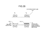
- a carrier in a gaseous state using a CVD reaction tube 120 may also be used.
- CVD chemical vapor deposition
- a boat 122-1 containing an aqueous Na salt solution 121 and a boat 122-2 containing the granulated catalyst 104 are arranged in a CVD reaction tube 120.
- the Na salt is vapor-deposited on the surface of the primary particles of the outermost layer constituting the granulated catalyst 104.
- H 1 and H 2 denote respective heaters for heating the contents of the CVD reaction tube.
- the washing treatment and the reaction inhibiting substance supporting treatment may also be carried out together.
- the fluidized catalyst 12 is an aggregate or an agglomeration of catalyst primary particles formed from a carrier supporting an active component.
- the granulated catalyst which is a secondary particle formed from such catalyst primary particles, has a particle size of 200 ⁇ m to 5 mm, preferably 500 ⁇ m to 2,000 ⁇ m, and more preferably 500 ⁇ m to 1,000 ⁇ m.
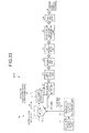
- the nano-carbon material production apparatus 10-78 illustrated in Fig. 32 is further provided with the pH adjustment unit 23 described in the first embodiment on the downstream side of the washing unit 22, in the nano-carbon material production apparatus 10-7A illustrated in Fig. 27 . Consequently, due to the combined effects of the treatment for suppressing the occurrence of a nano-carbon dense layer in the outermost layer of the secondary particles during production of the granulated catalyst and the pH adjustment treatment performed after the acid treatment, nano-carbon material entanglement can be suppressed.
- the nano-carbon material production apparatus 10-7C illustrated in Fig. 33 is further provided with a quick-drying solvent displacement unit 28 on the downstream side of the pH adjustment unit 23, in the nano-carbon material production apparatus 10-7B illustrated in Fig. 32 . Consequently, due to the combined effects of the treatment for suppressing the occurrence of a nano-carbon dense layer in the outermost layer of the secondary particles during production of the granulated catalyst, the pH adjustment treatment performed after the acid treatment, and the prevention of agglomeration among the nano-carbon material by displacing with, for example, acetone, which is a quick-drying solvent, so that the drying rate at the subsequent drying unit 24 improves, nano-carbon material entanglement can be suppressed.
- acetone which is a quick-drying solvent
- Fig. 34 illustrates a schematic diagram of a nano-carbon material production apparatus according to an eighth embodiment for performing a treatment for adding a substance for combustion and removal of nano-carbon.
- Fig. 35 is a schematic diagram of a CNT eliminating substance addition unit by CVD.
- a nano-carbon material production apparatus 10-8A according to the present embodiment includes a nano-carbon material production unit 15, a CNT combustion and removal substance addition unit 73, a combustion treatment unit 74, an acid treatment unit 21, a washing unit 22, and a drying unit 24.
- the nano-carbon material production unit 15 produces a nano-carbon material from a carbon raw material 11 by a fluidized bed reactor 13 using a granulated catalyst formed by granulating a carrier supporting an active component.
- the CNT combustion and removal substance addition unit 73 adds a substance (CNT combustion and removal substance) for combustion and removal of nano-carbon around a granulated having a nano-carbon dense layer formed by aggregation of the nano-carbon formed on the surface of a secondary particle formed from aggregation of catalyst primary particles which are the grown nano-carbon material.
- the combustion treatment unit 74 combusts a nano-carbon dense layer of the surface-treated granulated catalyst.
- the acid treatment unit 21 dissolves and separates a catalyst by an acid solution by feeding the combusted catalyst-containing nano-carbon material into the acid solution.
- the washing unit 22 is provided on the downstream side of the acid treatment unit, and washes the acid-treated nano-carbon material with water.
- the drying unit 24 dries the washed nano-carbon material.
- a substance for combustion and removal of nano-carbon is added to the produced nano-carbon dense layer, so that the nano-carbon dense layer is combusted along with the substance for combustion and removal of nano-carbon, thereby eliminating the produced nano-carbon dense layer.
- Examples of the substance for combustion and removal of nano-carbon include an alkali metal salt such as a Na or K salt (potassium carbonate, sodium carbonate etc.) and an alkaline earth metal salt such as an Mg salt (magnesium carbonate etc.).
- This substance for combustion and removal of nano-carbon may be added by dipping a wire cage, in which the catalyst-containing nano-carbon material 14 has been placed, in a water tank into which an aqueous solution of an alkaline earth metal was charged in advance. Furthermore, a powder of an alkaline earth metal salt may be added.
- This alkaline earth metal salt is present near the surface of the nano-carbon dense layer produced on the surface side of the secondary particles, so that the nano-carbon dense layer is burned off by combustion with oxygen.
- combustion treatment unit 74 It is preferred to perform the combustion in the combustion treatment unit 74 under conditions in the range of 450°C or less, and more preferably 300 to 450°C.
- the carrier formed from an alkali metal salt such as a Na or K salt or an alkaline earth metal salt such as an Mg salt may also be adhered in a powder state.
- a carrier in a gaseous state may also be used.
- CVD chemical vapor deposition
- a boat 122-1 containing an aqueous Mg salt solution 121 and a boat 122-2 containing the catalyst-containing nano-carbon material 14 are arranged in a CVD reaction tube 120.
- the K salt is vapor-deposited on the surface of the primary particles of the outermost layer constituting the granulated catalyst.
- H 1 and H 2 denote respective heaters for heating the contents of the CVD reaction tube.
- a combustion treated product is obtained by adding the substance for combustion and removal of nano-carbon to the catalyst-containing nano-carbon material 14 by the CNT combustion and removal substance addition unit 73 and then eliminating the nano-carbon material dense layer with the combustion treatment unit 74.
- This combustion treated product is fed to the acid treatment unit 21, and subjected to an acid treatment.
- a heat treatment unit is provided on the downstream side of the drying unit 24 and the heat treatment may be carried out at a high temperature (under a nitrogen atmosphere at 300 to 1,200°C, and more preferably 600 to 900°C, for from 30 minutes to 2 hours, and preferably for about 1 hour).
- a high temperature under a nitrogen atmosphere at 300 to 1,200°C, and more preferably 600 to 900°C, for from 30 minutes to 2 hours, and preferably for about 1 hour.
- impurities for example, sulfate radicals etc. produced by a sulfuric acid treatment
- a nano-carbon material having little agglomeration can be produced.
- Fig. 36 illustrates a schematic diagram of another nano-carbon material production apparatus according to the eighth embodiment.
- a nano-carbon material production apparatus 10-8B according to the present embodiment includes a nano-carbon material production unit 15, a steam oxidation treatment unit 75, an acid treatment unit 21, a washing unit 22, and a drying unit 24.
- the nano-carbon material production unit 15 produces a nano-carbon material using a granulated catalyst formed by granulating a carrier supporting an active component.
- the steam oxidation treatment unit 75 performs a steam oxidation treatment on a granulated catalyst having a nano-carbon dense layer formed by aggregation of the nano-carbon formed on the surface of a secondary particle formed from aggregation of catalyst primary particles which are the grown nano-carbon material.
- the acid treatment unit 21 dissolves and separates a catalyst by an acid solution by feeding the steam-oxidation-treated catalyst-containing nano-carbon material into the acid solution.
- the washing unit 22 is provided on the downstream side of the acid treatment unit, and washes the acid-treated nano-carbon material with water.
- the drying unit 24 dries the washed nano-carbon material.
- the nano-carbon dense layer formed by aggregation of the nano-carbon formed on the surface of a secondary particle formed from aggregation of catalyst primary particles which are the grown nano-carbon material can be removed by the steam oxidation treatment with the steam oxidation treatment unit 75.
- the temperature of the steam is preferably 300 to 600°C, and more preferably 400 to 500°C.
- a nano-carbon material having little agglomeration can be produced.
- the nano-carbon material production apparatus 10-8C illustrated in Fig. 37 not only carries out a pre-treatment on the granulated catalyst by the catalyst granulation unit 71 and the granulated catalyst surface treatment unit 72, but is also further provided on the downstream side of the washing unit 22 with the pH adjustment unit 23 and the quick-drying solvent displacement unit 28, in the nano-carbon material production apparatus 10-8A illustrated in Fig. 34 . Consequently, not only is the nano-carbon dense layer eliminated by the addition in advance of the CNT elimination substance during production of the granulated catalyst, but an elimination treatment is also carried out on the catalyst-containing nano-carbon material.
- agglomeration among a nano-carbon material is prevented by performing an anti-agglomeration treatment for preventing agglomeration among the nano-carbon material due to repulsion among oxygen-containing functional groups added to the nano-carbon material before and/or after performing an acid treatment by dispersing a catalyst-containing nano-carbon material in an acid solution.
- the present invention is not limited to the above embodiments. The operation and effects of the present invention can also be enjoyed by further combining the above-described embodiments.
- nano-carbon material production apparatus and method according to the present invention agglomeration can be suppressed, and nano-carbon material yield can be improved.
Landscapes
- Chemical & Material Sciences (AREA)
- Engineering & Computer Science (AREA)
- Nanotechnology (AREA)
- Materials Engineering (AREA)
- Organic Chemistry (AREA)
- Chemical Kinetics & Catalysis (AREA)
- Crystallography & Structural Chemistry (AREA)
- Condensed Matter Physics & Semiconductors (AREA)
- Physics & Mathematics (AREA)
- General Physics & Mathematics (AREA)
- Manufacturing & Machinery (AREA)
- Inorganic Chemistry (AREA)
- Composite Materials (AREA)
- Combustion & Propulsion (AREA)
- Catalysts (AREA)
- Carbon And Carbon Compounds (AREA)
Applications Claiming Priority (8)
| Application Number | Priority Date | Filing Date | Title |
|---|---|---|---|
| JP2008143698 | 2008-05-30 | ||
| JP2008158360 | 2008-06-17 | ||
| JP2008158361 | 2008-06-17 | ||
| JP2008174825 | 2008-07-03 | ||
| JP2008212224 | 2008-08-20 | ||
| JP2008258877 | 2008-10-03 | ||
| JP2008292750 | 2008-11-14 | ||
| PCT/JP2009/059820 WO2009145281A1 (fr) | 2008-05-30 | 2009-05-28 | Appareil et processus pour la production de matériau nanocarbone |
Publications (3)
| Publication Number | Publication Date |
|---|---|
| EP2279982A1 true EP2279982A1 (fr) | 2011-02-02 |
| EP2279982A4 EP2279982A4 (fr) | 2015-12-09 |
| EP2279982B1 EP2279982B1 (fr) | 2020-08-19 |
Family
ID=41377150
Family Applications (1)
| Application Number | Title | Priority Date | Filing Date |
|---|---|---|---|
| EP09754789.7A Active EP2279982B1 (fr) | 2008-05-30 | 2009-05-28 | Appareil pour la production de matériau nanocarbone |
Country Status (6)
| Country | Link |
|---|---|
| US (1) | US8771629B2 (fr) |
| EP (1) | EP2279982B1 (fr) |
| JP (1) | JP5291707B2 (fr) |
| KR (1) | KR101231385B1 (fr) |
| CN (1) | CN102046527A (fr) |
| WO (1) | WO2009145281A1 (fr) |
Families Citing this family (24)
| Publication number | Priority date | Publication date | Assignee | Title |
|---|---|---|---|---|
| JP5839794B2 (ja) * | 2010-11-29 | 2016-01-06 | 東レ株式会社 | カーボンナノチューブ含有組成物の製造方法。 |
| JP5884376B2 (ja) * | 2011-09-30 | 2016-03-15 | 三菱マテリアル株式会社 | カーボンナノファイバー、およびカーボンナノファイバー分散液 |
| KR101472535B1 (ko) | 2013-03-13 | 2014-12-16 | 한국화학연구원 | 2,3-부탄디올로부터 1,3-부타디엔과 메틸에틸케톤을 제조하는 방법 |
| US11383213B2 (en) | 2016-03-15 | 2022-07-12 | Honda Motor Co., Ltd. | System and method of producing a composite product |
| US11171324B2 (en) | 2016-03-15 | 2021-11-09 | Honda Motor Co., Ltd. | System and method of producing a composite product |
| US11081684B2 (en) | 2017-05-24 | 2021-08-03 | Honda Motor Co., Ltd. | Production of carbon nanotube modified battery electrode powders via single step dispersion |
| US20190036102A1 (en) | 2017-07-31 | 2019-01-31 | Honda Motor Co., Ltd. | Continuous production of binder and collector-less self-standing electrodes for li-ion batteries by using carbon nanotubes as an additive |
| US10658651B2 (en) | 2017-07-31 | 2020-05-19 | Honda Motor Co., Ltd. | Self standing electrodes and methods for making thereof |
| US11121358B2 (en) | 2017-09-15 | 2021-09-14 | Honda Motor Co., Ltd. | Method for embedding a battery tab attachment in a self-standing electrode without current collector or binder |
| US11201318B2 (en) | 2017-09-15 | 2021-12-14 | Honda Motor Co., Ltd. | Method for battery tab attachment to a self-standing electrode |
| CN110713021B (zh) * | 2018-07-11 | 2021-03-12 | 河北鸿科碳素有限公司 | 一种煅后焦吸料输送系统装置 |
| US11535517B2 (en) | 2019-01-24 | 2022-12-27 | Honda Motor Co., Ltd. | Method of making self-standing electrodes supported by carbon nanostructured filaments |
| US12381275B2 (en) | 2019-01-30 | 2025-08-05 | Honda Motor Co., Ltd. | Stretchable and flexible lithium ion battery |
| US12142771B2 (en) | 2019-01-30 | 2024-11-12 | Honda Motor Co., Ltd. | Flexible battery as an integration platform for wearable sensors and processing/transmitting devices |
| US11352258B2 (en) | 2019-03-04 | 2022-06-07 | Honda Motor Co., Ltd. | Multifunctional conductive wire and method of making |
| US11325833B2 (en) | 2019-03-04 | 2022-05-10 | Honda Motor Co., Ltd. | Composite yarn and method of making a carbon nanotube composite yarn |
| US11377944B2 (en) | 2019-04-17 | 2022-07-05 | Saudi Arabian Oil Company | Methods of suspending proppants in hydraulic fracturing fluid |
| WO2020214374A1 (fr) | 2019-04-17 | 2020-10-22 | Saudi Arabian Oil Company | Procédés de suspension d'agents alourdissants dans un fluide de forage |
| US11767466B2 (en) | 2019-04-17 | 2023-09-26 | Saudi Arabian Oil Company | Nanocomposite coated proppants and methods of making same |
| US11370951B2 (en) | 2019-04-17 | 2022-06-28 | Saudi Arabian Oil Company | Methods of suspending weighting agents in a drilling fluid |
| US11539042B2 (en) | 2019-07-19 | 2022-12-27 | Honda Motor Co., Ltd. | Flexible packaging with embedded electrode and method of making |
| US11370706B2 (en) | 2019-07-26 | 2022-06-28 | Saudi Arabian Oil Company | Cement slurries, cured cement and methods of making and use thereof |
| US20240051871A1 (en) * | 2022-08-09 | 2024-02-15 | University Of South Carolina | Nano-amended cementitious materials for waste stabilization |
| CN117228746B (zh) * | 2023-11-10 | 2024-02-02 | 泾河新城陕煤技术研究院新能源材料有限公司 | 高球形度富锰前驱体的制备方法 |
Family Cites Families (17)
| Publication number | Priority date | Publication date | Assignee | Title |
|---|---|---|---|---|
| JP2845675B2 (ja) | 1992-06-30 | 1999-01-13 | 日本電気株式会社 | カーボンナノチューブの製造方法 |
| US6183714B1 (en) | 1995-09-08 | 2001-02-06 | Rice University | Method of making ropes of single-wall carbon nanotubes |
| JP3100962B1 (ja) | 1999-07-01 | 2000-10-23 | 株式会社荏原製作所 | カーボンナノファイバーの製造方法及び装置 |
| JP2001139317A (ja) | 1999-11-09 | 2001-05-22 | Natl Inst Of Advanced Industrial Science & Technology Meti | 一方向配列カーボンチューブの製造方法 |
| JP3951896B2 (ja) * | 2001-11-14 | 2007-08-01 | 東レ株式会社 | 炭素質材料の処理方法、カーボンナノチューブ分散液、溶液を得る方法。 |
| JP4349793B2 (ja) | 2002-11-25 | 2009-10-21 | 三菱樹脂株式会社 | 導電性樹脂積層フィルム及びその製造方法 |
| JP4064759B2 (ja) | 2002-08-19 | 2008-03-19 | 三菱重工業株式会社 | カーボンナノファイバーの製造装置及び方法 |
| DE60239138D1 (de) * | 2002-12-12 | 2011-03-24 | Sony Deutschland Gmbh | Lösliche Kohlenstoff-Nanoröhren |
| JP4556409B2 (ja) * | 2003-09-24 | 2010-10-06 | 東レ株式会社 | カーボンナノチューブを含有する組成物の精製方法およびカーボンナノチューブ組成物 |
| JP4501445B2 (ja) * | 2004-02-06 | 2010-07-14 | 東洋インキ製造株式会社 | カーボンナノチューブ組成物、およびそれを含有するカーボンナノチューブ分散液 |
| JP2006225246A (ja) | 2005-02-21 | 2006-08-31 | Mitsubishi Heavy Ind Ltd | ナノカーボン材料 |
| JP4551240B2 (ja) * | 2005-02-24 | 2010-09-22 | 三菱重工業株式会社 | ナノカーボン材料製造用触媒、その製造方法、ナノカーボン材料の製造装置 |
| JP2007297255A (ja) | 2006-05-03 | 2007-11-15 | The Inctec Inc | カーボンナノチューブを含有する分散液 |
| JP2008037696A (ja) | 2006-08-04 | 2008-02-21 | Mitsubishi Heavy Ind Ltd | ナノカーボン材料製造装置及びナノカーボン材料精製方法 |
| JP2008037694A (ja) | 2006-08-04 | 2008-02-21 | Mitsubishi Heavy Ind Ltd | ナノカーボン材料製造装置及びナノカーボン材料精製方法 |
| JP2008037695A (ja) * | 2006-08-04 | 2008-02-21 | Mitsubishi Heavy Ind Ltd | ナノカーボン材料製造装置及びナノカーボン材料精製方法 |
| JP2008056765A (ja) * | 2006-08-30 | 2008-03-13 | Mitsubishi Rayon Co Ltd | カーボンナノチューブ含有構造体及びその製造方法 |
-
2009
- 2009-05-28 KR KR1020107026600A patent/KR101231385B1/ko active Active
- 2009-05-28 WO PCT/JP2009/059820 patent/WO2009145281A1/fr not_active Ceased
- 2009-05-28 EP EP09754789.7A patent/EP2279982B1/fr active Active
- 2009-05-28 US US12/991,197 patent/US8771629B2/en active Active
- 2009-05-28 CN CN2009801200002A patent/CN102046527A/zh active Pending
- 2009-05-28 JP JP2010514542A patent/JP5291707B2/ja active Active
Non-Patent Citations (1)
| Title |
|---|
| See references of WO2009145281A1 * |
Also Published As
| Publication number | Publication date |
|---|---|
| JP5291707B2 (ja) | 2013-09-18 |
| CN102046527A (zh) | 2011-05-04 |
| US8771629B2 (en) | 2014-07-08 |
| US20110060162A1 (en) | 2011-03-10 |
| EP2279982A4 (fr) | 2015-12-09 |
| EP2279982B1 (fr) | 2020-08-19 |
| WO2009145281A1 (fr) | 2009-12-03 |
| KR20100135958A (ko) | 2010-12-27 |
| KR101231385B1 (ko) | 2013-02-07 |
| JPWO2009145281A1 (ja) | 2011-10-13 |
Similar Documents
| Publication | Publication Date | Title |
|---|---|---|
| EP2279982B1 (fr) | Appareil pour la production de matériau nanocarbone | |
| JP5898618B2 (ja) | カーボンナノチューブ凝集体 | |
| JP4160781B2 (ja) | 繊維状ナノ炭素の製造方法及び装置 | |
| CA2344180C (fr) | Croissance catalytique de nanotubes en carbone a paroi unique a partir de particules metalliques | |
| US9126828B2 (en) | Mixed structures of single walled and multi walled carbon nanotubes | |
| KR101785593B1 (ko) | 카본 나노튜브 및 수소의 동시 제조 방법, 및, 카본 나노튜브 및 수소의 동시 제조 장치 | |
| EP1463685B1 (fr) | Procede de production de particules de nanotubes de carbone et d'emetteurs d'electrons les contenant | |
| US20030175200A1 (en) | Catalytic growth of single-wall carbon nanotubes from metal particles | |
| CN101801394A (zh) | 碳纳米管粉末、碳纳米管及其生产方法 | |
| JP7284758B2 (ja) | 窒化ホウ素ナノチューブ材料、及び窒化ホウ素ナノチューブ複合材料 | |
| JP2024506628A (ja) | カーボンナノチューブハイブリッド材料およびハイブリッド材料の製造方法 | |
| JP5422625B2 (ja) | ナノカーボン材料の製造方法 | |
| JP2008037696A (ja) | ナノカーボン材料製造装置及びナノカーボン材料精製方法 | |
| JP2007230816A (ja) | カーボン材料の分散方法及びカーボン材料製造装置 | |
| JP4949794B2 (ja) | ナノカーボン材料製造用触媒の製造方法 | |
| JP2008037694A (ja) | ナノカーボン材料製造装置及びナノカーボン材料精製方法 | |
| JP5818954B2 (ja) | ナノカーボン材料製造装置及びナノカーボン材料精製方法 | |
| JP2008037695A (ja) | ナノカーボン材料製造装置及びナノカーボン材料精製方法 | |
| JP2011178660A (ja) | ナノカーボン材料製造装置及びナノカーボン材料精製方法 | |
| JP2006232595A (ja) | ナノカーボン材料の製造装置及びナノカーボン材料の製造システム | |
| JP2006231107A (ja) | ナノカーボン材料製造用触媒、触媒微粒子、ナノカーボン材料製造用触媒の製造方法 | |
| JP4551240B2 (ja) | ナノカーボン材料製造用触媒、その製造方法、ナノカーボン材料の製造装置 | |
| JP4511972B2 (ja) | ナノカーボン材料生成用担体、その担体の製造方法、ナノカーボン材料製造装置 |
Legal Events
| Date | Code | Title | Description |
|---|---|---|---|
| PUAI | Public reference made under article 153(3) epc to a published international application that has entered the european phase |
Free format text: ORIGINAL CODE: 0009012 |
|
| 17P | Request for examination filed |
Effective date: 20101105 |
|
| AK | Designated contracting states |
Kind code of ref document: A1 Designated state(s): AT BE BG CH CY CZ DE DK EE ES FI FR GB GR HR HU IE IS IT LI LT LU LV MC MK MT NL NO PL PT RO SE SI SK TR |
|
| AX | Request for extension of the european patent |
Extension state: AL BA RS |
|
| DAX | Request for extension of the european patent (deleted) | ||
| RIC1 | Information provided on ipc code assigned before grant |
Ipc: B01J 8/00 20060101ALI20151029BHEP Ipc: B01J 8/18 20060101ALI20151029BHEP Ipc: C01B 31/02 20060101AFI20151029BHEP Ipc: B82Y 40/00 20110101ALI20151029BHEP Ipc: B82Y 30/00 20110101ALI20151029BHEP |
|
| RA4 | Supplementary search report drawn up and despatched (corrected) |
Effective date: 20151109 |
|
| 17Q | First examination report despatched |
Effective date: 20160719 |
|
| STAA | Information on the status of an ep patent application or granted ep patent |
Free format text: STATUS: EXAMINATION IS IN PROGRESS |
|
| REG | Reference to a national code |
Ref country code: DE Ref legal event code: R079 Ref document number: 602009062635 Country of ref document: DE Free format text: PREVIOUS MAIN CLASS: C01B0031020000 Ipc: B01J0008000000 |
|
| RIC1 | Information provided on ipc code assigned before grant |
Ipc: C01B 32/162 20170101ALI20200203BHEP Ipc: B82Y 30/00 20110101ALI20200203BHEP Ipc: B01J 8/18 20060101ALI20200203BHEP Ipc: B01J 8/00 20060101AFI20200203BHEP Ipc: B82Y 40/00 20110101ALI20200203BHEP |
|
| GRAP | Despatch of communication of intention to grant a patent |
Free format text: ORIGINAL CODE: EPIDOSNIGR1 |
|
| STAA | Information on the status of an ep patent application or granted ep patent |
Free format text: STATUS: GRANT OF PATENT IS INTENDED |
|
| INTG | Intention to grant announced |
Effective date: 20200316 |
|
| GRAS | Grant fee paid |
Free format text: ORIGINAL CODE: EPIDOSNIGR3 |
|
| GRAA | (expected) grant |
Free format text: ORIGINAL CODE: 0009210 |
|
| STAA | Information on the status of an ep patent application or granted ep patent |
Free format text: STATUS: THE PATENT HAS BEEN GRANTED |
|
| AK | Designated contracting states |
Kind code of ref document: B1 Designated state(s): AT BE BG CH CY CZ DE DK EE ES FI FR GB GR HR HU IE IS IT LI LT LU LV MC MK MT NL NO PL PT RO SE SI SK TR |
|
| REG | Reference to a national code |
Ref country code: GB Ref legal event code: FG4D |
|
| REG | Reference to a national code |
Ref country code: CH Ref legal event code: NV Representative=s name: BOVARD AG PATENT- UND MARKENANWAELTE, CH Ref country code: CH Ref legal event code: EP |
|
| REG | Reference to a national code |
Ref country code: DE Ref legal event code: R096 Ref document number: 602009062635 Country of ref document: DE |
|
| REG | Reference to a national code |
Ref country code: AT Ref legal event code: REF Ref document number: 1303321 Country of ref document: AT Kind code of ref document: T Effective date: 20200915 |
|
| REG | Reference to a national code |
Ref country code: IE Ref legal event code: FG4D |
|
| REG | Reference to a national code |
Ref country code: LT Ref legal event code: MG4D |
|
| REG | Reference to a national code |
Ref country code: NL Ref legal event code: MP Effective date: 20200819 |
|
| PG25 | Lapsed in a contracting state [announced via postgrant information from national office to epo] |
Ref country code: FI Free format text: LAPSE BECAUSE OF FAILURE TO SUBMIT A TRANSLATION OF THE DESCRIPTION OR TO PAY THE FEE WITHIN THE PRESCRIBED TIME-LIMIT Effective date: 20200819 Ref country code: NO Free format text: LAPSE BECAUSE OF FAILURE TO SUBMIT A TRANSLATION OF THE DESCRIPTION OR TO PAY THE FEE WITHIN THE PRESCRIBED TIME-LIMIT Effective date: 20201119 Ref country code: LT Free format text: LAPSE BECAUSE OF FAILURE TO SUBMIT A TRANSLATION OF THE DESCRIPTION OR TO PAY THE FEE WITHIN THE PRESCRIBED TIME-LIMIT Effective date: 20200819 Ref country code: BG Free format text: LAPSE BECAUSE OF FAILURE TO SUBMIT A TRANSLATION OF THE DESCRIPTION OR TO PAY THE FEE WITHIN THE PRESCRIBED TIME-LIMIT Effective date: 20201119 Ref country code: GR Free format text: LAPSE BECAUSE OF FAILURE TO SUBMIT A TRANSLATION OF THE DESCRIPTION OR TO PAY THE FEE WITHIN THE PRESCRIBED TIME-LIMIT Effective date: 20201120 Ref country code: HR Free format text: LAPSE BECAUSE OF FAILURE TO SUBMIT A TRANSLATION OF THE DESCRIPTION OR TO PAY THE FEE WITHIN THE PRESCRIBED TIME-LIMIT Effective date: 20200819 Ref country code: PT Free format text: LAPSE BECAUSE OF FAILURE TO SUBMIT A TRANSLATION OF THE DESCRIPTION OR TO PAY THE FEE WITHIN THE PRESCRIBED TIME-LIMIT Effective date: 20201221 Ref country code: SE Free format text: LAPSE BECAUSE OF FAILURE TO SUBMIT A TRANSLATION OF THE DESCRIPTION OR TO PAY THE FEE WITHIN THE PRESCRIBED TIME-LIMIT Effective date: 20200819 |
|
| REG | Reference to a national code |
Ref country code: AT Ref legal event code: MK05 Ref document number: 1303321 Country of ref document: AT Kind code of ref document: T Effective date: 20200819 |
|
| PG25 | Lapsed in a contracting state [announced via postgrant information from national office to epo] |
Ref country code: IS Free format text: LAPSE BECAUSE OF FAILURE TO SUBMIT A TRANSLATION OF THE DESCRIPTION OR TO PAY THE FEE WITHIN THE PRESCRIBED TIME-LIMIT Effective date: 20201219 Ref country code: PL Free format text: LAPSE BECAUSE OF FAILURE TO SUBMIT A TRANSLATION OF THE DESCRIPTION OR TO PAY THE FEE WITHIN THE PRESCRIBED TIME-LIMIT Effective date: 20200819 Ref country code: LV Free format text: LAPSE BECAUSE OF FAILURE TO SUBMIT A TRANSLATION OF THE DESCRIPTION OR TO PAY THE FEE WITHIN THE PRESCRIBED TIME-LIMIT Effective date: 20200819 Ref country code: NL Free format text: LAPSE BECAUSE OF FAILURE TO SUBMIT A TRANSLATION OF THE DESCRIPTION OR TO PAY THE FEE WITHIN THE PRESCRIBED TIME-LIMIT Effective date: 20200819 |
|
| PG25 | Lapsed in a contracting state [announced via postgrant information from national office to epo] |
Ref country code: RO Free format text: LAPSE BECAUSE OF FAILURE TO SUBMIT A TRANSLATION OF THE DESCRIPTION OR TO PAY THE FEE WITHIN THE PRESCRIBED TIME-LIMIT Effective date: 20200819 Ref country code: CZ Free format text: LAPSE BECAUSE OF FAILURE TO SUBMIT A TRANSLATION OF THE DESCRIPTION OR TO PAY THE FEE WITHIN THE PRESCRIBED TIME-LIMIT Effective date: 20200819 Ref country code: DK Free format text: LAPSE BECAUSE OF FAILURE TO SUBMIT A TRANSLATION OF THE DESCRIPTION OR TO PAY THE FEE WITHIN THE PRESCRIBED TIME-LIMIT Effective date: 20200819 Ref country code: EE Free format text: LAPSE BECAUSE OF FAILURE TO SUBMIT A TRANSLATION OF THE DESCRIPTION OR TO PAY THE FEE WITHIN THE PRESCRIBED TIME-LIMIT Effective date: 20200819 |
|
| REG | Reference to a national code |
Ref country code: DE Ref legal event code: R097 Ref document number: 602009062635 Country of ref document: DE |
|
| PG25 | Lapsed in a contracting state [announced via postgrant information from national office to epo] |
Ref country code: ES Free format text: LAPSE BECAUSE OF FAILURE TO SUBMIT A TRANSLATION OF THE DESCRIPTION OR TO PAY THE FEE WITHIN THE PRESCRIBED TIME-LIMIT Effective date: 20200819 Ref country code: AT Free format text: LAPSE BECAUSE OF FAILURE TO SUBMIT A TRANSLATION OF THE DESCRIPTION OR TO PAY THE FEE WITHIN THE PRESCRIBED TIME-LIMIT Effective date: 20200819 |
|
| PLBE | No opposition filed within time limit |
Free format text: ORIGINAL CODE: 0009261 |
|
| STAA | Information on the status of an ep patent application or granted ep patent |
Free format text: STATUS: NO OPPOSITION FILED WITHIN TIME LIMIT |
|
| PG25 | Lapsed in a contracting state [announced via postgrant information from national office to epo] |
Ref country code: SK Free format text: LAPSE BECAUSE OF FAILURE TO SUBMIT A TRANSLATION OF THE DESCRIPTION OR TO PAY THE FEE WITHIN THE PRESCRIBED TIME-LIMIT Effective date: 20200819 |
|
| 26N | No opposition filed |
Effective date: 20210520 |
|
| PG25 | Lapsed in a contracting state [announced via postgrant information from national office to epo] |
Ref country code: SI Free format text: LAPSE BECAUSE OF FAILURE TO SUBMIT A TRANSLATION OF THE DESCRIPTION OR TO PAY THE FEE WITHIN THE PRESCRIBED TIME-LIMIT Effective date: 20200819 |
|
| PG25 | Lapsed in a contracting state [announced via postgrant information from national office to epo] |
Ref country code: LU Free format text: LAPSE BECAUSE OF NON-PAYMENT OF DUE FEES Effective date: 20210528 Ref country code: MC Free format text: LAPSE BECAUSE OF FAILURE TO SUBMIT A TRANSLATION OF THE DESCRIPTION OR TO PAY THE FEE WITHIN THE PRESCRIBED TIME-LIMIT Effective date: 20200819 |
|
| REG | Reference to a national code |
Ref country code: BE Ref legal event code: MM Effective date: 20210531 |
|
| PG25 | Lapsed in a contracting state [announced via postgrant information from national office to epo] |
Ref country code: IE Free format text: LAPSE BECAUSE OF NON-PAYMENT OF DUE FEES Effective date: 20210528 |
|
| PG25 | Lapsed in a contracting state [announced via postgrant information from national office to epo] |
Ref country code: BE Free format text: LAPSE BECAUSE OF NON-PAYMENT OF DUE FEES Effective date: 20210531 |
|
| REG | Reference to a national code |
Ref country code: DE Ref legal event code: R082 Ref document number: 602009062635 Country of ref document: DE Representative=s name: CBDL PATENTANWAELTE GBR, DE Ref country code: DE Ref legal event code: R082 Ref document number: 602009062635 Country of ref document: DE Representative=s name: CBDL PATENTANWAELTE EGBR, DE |
|
| REG | Reference to a national code |
Ref country code: FR Ref legal event code: PLFP Year of fee payment: 15 |
|
| PG25 | Lapsed in a contracting state [announced via postgrant information from national office to epo] |
Ref country code: HU Free format text: LAPSE BECAUSE OF FAILURE TO SUBMIT A TRANSLATION OF THE DESCRIPTION OR TO PAY THE FEE WITHIN THE PRESCRIBED TIME-LIMIT; INVALID AB INITIO Effective date: 20090528 Ref country code: CY Free format text: LAPSE BECAUSE OF FAILURE TO SUBMIT A TRANSLATION OF THE DESCRIPTION OR TO PAY THE FEE WITHIN THE PRESCRIBED TIME-LIMIT Effective date: 20200819 |
|
| PG25 | Lapsed in a contracting state [announced via postgrant information from national office to epo] |
Ref country code: MK Free format text: LAPSE BECAUSE OF FAILURE TO SUBMIT A TRANSLATION OF THE DESCRIPTION OR TO PAY THE FEE WITHIN THE PRESCRIBED TIME-LIMIT Effective date: 20200819 |
|
| PG25 | Lapsed in a contracting state [announced via postgrant information from national office to epo] |
Ref country code: TR Free format text: LAPSE BECAUSE OF FAILURE TO SUBMIT A TRANSLATION OF THE DESCRIPTION OR TO PAY THE FEE WITHIN THE PRESCRIBED TIME-LIMIT Effective date: 20200819 |
|
| PGFP | Annual fee paid to national office [announced via postgrant information from national office to epo] |
Ref country code: CH Payment date: 20240602 Year of fee payment: 16 |
|
| PG25 | Lapsed in a contracting state [announced via postgrant information from national office to epo] |
Ref country code: MT Free format text: LAPSE BECAUSE OF FAILURE TO SUBMIT A TRANSLATION OF THE DESCRIPTION OR TO PAY THE FEE WITHIN THE PRESCRIBED TIME-LIMIT Effective date: 20200819 |
|
| PGFP | Annual fee paid to national office [announced via postgrant information from national office to epo] |
Ref country code: DE Payment date: 20250402 Year of fee payment: 17 |
|
| PGFP | Annual fee paid to national office [announced via postgrant information from national office to epo] |
Ref country code: IT Payment date: 20250422 Year of fee payment: 17 |
|
| PGFP | Annual fee paid to national office [announced via postgrant information from national office to epo] |
Ref country code: FR Payment date: 20250401 Year of fee payment: 17 |
|
| REG | Reference to a national code |
Ref country code: CH Ref legal event code: H13 Free format text: ST27 STATUS EVENT CODE: U-0-0-H10-H13 (AS PROVIDED BY THE NATIONAL OFFICE) Effective date: 20251223 |
|
| PG25 | Lapsed in a contracting state [announced via postgrant information from national office to epo] |
Ref country code: CH Free format text: LAPSE BECAUSE OF NON-PAYMENT OF DUE FEES Effective date: 20250531 |
|
| PGFP | Annual fee paid to national office [announced via postgrant information from national office to epo] |
Ref country code: GB Payment date: 20260323 Year of fee payment: 18 |