EP2279983A2 - Vorrichtung und Verfahren zur Verarbeitung eines Brüchigmaterialsubstrats - Google Patents
Vorrichtung und Verfahren zur Verarbeitung eines Brüchigmaterialsubstrats Download PDFInfo
- Publication number
- EP2279983A2 EP2279983A2 EP10165986A EP10165986A EP2279983A2 EP 2279983 A2 EP2279983 A2 EP 2279983A2 EP 10165986 A EP10165986 A EP 10165986A EP 10165986 A EP10165986 A EP 10165986A EP 2279983 A2 EP2279983 A2 EP 2279983A2
- Authority
- EP
- European Patent Office
- Prior art keywords
- brittle material
- scribing
- resin layer
- trench
- blade
- Prior art date
- Legal status (The legal status is an assumption and is not a legal conclusion. Google has not performed a legal analysis and makes no representation as to the accuracy of the status listed.)
- Withdrawn
Links
- 239000000758 substrate Substances 0.000 title claims abstract description 64
- 239000000463 material Substances 0.000 title claims abstract description 54
- 238000000034 method Methods 0.000 title claims abstract description 31
- 239000011347 resin Substances 0.000 claims abstract description 71
- 229920005989 resin Polymers 0.000 claims abstract description 71
- 239000000428 dust Substances 0.000 claims description 10
- 239000002245 particle Substances 0.000 claims description 10
- 238000003825 pressing Methods 0.000 claims description 10
- 230000003287 optical effect Effects 0.000 claims description 8
- 238000005096 rolling process Methods 0.000 claims description 4
- 239000011521 glass Substances 0.000 description 66
- 238000010586 diagram Methods 0.000 description 18
- 238000003672 processing method Methods 0.000 description 4
- 239000000919 ceramic Substances 0.000 description 2
- 238000007796 conventional method Methods 0.000 description 2
- 229910003460 diamond Inorganic materials 0.000 description 2
- 239000010432 diamond Substances 0.000 description 2
- 230000000694 effects Effects 0.000 description 2
- 239000004065 semiconductor Substances 0.000 description 2
- 238000005299 abrasion Methods 0.000 description 1
- 238000005520 cutting process Methods 0.000 description 1
- 230000001681 protective effect Effects 0.000 description 1
- 238000003892 spreading Methods 0.000 description 1
Images


Classifications
-
- C—CHEMISTRY; METALLURGY
- C03—GLASS; MINERAL OR SLAG WOOL
- C03B—MANUFACTURE, SHAPING, OR SUPPLEMENTARY PROCESSES
- C03B33/00—Severing cooled glass
- C03B33/07—Cutting armoured, multi-layered, coated or laminated, glass products
- C03B33/074—Glass products comprising an outer layer or surface coating of non-glass material
-
- B—PERFORMING OPERATIONS; TRANSPORTING
- B28—WORKING CEMENT, CLAY, OR STONE
- B28D—WORKING STONE OR STONE-LIKE MATERIALS
- B28D1/00—Working stone or stone-like materials, e.g. brick, concrete or glass, not provided for elsewhere; Machines, devices, tools therefor
- B28D1/22—Working stone or stone-like materials, e.g. brick, concrete or glass, not provided for elsewhere; Machines, devices, tools therefor by cutting, e.g. incising
- B28D1/225—Working stone or stone-like materials, e.g. brick, concrete or glass, not provided for elsewhere; Machines, devices, tools therefor by cutting, e.g. incising for scoring or breaking, e.g. tiles
- B28D1/226—Working stone or stone-like materials, e.g. brick, concrete or glass, not provided for elsewhere; Machines, devices, tools therefor by cutting, e.g. incising for scoring or breaking, e.g. tiles with plural scoring tools
-
- B—PERFORMING OPERATIONS; TRANSPORTING
- B28—WORKING CEMENT, CLAY, OR STONE
- B28D—WORKING STONE OR STONE-LIKE MATERIALS
- B28D5/00—Fine working of gems, jewels, crystals, e.g. of semiconductor material; apparatus or devices therefor
- B28D5/0005—Fine working of gems, jewels, crystals, e.g. of semiconductor material; apparatus or devices therefor by breaking, e.g. dicing
- B28D5/0011—Fine working of gems, jewels, crystals, e.g. of semiconductor material; apparatus or devices therefor by breaking, e.g. dicing with preliminary treatment, e.g. weakening by scoring
-
- C—CHEMISTRY; METALLURGY
- C03—GLASS; MINERAL OR SLAG WOOL
- C03B—MANUFACTURE, SHAPING, OR SUPPLEMENTARY PROCESSES
- C03B33/00—Severing cooled glass
- C03B33/10—Glass-cutting tools, e.g. scoring tools
- C03B33/105—Details of cutting or scoring means, e.g. tips
- C03B33/107—Wheel design, e.g. materials, construction, shape
Definitions
- the present invention relates to a method and an apparatus for processing a brittle material substrate, such as touch panels and glass with a protective film which are glass substrates, having a resin layer, for example, a film, on the surface of a brittle material (glass, ceramics and semiconductor materials).
- a brittle material substrate such as touch panels and glass with a protective film which are glass substrates, having a resin layer, for example, a film, on the surface of a brittle material (glass, ceramics and semiconductor materials).
- a method for dividing a glass substrate As one conventional method for dividing a glass substrate, a method is used for dividing a glass substrate according to which a glass substrate is fixed on a table using a vacuum suction mechanism, a scribing trench is created on one side of the glass substrate by means of a cutter wheel for glass with a large angle between the ridge lines at the edge of a blade, and after that, pressure is applied along the scribing trench using a pressure means, such as a break bar or a roller, so that a vertical crack extends.
- a pressure means such as a break bar or a roller
- a cut trench 31 is created in the resin layer 21 by running a sharp fixed blade 30 with a small angle between the ridge lines at the edge along a line, which is where the substrate is to be scribed, as it is pressed against the substrate.
- the cutting is adjusted such that this cut trench 31 is created only in the resin layer and not in the glass plate.
- the resin layer is cut with a sharp fixed blade 30 with a small angle between the ridge lines because the resin layer cannot be cut with a blade with a large angle between the ridge lines.
- the glass substrate W is turned over and a scribing trench 33 is created in the glass plate 20 along the previously created cut trench 31 on the opposite side by rolling a cutter wheel 32 for glass with a large angle between the ridge lines at the edge over it.
- the glass substrate is scribed with a cutter wheel 32 with a large angle between the ridge lines at the edge because a scribing trench cannot be created with an edge having a small angle between the ridge lines and the glass substrate suddenly breaks when an excessive load is applied, even if it is by a small margin.
- the resin layer is cut with a fixed blade on one side, the substrate is turned over, and the glass is scribed on the other side with a cutter wheel, and thus, a dividing process is carried out.
- an object of the present invention is to provide a method and an apparatus for processing a glass substrate where a resin layer is formed on one side, according to which a cut trench and a scribing trench can both be effectively created in the resin layer and the glass plate from the same side without turning over the glass substrate when a dividing process is carried out on the glass substrate.
- the processing method according to the present invention is a method for processing a glass substrate where a resin layer is formed on one side, and first, a cut trench is created in the resin layer with a resin dividing means from the top on the resin layer side.
- the resin dividing means is not particularly limited as long as it can divide a resin layer, and it is preferable to use a fixed blade for mechanically dividing a resin layer or a laser for thermally dividing a resin layer.
- a cutter wheel having a structure as described below is used so that a scribing trench is created in the glass plate by rolling this cutter wheel along the above described cut trench over the top of the resin layer side as it is pressed against the glass plate.
- the cutter wheel for scribing a glass plate has a blade for scribing glass with an angle ⁇ between the ridge lines in the edge portion of the blade and second inclining surfaces that continue from the first inclining surfaces on the left and right of the blade for scribing glass so that the angle ⁇ , at which the imaginary lines along the second inclining surfaces on the left and right cross, is smaller than the above described angle ⁇ between the ridge lines in the edge portion, and thus, the cutter wheel has inclining surfaces with two angles.
- the angle ⁇ between the ridge lines at the edge of the above described cutter wheel may be between 80 degrees and 160 degrees (usually between 90 degrees and 145 degrees, particularly between 90 degrees and 130 degrees), and the angle ⁇ at which the imaginary lines along the second inclining surfaces cross may be between 10 degrees and 70 degrees (usually between 15 degrees and 55 degrees, particularly between 25 degrees and 40 degrees).
- a cut trench is created in the resin layer with a resin dividing means, such as a laser beam or a fixed blade, and subsequently, the substrate is scribed on the side on which the resin layer is formed with a cutter wheel having inclining surfaces with two angles.
- the cutter wheel having inclining surfaces with two angles is used because of the following reasons.
- cutter wheels for scribing a brittle material, such as glass have such a structure that a scribing trench is created by rolling it as it is pressed against glass, and therefore, the angle ⁇ between the ridge lines at the edge is large.
- a cutter wheel is provided with inclining surfaces with two angles so that the portion of the cutter wheel that enters into the resin layer is thin, thus preventing the second inclining surfaces from making contact with the resin layer when the brittle material substrate is scribed with the edge surfaces (first inclining surfaces) having a large angle ⁇ between the ridge lines at the edge, and as a result, the edge portions of the cut trench in the resin layer can be prevented from being broken or torn away.
- the brittle material substrate can be scribed along the cut trench over the top on the resin layer side with a cutter wheel having the above described inclining surfaces with two angles, and thus, a scribing trench can be created in the brittle material substrate from the same side without turning over the brittle material substrate.
- the present invention is particularly effective in the case where the width of the cut trench created in the resin layer is in such a range as to be 200 ⁇ m or less, and particularly 100 ⁇ m or less (usually 20 ⁇ m or greater), for example.
- the fixed blade or the laser beam illuminating optical system for creating a cut trench as described above and the cutter wheel for creating a scribing trench in a brittle material plate may be aligned along the same straight line so that the creation of a cut trench in the resin layer and the creation of a scribing trench in the brittle material plate can be continuously carried out as one operation. As a result, the processing time can further be reduced.
- the suction apparatus for sucking dust and particles and a pressing roller for flattening the surface may be aligned along the same straight line subsequent to the cutter wheel so that the creation of a cut trench in the resin layer, the creation of a scribing trench in the brittle material plate, the suction of dust and particles and the flattening of the surface can be carried out in sequence as one operation.
- the suction apparatus for sucking dust and particles and a pressing roller for flattening the surface may be aligned along the same straight line subsequent to the cutter wheel so that the creation of a cut trench in the resin layer, the creation of a scribing trench in the brittle material plate, the suction of dust and particles and the flattening of the surface can be carried out in sequence as one operation.
- the dust and particles are sucked and removed, and at the same time, the burrs disappear when the surface is pressed and flattened so that the processed product can be high quality.
- these tasks can be achieved through one operation, and therefore, an increase in the processing efficiency
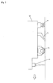
- Fig 1 is a perspective diagram showing an embodiment of a processing apparatus A that is used for the processing method according to the present invention.
- the processing apparatus A is provided with a table 10 that can be moved in approximately the horizontal direction (Y direction) and can rotate in a horizontal plane.
- the table 10 is provided with a vacuum suction mechanism for holding a glass substrate W (not shown).
- a bridge 13 that is formed of supports 11, 11 on the two sides of the table 10 and a guide bar 12 extending in the X direction is provided over the table 10 and can move in the Y direction by means of a movement mechanism, not shown.
- a slider 14 is attached so as to be movable along the guide 15 formed on the guide bar 12 and moves in the X direction as the motor 16 rotates.
- An attachment base 5 for holding the below described fixed blade 1 or cutter wheel 2 is attached to the slider 14 via a stay 7 that can move upwards and downwards.
- a fixed blade 1, a cutter wheel 2, a suction apparatus 3 for removing dust and particles and a pressing roller 4 are attached to the attachment base 5 in such a state that they are aligned along a straight line with the fixed blade 1 at the forefront.
- Fig 4 is a cross sectional diagram showing the fixed blade 1.
- the fixed blade 1 is made of a hard material, such as sintered diamond or carbide, and formed so as to have a sharp edge with a small angle ⁇ between the ridge lines at the edge. It is preferable for this angle ⁇ between the ridge lines at the edge to be in a range between 25 degrees and 40 degrees, and it is particularly preferable for it to be 30 degrees.
- the position of the fixed blade 1 can be microscopically adjusted upwards and downwards by means of an upward and downward adjusting mechanism 1d.
- Fig 5 is a cross sectional diagram showing the cutter wheel
- Fig 6 is a diagram showing an enlargement of a portion thereof.
- the cutter wheel 2 is made of a hard material, such as sintered diamond or carbide, like the fixed blade 1.
- a blade 2a for scribing glass with a large angle ⁇ between the ridge lines is formed in the edge portion of this cutter wheel 2, and there are second inclining surfaces 2c which continue from the first inclining surface 2b on the left and right of the blade 2a for scribing glass.
- the angle ⁇ at which the imaginary straight line along the second inclining surfaces 2c, 2c on the left and right cross is smaller than the angle ⁇ between the ridge lines at the edge as described above, and as a result, the two sides, left and right, of the blade are provided with inclining surfaces with two angles.
- angle ⁇ between the ridge lines at the edge 2a is preferable for the above described angle ⁇ between the ridge lines at the edge 2a to be between 80 degrees and 160 degrees, it is more preferable for it to be between 90 degrees and 145 degrees, and it is most preferable for it to be between 90 degrees and 130 degrees, while it is preferable for the angle ⁇ at which the imaginary straight lines along the second inclining surfaces cross to be between 10 degrees and 70 degrees, it is more preferable for it to be between 15 degrees and 55 degrees, it is even more preferable for it to be between 25 degrees and 40 degrees, and it is most preferable for it to be approximately 30 degrees.
- the position of the cutter wheel 2 can be microscopically adjusted upwards and downwards by means of an upward and downward adjusting mechanism 2d (see Fig 2 ) like the fixed blade 1.
- Figs 8 to 11 are diagrams showing the procedure when a glass substrate on which a resin layer is formed is divided.
- the glass substrate W that is to be scribed according to the present invention is a substrate for a touch panel or the like where a thin resin layer 21 is formed on one side of a glass plate 20.
- This glass substrate W is placed and fixed on a table 10 so that the resin layer 21 faces upwards as shown in Fig 8 .
- the attachment base 5 is lowered so that the fixed blade 1 and the cutter wheel 2 become of such a state as to be positioned for scribing, and the attachment base 5 is moved with the fixed blade 1 at the front while being pressed against the glass substrate W.
- the sharp fixed blade 1 creates a cut trench 22 in the resin layer 21 as shown in Fig 8 .
- the positioning of the system is set so that the edge of the fixed blade 1 does not hit the glass plate 20.
- only the resin layer 21 is processed with the sharp fixed blade 1, and a precisely cut trench 22 is created.
- the following cutter wheel 2 rolls over the glass plate 20 along the cut trench 22 while being pressed, and thus, a scribing trench 23 is created in the glass plate 20.
- the angle ⁇ between the ridge lines at the edge of the cutter wheel 2 is large enough for scribing glass, and therefore, the scribing trench 23 can be effectively created on the glass plate 20.
- the angle ⁇ between the second inclining surfaces 2c which exclude this edge 2a portion is small so that the edge portion of the cutter wheel 2 that engages with this cut trench 22 is thin.
- the following suction apparatus 3 sucks and removes dust and microscopic particles resulting from the scribing of the glass plate 20, and then, the following pressing roller 4 flattens and precisely presses down the burrs 22a which slightly rise from the edge portions of the cut trench 22 (see Figs 10 and 11 ).
- the following pressing roller 4 flattens and precisely presses down the burrs 22a which slightly rise from the edge portions of the cut trench 22 (see Figs 10 and 11 ).
- a laser beam illuminating optical system 6 may be attached to the attachment base 5 as shown in Fig 7 instead of the fixed blade 1 so that the cut trench 22 is created by means of a laser beam (laser abrasion process).
- the present invention is not necessarily limited to the above described embodiments.
- the attachment base 5 is moved relative to the glass substrate W in the above described embodiments, the glass substrate W may be moved with the attachment base 5 being fixed.
- the present invention is appropriate for a brittle material substrate on which a resin layer is formed (for example, a ceramic substrate or a semiconductor material substrate) other than glass substrates on which a resin layer is formed.
- the dividing method according to the present invention can be used to carry out a dividing process on a brittle material substrate where a resin layer is formed on the surface of a brittle material, for example, a glass substrate such as a touch panel, where a thin resin layer is formed on one side of a glass plate.
- a cut trench 22 is created in a resin layer 21 from the top by means of a fixed blade 1 or a laser beam, and then the brittle material plate is scribed along the above described cut trench 22 with a cutter wheel 2 having inclining surfaces with two angles on the two sides of the blade, and thus, a scribing trench 23 is created in the brittle material plate.
- the above described cutter wheel 2 is provided with a blade 2a for scribing a brittle material having a large angle ⁇ between the ridge lines in the edge portion and second inclining surfaces 2c which continue from the first inclining surfaces 2b on the left and right of the blade 2a for scribing a brittle material so that the angle ⁇ at which the virtual lines along the left and right second inclining surfaces cross is smaller than the angle ⁇ between the ridge lines in the above described edge portion, and thus, the two sides of the blade have inclining surfaces with two angles in the structure.
Landscapes
- Engineering & Computer Science (AREA)
- Chemical & Material Sciences (AREA)
- Mechanical Engineering (AREA)
- Materials Engineering (AREA)
- Organic Chemistry (AREA)
- Mining & Mineral Resources (AREA)
- Processing Of Stones Or Stones Resemblance Materials (AREA)
- Re-Forming, After-Treatment, Cutting And Transporting Of Glass Products (AREA)
- Laser Beam Processing (AREA)
Applications Claiming Priority (1)
| Application Number | Priority Date | Filing Date | Title |
|---|---|---|---|
| JP2009179852A JP5438422B2 (ja) | 2009-07-31 | 2009-07-31 | 脆性材料基板の加工方法並びに加工装置 |
Publications (2)
| Publication Number | Publication Date |
|---|---|
| EP2279983A2 true EP2279983A2 (de) | 2011-02-02 |
| EP2279983A3 EP2279983A3 (de) | 2013-09-11 |
Family
ID=42938248
Family Applications (1)
| Application Number | Title | Priority Date | Filing Date |
|---|---|---|---|
| EP10165986.0A Withdrawn EP2279983A3 (de) | 2009-07-31 | 2010-06-15 | Vorrichtung und Verfahren zur Verarbeitung eines Brüchigmaterialsubstrats |
Country Status (5)
| Country | Link |
|---|---|
| EP (1) | EP2279983A3 (de) |
| JP (1) | JP5438422B2 (de) |
| KR (1) | KR101200788B1 (de) |
| CN (1) | CN101987775B (de) |
| TW (1) | TWI432387B (de) |
Cited By (9)
| Publication number | Priority date | Publication date | Assignee | Title |
|---|---|---|---|---|
| EP2481543A1 (de) * | 2011-01-27 | 2012-08-01 | Mitsuboshi Diamond Industrial Co., Ltd. | Verfahren zum Anreißen eines Substrats aus brüchigem Material |
| EP2937196A4 (de) * | 2012-12-18 | 2015-12-09 | Bellota Herramientas Sa | Klinge für ein schneidewerkzeug einer keramischen schneidemaschine |
| EP3034478A1 (de) * | 2014-12-18 | 2016-06-22 | Macotec S.R.L. | Vorrichtung zur behandlung der oberfläche von scheibenelementen, wie etwa glasscheiben |
| US9446566B2 (en) | 2011-05-13 | 2016-09-20 | Nippon Electric Glass Co., Ltd. | Laminate, method for cutting laminate, method for processing laminate, and device and method for cutting brittle plate-like object |
| WO2019185279A1 (de) * | 2018-03-29 | 2019-10-03 | Hegla Boraident Gmbh & Co. Kg | Entschichtungseinrichtungen und -verfahren zum entschichten von glastafeln, vorzugsweise verbundglastafeln |
| DE102018010277B4 (de) | 2018-03-29 | 2022-01-13 | Hegla Boraident Gmbh & Co. Kg | Entschichtungsverfahren und Verwendung einer Entschichtungseinrichtung zum Entschichten von Glastafeln, vorzugsweise Verbundglastafeln |
| CN115781941A (zh) * | 2022-11-25 | 2023-03-14 | 合肥陶陶新材料科技有限公司 | 一种陶瓷表面雕花设备 |
| CN116749360A (zh) * | 2023-08-04 | 2023-09-15 | 泰山石膏(包头)有限公司 | 石膏板切割装置 |
| CN118456680A (zh) * | 2024-07-10 | 2024-08-09 | 响水县凯瑞钢化玻璃制品有限公司 | 一种钢化玻璃定位滑切装置 |
Families Citing this family (24)
| Publication number | Priority date | Publication date | Assignee | Title |
|---|---|---|---|---|
| JP2011218607A (ja) * | 2010-04-06 | 2011-11-04 | Sharp Corp | 基板分割装置および基板分割方法 |
| JP5271394B2 (ja) * | 2011-07-20 | 2013-08-21 | 三星ダイヤモンド工業株式会社 | レーザスクライブ装置 |
| KR101144264B1 (ko) | 2011-10-07 | 2012-05-11 | 전선화 | 디스플레이용 강화유리창 제조방법 및 이에 의해 제조된 강화유리창 |
| TWI458108B (zh) * | 2011-12-07 | 2014-10-21 | Ind Tech Res Inst | 渠道刻劃裝置以及渠道刻劃方法 |
| JP6043150B2 (ja) * | 2012-10-29 | 2016-12-14 | 三星ダイヤモンド工業株式会社 | 積層脆性材料基板のブレイク装置および積層脆性材料基板のブレイク方法 |
| CN103085106B (zh) * | 2013-02-01 | 2015-09-30 | 四川虹视显示技术有限公司 | Oled基板切割系统 |
| JP6357746B2 (ja) * | 2013-09-24 | 2018-07-18 | 三星ダイヤモンド工業株式会社 | スクライビングホイール、ホルダユニット、スクライブ装置、スクライビングホイールの製造方法及びスクライブ方法 |
| JP6268917B2 (ja) * | 2013-10-25 | 2018-01-31 | 三星ダイヤモンド工業株式会社 | ブレイク装置 |
| CN103739191A (zh) * | 2013-11-13 | 2014-04-23 | 上海和辉光电有限公司 | 切割吸尘装置及切割方法 |
| CN104766904B (zh) * | 2014-01-06 | 2017-01-11 | 大族激光科技产业集团股份有限公司 | Cigs薄膜太阳能电池刻划设备 |
| JP6332618B2 (ja) * | 2014-04-24 | 2018-05-30 | 三星ダイヤモンド工業株式会社 | スクライブ用カッターホイール並びにスクライブ装置 |
| JP6287547B2 (ja) * | 2014-04-28 | 2018-03-07 | 三星ダイヤモンド工業株式会社 | 脆性材料基板の反転装置 |
| JP6299405B2 (ja) * | 2014-05-13 | 2018-03-28 | 旭硝子株式会社 | 複合体の製造方法および積層体の製造方法 |
| KR102446856B1 (ko) * | 2016-06-29 | 2022-09-23 | 삼성디스플레이 주식회사 | 커버 윈도우 및 그 제조 방법 |
| CN107363877B (zh) * | 2017-07-25 | 2019-02-12 | 武汉华星光电半导体显示技术有限公司 | 一种切割装置及切割方法 |
| JP6949371B2 (ja) * | 2017-12-15 | 2021-10-13 | 三星ダイヤモンド工業株式会社 | 基板分断装置 |
| CN108059335B (zh) * | 2018-01-04 | 2021-01-26 | 京东方科技集团股份有限公司 | 切割方法 |
| CN108588636B (zh) * | 2018-04-26 | 2019-10-01 | 山东大学 | 一种提高脆性材料机械加工表面完整性的方法 |
| CN109333831B (zh) * | 2018-12-13 | 2024-06-07 | 佛山市爱陶机电设备有限公司 | 一种瓷砖切割工艺及瓷砖切割设备 |
| CN109808080A (zh) * | 2019-03-26 | 2019-05-28 | 云浮市科特机械有限公司 | 一种双刀切割工艺 |
| CN111844478B (zh) * | 2020-06-29 | 2022-03-18 | 深圳市鸿昇自动化设备有限公司 | 一种手机屏幕切割加工设备及手机屏幕切割加工方法 |
| CN112757506B (zh) * | 2020-12-31 | 2022-07-05 | 青岛建设集团股份有限公司 | 带有扶正限位的坡面与墙体交接处开槽器 |
| CN113696248B (zh) * | 2021-10-29 | 2022-01-07 | 四川英创力电子科技股份有限公司 | 一种高精密在ptfe高频电路板上成型深槽的设备及方法 |
| CN116135503B (zh) * | 2021-11-18 | 2025-07-25 | 广东博智林机器人有限公司 | 板料分割设备 |
Family Cites Families (18)
| Publication number | Priority date | Publication date | Assignee | Title |
|---|---|---|---|---|
| JPS62158129A (ja) * | 1985-12-27 | 1987-07-14 | Kyocera Corp | ガラス切断用ホイ−ルカツタ |
| JPH01256956A (ja) * | 1988-04-08 | 1989-10-13 | Shinkiyokutou Sangyo Kk | 生理吸収具の表面材の製造方法 |
| JPH11105141A (ja) * | 1997-08-04 | 1999-04-20 | Kyodo Giken Kagaku Kk | 多孔性フィルム及びその製造方法 |
| JP3759317B2 (ja) * | 1998-08-04 | 2006-03-22 | トーヨー産業株式会社 | ガラス切断専用のカッターホイール |
| JP2001058317A (ja) * | 1999-08-20 | 2001-03-06 | Berudekkusu:Kk | スクライブ方法および装置 |
| JP4433555B2 (ja) * | 2000-03-23 | 2010-03-17 | 坂東機工株式会社 | ガラス板の加工方法及びその装置 |
| JP2001347416A (ja) * | 2000-06-06 | 2001-12-18 | Matsushita Electric Ind Co Ltd | 切断装置及び切断方法 |
| JP2002060234A (ja) * | 2000-08-16 | 2002-02-26 | Nippon Electric Glass Co Ltd | 透明板状物の切断方法及び装置 |
| CN100410196C (zh) * | 2001-11-08 | 2008-08-13 | 夏普株式会社 | 切割玻璃基体的方法和装置、液晶板以及制造液晶板的装置 |
| KR100633488B1 (ko) * | 2001-11-08 | 2006-10-13 | 샤프 가부시키가이샤 | 유리 기판의 분단 방법, 유리 기판의 분단 장치 및 액정 패널 제조 장치 |
| KR100568091B1 (ko) * | 2003-03-17 | 2006-04-07 | 신한다이아몬드공업 주식회사 | 원추형 피시디 스크라이버 커터와 그의 커팅홈 성형장치 |
| KR100923680B1 (ko) * | 2003-04-29 | 2009-10-28 | 엘지디스플레이 주식회사 | 액정 표시패널의 절단장치 |
| KR20120068976A (ko) * | 2004-02-02 | 2012-06-27 | 미쓰보시 다이야몬도 고교 가부시키가이샤 | 취성재료 기판의 스크라이브 방법 및 절단방법 |
| CN1321082C (zh) * | 2004-10-28 | 2007-06-13 | 中国洛阳浮法玻璃集团有限责任公司 | 超薄玻璃的在线无油痕切割润滑剂 |
| KR100596130B1 (ko) | 2006-02-06 | 2006-07-03 | 주식회사 탑 엔지니어링 | 평판 디스플레이용 기판 절단장치 |
| JP4219945B2 (ja) * | 2006-08-10 | 2009-02-04 | トーヨー産業株式会社 | ガラス切断用カッターホイル |
| JP2008094635A (ja) * | 2006-10-06 | 2008-04-24 | Citizen Seimitsu Co Ltd | カッターホルダーユニット、およびそのカッターホルダーユニットを備えたスクライブ装置。 |
| CN102672741B (zh) * | 2008-01-15 | 2015-06-03 | 三星钻石工业股份有限公司 | 切刀 |
-
2009
- 2009-07-31 JP JP2009179852A patent/JP5438422B2/ja not_active Expired - Fee Related
-
2010
- 2010-05-12 KR KR20100044317A patent/KR101200788B1/ko not_active Expired - Fee Related
- 2010-05-27 TW TW99116978A patent/TWI432387B/zh not_active IP Right Cessation
- 2010-06-11 CN CN 201010202851 patent/CN101987775B/zh not_active Expired - Fee Related
- 2010-06-15 EP EP10165986.0A patent/EP2279983A3/de not_active Withdrawn
Non-Patent Citations (1)
| Title |
|---|
| None |
Cited By (13)
| Publication number | Priority date | Publication date | Assignee | Title |
|---|---|---|---|---|
| EP2481543A1 (de) * | 2011-01-27 | 2012-08-01 | Mitsuboshi Diamond Industrial Co., Ltd. | Verfahren zum Anreißen eines Substrats aus brüchigem Material |
| US9446566B2 (en) | 2011-05-13 | 2016-09-20 | Nippon Electric Glass Co., Ltd. | Laminate, method for cutting laminate, method for processing laminate, and device and method for cutting brittle plate-like object |
| US10279568B2 (en) | 2011-05-13 | 2019-05-07 | Nippon Electric Glass Co., Ltd. | Laminate, method for cutting laminate, method for processing laminate, and device and method for cutting brittle plate-like object |
| EP2937196A4 (de) * | 2012-12-18 | 2015-12-09 | Bellota Herramientas Sa | Klinge für ein schneidewerkzeug einer keramischen schneidemaschine |
| EP3034478A1 (de) * | 2014-12-18 | 2016-06-22 | Macotec S.R.L. | Vorrichtung zur behandlung der oberfläche von scheibenelementen, wie etwa glasscheiben |
| DE102018107697B4 (de) * | 2018-03-29 | 2020-12-10 | Hegla Boraident Gmbh & Co. Kg | Entschichtungseinrichtungen und -verfahren zum Entschichten von Glastafeln, vorzugsweise Verbundglastafeln |
| WO2019185279A1 (de) * | 2018-03-29 | 2019-10-03 | Hegla Boraident Gmbh & Co. Kg | Entschichtungseinrichtungen und -verfahren zum entschichten von glastafeln, vorzugsweise verbundglastafeln |
| DE102018010277B4 (de) | 2018-03-29 | 2022-01-13 | Hegla Boraident Gmbh & Co. Kg | Entschichtungsverfahren und Verwendung einer Entschichtungseinrichtung zum Entschichten von Glastafeln, vorzugsweise Verbundglastafeln |
| US11602805B2 (en) | 2018-03-29 | 2023-03-14 | Hegla Boraident Gmbh & Co. Kg | Coating removal devices and methods for removing coatings from sheets of glass, preferably laminated sheets of glass |
| EP4292752A3 (de) * | 2018-03-29 | 2024-02-21 | HEGLA boraident GmbH & Co. KG | Entschichtungseinrichtungen und -verfahren zum entschichten von glastafeln, vorzugsweise verbundglastafeln |
| CN115781941A (zh) * | 2022-11-25 | 2023-03-14 | 合肥陶陶新材料科技有限公司 | 一种陶瓷表面雕花设备 |
| CN116749360A (zh) * | 2023-08-04 | 2023-09-15 | 泰山石膏(包头)有限公司 | 石膏板切割装置 |
| CN118456680A (zh) * | 2024-07-10 | 2024-08-09 | 响水县凯瑞钢化玻璃制品有限公司 | 一种钢化玻璃定位滑切装置 |
Also Published As
| Publication number | Publication date |
|---|---|
| TW201103874A (en) | 2011-02-01 |
| KR20110013203A (ko) | 2011-02-09 |
| JP2011031483A (ja) | 2011-02-17 |
| TWI432387B (zh) | 2014-04-01 |
| CN101987775B (zh) | 2013-01-09 |
| CN101987775A (zh) | 2011-03-23 |
| EP2279983A3 (de) | 2013-09-11 |
| JP5438422B2 (ja) | 2014-03-12 |
| KR101200788B1 (ko) | 2012-11-13 |
Similar Documents
| Publication | Publication Date | Title |
|---|---|---|
| EP2279983A2 (de) | Vorrichtung und Verfahren zur Verarbeitung eines Brüchigmaterialsubstrats | |
| US8029879B2 (en) | Display device having pair of glass substrates and method for cutting it | |
| CN101068666B (zh) | 脆性材料基板的划线方法和划线装置以及脆性材料基板的切断系统 | |
| CN100361914C (zh) | 割划方法、刀轮、使用该刀轮的割划设备和制造该刀轮的设备 | |
| JP5244202B2 (ja) | 脆性材料基板のスクライブ方法 | |
| JP5078354B2 (ja) | カッターホイールの製造方法 | |
| EP1561556A1 (de) | Verfahren und vorrichtung zum anreissen eines substrats auseinem zerbrechlichen material | |
| KR20150123694A (ko) | 브레이크 방법 그리고 브레이크 장치 | |
| JP4210981B2 (ja) | 劈開装置及び劈開方法 | |
| TW201947644A (zh) | 基板分斷裝置 | |
| CN106182467B (zh) | 脆性材料基板中垂直裂纹的形成方法及基板断开方法 | |
| JP6481465B2 (ja) | 複合基板のブレイク方法 | |
| TWI591030B (zh) | Substrate breaking device | |
| KR101851453B1 (ko) | 취성 재료 기판에 있어서의 경사 크랙의 형성 방법 및 취성 재료 기판의 분단 방법 | |
| JP3847864B2 (ja) | ガラススクライバー | |
| JP2012076425A (ja) | 脆性材料基板の分断装置 | |
| JP5409749B2 (ja) | ガラス加工装置 | |
| JP5330907B2 (ja) | 脆性材料基板の分断方法 | |
| JP4698651B2 (ja) | カッターホィールおよびそのカッターホィールを用いたスクライブ装置 | |
| CN111747640A (zh) | 曲面基板的刻划装置以及切断系统 | |
| CN111747639A (zh) | 脆性材料基板的截断装置以及切断系统 | |
| KR100642902B1 (ko) | 유리기판의 절단장치 | |
| TWI254702B (en) | Cutter wheel for nonmetal material, and method and device for scribing using the cutter wheel | |
| JP7578997B2 (ja) | 溝加工ツールおよび溝加工方法 | |
| JP2003261345A (ja) | 硬質脆性板の割断方法 |
Legal Events
| Date | Code | Title | Description |
|---|---|---|---|
| PUAI | Public reference made under article 153(3) epc to a published international application that has entered the european phase |
Free format text: ORIGINAL CODE: 0009012 |
|
| 17P | Request for examination filed |
Effective date: 20100615 |
|
| AK | Designated contracting states |
Kind code of ref document: A2 Designated state(s): AL AT BE BG CH CY CZ DE DK EE ES FI FR GB GR HR HU IE IS IT LI LT LU LV MC MK MT NL NO PL PT RO SE SI SK SM TR |
|
| AX | Request for extension of the european patent |
Extension state: BA ME RS |
|
| PUAL | Search report despatched |
Free format text: ORIGINAL CODE: 0009013 |
|
| AK | Designated contracting states |
Kind code of ref document: A3 Designated state(s): AL AT BE BG CH CY CZ DE DK EE ES FI FR GB GR HR HU IE IS IT LI LT LU LV MC MK MT NL NO PL PT RO SE SI SK SM TR |
|
| AX | Request for extension of the european patent |
Extension state: BA ME RS |
|
| RIC1 | Information provided on ipc code assigned before grant |
Ipc: B28D 5/00 20060101ALI20130806BHEP Ipc: C03B 33/10 20060101ALI20130806BHEP Ipc: B28D 1/22 20060101ALI20130806BHEP Ipc: C03B 33/07 20060101AFI20130806BHEP |
|
| STAA | Information on the status of an ep patent application or granted ep patent |
Free format text: STATUS: THE APPLICATION IS DEEMED TO BE WITHDRAWN |
|
| 18D | Application deemed to be withdrawn |
Effective date: 20140312 |