EP2280141A2 - Ferrure de crémone - Google Patents
Ferrure de crémone Download PDFInfo
- Publication number
- EP2280141A2 EP2280141A2 EP10170579A EP10170579A EP2280141A2 EP 2280141 A2 EP2280141 A2 EP 2280141A2 EP 10170579 A EP10170579 A EP 10170579A EP 10170579 A EP10170579 A EP 10170579A EP 2280141 A2 EP2280141 A2 EP 2280141A2
- Authority
- EP
- European Patent Office
- Prior art keywords
- bolt
- groove
- forend
- drive rod
- systems
- Prior art date
- Legal status (The legal status is an assumption and is not a legal conclusion. Google has not performed a legal analysis and makes no representation as to the accuracy of the status listed.)
- Withdrawn
Links
- 125000006850 spacer group Chemical group 0.000 description 7
- 238000005452 bending Methods 0.000 description 4
- 238000006073 displacement reaction Methods 0.000 description 2
- 230000002349 favourable effect Effects 0.000 description 2
- 238000013459 approach Methods 0.000 description 1
- 230000000694 effects Effects 0.000 description 1
Images
Classifications
-
- E—FIXED CONSTRUCTIONS
- E05—LOCKS; KEYS; WINDOW OR DOOR FITTINGS; SAFES
- E05C—BOLTS OR FASTENING DEVICES FOR WINGS, SPECIALLY FOR DOORS OR WINDOWS
- E05C9/00—Arrangements of simultaneously actuated bolts or other securing devices at well-separated positions on the same wing
- E05C9/18—Details of fastening means or of fixed retaining means for the ends of bars
- E05C9/1825—Fastening means
- E05C9/1875—Fastening means performing pivoting movements
- E05C9/1883—Fastening means performing pivoting movements pivotally mounted on the actuation bar
Definitions
- the invention relates to a drive rod fitting according to the preamble of claim 1.
- the aim of the invention is to propose a drive rod fitting of the type mentioned, in which the bolt can withstand higher forces.
- the proposed measures ensures that when bending forces occur, the systems are supported on the walls of the groove and thus increase the stability of the bolt.
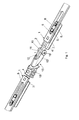
- FIG. 1 an axonometric view of an espagnolette fitting according to the invention with the forend removed
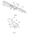
- Fig. 2 an axonometric representation of the espagnolette after Fig. 1 from below, with forend
- Fig. 3 an axonometric representation of a bolt
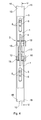
- Fig. 4 a section of the espagnolette fitting according to the line IV-IV in Fig. 5
- FIG. 5 a section along the line VV in Fig. 4 ,
- Fig. 1 schematically shows a drive rod fitting according to the invention. It is below an in Fig. 1 not shown Stulps 3 ( Fig. 2 ) a drive rod 1 slidably disposed. In this case, the drive rod 1 has an interruption 2. This interruption 2 is bridged by a web 4, which is upright or perpendicular to the rest of the drive rod 1 level. As a result, the two parts of the drive rod 1 are firmly connected.
- the two parts of the drive rod 1 are provided with openings 5, protrude into the lugs 6 of a guide and spacer body 7. These lugs 6 are shorter than the length of the apertures 5, so that the drive rod 1 can be moved relative to the guide and spacer bodies 7, which are screwed to the forend 3. For this purpose, the approaches 6 holes 8 for receiving screws.
- the guide and spacers 7 have grooves for receiving the web 4 and guide them. Furthermore, the guide and spacer body 7 serve to ensure a sufficient clearance between the facing sides of the forend 3 and the guide and spacer body 7 to allow a sufficiently easy displacement of the drive rod 1.
- the guide and spacers 7 are secured by screws, for which the holes 8 are provided at the bottom of a groove 10 in a frame of a window.
- the width of the guide and spacer body 7 corresponds to the width of the groove 10th
- an axis 11 is held on the legs 12 of a bolt 13 are pivotally held. These legs 12 of the bolt 13 are formed by a groove which is provided in this region of the bolt 13. In the retracted position of the bolt 13 ( Fig. 1 . Fig. 5 ) surrounds this groove the web. 4
- disk-like systems 15 are attached to the outer sides of the legs 12. These may be connected to the axis 11 or directly to the legs 12. It is essential that the free end faces of the systems 15 have a distance from each other, which corresponds to the width of the groove 10 ( Fig. 4 ), so that only a small amount of play remains between the systems 15 and the side walls 16 of the groove 10.
- Fig. 5 represented, which is opposite to in Fig. 1 and 2 example slightly modified embodiment shows, the diameter of the systems 15 to choose essentially the clear distance between the groove bottom 17 and the side facing the forend 3 accordingly.
- the systems 15 are aligned with the axis 11.
- the groove base 17 facing edges 22 of the legs 12 of the bolt 13 are curved convex and cooperate with a casserole block 18. This causes in a displacement of the drive rod 1 in Direction of arrow 19 ( Fig. 2 ) a deflection of the bolt 13 according to the arrow 21, whereby it passes through an opening 20 of the forend 3 and subsequently engages in a corresponding strike plate.
- the bolt 13 is pivoted due to the concave curved, the forend 3 facing edges 23 of the legs 12 through the edge of the opening 20 of the forend 3.
- the casserole block 18 is attached to the forend 3 and engages over the web 4, which connects the two parts of the drive rod 1.
Landscapes
- Engineering & Computer Science (AREA)
- Mechanical Engineering (AREA)
- Mutual Connection Of Rods And Tubes (AREA)
- Pivots And Pivotal Connections (AREA)
- Portable Nailing Machines And Staplers (AREA)
- Knitting Machines (AREA)
- Accommodation For Nursing Or Treatment Tables (AREA)
Applications Claiming Priority (1)
| Application Number | Priority Date | Filing Date | Title |
|---|---|---|---|
| AT11752009A AT508577B1 (de) | 2009-07-27 | 2009-07-27 | Treibstangenbeschlag |
Publications (2)
| Publication Number | Publication Date |
|---|---|
| EP2280141A2 true EP2280141A2 (fr) | 2011-02-02 |
| EP2280141A3 EP2280141A3 (fr) | 2012-10-31 |
Family
ID=43067122
Family Applications (1)
| Application Number | Title | Priority Date | Filing Date |
|---|---|---|---|
| EP10170579A Withdrawn EP2280141A3 (fr) | 2009-07-27 | 2010-07-23 | Ferrure de crémone |
Country Status (2)
| Country | Link |
|---|---|
| EP (1) | EP2280141A3 (fr) |
| AT (1) | AT508577B1 (fr) |
Citations (1)
| Publication number | Priority date | Publication date | Assignee | Title |
|---|---|---|---|---|
| DE102006000327A1 (de) | 2006-07-10 | 2008-01-24 | Aug. Winkhaus Gmbh & Co. Kg | Verschluss für einen Treibstangenbeschlag eines Fensters |
Family Cites Families (3)
| Publication number | Priority date | Publication date | Assignee | Title |
|---|---|---|---|---|
| AT315017B (de) * | 1972-03-14 | 1974-05-10 | Mayer & Co Riegel Beschlag | Verriegelungselement für Fenster, Türen od.dgl. |
| DE2425092A1 (de) * | 1974-05-24 | 1975-12-11 | Fuhr C Fa | Treibstangenverschluss fuer tueren, fenster oder dergleichen |
| CA2426191C (fr) * | 2000-10-19 | 2007-12-18 | Truth Hardware Corporation | Systeme de serrure multipoint |
-
2009
- 2009-07-27 AT AT11752009A patent/AT508577B1/de not_active IP Right Cessation
-
2010
- 2010-07-23 EP EP10170579A patent/EP2280141A3/fr not_active Withdrawn
Patent Citations (1)
| Publication number | Priority date | Publication date | Assignee | Title |
|---|---|---|---|---|
| DE102006000327A1 (de) | 2006-07-10 | 2008-01-24 | Aug. Winkhaus Gmbh & Co. Kg | Verschluss für einen Treibstangenbeschlag eines Fensters |
Also Published As
| Publication number | Publication date |
|---|---|
| EP2280141A3 (fr) | 2012-10-31 |
| AT508577A1 (de) | 2011-02-15 |
| AT508577B1 (de) | 2011-07-15 |
Similar Documents
| Publication | Publication Date | Title |
|---|---|---|
| DE2264353A1 (de) | Vorrichtung zur halterung eines ersatzrades eines motorfahrzeuges | |
| EP2273046A2 (fr) | Dispositif de verrouillage | |
| EP2380459B1 (fr) | Dispositif d'éjection | |
| DE69808572T2 (de) | Selbsttätige Nachstellvorrichtung für Handbremshebeln | |
| DE202011051957U1 (de) | Türfeststeller für Kraftfahrzeuge | |
| DE10217534A1 (de) | Verriegelungseinrichtung von Einstelleinrichtungen für Lenksäulen von Kraftfahrzeugen | |
| WO2010121588A2 (fr) | Bâti et armoire de commande montée sur ledit bâti | |
| DE2903635A1 (de) | Tuerbeschlag | |
| EP2578891B1 (fr) | Adapteur | |
| DE2138101A1 (de) | Oberlichtoeffner mit zwei spiegelbildlich angeordneten ausstellarmen | |
| EP2280141A2 (fr) | Ferrure de crémone | |
| DE202015106892U1 (de) | Rückenlehne eines Kraftfahrzeugsitzes | |
| DE102006029164B3 (de) | Kotflügelanordnung zur Abdeckung eines Fahrzeugrades | |
| EP2240651B1 (fr) | Dispositif de baguettes profilées | |
| EP3472493B1 (fr) | Dispositif de transmission de force | |
| DE10124709B4 (de) | Front für Kraftfahrzeuge | |
| DE202019106114U1 (de) | Türfeststeller für Nutzfahrzeugaufbauten | |
| DE102012222210A1 (de) | Zur verdeckten Anordnung vorgesehenes Ecklager | |
| DE4035856A1 (de) | Armlehne fuer einen kraftfahrzeugsitz | |
| DE202005005121U1 (de) | Treibstangenantrieb | |
| DE102006020108A1 (de) | Hubfenster | |
| DE202015006216U1 (de) | Verbindungsanordnung, damit ausgerüstetes Gestell, insbesondere Ladungsträger für Turmsegmente oder Rotorblätter von Windenergieanlagen, und Bausatz für das Gestell | |
| DE8522360U1 (de) | Containerverriegelung | |
| EP1186255A1 (fr) | Dispositif pour raccorder des plateaux de table à des pieds de table | |
| DE102015016687A1 (de) | Vorrichtung zum Schneiden von Belägen |
Legal Events
| Date | Code | Title | Description |
|---|---|---|---|
| PUAI | Public reference made under article 153(3) epc to a published international application that has entered the european phase |
Free format text: ORIGINAL CODE: 0009012 |
|
| AK | Designated contracting states |
Kind code of ref document: A2 Designated state(s): AL AT BE BG CH CY CZ DE DK EE ES FI FR GB GR HR HU IE IS IT LI LT LU LV MC MK MT NL NO PL PT RO SE SI SK SM TR |
|
| AX | Request for extension of the european patent |
Extension state: BA ME RS |
|
| PUAL | Search report despatched |
Free format text: ORIGINAL CODE: 0009013 |
|
| AK | Designated contracting states |
Kind code of ref document: A3 Designated state(s): AL AT BE BG CH CY CZ DE DK EE ES FI FR GB GR HR HU IE IS IT LI LT LU LV MC MK MT NL NO PL PT RO SE SI SK SM TR |
|
| AX | Request for extension of the european patent |
Extension state: BA ME RS |
|
| RIC1 | Information provided on ipc code assigned before grant |
Ipc: E05C 9/18 20060101AFI20120927BHEP |
|
| 17P | Request for examination filed |
Effective date: 20130114 |
|
| GRAP | Despatch of communication of intention to grant a patent |
Free format text: ORIGINAL CODE: EPIDOSNIGR1 |
|
| INTG | Intention to grant announced |
Effective date: 20170508 |
|
| STAA | Information on the status of an ep patent application or granted ep patent |
Free format text: STATUS: THE APPLICATION IS DEEMED TO BE WITHDRAWN |
|
| 18D | Application deemed to be withdrawn |
Effective date: 20170919 |