EP2280148A1 - Machine à fluide à volutes - Google Patents
Machine à fluide à volutes Download PDFInfo
- Publication number
- EP2280148A1 EP2280148A1 EP09730363A EP09730363A EP2280148A1 EP 2280148 A1 EP2280148 A1 EP 2280148A1 EP 09730363 A EP09730363 A EP 09730363A EP 09730363 A EP09730363 A EP 09730363A EP 2280148 A1 EP2280148 A1 EP 2280148A1
- Authority
- EP
- European Patent Office
- Prior art keywords
- spiral tooth
- scroll
- spiral
- disposed
- orbiting scroll
- Prior art date
- Legal status (The legal status is an assumption and is not a legal conclusion. Google has not performed a legal analysis and makes no representation as to the accuracy of the status listed.)
- Granted
Links
Images



Classifications
-
- F—MECHANICAL ENGINEERING; LIGHTING; HEATING; WEAPONS; BLASTING
- F04—POSITIVE - DISPLACEMENT MACHINES FOR LIQUIDS; PUMPS FOR LIQUIDS OR ELASTIC FLUIDS
- F04C—ROTARY-PISTON, OR OSCILLATING-PISTON, POSITIVE-DISPLACEMENT MACHINES FOR LIQUIDS; ROTARY-PISTON, OR OSCILLATING-PISTON, POSITIVE-DISPLACEMENT PUMPS
- F04C18/00—Rotary-piston pumps specially adapted for elastic fluids
- F04C18/02—Rotary-piston pumps specially adapted for elastic fluids of arcuate-engagement type, i.e. with circular translatory movement of co-operating members, each member having the same number of teeth or tooth-equivalents
- F04C18/0207—Rotary-piston pumps specially adapted for elastic fluids of arcuate-engagement type, i.e. with circular translatory movement of co-operating members, each member having the same number of teeth or tooth-equivalents both members having co-operating elements in spiral form
- F04C18/0246—Details concerning the involute wraps or their base, e.g. geometry
- F04C18/0253—Details concerning the base
- F04C18/0261—Details of the ports, e.g. location, number, geometry
-
- F—MECHANICAL ENGINEERING; LIGHTING; HEATING; WEAPONS; BLASTING
- F01—MACHINES OR ENGINES IN GENERAL; ENGINE PLANTS IN GENERAL; STEAM ENGINES
- F01C—ROTARY-PISTON OR OSCILLATING-PISTON MACHINES OR ENGINES
- F01C1/00—Rotary-piston machines or engines
- F01C1/02—Rotary-piston machines or engines of arcuate-engagement type, i.e. with circular translatory movement of co-operating members, each member having the same number of teeth or tooth-equivalents
- F01C1/0207—Rotary-piston machines or engines of arcuate-engagement type, i.e. with circular translatory movement of co-operating members, each member having the same number of teeth or tooth-equivalents both members having co-operating elements in spiral form
- F01C1/0215—Rotary-piston machines or engines of arcuate-engagement type, i.e. with circular translatory movement of co-operating members, each member having the same number of teeth or tooth-equivalents both members having co-operating elements in spiral form where only one member is moving
- F01C1/0223—Rotary-piston machines or engines of arcuate-engagement type, i.e. with circular translatory movement of co-operating members, each member having the same number of teeth or tooth-equivalents both members having co-operating elements in spiral form where only one member is moving with symmetrical double wraps
-
- F—MECHANICAL ENGINEERING; LIGHTING; HEATING; WEAPONS; BLASTING
- F04—POSITIVE - DISPLACEMENT MACHINES FOR LIQUIDS; PUMPS FOR LIQUIDS OR ELASTIC FLUIDS
- F04C—ROTARY-PISTON, OR OSCILLATING-PISTON, POSITIVE-DISPLACEMENT MACHINES FOR LIQUIDS; ROTARY-PISTON, OR OSCILLATING-PISTON, POSITIVE-DISPLACEMENT PUMPS
- F04C23/00—Combinations of two or more pumps, each being of rotary-piston or oscillating-piston type, specially adapted for elastic fluids; Pumping installations specially adapted for elastic fluids; Multi-stage pumps specially adapted for elastic fluids
- F04C23/008—Hermetic pumps
-
- F—MECHANICAL ENGINEERING; LIGHTING; HEATING; WEAPONS; BLASTING
- F04—POSITIVE - DISPLACEMENT MACHINES FOR LIQUIDS; PUMPS FOR LIQUIDS OR ELASTIC FLUIDS
- F04C—ROTARY-PISTON, OR OSCILLATING-PISTON, POSITIVE-DISPLACEMENT MACHINES FOR LIQUIDS; ROTARY-PISTON, OR OSCILLATING-PISTON, POSITIVE-DISPLACEMENT PUMPS
- F04C2250/00—Geometry
- F04C2250/10—Geometry of the inlet or outlet
Definitions
- the present invention relates to a scroll fluid machine that can be used as a compressor or expander in a refrigerating cycle for freezing or air conditioning, and in which an orbiting scroll is disposed between a pair of fixed scrolls so as to enable an orbiting motion, and particularly relates to a port construction that allows a working fluid to enter or leave a central chamber.
- double-sided scroll fluid machines are commonly-known in which spirals are disposed on two surfaces of a base plate of an orbiting scroll, the two spirals of the orbiting scroll are mated with respective spirals of fixed scrolls that are disposed on two sides of the orbiting scroll such that a compression chamber and an expansion chamber are formed on both sides of the orbiting scroll, and axial thrust loads that act on the orbiting scroll in the compression/expansion process are canceled out.
- spirals are formed on two surfaces of a base plate of an orbiting scroll, and a main shaft that drives or supports the orbiting scroll is supported at two ends by shaft bearing portions that are disposed centrally on the two fixed scrolls so as to pass through central portions of the spirals of the orbiting scroll.
- ports that are formed on bottom surfaces of winding start portions of the spirals of the fixed scrolls it is necessary for ports that are formed on bottom surfaces of winding start portions of the spirals of the fixed scrolls to be positioned outside an orbiting motion range of a boss portion of the orbiting scroll through which the main shaft passes.
- the winding start portions of the spirals of the fixed scrolls it is necessary for the winding start portions of the spirals of the fixed scrolls to be positioned partway along involute curves near outer circumferences of the shaft bearing portions, reducing efficiency. If attempts are made to ensure port aperture area by disposing the winding start portions of the spirals of the fixed scrolls closer to the starting points of the involute curves, the port openings interfere with the boss portion of
- double-sided scroll fluid machines have been proposed in which a peripheral wall surface near a scroll center of a spiral groove of a fixed scroll is formed into a semi-circular surface, a port opening is disposed on the semi-circular surface on an inner wall side of the spiral groove, an inner peripheral end of a spiral lap of an orbiting scroll slides in contact along the peripheral wall surface near the scroll center, and a working fluid is discharged through or sucked into the port opening (see Patent Document 1, for example).
- Patent Document 1 Japanese Patent Application Laid-Open JP-A-HEI 11-141 301 (Gazette)
- Patent Document 2 Japanese Patent Application Laid-Open JP-A-HEI 04-234 591 (Gazette)
- the present invention aims to solve the problems described above that result from port openings being formed on a bottom surface of a spiral groove by minimizing overlap between a layout of port openings that are formed on the bottom surface of the spiral groove and an orbiting motion range of a boss portion of an orbiting scroll,
- an object of the present invention is to provide a highly efficient and highly reliable scroll fluid machine by disposing ports that allow a working fluid to enter or leave a central chamber so as to have openings on a bottom surface of a spiral groove in a vicinity of a winding start end portion of a spiral tooth, and near an inward facing surface of the spiral tooth that is separated from the winding start end portion of the spiral tooth by an involute angle of approximately 90° to suppress fluctuations in port aperture area during each revolution of an orbiting scroll while ensuring port aperture area.
- a scroll fluid machine including:
- the ports that allow the working fluid to enter or leave are disposed on the first base plate and the second base plate so as to have openings in a vicinity of a winding start end portion of each of the first spiral tooth and the second spiral tooth, and near an inward facing surface of each of the first spiral tooth and the second spiral tooth at a position that is separated from the winding start end portion of each of the first spiral tooth and the second spiral tooth by an involute angle of approximately 90°.
- ports that allow a working fluid to enter or leave are disposed so as to have openings on a first base plate and a second base plate in a vicinity of winding start end portions of a first spiral tooth and a second spiral tooth, respectively, and near inward facing surfaces of the first spiral tooth and the second spiral tooth, respectively, at positions at an involute angle of approximately 90° away from the winding start end portions of the first spiral tooth and the second spiral tooth, respectively.
- the ports that allow the working fluid to enter or leave are disposed at two positions near the winding start end portions of the first spiral tooth and the second spiral tooth, respectively, sufficient port aperture area can be ensured without having to shift the winding start portions of the first spiral tooth and the second spiral tooth inordinately in the involute direction of the involute curves, and without inviting increases in dead volume due to cutting away the boss portion such as when two ports are disposed at symmetrical positions. Even if a portion of the opening of one port is blocked due to interference with the boss portion of the orbiting scroll as the orbiting scroll orbits, the other port will not interfere with the boss portion, reducing fluctuations in total aperture area of the ports during each revolution of the orbiting scroll. As a result, deterioration in efficiency due to significant pressure loss arising and occurrences of intermittent expansion steps can be suppressed, enabling high efficiency and high reliability to be achieved.
- FIG. 1 is a longitudinal section that shows a configuration of a scroll fluid machine according to a preferred embodiment of the present invention.
- parts that have been given identical numbering in the figure are identical or corresponding parts, and this practice is maintained throughout the specification.
- forms of components that appear throughout the specification are only examples and are not limited to these descriptions.
- the scroll fluid machine according to this embodiment is assumed to be used as a compressor-integrated expander in which a refrigerant (a working fluid) for which a high-pressure side is supercritical such as carbon dioxide is used, an expansion mechanism portion performs an expansion step in a refrigerating cycle, and a subcompression mechanism portion performs a portion of a compression step in the refrigerating cycle so as to be powered by mechanical energy that is recovered from the refrigerant in the expansion step.
- a refrigerant a working fluid
- a subcompression mechanism portion performs a portion of a compression step in the refrigerating cycle so as to be powered by mechanical energy that is recovered from the refrigerant in the expansion step.
- an expansion mechanism 2 is installed in a lower portion inside a sealed vessel 4 of a scroll expander 1, and a subcompression mechanism 3 is installed above the expansion mechanism 2.
- the expansion mechanism 2 is constituted by: a second fixed scroll 51 in which a second spiral tooth 51c is formed on an upper surface of a second base plate 51a; and an orbiting scroll 53 in which a lower spiral tooth 53c is formed on a lower surface of a third base plate 53a.
- the second spiral tooth 51c of the second fixed scroll 51 and the lower spiral tooth 53c of the orbiting scroll 53 have opposite winding directions, and are disposed so as to mesh with each other.
- the subcompression mechanism 3 is constituted by: a first fixed scroll 52 in which a first spiral tooth 52c is formed on a lower surface of a first base plate 52a; and an orbiting scroll 53 in which an upper spiral tooth 53d is formed on an upper surface of the third base plate 53a.
- the first spiral tooth 52c of the first fixed scroll 52 and the upper spiral tooth 53d of the orbiting scroll 53 have opposite winding directions, and are disposed so as to mesh with each other.
- a main shaft 78 is held rotatably at two ends by shaft bearing portions 51 b and 52b that are formed centrally on the second fixed scroll 51 of the expansion mechanism 2 and the first fixed scroll 52 of the subcompression mechanism 3, respectively.
- a sleeve 75 is fitted coaxially over a portion of the main shaft 78 that corresponds to a shaft bearing portion 51 b.
- a slider 74 is fitted into an orbiting shaft bearing portion 53b that is disposed centrally through the orbiting scroll 53.
- An eccentric shaft portion 80 that is formed on a central portion of the main shaft 78 is fitted into a shaft insertion aperture 81 that is disposed through the slider 74.
- a distance between an outside diameter center of the slider 74 and a central axis of the main shaft 78 can thereby fluctuate, and the slider 74 constitutes a variable radius crank mechanism that is moved in a direction in which orbiting radius is greatest by force from gas pressure that acts on the orbiting scroll 53, enabling the orbiting scroll 53 to perform orbital motion.
- An expansion suction pipe 15 that sucks in refrigerant and an expansion discharge pipe 16 that discharges expanded refrigerant are installed on side surfaces of the sealed vessel 4 outside the expansion mechanism 2.
- a subcompression suction pipe (not shown) that sucks in refrigerant and a subcompression discharge pipe 20 that discharges compressed refrigerant are installed on side surfaces of the sealed vessel 4 outside the subcompression mechanism 3.
- tip seals 71 that partition off a subcompression chamber 3a that is formed by the first spiral tooth 52c of the first fixed scroll 52 and the upper spiral tooth 53d of the orbiting scroll 53 are mounted to tips of the first spiral tooth 52c and the upper spiral tooth 53d of the first fixed scroll 52 and the orbiting scroll 53, respectively.
- An outer seal 73 that forms a seal between the orbiting scroll 53 and the first fixed scroll 52 is disposed on an outer circumference of the first spiral tooth 52c on a surface of the first fixed scroll 52 that faces the orbiting scroll 53.
- an inner seal 72 that forms a seal between the orbiting scroll 53 and the second fixed scroll 51 is disposed on an outer circumference of the orbiting shaft bearing portion 53b on a surface of the orbiting scroll 53 that faces the second fixed scroll 51.
- Tip seals 71 that partition off an expansion chamber 2a that is formed by the second spiral tooth 51c of the second fixed scroll 51 and the lower spiral tooth 53c of the orbiting scroll 53 are also mounted to tips of the second spiral tooth 51c of the second fixed scroll 51 and the lower spiral tooth 53c of the orbiting scroll 53.
- Autorotation of the orbiting scroll 53 is restricted by an Oldham ring 77 that is disposed near the subcompression mechanism 3.
- Upper and lower balancers 79a and 79b are mounted to two ends of the main shaft 78 in order to cancel out centrifugal forces that the orbiting scroll 53 generates by its orbiting motion.
- An oil pump 76 is mounted to a lower end of the main shaft 78, and supplies to each of the shaft bearing portions lubricating oil 9 that is stored in a bottom portion of a lower portion space of the sealed vessel 4.
- An oil gallery 78a that supplies oil mainly to the shaft bearing portion 51b, an oil gallery 78b that supplies oil to the shaft bearing portion 52b and the orbiting shaft bearing portion 53b, and a gas venting aperture 78c are disposed inside the main shaft 78.
- a spiral groove (not shown) is disposed on an outer circumferential surface of a portion of the main shaft 78 that corresponds to the shaft bearing portion 52b, and lubricating oil 9 that has been supplied to the shaft bearing portion 52b by means of the oil gallery 78b passes through the spiral groove and overflows into the upper portion space of the sealed vessel 4.
- Refrigerant that is to be subcompressed is supplied from a main compressor 5 by means of the subcompression suction pipe so as to include lubricating oil, is subcompressed by the orbiting scroll 53 and the first fixed scroll 52, is then separated from the oil by being opened to the upper portion space temporarily, and is discharged through the subcompression discharge pipe 20.
- the lubricating oil 9 that has overflowed from the shaft bearing portion 52b, and also that has been separated and accumulated in a lower portion of the upper portion space, is returned to the lower portion space by means of an oil return aperture 31.
- the subcompression mechanism 3 of the scroll expander 1 is disposed upstream from a gas cooler 11, and the expansion mechanism 2 is disposed downstream from the gas cooler 11.
- the expansion mechanism 2 is disposed upstream from an evaporator 12, and the subcompression mechanism 3 is disposed downstream from the main compressor 5 which is disposed downstream from the evaporator 12.
- a refrigerating cycle that is configured in this manner, when electric power is supplied to a motor 6, the main compressor 5 is driven, and refrigerant is compressed.
- the compressed refrigerant is conveyed into the subcompression mechanism 3 through the subcompression suction pipe, and is compressed and pressurized inside the subcompression chamber 3a that is formed by the first spiral tooth 52c of the first fixed scroll 52 and the upper spiral tooth 53d of the orbiting scroll 53.
- the refrigerant that has been compressed and pressurized inside the subcompression chamber 3a is discharged through the discharge valve 32, is opened to the upper portion space of the sealed vessel 4 temporarily and separated from the oil, is then discharged outside the sealed vessel 4 through the subcompression discharge pipe 20.
- the refrigerant that has been discharged through the subcompression discharge pipe 20 is conveyed into the gas cooler 11, and is cooled.
- the cooled refrigerant is conveyed through the expansion suction pipe 15 into the expansion mechanism 2, and is expanded and decompressed inside the expansion chamber 2a that is formed by the second spiral tooth 51 c of the second fixed scroll 51 and the lower spiral tooth 53c of the orbiting scroll 53.
- the refrigerant that has been expanded and decompressed inside the expansion chamber 2a is discharged through the expansion discharge pipe 16, is conveyed into the evaporator 12 and heated, and is then conveyed into the main compressor 5.
- FIG. 3 is a Mollier diagram that explains the operation of the refrigerating cycle, the vertical axis representing refrigerant pressure and the horizontal axis specific enthalpy. Moreover, FIG. 3 shows a case in which a refrigerant for which the high-pressure side is supercritical, such as CO 2 , is used.
- a refrigerant for which the high-pressure side is supercritical such as CO 2
- the refrigerant is compressed to an intermediate pressure Pm in the main compressor 5 (a to d').
- the refrigerant at intermediate pressure Pm that has been compressed by the main compressor 5 is conveyed into the subcompression chamber 3a of the subcompression mechanism 3 through the subcompression suction pipe, and is pressurized to a high pressure Ph (d' to d).
- the refrigerant that has been pressurized to the high pressure Ph is conveyed into the gas cooler 11 through the subcompression discharge pipe 20, and is cooled (d to c).
- the cooled refrigerant is conveyed into the expansion chamber 2a of the expansion mechanism 2 through the expansion suction pipe 15, and is expanded and decompressed to a low pressure Pl (c to b).
- the refrigerant that has been cooled by the gas cooler 11 were decompressed by a restrictor such as an expansion valve that does not recover power, it would decompress at a constant specific enthalpy from point c to point b'.
- the refrigerant is discharged through the expansion discharge pipe 16, is conveyed into the evaporator 12, and is heated (b to a). The heated refrigerant is conveyed into the main compressor 5.
- the expansion power that has been recovered by the expansion mechanism 2 is added to the compression power of the subcompression mechanism 3, and makes up for work proportionate to sliding loss that accompanies driving the orbiting scroll 53, the main shaft 78, the Oldham ring 77, etc.
- the subcompression chamber 3a of the subcompression mechanism 3 is at intermediate pressure Pm internally, and an outer circumferential side of the subcompression chamber 3a of the subcompression mechanism 3 is at low pressure Pl after expansion.
- the outer seal 73 that is disposed on the outer circumference of the first spiral tooth 52c on the surface of the first fixed scroll 52 that faces the orbiting scroll 53 forms a seal against internal and external differential pressure of the subcompression chamber 3a.
- the inner seal 72 that is disposed on the outer circumference of the orbiting shaft bearing portion 53b on the surface of the orbiting scroll 53 that faces the second fixed scroll 51 forms a seal against the differential pressure between the expansion chamber 2a and a side near the orbiting shaft bearing portion 53b.
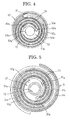
- FIG. 4 is a schematic diagram that shows a spiral tooth in a subcompression mechanism that can be used in the scroll fluid machine according to the preferred embodiment of the present invention and a layout thereof
- FIG. 5 is a schematic diagram that shows a spiral tooth in an expansion mechanism that can be used in the scroll fluid machine according to the preferred embodiment of the present invention and a layout thereof.
- FIGs. 4 and 5 show a state in which the orbiting radius of the orbiting scroll relative to the fixed scroll is 0.
- FIGs. 4 and 5 show the tooth end shapes of the spiral teeth of the fixed scroll and the orbiting scroll, respectively, as plans such that one is superimposed as a mirror image.
- FIGs. 6 and 7 are also similar.
- the first spiral tooth 52c and a first spiral groove 52d are formed spirally on the lower surface of the first base plate 52a of the first fixed scroll 52 in an involute curve shape on an inner circumferential side of the outer seal 73.
- the upper spiral tooth 53d and an upper spiral groove 53f are formed spirally on the upper surface of the third base plate 53a of the orbiting scroll 53 from a boss portion that surrounds a shaft bearing portion 53b, also known as a "bulbous portion" 53g.
- the first fixed scroll 52 and the orbiting scroll 53 are mated such that the first spiral tooth 52c and the upper spiral tooth 53d are accommodated inside the upper spiral groove 53f and the first spiral groove 52d.
- first spiral tooth 52c and the upper spiral tooth 53d are such that a mirror image of one has a similar shape that is phase-shifted by 180° from the other.
- Tip seals 71 are mounted into grooves that are formed on tooth ends of the first spiral tooth 52c and the upper spiral tooth 53d from a winding start to 1.5 winds.
- a discharge port 40b is disposed through the first base plate 52a so as to have an opening on a bottom surface of the first spiral groove 52d in a vicinity of a winding start end portion of the first spiral tooth 52c.
- a discharge port 40a is disposed through the first base plate 52a so as to have an opening on a bottom surface of the first spiral groove 52d near an inward facing surface of the first spiral tooth 52c at a position that is advanced from a winding start end portion of the first spiral tooth 52c by an involute angle of approximately 90°.
- the discharge ports 40a and 40b lead to the upper portion space of the sealed vessel 4 through the discharge valve 32.
- a suction port 39 is disposed through the first base plate 52a so as to have an opening on a bottom surface of the first spiral groove 52d in a vicinity of a winding finish end portion.
- the suction port 39 is connected to the subcompression suction pipe.
- the discharge port 40a has a rectilinear oblong aperture shape that is parallel to a peripheral wall surface near the inward facing surface of the first spiral tooth 52c, and the discharge port 40b has an approximately circular aperture shape.
- the rectilinear oblong shape has an external shape in which two ends of a pair of parallel straight lines are joined by semi circles, and that has a longitudinal axis in a direction that is parallel to the straight lines.
- an inner seal 72 is disposed on the lower surface of the third base plate 53a of the orbiting scroll 53 so as to surround the shaft bearing portion 53b on the bulbous portion 53g through which the shaft bearing portion 53b passes.
- the lower spiral tooth 53c and a lower spiral groove 53e are formed spirally on the lower surface of the third base plate 53a in the shape of involute curves from the bulbous portion 53g.
- the second spiral tooth 51c and a second spiral groove 51d are formed spirally on the upper surface of the second base plate 51a of the second fixed scroll 51 in an involute curve shape.
- the second fixed scroll 51 and the orbiting scroll 53 are mated such that the second spiral tooth 51c and the lower spiral tooth 53c are accommodated inside the lower spiral groove 53e and the second spiral groove 51d.
- the second spiral tooth 51c and the lower spiral tooth 53c are such that a mirror image of one has a similar shape that is phase-shifted by 180° from the other.
- Tip seals 71 are mounted into grooves that are formed on tooth ends of the second spiral tooth 51c and the lower spiral tooth 53c from a winding start to 1.5 winds.
- a suction port 35b is disposed through the second base plate 51a so as to have an opening on a bottom surface of the second spiral groove 51d in a vicinity of a winding start end portion of the second spiral tooth 51c.
- a suction port 35a is disposed through the second base plate 51a so as to have an opening on a bottom surface of the second spiral groove 51d near an inward facing surface of the second spiral tooth 51c at a position that is advanced from a winding start end portion of the second spiral tooth 51c by an involute angle of approximately 90°.
- the suction ports 35a and 35b are each connected to the expansion suction pipes 15 through conduits.
- the suction port 35a has a rectilinear oblong aperture shape that is parallel to a peripheral wall surface near the inward facing surface of the second spiral tooth 51c, and the suction port 35b has an approximately circular aperture shape.
- suction ports 35a and 35b and the discharge ports 40a and 40b are formed so as to have openings on bottom surfaces of the second spiral groove 51d and the first spiral groove 52d in this manner, the suction ports 35a and 35b and the discharge ports 40a and 40b can be formed on the second base plate 51a and the first base plate 52a so as to ensure sufficient aperture area.
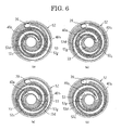
- FIG. 6 is a diagram that explains port obstruction due to the orbiting motion of the orbiting scroll in the subcompression mechanism of the scroll fluid machine according to the preferred embodiment of the present invention.
- FIG. 6(a) shows a time segment at which volume of an innermost chamber that is formed by the first spiral tooth 52c of the first fixed scroll 52 and the upper spiral tooth 53d of the orbiting scroll 53 is smallest.
- the orbiting scroll 53 revolves without rotating as shown in FIG. 6 at a constant turning radius around a center of the first fixed scroll 52 from (a) to (b) to (c) to (d) to (a). Volume of a sealed space that is formed by the first spiral tooth 52c and the upper spiral tooth 53d decreases as changes in volume occur due to relative motion between the first fixed scroll 52 and the orbiting scroll 53.
- working fluid that has been sucked in through the suction port 39 is continuously compressed, and is discharged through the discharge ports 40a and 40b.
- FIG. 6(b) there is a time segment in this orbiting motion of the orbiting scroll 53 at which one discharge port 40a is blocked due to interference with the bulbous portion 53g of the orbiting scroll 53.
- the other discharge port 40b is open and not blocked.
- a discharge port 40b is formed so as to be shifted from an involute starting point of a peripheral wall surface near an outward facing surface of the first spiral tooth 52c approximately 90° inward along a curved peripheral wall of a winding start end portion of the first spiral tooth 52c, and have an opening on a bottom surface of the first spiral groove 52d in close proximity to the curved peripheral wall at the winding start end portion of the first spiral tooth 52c.
- a discharge port 40a is formed so as to have an opening on a bottom surface of the first spiral groove 52d alongside a peripheral wall near an inward facing surface of the first spiral tooth 52c at a position that is advanced from a winding start end portion of the first spiral tooth 52c by an involute angle of approximately 90°.
- the discharge port 40a is formed so as to have a rectilinear oblong aperture shape that is parallel to a peripheral wall surface near the inward facing surface of the first spiral tooth 52c, and the discharge port 40b is formed so as to have an approximately circular aperture shape, aperture area when fully open can be increased while reducing the amount of blockage during interference with the bulbous portion 53g.
- FIG. 7 is a diagram that explains port obstruction due to the orbiting motion of the orbiting scroll in the expansion mechanism of the scroll fluid machine according to the preferred embodiment of the present invention.
- FIG. 7(a) shows a time segment when formation of a sealing point between an innermost chamber and a second chamber that are formed by the second spiral tooth 51c of the second fixed scroll 51 and the lower spiral tooth 53c of the orbiting scroll 53 is completed.
- the orbiting scroll 53 revolves without rotating as shown in FIG. 7 at a constant turning radius around a center of the second fixed scroll 51 from (a) to (b) to (c) to (d) to (a).
- Volume of a sealed space that is formed by the second spiral tooth 51c and the lower spiral tooth 53c increases as changes in volume occur due to relative motion between the second fixed scroll 51 and the orbiting scroll 53.
- a suction port 35b is formed so as to be shifted from an involute starting point of a peripheral wall surface near an outward facing surface of the second spiral tooth 51c approximately 90° inward along a curved peripheral wall of a winding start end portion of the second spiral tooth 51 c, and have an opening on a bottom surface of the second spiral groove 51 d in close proximity to the curved peripheral wall at the winding start end portion of the second spiral tooth 51c.
- a suction port 35a is formed so as to have an opening on a bottom surface of the second spiral groove 51d alongside a peripheral wall near an inward facing surface of the second spiral tooth 51c at a position that is advanced from a winding start end portion of the second spiral tooth 51c by an involute angle of approximately 90°.
- the suction port 35a is formed so as to have a rectilinear oblong aperture shape that is parallel to a peripheral wall surface near the inward facing surface of the second spiral tooth 51 c, and the suction port 35a is formed so as to have an approximately circular aperture shape, aperture area when fully open can be increased while reducing the amount of blockage during interference with the bulbous portion 53g.
- effects can also be similarly achieved by making the discharge port into two ports in the discharging process in the subcompression mechanism 3.
- ports that allow a working fluid to enter or leave are disposed so as to have openings on a first base plate and a second base plate in a vicinity of winding start end portions of a first spiral tooth and a second spiral tooth, respectively, and near inward facing surfaces of the first spiral tooth and the second spiral tooth, respectively, at positions that are separated by an involute angle of approximately 90° from the winding start end portions of the first spiral tooth and the second spiral tooth, respectively.
- an expansion mechanism 2 is configured in a lower portion inside a sealed vessel 4, and a subcompression mechanism 3 is configured in an upper portion inside the sealed vessel 4, but the subcompression mechanism 3 may also be configured in a lower portion inside the sealed vessel 4, and the expansion mechanism 2 configured in an upper portion inside the sealed vessel 4.
- a double-sided scroll-type compressor-integrated expander that performs expansion on one side, and that performs compression on the other side has been explained as a scroll fluid machine, but the present invention may also be applied to scroll fluid machines such as double-sided scroll-type compressors that perform compression on both sides, double-sided scroll-type expanders that perform expansion on both sides, etc.
- aperture shapes of the suction port 35a and the discharge port 40a are rectilinear oblong shapes, but the aperture shapes of the suction port 35a and the discharge port 40a need only be oblong shapes that have longitudinal axes that are parallel to peripheral wall surfaces near inward facing surfaces of the second spiral tooth 51 c and the first spiral tooth 52c, and, for example, may also be elliptical shapes, or oblong shapes that curve along the peripheral wall surfaces near the inward facing surfaces of the second spiral tooth 51c and the first spiral tooth 52c.
Landscapes
- Engineering & Computer Science (AREA)
- Mechanical Engineering (AREA)
- General Engineering & Computer Science (AREA)
- Rotary Pumps (AREA)
- Applications Or Details Of Rotary Compressors (AREA)
Applications Claiming Priority (2)
| Application Number | Priority Date | Filing Date | Title |
|---|---|---|---|
| JP2008099527 | 2008-04-07 | ||
| PCT/JP2009/050005 WO2009125608A1 (fr) | 2008-04-07 | 2009-01-05 | Machine à fluide à volutes |
Publications (3)
| Publication Number | Publication Date |
|---|---|
| EP2280148A1 true EP2280148A1 (fr) | 2011-02-02 |
| EP2280148A4 EP2280148A4 (fr) | 2015-03-18 |
| EP2280148B1 EP2280148B1 (fr) | 2018-09-12 |
Family
ID=41161744
Family Applications (1)
| Application Number | Title | Priority Date | Filing Date |
|---|---|---|---|
| EP09730363.0A Not-in-force EP2280148B1 (fr) | 2008-04-07 | 2009-01-05 | Machine à fluide à volutes |
Country Status (5)
| Country | Link |
|---|---|
| US (1) | US8475149B2 (fr) |
| EP (1) | EP2280148B1 (fr) |
| JP (1) | JP5138032B2 (fr) |
| CN (1) | CN101981274B (fr) |
| WO (1) | WO2009125608A1 (fr) |
Cited By (1)
| Publication number | Priority date | Publication date | Assignee | Title |
|---|---|---|---|---|
| WO2024194653A1 (fr) * | 2023-03-23 | 2024-09-26 | Edwards Limited | Pompe à spirale |
Families Citing this family (7)
| Publication number | Priority date | Publication date | Assignee | Title |
|---|---|---|---|---|
| JP5414811B2 (ja) * | 2010-01-19 | 2014-02-12 | 三菱電機株式会社 | 容積型膨張機及びこの容積型膨張機を用いた冷凍サイクル装置 |
| DK201200690A (en) * | 2012-11-06 | 2014-05-07 | Nissen Harry Stentoft | Co2 kompressor |
| US20140219844A1 (en) * | 2013-02-06 | 2014-08-07 | Daimler Ag | Expansion device for use in a working medium circuit and method for operating an expansion device |
| FR3006387B1 (fr) | 2013-05-31 | 2016-02-19 | Danfoss Commercial Compressors | Compresseur a spirale |
| FR3021075B1 (fr) * | 2014-05-16 | 2019-06-14 | Danfoss Commercial Compressors | Compresseur a spirales |
| CN113374531B (zh) * | 2021-07-27 | 2022-05-31 | 青岛科技大学 | 一体式喷油涡旋膨胀机 |
| CN116412134A (zh) * | 2021-12-31 | 2023-07-11 | 丹佛斯(天津)有限公司 | 压缩机 |
Family Cites Families (18)
| Publication number | Priority date | Publication date | Assignee | Title |
|---|---|---|---|---|
| JPS59119080A (ja) * | 1982-12-24 | 1984-07-10 | Hitachi Ltd | スクロ−ル圧縮機 |
| JPH0665878B2 (ja) * | 1985-12-28 | 1994-08-24 | 株式会社豊田自動織機製作所 | スクロ−ル型圧縮機 |
| JPS6359032A (ja) | 1986-08-27 | 1988-03-14 | Mitsubishi Electric Corp | バ−スト間搬送波周波数偏差補償回路 |
| DE69132650T2 (de) * | 1990-02-13 | 2002-05-08 | Anest Iwata Corp., Tokio/Tokyo | Spiralverdrängungsmaschine |
| JPH0730682B2 (ja) | 1990-03-23 | 1995-04-10 | 岩田塗装機工業株式会社 | スクロール式流体機械 |
| JP3235788B2 (ja) | 1990-03-23 | 2001-12-04 | アネスト岩田株式会社 | ツイン式スクロール流体機械 |
| JPH04234591A (ja) | 1991-01-08 | 1992-08-24 | Toshiba Corp | スクロ−ル形圧縮機 |
| JP3275901B2 (ja) | 1991-08-30 | 2002-04-22 | 東陶機器株式会社 | 静電チャックの設計方法 |
| EP0547491A1 (fr) * | 1991-12-16 | 1993-06-23 | Asea Brown Boveri Ag | Machine de déplacement de fluide du type à spirale |
| CN2143678Y (zh) * | 1992-12-19 | 1993-10-13 | 西安交通大学 | 带有防自转机构的涡旋式流体机械 |
| JPH07286586A (ja) * | 1994-04-20 | 1995-10-31 | Daikin Ind Ltd | スクロール型流体装置 |
| JP3591101B2 (ja) * | 1995-12-19 | 2004-11-17 | ダイキン工業株式会社 | スクロール形流体機械 |
| EP0899423B1 (fr) * | 1997-08-26 | 2002-12-11 | CRT Common Rail Technologies AG | Machine de déplacement de fluide du type à spirale |
| US7139304B2 (en) | 2001-08-10 | 2006-11-21 | Qualcomm Incorporated | Method and apparatus for controlling gain level of a communication channel in a CDMA communication system |
| JP4031222B2 (ja) * | 2001-09-21 | 2008-01-09 | アネスト岩田株式会社 | スクロール式流体機械 |
| JP2004346871A (ja) * | 2003-05-23 | 2004-12-09 | Anest Iwata Corp | スクロール流体機械 |
| US7160088B2 (en) * | 2003-09-25 | 2007-01-09 | Emerson Climate Technologies, Inc. | Scroll machine |
| CN1811134A (zh) * | 2005-01-24 | 2006-08-02 | 瑞智精密股份有限公司 | 涡卷式机器的轴向密封装置 |
-
2009
- 2009-01-05 EP EP09730363.0A patent/EP2280148B1/fr not_active Not-in-force
- 2009-01-05 JP JP2010507181A patent/JP5138032B2/ja not_active Expired - Fee Related
- 2009-01-05 US US12/935,470 patent/US8475149B2/en not_active Expired - Fee Related
- 2009-01-05 WO PCT/JP2009/050005 patent/WO2009125608A1/fr not_active Ceased
- 2009-01-05 CN CN200980111709.6A patent/CN101981274B/zh not_active Expired - Fee Related
Non-Patent Citations (1)
| Title |
|---|
| See references of WO2009125608A1 * |
Cited By (1)
| Publication number | Priority date | Publication date | Assignee | Title |
|---|---|---|---|---|
| WO2024194653A1 (fr) * | 2023-03-23 | 2024-09-26 | Edwards Limited | Pompe à spirale |
Also Published As
| Publication number | Publication date |
|---|---|
| CN101981274A (zh) | 2011-02-23 |
| JPWO2009125608A1 (ja) | 2011-08-04 |
| EP2280148A4 (fr) | 2015-03-18 |
| US20110027114A1 (en) | 2011-02-03 |
| EP2280148B1 (fr) | 2018-09-12 |
| CN101981274B (zh) | 2014-07-02 |
| WO2009125608A1 (fr) | 2009-10-15 |
| JP5138032B2 (ja) | 2013-02-06 |
| US8475149B2 (en) | 2013-07-02 |
Similar Documents
| Publication | Publication Date | Title |
|---|---|---|
| EP2280148B1 (fr) | Machine à fluide à volutes | |
| US7758326B2 (en) | Scroll fluid machine | |
| CN107208634A (zh) | 涡旋式压缩机 | |
| US11428229B2 (en) | Scroll compressor having enhanced discharge structure | |
| US9771937B2 (en) | Spiral compressor | |
| US20080298992A1 (en) | Scroll Expander | |
| JP4382151B2 (ja) | 2段ロータリ式膨張機、膨張機一体型圧縮機および冷凍サイクル装置 | |
| JP5304285B2 (ja) | スクロール圧縮機 | |
| US8092199B2 (en) | Scroll compressor including a plurality of shoulder sections | |
| CN105247214B (zh) | 压缩机 | |
| US10247188B2 (en) | Scroll compressor | |
| JP4512479B2 (ja) | スクロール圧縮機 | |
| JP2003343454A (ja) | スライドブッシュ及びスクロール型流体機械 | |
| JP6906887B2 (ja) | スクロール流体機械 | |
| JP4051596B2 (ja) | スクロール流体機械 | |
| CN111894852B (zh) | 涡旋式压缩机 | |
| JP2004316592A (ja) | スクロール圧縮機 | |
| JPH08261178A (ja) | スクロール形流体機械 | |
| JP2005163745A (ja) | スクロール圧縮機 | |
| EP4678917A1 (fr) | Machine à fluide de type à spirales | |
| JP5764715B2 (ja) | スクロール圧縮機 | |
| EP4596882A1 (fr) | Compresseur à spirale | |
| WO2019163628A1 (fr) | Machine à fluide à spirales | |
| JP4807056B2 (ja) | スクロール膨張機 | |
| JPH11280679A (ja) | スクロール圧縮機 |
Legal Events
| Date | Code | Title | Description |
|---|---|---|---|
| PUAI | Public reference made under article 153(3) epc to a published international application that has entered the european phase |
Free format text: ORIGINAL CODE: 0009012 |
|
| 17P | Request for examination filed |
Effective date: 20101019 |
|
| AK | Designated contracting states |
Kind code of ref document: A1 Designated state(s): AT BE BG CH CY CZ DE DK EE ES FI FR GB GR HR HU IE IS IT LI LT LU LV MC MK MT NL NO PL PT RO SE SI SK TR |
|
| AX | Request for extension of the european patent |
Extension state: AL BA RS |
|
| DAX | Request for extension of the european patent (deleted) | ||
| A4 | Supplementary search report drawn up and despatched |
Effective date: 20150212 |
|
| RIC1 | Information provided on ipc code assigned before grant |
Ipc: F04C 18/02 20060101ALI20150206BHEP Ipc: F01C 1/02 20060101AFI20150206BHEP Ipc: F01C 21/18 20060101ALI20150206BHEP Ipc: F01C 13/04 20060101ALI20150206BHEP |
|
| GRAP | Despatch of communication of intention to grant a patent |
Free format text: ORIGINAL CODE: EPIDOSNIGR1 |
|
| STAA | Information on the status of an ep patent application or granted ep patent |
Free format text: STATUS: GRANT OF PATENT IS INTENDED |
|
| INTG | Intention to grant announced |
Effective date: 20180328 |
|
| GRAS | Grant fee paid |
Free format text: ORIGINAL CODE: EPIDOSNIGR3 |
|
| GRAA | (expected) grant |
Free format text: ORIGINAL CODE: 0009210 |
|
| STAA | Information on the status of an ep patent application or granted ep patent |
Free format text: STATUS: THE PATENT HAS BEEN GRANTED |
|
| AK | Designated contracting states |
Kind code of ref document: B1 Designated state(s): AT BE BG CH CY CZ DE DK EE ES FI FR GB GR HR HU IE IS IT LI LT LU LV MC MK MT NL NO PL PT RO SE SI SK TR |
|
| REG | Reference to a national code |
Ref country code: GB Ref legal event code: FG4D |
|
| REG | Reference to a national code |
Ref country code: CH Ref legal event code: EP |
|
| REG | Reference to a national code |
Ref country code: IE Ref legal event code: FG4D |
|
| REG | Reference to a national code |
Ref country code: DE Ref legal event code: R096 Ref document number: 602009054461 Country of ref document: DE |
|
| REG | Reference to a national code |
Ref country code: AT Ref legal event code: REF Ref document number: 1040820 Country of ref document: AT Kind code of ref document: T Effective date: 20181015 |
|
| REG | Reference to a national code |
Ref country code: NL Ref legal event code: MP Effective date: 20180912 |
|
| REG | Reference to a national code |
Ref country code: LT Ref legal event code: MG4D |
|
| PG25 | Lapsed in a contracting state [announced via postgrant information from national office to epo] |
Ref country code: BG Free format text: LAPSE BECAUSE OF FAILURE TO SUBMIT A TRANSLATION OF THE DESCRIPTION OR TO PAY THE FEE WITHIN THE PRESCRIBED TIME-LIMIT Effective date: 20181212 Ref country code: LT Free format text: LAPSE BECAUSE OF FAILURE TO SUBMIT A TRANSLATION OF THE DESCRIPTION OR TO PAY THE FEE WITHIN THE PRESCRIBED TIME-LIMIT Effective date: 20180912 Ref country code: NO Free format text: LAPSE BECAUSE OF FAILURE TO SUBMIT A TRANSLATION OF THE DESCRIPTION OR TO PAY THE FEE WITHIN THE PRESCRIBED TIME-LIMIT Effective date: 20181212 Ref country code: FI Free format text: LAPSE BECAUSE OF FAILURE TO SUBMIT A TRANSLATION OF THE DESCRIPTION OR TO PAY THE FEE WITHIN THE PRESCRIBED TIME-LIMIT Effective date: 20180912 Ref country code: GR Free format text: LAPSE BECAUSE OF FAILURE TO SUBMIT A TRANSLATION OF THE DESCRIPTION OR TO PAY THE FEE WITHIN THE PRESCRIBED TIME-LIMIT Effective date: 20181213 Ref country code: SE Free format text: LAPSE BECAUSE OF FAILURE TO SUBMIT A TRANSLATION OF THE DESCRIPTION OR TO PAY THE FEE WITHIN THE PRESCRIBED TIME-LIMIT Effective date: 20180912 |
|
| PG25 | Lapsed in a contracting state [announced via postgrant information from national office to epo] |
Ref country code: HR Free format text: LAPSE BECAUSE OF FAILURE TO SUBMIT A TRANSLATION OF THE DESCRIPTION OR TO PAY THE FEE WITHIN THE PRESCRIBED TIME-LIMIT Effective date: 20180912 Ref country code: ES Free format text: LAPSE BECAUSE OF FAILURE TO SUBMIT A TRANSLATION OF THE DESCRIPTION OR TO PAY THE FEE WITHIN THE PRESCRIBED TIME-LIMIT Effective date: 20180912 Ref country code: LV Free format text: LAPSE BECAUSE OF FAILURE TO SUBMIT A TRANSLATION OF THE DESCRIPTION OR TO PAY THE FEE WITHIN THE PRESCRIBED TIME-LIMIT Effective date: 20180912 |
|
| REG | Reference to a national code |
Ref country code: AT Ref legal event code: MK05 Ref document number: 1040820 Country of ref document: AT Kind code of ref document: T Effective date: 20180912 |
|
| PG25 | Lapsed in a contracting state [announced via postgrant information from national office to epo] |
Ref country code: AT Free format text: LAPSE BECAUSE OF FAILURE TO SUBMIT A TRANSLATION OF THE DESCRIPTION OR TO PAY THE FEE WITHIN THE PRESCRIBED TIME-LIMIT Effective date: 20180912 Ref country code: NL Free format text: LAPSE BECAUSE OF FAILURE TO SUBMIT A TRANSLATION OF THE DESCRIPTION OR TO PAY THE FEE WITHIN THE PRESCRIBED TIME-LIMIT Effective date: 20180912 Ref country code: IS Free format text: LAPSE BECAUSE OF FAILURE TO SUBMIT A TRANSLATION OF THE DESCRIPTION OR TO PAY THE FEE WITHIN THE PRESCRIBED TIME-LIMIT Effective date: 20190112 Ref country code: PL Free format text: LAPSE BECAUSE OF FAILURE TO SUBMIT A TRANSLATION OF THE DESCRIPTION OR TO PAY THE FEE WITHIN THE PRESCRIBED TIME-LIMIT Effective date: 20180912 Ref country code: EE Free format text: LAPSE BECAUSE OF FAILURE TO SUBMIT A TRANSLATION OF THE DESCRIPTION OR TO PAY THE FEE WITHIN THE PRESCRIBED TIME-LIMIT Effective date: 20180912 Ref country code: IT Free format text: LAPSE BECAUSE OF FAILURE TO SUBMIT A TRANSLATION OF THE DESCRIPTION OR TO PAY THE FEE WITHIN THE PRESCRIBED TIME-LIMIT Effective date: 20180912 Ref country code: RO Free format text: LAPSE BECAUSE OF FAILURE TO SUBMIT A TRANSLATION OF THE DESCRIPTION OR TO PAY THE FEE WITHIN THE PRESCRIBED TIME-LIMIT Effective date: 20180912 Ref country code: CZ Free format text: LAPSE BECAUSE OF FAILURE TO SUBMIT A TRANSLATION OF THE DESCRIPTION OR TO PAY THE FEE WITHIN THE PRESCRIBED TIME-LIMIT Effective date: 20180912 |
|
| PG25 | Lapsed in a contracting state [announced via postgrant information from national office to epo] |
Ref country code: PT Free format text: LAPSE BECAUSE OF FAILURE TO SUBMIT A TRANSLATION OF THE DESCRIPTION OR TO PAY THE FEE WITHIN THE PRESCRIBED TIME-LIMIT Effective date: 20190112 Ref country code: SK Free format text: LAPSE BECAUSE OF FAILURE TO SUBMIT A TRANSLATION OF THE DESCRIPTION OR TO PAY THE FEE WITHIN THE PRESCRIBED TIME-LIMIT Effective date: 20180912 |
|
| REG | Reference to a national code |
Ref country code: DE Ref legal event code: R097 Ref document number: 602009054461 Country of ref document: DE |
|
| PLBE | No opposition filed within time limit |
Free format text: ORIGINAL CODE: 0009261 |
|
| STAA | Information on the status of an ep patent application or granted ep patent |
Free format text: STATUS: NO OPPOSITION FILED WITHIN TIME LIMIT |
|
| PG25 | Lapsed in a contracting state [announced via postgrant information from national office to epo] |
Ref country code: DK Free format text: LAPSE BECAUSE OF FAILURE TO SUBMIT A TRANSLATION OF THE DESCRIPTION OR TO PAY THE FEE WITHIN THE PRESCRIBED TIME-LIMIT Effective date: 20180912 |
|
| 26N | No opposition filed |
Effective date: 20190613 |
|
| PG25 | Lapsed in a contracting state [announced via postgrant information from national office to epo] |
Ref country code: SI Free format text: LAPSE BECAUSE OF FAILURE TO SUBMIT A TRANSLATION OF THE DESCRIPTION OR TO PAY THE FEE WITHIN THE PRESCRIBED TIME-LIMIT Effective date: 20180912 Ref country code: MC Free format text: LAPSE BECAUSE OF FAILURE TO SUBMIT A TRANSLATION OF THE DESCRIPTION OR TO PAY THE FEE WITHIN THE PRESCRIBED TIME-LIMIT Effective date: 20180912 |
|
| REG | Reference to a national code |
Ref country code: CH Ref legal event code: PL |
|
| PG25 | Lapsed in a contracting state [announced via postgrant information from national office to epo] |
Ref country code: LU Free format text: LAPSE BECAUSE OF NON-PAYMENT OF DUE FEES Effective date: 20190105 |
|
| REG | Reference to a national code |
Ref country code: BE Ref legal event code: MM Effective date: 20190131 |
|
| REG | Reference to a national code |
Ref country code: IE Ref legal event code: MM4A |
|
| PG25 | Lapsed in a contracting state [announced via postgrant information from national office to epo] |
Ref country code: FR Free format text: LAPSE BECAUSE OF NON-PAYMENT OF DUE FEES Effective date: 20190131 |
|
| PG25 | Lapsed in a contracting state [announced via postgrant information from national office to epo] |
Ref country code: BE Free format text: LAPSE BECAUSE OF NON-PAYMENT OF DUE FEES Effective date: 20190131 |
|
| PG25 | Lapsed in a contracting state [announced via postgrant information from national office to epo] |
Ref country code: CH Free format text: LAPSE BECAUSE OF NON-PAYMENT OF DUE FEES Effective date: 20190131 Ref country code: LI Free format text: LAPSE BECAUSE OF NON-PAYMENT OF DUE FEES Effective date: 20190131 |
|
| PG25 | Lapsed in a contracting state [announced via postgrant information from national office to epo] |
Ref country code: IE Free format text: LAPSE BECAUSE OF NON-PAYMENT OF DUE FEES Effective date: 20190105 |
|
| PG25 | Lapsed in a contracting state [announced via postgrant information from national office to epo] |
Ref country code: TR Free format text: LAPSE BECAUSE OF FAILURE TO SUBMIT A TRANSLATION OF THE DESCRIPTION OR TO PAY THE FEE WITHIN THE PRESCRIBED TIME-LIMIT Effective date: 20180912 |
|
| PG25 | Lapsed in a contracting state [announced via postgrant information from national office to epo] |
Ref country code: MT Free format text: LAPSE BECAUSE OF NON-PAYMENT OF DUE FEES Effective date: 20190105 |
|
| PG25 | Lapsed in a contracting state [announced via postgrant information from national office to epo] |
Ref country code: CY Free format text: LAPSE BECAUSE OF FAILURE TO SUBMIT A TRANSLATION OF THE DESCRIPTION OR TO PAY THE FEE WITHIN THE PRESCRIBED TIME-LIMIT Effective date: 20180912 |
|
| PG25 | Lapsed in a contracting state [announced via postgrant information from national office to epo] |
Ref country code: HU Free format text: LAPSE BECAUSE OF FAILURE TO SUBMIT A TRANSLATION OF THE DESCRIPTION OR TO PAY THE FEE WITHIN THE PRESCRIBED TIME-LIMIT; INVALID AB INITIO Effective date: 20090105 |
|
| PGFP | Annual fee paid to national office [announced via postgrant information from national office to epo] |
Ref country code: GB Payment date: 20211206 Year of fee payment: 14 |
|
| PGFP | Annual fee paid to national office [announced via postgrant information from national office to epo] |
Ref country code: DE Payment date: 20211130 Year of fee payment: 14 |
|
| PG25 | Lapsed in a contracting state [announced via postgrant information from national office to epo] |
Ref country code: MK Free format text: LAPSE BECAUSE OF FAILURE TO SUBMIT A TRANSLATION OF THE DESCRIPTION OR TO PAY THE FEE WITHIN THE PRESCRIBED TIME-LIMIT Effective date: 20180912 |
|
| REG | Reference to a national code |
Ref country code: DE Ref legal event code: R119 Ref document number: 602009054461 Country of ref document: DE |
|
| GBPC | Gb: european patent ceased through non-payment of renewal fee |
Effective date: 20230105 |
|
| PG25 | Lapsed in a contracting state [announced via postgrant information from national office to epo] |
Ref country code: GB Free format text: LAPSE BECAUSE OF NON-PAYMENT OF DUE FEES Effective date: 20230105 Ref country code: DE Free format text: LAPSE BECAUSE OF NON-PAYMENT OF DUE FEES Effective date: 20230801 |