EP2280227A2 - système pour stocker et récupérer la chaleur - Google Patents
système pour stocker et récupérer la chaleur Download PDFInfo
- Publication number
- EP2280227A2 EP2280227A2 EP10168518A EP10168518A EP2280227A2 EP 2280227 A2 EP2280227 A2 EP 2280227A2 EP 10168518 A EP10168518 A EP 10168518A EP 10168518 A EP10168518 A EP 10168518A EP 2280227 A2 EP2280227 A2 EP 2280227A2
- Authority
- EP
- European Patent Office
- Prior art keywords
- heat
- storage
- heat storage
- line
- evaporator
- Prior art date
- Legal status (The legal status is an assumption and is not a legal conclusion. Google has not performed a legal analysis and makes no representation as to the accuracy of the status listed.)
- Withdrawn
Links
- XLYOFNOQVPJJNP-UHFFFAOYSA-N water Substances O XLYOFNOQVPJJNP-UHFFFAOYSA-N 0.000 claims abstract description 24
- 238000009434 installation Methods 0.000 claims abstract description 3
- 238000005338 heat storage Methods 0.000 claims description 86
- 239000003507 refrigerant Substances 0.000 claims description 23
- 239000003990 capacitor Substances 0.000 claims description 15
- 239000002184 metal Substances 0.000 claims description 4
- 238000006243 chemical reaction Methods 0.000 claims description 3
- 230000008018 melting Effects 0.000 claims description 3
- 238000002844 melting Methods 0.000 claims description 3
- 238000004891 communication Methods 0.000 claims description 2
- 238000009833 condensation Methods 0.000 claims description 2
- 230000005494 condensation Effects 0.000 claims description 2
- 239000012530 fluid Substances 0.000 claims description 2
- 238000010438 heat treatment Methods 0.000 description 13
- 239000003795 chemical substances by application Substances 0.000 description 11
- 239000007788 liquid Substances 0.000 description 9
- 239000002918 waste heat Substances 0.000 description 9
- 239000013529 heat transfer fluid Substances 0.000 description 6
- 238000004804 winding Methods 0.000 description 4
- 229920005830 Polyurethane Foam Polymers 0.000 description 2
- 230000005611 electricity Effects 0.000 description 2
- 238000001704 evaporation Methods 0.000 description 2
- 230000006870 function Effects 0.000 description 2
- 239000003673 groundwater Substances 0.000 description 2
- 239000011496 polyurethane foam Substances 0.000 description 2
- 238000010276 construction Methods 0.000 description 1
- 239000013078 crystal Substances 0.000 description 1
- 238000002425 crystallisation Methods 0.000 description 1
- 230000008025 crystallization Effects 0.000 description 1
- 230000008020 evaporation Effects 0.000 description 1
- 239000000284 extract Substances 0.000 description 1
- 230000002349 favourable effect Effects 0.000 description 1
- 239000013505 freshwater Substances 0.000 description 1
- 238000009413 insulation Methods 0.000 description 1
- 238000002156 mixing Methods 0.000 description 1
- 239000012188 paraffin wax Substances 0.000 description 1
- 230000000630 rising effect Effects 0.000 description 1
- 150000003839 salts Chemical class 0.000 description 1
- 229920006395 saturated elastomer Polymers 0.000 description 1
- 239000013535 sea water Substances 0.000 description 1
- 239000007787 solid Substances 0.000 description 1
- 229910001220 stainless steel Inorganic materials 0.000 description 1
- 239000010935 stainless steel Substances 0.000 description 1
- 238000013517 stratification Methods 0.000 description 1
- 239000002351 wastewater Substances 0.000 description 1
Images


Classifications
-
- F—MECHANICAL ENGINEERING; LIGHTING; HEATING; WEAPONS; BLASTING
- F24—HEATING; RANGES; VENTILATING
- F24D—DOMESTIC- OR SPACE-HEATING SYSTEMS, e.g. CENTRAL HEATING SYSTEMS; DOMESTIC HOT-WATER SUPPLY SYSTEMS; ELEMENTS OR COMPONENTS THEREFOR
- F24D11/00—Central heating systems using heat accumulated in storage masses
- F24D11/02—Central heating systems using heat accumulated in storage masses using heat pumps
- F24D11/0214—Central heating systems using heat accumulated in storage masses using heat pumps water heating system
- F24D11/0221—Central heating systems using heat accumulated in storage masses using heat pumps water heating system combined with solar energy
-
- F—MECHANICAL ENGINEERING; LIGHTING; HEATING; WEAPONS; BLASTING
- F24—HEATING; RANGES; VENTILATING
- F24H—FLUID HEATERS, e.g. WATER OR AIR HEATERS, HAVING HEAT-GENERATING MEANS, e.g. HEAT PUMPS, IN GENERAL
- F24H7/00—Storage heaters, i.e. heaters in which the energy is stored as heat in masses for subsequent release
- F24H7/02—Storage heaters, i.e. heaters in which the energy is stored as heat in masses for subsequent release the released heat being conveyed to a transfer fluid
- F24H7/04—Storage heaters, i.e. heaters in which the energy is stored as heat in masses for subsequent release the released heat being conveyed to a transfer fluid with forced circulation of the transfer fluid
-
- Y—GENERAL TAGGING OF NEW TECHNOLOGICAL DEVELOPMENTS; GENERAL TAGGING OF CROSS-SECTIONAL TECHNOLOGIES SPANNING OVER SEVERAL SECTIONS OF THE IPC; TECHNICAL SUBJECTS COVERED BY FORMER USPC CROSS-REFERENCE ART COLLECTIONS [XRACs] AND DIGESTS
- Y02—TECHNOLOGIES OR APPLICATIONS FOR MITIGATION OR ADAPTATION AGAINST CLIMATE CHANGE
- Y02B—CLIMATE CHANGE MITIGATION TECHNOLOGIES RELATED TO BUILDINGS, e.g. HOUSING, HOUSE APPLIANCES OR RELATED END-USER APPLICATIONS
- Y02B10/00—Integration of renewable energy sources in buildings
- Y02B10/20—Solar thermal
-
- Y—GENERAL TAGGING OF NEW TECHNOLOGICAL DEVELOPMENTS; GENERAL TAGGING OF CROSS-SECTIONAL TECHNOLOGIES SPANNING OVER SEVERAL SECTIONS OF THE IPC; TECHNICAL SUBJECTS COVERED BY FORMER USPC CROSS-REFERENCE ART COLLECTIONS [XRACs] AND DIGESTS
- Y02—TECHNOLOGIES OR APPLICATIONS FOR MITIGATION OR ADAPTATION AGAINST CLIMATE CHANGE
- Y02B—CLIMATE CHANGE MITIGATION TECHNOLOGIES RELATED TO BUILDINGS, e.g. HOUSING, HOUSE APPLIANCES OR RELATED END-USER APPLICATIONS
- Y02B10/00—Integration of renewable energy sources in buildings
- Y02B10/40—Geothermal heat-pumps
-
- Y—GENERAL TAGGING OF NEW TECHNOLOGICAL DEVELOPMENTS; GENERAL TAGGING OF CROSS-SECTIONAL TECHNOLOGIES SPANNING OVER SEVERAL SECTIONS OF THE IPC; TECHNICAL SUBJECTS COVERED BY FORMER USPC CROSS-REFERENCE ART COLLECTIONS [XRACs] AND DIGESTS
- Y02—TECHNOLOGIES OR APPLICATIONS FOR MITIGATION OR ADAPTATION AGAINST CLIMATE CHANGE
- Y02B—CLIMATE CHANGE MITIGATION TECHNOLOGIES RELATED TO BUILDINGS, e.g. HOUSING, HOUSE APPLIANCES OR RELATED END-USER APPLICATIONS
- Y02B10/00—Integration of renewable energy sources in buildings
- Y02B10/70—Hybrid systems, e.g. uninterruptible or back-up power supplies integrating renewable energies
-
- Y—GENERAL TAGGING OF NEW TECHNOLOGICAL DEVELOPMENTS; GENERAL TAGGING OF CROSS-SECTIONAL TECHNOLOGIES SPANNING OVER SEVERAL SECTIONS OF THE IPC; TECHNICAL SUBJECTS COVERED BY FORMER USPC CROSS-REFERENCE ART COLLECTIONS [XRACs] AND DIGESTS
- Y02—TECHNOLOGIES OR APPLICATIONS FOR MITIGATION OR ADAPTATION AGAINST CLIMATE CHANGE
- Y02E—REDUCTION OF GREENHOUSE GAS [GHG] EMISSIONS, RELATED TO ENERGY GENERATION, TRANSMISSION OR DISTRIBUTION
- Y02E60/00—Enabling technologies; Technologies with a potential or indirect contribution to GHG emissions mitigation
- Y02E60/14—Thermal energy storage
Definitions
- the invention relates to a system for storing and reusing heat.
- the heat source e.g. Solar energy, geothermal, groundwater, seawater, wastewater or waste heat from industrial plants into consideration. These heat sources are developed with the help of heat collectors. Solar energy is collected with solar panels.
- a disadvantage of solar energy for example, that energy can be supplied to the heat storage only when the temperature of the solar collector is much higher than the temperature of the heat storage.
- Heat sources that provide a lower temperature such as Geothermal heat, groundwater, solar energy on cloudy days, can not be exhausted.
- heat pumps are typically used, e.g. Geothermal heating systems.
- the object is achieved by providing a system for storing and reusing heat.
- the system according to the invention comprises a heat collector, a first heat accumulator with a first storage medium and a second heat accumulator with a second storage medium,
- the system is characterized in that the heat collector feeds at least the first heat accumulator via a collector line, the first heat accumulator to which the second heat accumulator is connected via a heat pump arrangement, the heat pump arrangement at least one compressor, an evaporator, a condenser, and an expansion valve, the first heat storage containing the evaporator and the second heat storage, the capacitor.
- the first heat accumulator typically has a lower temperature than the second heat accumulator.
- the first heat accumulator can thus be supplied with heat by a collector, which has a relatively low temperature.
- the Heat pump assembly again withdraws heat from the first heat storage at low temperature and supplies heat to the second heat storage at a higher temperature.
- power losses occur. Characterized in that the first heat storage directly to the evaporator of the heat pump assembly and the second heat storage directly to the condenser of the heat pump assembly, these power losses can be efficiently avoided.
- heat supplied by a low temperature collector can be led into a first heat storage and stored there at low temperature, which has the advantage that the waste heat losses remain low. If necessary (for example, when the storage temperature of the second storage has fallen below a certain value), heat is extracted from the first heat storage by means of the heat pump and supplied to the second heat storage at a higher temperature.
- At least the first heat storage is a latent heat storage and contains as the first storage medium phase conversion means.
- This phase-change agent may in the simplest case be water or a special phase change agent usually consisting of paraffins.
- the significant increase in volume in the conversion of liquid water to ice must be considered for the construction of the first heat storage. This can e.g. be done by appropriate expansion creases are provided in the shell of the heat accumulator.
- phase change agents are used wherein the softening point or melting point of the Phase change agent is in the range between -10 ° C and 25 ° C.
- Parafin-containing phase change agents have been found to be advantageous in this area.
- salts with a high crystal water content are used, which dissolve at higher temperature in their own water of crystallization.
- An embodiment is characterized in that the evaporator comprises an evaporator line which leads through the first heat accumulator, wherein the refrigerant is guided in the interior of the evaporator line, and that the outer wall of the evaporator line directly touches the first storage medium. As a result, heat can be withdrawn directly from the first storage medium by evaporating the refrigerant.
- At least a part of the evaporator line, which is located in the first heat storage, as corrugated hose (preferably metal corrugated hose) is formed.
- corrugated hose preferably metal corrugated hose
- the part of the evaporator line coming from the expansion valve is guided in an outer area of the first heat store, and the part of the evaporator line leading to the compressor is guided in an inner area, wherein the outer area outside the inner area is around the inner area ,
- the condenser comprises a condenser duct (designed for a pressure of at least 10 bar) passing through the second heat accumulator, wherein a refrigerant is led inside the condenser duct, and the outer wall of the condenser duct directly contacts the storage medium (e.g., water).
- a refrigerant is led inside the condenser duct, and the outer wall of the condenser duct directly contacts the storage medium (e.g., water).
- At least part of the capacitor line, which is located in the second heat storage, as a corrugated hose (preferably metal corrugated hose) is formed.
- a corrugated hose preferably metal corrugated hose
- the expansion valve and compressor are set or selected to provide a pressure in the evaporator conduit that results in an evaporative temperature of the refrigerant that is less than 15K from the melting point or softening point of the phase change agent.
- a controller may be provided which controls the compressor and / or the expansion valve as a function of the temperature measured at a measuring point of the second heat accumulator.
- the expansion valve and the compressor may be set or selected to provide a pressure in the condenser conduit that results in a refrigerant condensation temperature that is less than 15K from the temperature measured at a second heat accumulator sensing point.
- the heat source can also feed the second heat storage, wherein corresponding lines and valves are provided and a controller is provided which switches these valves. This results in the possibility that when the heat collector is at a higher temperature, this heat can be passed directly into the second heat storage.
- a controller which can be switched back and forth between the first heat storage and the second heat storage depending on the temperature that provides the heat collector available.
- valves (or pumps) and a controller for switching the valves (or pumps) may be provided, which are the collector line from the second heat storage comes, with the collector line, which feeds the first heat storage, connects.
- the first heat accumulator can be equipped with an additional heater to raise the temperature of the first storage medium by 1-5K, which can significantly increase the efficiency of the heat pump assembly.
- Another aspect of the invention relates to a heat exchanger for installation in the second heat storage for one of the systems.
- Such a heat exchanger is advantageously characterized in that it comprises a shell with openings, so that the part of the heat exchanger, which includes the capacitor line, is in direct fluid communication with the storage medium of the second heat storage.
- the storage medium of the second accumulator driven by the heat convection, can flow in the manner of a chimney through the heat exchanger, which increases the performance of the heat exchanger.
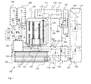
- Fig. 1 shows a schematic representation of a flow chart of an embodiment according to the invention.
- Fig. 2 shows an oblique view of the heat storage with heat pump and domestic water module.
- Fig. 3a shows a perspective view of a module of a latent heat storage
- Fig. 3b shows an additional heater for a module of a latent heat storage
- Fig. 4a-b show different views of a first heat exchanger of the second heat storage
- the system 100 ( Fig. 1 ) consists of a latent heat storage (first heat storage, cold storage) 110, a hot water tank (second heat storage, warm storage) 120, a heat pump 130, a solar system 140, an optional burner 150, an optional waste heat source 160, a water heater with control 170, a Hot water module 180, optional high temperature heating with 185 heating control and low temperature heating 190
- the latent heat storage (first heat storage, cold storage) 110 consists of a plurality (e.g., 8 pieces) of storage modules 111, each storage module containing approximately 50 liters of storage medium (phase change means).
- the latent heat storage serves to store heat at low temperature, e.g. from a waste heat source 160 via the waste heat pipe 162 or from the solar plant 140 via the solar pipe 142 (e.g., in cloudy weather).
- the latent heat storage is typically charged at temperatures in the range of 0 ° C and 30 ° C.
- the latent heat storage 110 can be charged via the return line 147 from the second heat exchanger 124.
- the first heat accumulator can also be heated via an additional heater 119 (for example electric infrared heater), which can preferably take place via electricity at a favorable tariff (for example so-called nighttime electricity).
- the heat in the latent heat storage is supplied via the storage line 112.
- the return line from the latent heat storage is the storage line 114.
- the control which specifies the heat source for the latent heat storage 110, via the valve group 145th
- the hot water tank 120 is the second heat storage or the hot storage.
- a first heat exchanger 122 which includes the condenser of the heat pump, and a second heat exchanger 124 are included.
- a plurality of distributor bells 129 is disposed within the heat exchanger.
- the heat pump 130 includes at least the compressor, the expansion valve, and a controller for controlling the compressor and the expansion valve.
- a refrigerant is compressed and via the condenser line 131 from the compressor to Condenser, which is located in the first heat exchanger 122 in the second heat storage 120, out.
- the refrigerant condenses on the inner wall of the capacitor line and thus directly transfers the heat to the second heat store 120.
- the liquefied refrigerant then flows via the condenser line 132 from the condenser to the expansion valve.
- the adiabatic expansion cools the refrigerant.
- the suction pressure is adjusted by the control of the compressor in the heat pump so that the saturated steam temperature of the refrigerant is below the temperature of the first heat exchanger.
- the refrigerant is passed via the evaporator line 133 from the expansion valve to the evaporator.
- the evaporator which is the element of the second heat storage, heat is directly transferred from the second storage medium to the refrigerant and leads to evaporation of the refrigerant.
- the vaporized refrigerant is in turn passed via the evaporator line 134 to the compressor and compressed there.
- the solar system 140 includes at least the solar panels 141 and a pump group with associated control.
- the liquid circuit of the solar panels can be separated from the storage circuit (142, 144) and connected via a heat exchanger.
- the heat is supplied via the solar line 142 and the heat storage (110, 120), wherein the storage line 144 returns the heat transfer fluid to the solar system.
- the heat from the solar system is guided via the storage line 146 to the second heat exchanger 124 and delivered there to the second heat storage 120.
- the flow of the heat transfer fluid is controlled so that either the first heat storage 110 or the second heat storage 120 or the second is fed to the first heat storage.
- the optional burner 150 directly supplies the high temperature heating circuit 185, the low temperature heating circuit 190 and / or the second heat storage 120 via the burner lines (feed line 152, return line 154).
- the flow temperature for the High temperature heating circuit is in the range of 30 ° C to 80 ° C, while the flow temperature for the low temperature heating circuit is in the range of 25 ° C to 40 ° C.
- the two heating circuits remove the heat transfer fluid by means of the pump groups assigned to the respective heating circuit. If the burner 150 is not in operation, or if no burner is connected, remove the two heating circuits, the heat required from the Hochtemperaturtechnisch- ie the second heat storage 120th
- the optional waste heat source 160 (e.g., from engine waste heat) supplies the first heat storage 110 or the second heat storage 120 via the waste heat conduit 162, depending on the available temperature.
- the line 164 leads the heat transfer fluid back to the waste heat source 160th
- Domestic hot water 170 provides heat for the service water from the hot storage (second heat storage 120) via lines 172 and 182, with line 172 extracting heat from the head of the second, higher temperature heat storage and line 182 removing the heat at low temperature extracts. With the aid of the regulation 173, a mixing valve is controlled as a function of the available temperatures in the lines 172 and 182. If the temperature at the top of the second heat exchanger is too low, the water heater 171 is connected.
- the service water module 180 heats the fresh water coming from line 186 via a heat exchanger.
- the hot water is then available to the hot water dispenser 181 (e.g., shower).
- Fig. 2 shows an oblique view of the heat storage with heat pump 230 and domestic water module 270.
- Eight latent heat storage 211 are horizontally arranged in two superimposed groups of four modules 211.
- the latent heat storage 211 are parallel both with respect to the supply of solar heat and with respect to the connections to the heat pump switched. Both capacitor lines and solar lines, each from and to the latent heat storage, are led from the same page in the latent heat storage.
- Fig. 3a shows a latent heat storage 311, so you can see the wiring within the latent heat storage.
- the latent heat accumulator 311 consists of a cylinder 317 which is surrounded by a heat insulation 313 (eg a Dewar vessel encased with polyurethane foam or only a polyurethane foam sheath).
- the coming from the heat source storage line 312 is guided from the cylinder cover into the core of the cylinder to the cylinder bottom and wound from there in helical form in the outer third of the cylinder (ie near the cylinder jacket) back to the cylinder cover and guided as a storage line 314 back to the heat source.
- the evaporator line 333 is wound from the expansion valve coming in helical form led to the cylinder bottom and parallel to the wound in helical shape memory line, resulting in a kind of double helix 318. Then the evaporator line is guided in the core back to the cylinder cover, and from there via the evaporator line 334 back to the compressor. The flow direction of refrigerant in the evaporator line and heat transfer fluid in the storage line are thus performed in countercurrent.
- the evaporator line is a stainless steel corrugated hose with an inside diameter of 1 ⁇ 2 "(approximately 12.8 mm)
- the space between the pipes and the cylinder wall is complete with a phase change agent (paraffin with a softening point of -5 to 15 ° C, preferably 6 ° C)
- a phase change agent paraffin with a softening point of -5 to 15 ° C, preferably 6 ° C
- Fig. 3b shows an additional heater for a module of a latent heat storage whose infrared heater 319 can be inserted into the cylinder 317 of the latent heat storage between the core and double helix 318.
- the additional heating is used to increase the temperature of the latent heat storage by 1-5K, if necessary, whereby the efficiency of the heat pump assembly can be significantly increased.
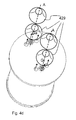
- FIGS. 4a-4b show various views of a first heat exchanger, which includes a condenser of the heat pump assembly, which can directly transfer the heat of the refrigerant to the second heat storage.
- Fig. 4a shows the first heat exchanger 422 in a oblique view obliquely from below, wherein the dashed lines describe the part of the heat storage housing 421, which is the housing 421 of the heat exchanger 422.
- Fig. 4b shows the first heat exchanger 422 in a oblique view obliquely from below, wherein the hole bottom 428 of the heat exchanger 422 has been omitted in the illustration.
- the housing of the heat exchanger is flanged to the heat accumulator.
- the heat exchanger 422 is embedded in the housing 421 so as to leave a space between the jacket 423 of the heat exchanger and the housing having a flow area of at least 100 cm 2 , so that the storage medium can flow downward between the shell 423 and the housing 421. Also, a corresponding distance between the housing bottom and the hole bottom 428 of the heat exchanger.
- the hole bottom has a family of concentrically arranged inner feed openings 425 and a family of concentrically arranged outer feed openings 426.
- the heat exchanger is divided into an inner area and an outer area, the two areas being defined by a cylinder wall (intermediate shell 427) concentric with the shell 423 of the Heat exchanger within the shell 427, are separated.
- the condenser conduit 431 coming from the heat pump is led through the housing bottom and the perforated bottom 428 into the inner region of the heat exchanger (ie within the intermediate jacket 427) and into an inner coil 435 guided helically upwards and then guided between shell 427 and jacket 423 in an outer winding 436 again helically down.
- the capacitor line 432 is passed through the hole bottom 428 from the heat exchanger and the housing bottom of the heat accumulator.
- the condenser line 435, 436 heats the storage medium (storage liquid) of the second heat accumulator, whereby the storage liquid within the heat exchanger flows upwards by convection.
- the cooler storage liquid flows through the gap between shell 423 of the heat exchanger and housing 421 down and through the openings 425, 426 of the bottom plate 428 in the heat exchanger and the capacitor lines over. This results in two essentially separate flows.
- an inner flow (inflow Fi, outflow Gi) through the inner feed openings 425 of the hole bottom 428 into the inner area within the intermediate shell 427 past the inner coil 435 of the capacitor line and an outer flow (inflow Fa, outflow Ga) through the outer feed openings 426 of the perforated bottom 428 in the inner region between the intermediate jacket 427 and jacket past the outer winding 435 of the capacitor line.
- the heat exchanger is closed at the top with a lid which has inner outlets for the inner area (for the inner outflow Gi) and outflow openings for the outer area of the heat exchanger (for the outer outflow Ga).
- the inner winding 435 has a higher temperature than the outer winding 436 during operation of the heat pump, which is why the inner outflow Gi from the inner region also has a higher temperature than the outer outflow Ga.
- a plurality eg 20 pieces, coaxial with a vertical axis A which is shown as a dashed line
- distributor bells 429 are mounted above the respective outflow openings. This makes it possible for the storage liquid, which leaves the respective outlet openings, to be layered according to their temperature in the corresponding layer of the heat accumulator; that is, the higher temperature storage liquid is accordingly layered closer to the head of the heat accumulator.
Landscapes
- Engineering & Computer Science (AREA)
- Physics & Mathematics (AREA)
- Thermal Sciences (AREA)
- Chemical & Material Sciences (AREA)
- Combustion & Propulsion (AREA)
- Mechanical Engineering (AREA)
- General Engineering & Computer Science (AREA)
- Life Sciences & Earth Sciences (AREA)
- Sustainable Development (AREA)
- Sustainable Energy (AREA)
- Heat-Pump Type And Storage Water Heaters (AREA)
Applications Claiming Priority (1)
| Application Number | Priority Date | Filing Date | Title |
|---|---|---|---|
| AT11322009 | 2009-07-20 |
Publications (1)
| Publication Number | Publication Date |
|---|---|
| EP2280227A2 true EP2280227A2 (fr) | 2011-02-02 |
Family
ID=43127352
Family Applications (1)
| Application Number | Title | Priority Date | Filing Date |
|---|---|---|---|
| EP10168518A Withdrawn EP2280227A2 (fr) | 2009-07-20 | 2010-07-06 | système pour stocker et récupérer la chaleur |
Country Status (2)
| Country | Link |
|---|---|
| EP (1) | EP2280227A2 (fr) |
| AT (1) | AT12877U1 (fr) |
Cited By (6)
| Publication number | Priority date | Publication date | Assignee | Title |
|---|---|---|---|---|
| AT512138A1 (de) * | 2011-05-27 | 2013-05-15 | Vaillant Group Austria Gmbh | Anlage zur Kraft-Wärmekopplung mit kombinierten Wärmespeichern |
| CN106642644A (zh) * | 2016-11-16 | 2017-05-10 | 上海贵鸣新能源科技有限公司 | 多能源恒温供水系统 |
| CN109611937A (zh) * | 2018-11-27 | 2019-04-12 | 中国建筑西北设计研究院有限公司 | 一种太阳能地源热泵及相变蓄热耦合供热系统和控制方法 |
| CN114322306A (zh) * | 2021-12-21 | 2022-04-12 | 江苏恒信诺金科技股份有限公司 | 洗浴废水源与地源组合制取生活热水的系统 |
| WO2022082231A1 (fr) * | 2020-10-12 | 2022-04-21 | Botha Johannes Matthys Beukes | Ensemble échangeur de chaleur |
| EP4674509A1 (fr) * | 2024-07-05 | 2026-01-07 | Siemens Aktiengesellschaft | Procédé et dispositif pour séparer le dioxyde de carbone d'un mélange gazeux |
Family Cites Families (5)
| Publication number | Priority date | Publication date | Assignee | Title |
|---|---|---|---|---|
| DE2619744C2 (de) * | 1976-05-05 | 1982-05-19 | Robert Bosch Gmbh, 7000 Stuttgart | Anlage zum Beheizen eines Gebäudes und zur Warmwasserbereitung |
| GB2026679B (en) * | 1978-07-24 | 1983-02-09 | Solar Holding Sa | Solar energy collector and system |
| EP0017975A1 (fr) * | 1979-04-17 | 1980-10-29 | Oliver Laing | Système de chauffage avec pompe à chaleur fonctionnant par courant de nuit |
| DE3025623A1 (de) * | 1980-07-05 | 1982-02-04 | Albert Speck Kg, 7531 Kieselbronn | Waermeabsorber |
| WO2009065182A1 (fr) * | 2007-11-23 | 2009-05-28 | Cool Or Cosy Energy Technology Pty Ltd | Accumulateur thermique |
-
2009
- 2009-07-20 AT ATGM8092/2010U patent/AT12877U1/de not_active IP Right Cessation
-
2010
- 2010-07-06 EP EP10168518A patent/EP2280227A2/fr not_active Withdrawn
Non-Patent Citations (1)
| Title |
|---|
| None |
Cited By (9)
| Publication number | Priority date | Publication date | Assignee | Title |
|---|---|---|---|---|
| AT512138A1 (de) * | 2011-05-27 | 2013-05-15 | Vaillant Group Austria Gmbh | Anlage zur Kraft-Wärmekopplung mit kombinierten Wärmespeichern |
| AT512138B1 (de) * | 2011-05-27 | 2014-02-15 | Vaillant Group Austria Gmbh | Anlage zur Kraft-Wärmekopplung mit kombinierten Wärmespeichern |
| CN106642644A (zh) * | 2016-11-16 | 2017-05-10 | 上海贵鸣新能源科技有限公司 | 多能源恒温供水系统 |
| CN106642644B (zh) * | 2016-11-16 | 2022-02-18 | 康贵明 | 多能源恒温供水系统 |
| CN109611937A (zh) * | 2018-11-27 | 2019-04-12 | 中国建筑西北设计研究院有限公司 | 一种太阳能地源热泵及相变蓄热耦合供热系统和控制方法 |
| WO2022082231A1 (fr) * | 2020-10-12 | 2022-04-21 | Botha Johannes Matthys Beukes | Ensemble échangeur de chaleur |
| CN114322306A (zh) * | 2021-12-21 | 2022-04-12 | 江苏恒信诺金科技股份有限公司 | 洗浴废水源与地源组合制取生活热水的系统 |
| EP4674509A1 (fr) * | 2024-07-05 | 2026-01-07 | Siemens Aktiengesellschaft | Procédé et dispositif pour séparer le dioxyde de carbone d'un mélange gazeux |
| WO2026008210A1 (fr) * | 2024-07-05 | 2026-01-08 | Siemens Aktiengesellschaft | Procédé de séparation de dioxyde de carbone d'un mélange gazeux et dispositif associé |
Also Published As
| Publication number | Publication date |
|---|---|
| AT12877U1 (de) | 2013-01-15 |
Similar Documents
| Publication | Publication Date | Title |
|---|---|---|
| EP2076721B1 (fr) | Pompe à chaleur à adsorption dotée d'un accumulateur de chaleur | |
| EP2280227A2 (fr) | système pour stocker et récupérer la chaleur | |
| DE2609489C3 (de) | Wärmepumpenanlage zum Aufheizen des Heizwassers und von Brauchwasser | |
| DE202011003668U1 (de) | Pufferspeicher zur Aufnahme von flüssigem Medium, Wasserversorgungsanlage mit einem derartigen Pufferspeicher sowie Pufferspeichervorrichtung mit zumindest einem Pufferspeicher | |
| EP0002839A1 (fr) | Procédé pour chauffer des locaux et application de ce procédé pour le chauffage d'un bâtiment | |
| DE102008060750B4 (de) | Allzweckwärmespeicher zur Speicherung verschiedener Arten von Energie | |
| EP0931986B1 (fr) | Installation solaire de chauffage et d'eau chaude pour bâtiments | |
| DE202011003667U1 (de) | Pufferspeicher zur Aufnahme von flüssigem Medium, Wasserversorgungsanlage mit einem derartigen Pufferspeicher sowie Pufferspeichervorrichtung mit zumindest einem Pufferspeicher | |
| DE202021004024U1 (de) | Hochtemperatur-Wärme-Speicher HT-S, Speicher-Verbund aus solchen Wärmespeichern sowie Heizung unter Verwendung solcher HT-S | |
| EP1058803B1 (fr) | Accumulateur de chaleur | |
| WO2013091892A2 (fr) | Système et procédé d'alimentation thermique | |
| DE2730406A1 (de) | Vorrichtungen und verfahren zur erhoehung der transportleistung von fernwaermenetzen | |
| WO2002012814A1 (fr) | Accumulateur de chaleur latente | |
| EP2815196B1 (fr) | Échangeur de chaleur pour une installation de chauffage ou un système de fourniture de chaleur | |
| DE102011005231A1 (de) | Pufferspeicher zur Aufnahme von flüssigem Medium, Wasserversorgungsanlage mit einem derartigen Pufferspeicher, Pufferspeichervorrichtung mit zumindest einem Pufferspeicher sowie Verfahren zum thermischen Aufbereiten von flüssigem Medium für eine Wasserversorgungsanlage für ein Gebäude | |
| AT523320B1 (fr) | ||
| EP4521036B1 (fr) | Système de réservoir bivalent multifonction | |
| DE2710139A1 (de) | Vorrichtung zum erhitzen von brauchwasser in einem fluessigkeitsgefuellten speicherkessel | |
| EP3054236A1 (fr) | Reservoir de fluide | |
| DE29816006U1 (de) | Haus- oder Raumheizungssystem mit Wärmespeicherung | |
| WO2003074941A1 (fr) | Echangeur thermique et dispositif de recuperation de l'energie thermique accumulee dans les eaux usees d'un batiment | |
| DE8206002U1 (de) | Vorrichtung zum erwaermen von brauchwasser unter ausnutzng der waerme eines fluids | |
| DE102022121914A1 (de) | Wärme- und Kältespeicher mit Gegenstromwärmetauscher | |
| DE102022129808A1 (de) | Warmwasserstation | |
| DE102004048884B4 (de) | Wärmeübertrager |
Legal Events
| Date | Code | Title | Description |
|---|---|---|---|
| PUAI | Public reference made under article 153(3) epc to a published international application that has entered the european phase |
Free format text: ORIGINAL CODE: 0009012 |
|
| AK | Designated contracting states |
Kind code of ref document: A2 Designated state(s): AL AT BE BG CH CY CZ DE DK EE ES FI FR GB GR HR HU IE IS IT LI LT LU LV MC MK MT NL NO PL PT RO SE SI SK SM TR |
|
| AX | Request for extension of the european patent |
Extension state: BA ME RS |
|
| STAA | Information on the status of an ep patent application or granted ep patent |
Free format text: STATUS: THE APPLICATION IS DEEMED TO BE WITHDRAWN |
|
| 18D | Application deemed to be withdrawn |
Effective date: 20150203 |