EP2280407A2 - Sputtervorrichtung mit Kathode mit drehbaren Targets und zugehörige Verfahren - Google Patents
Sputtervorrichtung mit Kathode mit drehbaren Targets und zugehörige Verfahren Download PDFInfo
- Publication number
- EP2280407A2 EP2280407A2 EP10170789A EP10170789A EP2280407A2 EP 2280407 A2 EP2280407 A2 EP 2280407A2 EP 10170789 A EP10170789 A EP 10170789A EP 10170789 A EP10170789 A EP 10170789A EP 2280407 A2 EP2280407 A2 EP 2280407A2
- Authority
- EP
- European Patent Office
- Prior art keywords
- sputtering
- target
- targets
- vacuum chamber
- yoke
- Prior art date
- Legal status (The legal status is an assumption and is not a legal conclusion. Google has not performed a legal analysis and makes no representation as to the accuracy of the status listed.)
- Granted
Links
Images


Classifications
-
- H—ELECTRICITY
- H01—ELECTRIC ELEMENTS
- H01J—ELECTRIC DISCHARGE TUBES OR DISCHARGE LAMPS
- H01J37/00—Discharge tubes with provision for introducing objects or material to be exposed to the discharge, e.g. for the purpose of examination or processing thereof
- H01J37/32—Gas-filled discharge tubes
- H01J37/34—Gas-filled discharge tubes operating with cathodic sputtering
- H01J37/3411—Constructional aspects of the reactor
- H01J37/3414—Targets
- H01J37/342—Hollow targets
-
- C—CHEMISTRY; METALLURGY
- C23—COATING METALLIC MATERIAL; COATING MATERIAL WITH METALLIC MATERIAL; CHEMICAL SURFACE TREATMENT; DIFFUSION TREATMENT OF METALLIC MATERIAL; COATING BY VACUUM EVAPORATION, BY SPUTTERING, BY ION IMPLANTATION OR BY CHEMICAL VAPOUR DEPOSITION, IN GENERAL; INHIBITING CORROSION OF METALLIC MATERIAL OR INCRUSTATION IN GENERAL
- C23C—COATING METALLIC MATERIAL; COATING MATERIAL WITH METALLIC MATERIAL; SURFACE TREATMENT OF METALLIC MATERIAL BY DIFFUSION INTO THE SURFACE, BY CHEMICAL CONVERSION OR SUBSTITUTION; COATING BY VACUUM EVAPORATION, BY SPUTTERING, BY ION IMPLANTATION OR BY CHEMICAL VAPOUR DEPOSITION, IN GENERAL
- C23C14/00—Coating by vacuum evaporation, by sputtering or by ion implantation of the coating forming material
- C23C14/22—Coating by vacuum evaporation, by sputtering or by ion implantation of the coating forming material characterised by the process of coating
- C23C14/34—Sputtering
- C23C14/3407—Cathode assembly for sputtering apparatus, e.g. Target
-
- C—CHEMISTRY; METALLURGY
- C23—COATING METALLIC MATERIAL; COATING MATERIAL WITH METALLIC MATERIAL; CHEMICAL SURFACE TREATMENT; DIFFUSION TREATMENT OF METALLIC MATERIAL; COATING BY VACUUM EVAPORATION, BY SPUTTERING, BY ION IMPLANTATION OR BY CHEMICAL VAPOUR DEPOSITION, IN GENERAL; INHIBITING CORROSION OF METALLIC MATERIAL OR INCRUSTATION IN GENERAL
- C23C—COATING METALLIC MATERIAL; COATING MATERIAL WITH METALLIC MATERIAL; SURFACE TREATMENT OF METALLIC MATERIAL BY DIFFUSION INTO THE SURFACE, BY CHEMICAL CONVERSION OR SUBSTITUTION; COATING BY VACUUM EVAPORATION, BY SPUTTERING, BY ION IMPLANTATION OR BY CHEMICAL VAPOUR DEPOSITION, IN GENERAL
- C23C14/00—Coating by vacuum evaporation, by sputtering or by ion implantation of the coating forming material
- C23C14/22—Coating by vacuum evaporation, by sputtering or by ion implantation of the coating forming material characterised by the process of coating
- C23C14/34—Sputtering
- C23C14/3435—Applying energy to the substrate during sputtering
- C23C14/3442—Applying energy to the substrate during sputtering using an ion beam
-
- C—CHEMISTRY; METALLURGY
- C23—COATING METALLIC MATERIAL; COATING MATERIAL WITH METALLIC MATERIAL; CHEMICAL SURFACE TREATMENT; DIFFUSION TREATMENT OF METALLIC MATERIAL; COATING BY VACUUM EVAPORATION, BY SPUTTERING, BY ION IMPLANTATION OR BY CHEMICAL VAPOUR DEPOSITION, IN GENERAL; INHIBITING CORROSION OF METALLIC MATERIAL OR INCRUSTATION IN GENERAL
- C23C—COATING METALLIC MATERIAL; COATING MATERIAL WITH METALLIC MATERIAL; SURFACE TREATMENT OF METALLIC MATERIAL BY DIFFUSION INTO THE SURFACE, BY CHEMICAL CONVERSION OR SUBSTITUTION; COATING BY VACUUM EVAPORATION, BY SPUTTERING, BY ION IMPLANTATION OR BY CHEMICAL VAPOUR DEPOSITION, IN GENERAL
- C23C14/00—Coating by vacuum evaporation, by sputtering or by ion implantation of the coating forming material
- C23C14/22—Coating by vacuum evaporation, by sputtering or by ion implantation of the coating forming material characterised by the process of coating
- C23C14/34—Sputtering
- C23C14/3464—Sputtering using more than one target
-
- C—CHEMISTRY; METALLURGY
- C23—COATING METALLIC MATERIAL; COATING MATERIAL WITH METALLIC MATERIAL; CHEMICAL SURFACE TREATMENT; DIFFUSION TREATMENT OF METALLIC MATERIAL; COATING BY VACUUM EVAPORATION, BY SPUTTERING, BY ION IMPLANTATION OR BY CHEMICAL VAPOUR DEPOSITION, IN GENERAL; INHIBITING CORROSION OF METALLIC MATERIAL OR INCRUSTATION IN GENERAL
- C23C—COATING METALLIC MATERIAL; COATING MATERIAL WITH METALLIC MATERIAL; SURFACE TREATMENT OF METALLIC MATERIAL BY DIFFUSION INTO THE SURFACE, BY CHEMICAL CONVERSION OR SUBSTITUTION; COATING BY VACUUM EVAPORATION, BY SPUTTERING, BY ION IMPLANTATION OR BY CHEMICAL VAPOUR DEPOSITION, IN GENERAL
- C23C14/00—Coating by vacuum evaporation, by sputtering or by ion implantation of the coating forming material
- C23C14/22—Coating by vacuum evaporation, by sputtering or by ion implantation of the coating forming material characterised by the process of coating
- C23C14/34—Sputtering
- C23C14/35—Sputtering by application of a magnetic field, e.g. magnetron sputtering
- C23C14/352—Sputtering by application of a magnetic field, e.g. magnetron sputtering using more than one target
-
- H—ELECTRICITY
- H01—ELECTRIC ELEMENTS
- H01J—ELECTRIC DISCHARGE TUBES OR DISCHARGE LAMPS
- H01J37/00—Discharge tubes with provision for introducing objects or material to be exposed to the discharge, e.g. for the purpose of examination or processing thereof
- H01J37/32—Gas-filled discharge tubes
- H01J37/34—Gas-filled discharge tubes operating with cathodic sputtering
- H01J37/3411—Constructional aspects of the reactor
- H01J37/3414—Targets
- H01J37/3417—Arrangements
-
- H—ELECTRICITY
- H01—ELECTRIC ELEMENTS
- H01J—ELECTRIC DISCHARGE TUBES OR DISCHARGE LAMPS
- H01J37/00—Discharge tubes with provision for introducing objects or material to be exposed to the discharge, e.g. for the purpose of examination or processing thereof
- H01J37/32—Gas-filled discharge tubes
- H01J37/34—Gas-filled discharge tubes operating with cathodic sputtering
- H01J37/3411—Constructional aspects of the reactor
- H01J37/3414—Targets
- H01J37/3426—Material
- H01J37/3429—Plural materials
-
- H—ELECTRICITY
- H01—ELECTRIC ELEMENTS
- H01J—ELECTRIC DISCHARGE TUBES OR DISCHARGE LAMPS
- H01J37/00—Discharge tubes with provision for introducing objects or material to be exposed to the discharge, e.g. for the purpose of examination or processing thereof
- H01J37/32—Gas-filled discharge tubes
- H01J37/34—Gas-filled discharge tubes operating with cathodic sputtering
- H01J37/3411—Constructional aspects of the reactor
- H01J37/3414—Targets
- H01J37/3432—Target-material dispenser
-
- H—ELECTRICITY
- H01—ELECTRIC ELEMENTS
- H01J—ELECTRIC DISCHARGE TUBES OR DISCHARGE LAMPS
- H01J37/00—Discharge tubes with provision for introducing objects or material to be exposed to the discharge, e.g. for the purpose of examination or processing thereof
- H01J37/32—Gas-filled discharge tubes
- H01J37/34—Gas-filled discharge tubes operating with cathodic sputtering
- H01J37/3411—Constructional aspects of the reactor
- H01J37/3435—Target holders (includes backing plates and endblocks)
Definitions
- Certain example embodiments of this invention relate to sputtering apparatuses, More particularly, certain example embodiments of this invention relate to sputtering apparatuses that include cathodes having rotatable targets.
- a sputtering apparatus includes a plurality of targets such that a first one or ones of target(s) may be used for sputtering in a first mode, while a second one or ones of target(s) may be used for sputtering in a second mode.
- the sputtering apparatus may switch between modes by rotating the position of the targets, e.g., such that one or more target(s) to be used protrude into the main chamber of the apparatus, while one or more target(s) to be unused are recessed into a body portion of a cathode of (e.g., integrally formed with) the sputtering apparatus.
- sputter coating is a thin film coating process that involves the transport of almost any material from a target to a substrate of almost any other material.
- the ejection of the target material is accomplished by bombarding the surface of the target with gas ions accelerated by a high voltage. Particles are ejected from the target as a result of momentum transfer between the accelerated gas ions and the target. Upon ejection, the target particles traverse the sputtering chamber and are subsequently deposited on a substrate as a thin film.
- Sputtering processes typically utilize an enclosed chamber confining a sputtering gas, a target electrically connected to a cathode, a substrate, and a chamber which itself may serve as the electrical anode.
- a power supply typically is connected such that the negative terminal of the power supply is connected to the cathode and the positive terminal is connected to the chamber walls.
- a sputtering gas plasma is formed and maintained within the chamber near the surface of the sputtering target.
- the positively charged ions are accelerated toward the target material by the electrical potential between the sputtering gas plasma and the target and bombard the surface of the target material. As ions bombard the target, molecules of target material are ejected from the target surface and coat the substrate.
- One known technique for enhancing conventional sputtering processes involves arranging magnets behind or near the target to influence the path taken by electrons within the sputtering chamber, thereby increasing the frequency of collisions with sputtering gas atoms or molecules. Additional collisions create additional ions, thus further sustaining the sputtering gas plasma.
- An apparatus utilizing this enhanced form of sputtering by means of strategically located magnets generally is referred to as a magnetron system.
- Conventional sputtering apparatuses work well when depositing one or two thin film layers, as some single-chamber designs are configured to deposit the same same.
- conventional sputtering techniques suffer from several disadvantages.
- layer stacks become more complex, e.g., at least in requiring multiple layers in a single layer stack, conventional sputtering apparatuses encounter difficulties. For example, one must typically determine how best to use one's existing equipment in depositing more complicated layer stacks, or at least layer stacks with more layers.
- Another possible solution to such difficulties involves temporarily halting the assembly line, removing a target in a sputtering chamber, and restarting the assembly line.
- this solution may require the sputtering chamber to be vented (e.g., in the event that an inert gas is being used in connection therewith), cooled (e.g., as sputtering typically takes place at several hundred degrees Celsius), pressurized (e.g., as sputtering typically is performed in an at least partial vacuum), etc. Because these wait times are imposed, yield is reduced, as people and intermediate products are simply "waiting around" during these configuration and reconfiguration processes. Production speeds may be significantly decreased because of the waiting involved in such processes.
- a sputtering apparatus for sputter coating an article in a reactive environment.
- the sputtering apparatus includes a vacuum chamber.
- a cathode has a hollow body portion.
- a substantially planar yoke is provided between the cathode and chamber, with the yoke including at least first and second target locations provided on a first major surface thereof, and at least third and fourth target locations provided on a second major surface thereof.
- the at least first and second target locations at least initially face the vacuum chamber, and the at least third and fourth target locations at least initially face the cathode.
- the yoke is rotatable such that, upon a rotation, the at least third and fourth target locations face the vacuum chamber and the at least first and second target locations face the cathode. Upon a further rotation, the at least first and second target locations face the vacuum chamber, and the at least third and fourth target locations face the cathode.
- a sputtering apparatus for sputter coating an article in a reactive environment. At least one power source is provided. A vacuum chamber is provided. A cathode has a hollow body portion. A yoke is provided between the cathode and chamber, with the yoke including at least one target location provided on each major surface thereof. A plurality of sputtering targets is provided, with each sputtering target being provided to one of the target locations. Each sputtering target provided on the major surface of the yoke closest the vacuum chamber protrudes into the vacuum chamber, while any other sputtering target(s) is/are recessed in the body portion of the cathode.
- the yoke is rotatable about an axis such that a rotation thereof causes at least one different sputtering target to protrude into the vacuum chamber. Only the sputtering target(s) protruding into the vacuum chamber receive power from the at least on power source.
- a method of sputter coating a plurality of articles comprising: at least one power source; a vacuum chamber; a cathode having a hollow body portion; and a yoke provided between the cathode and chamber, the yoke including at least one target location provided on each major surface thereof; and a plurality of sputtering targets, each said sputtering target being provided to one said target location.
- Each sputtering target provided on the major surface of the yoke closest the vacuum chamber protrudes into the vacuum chamber, while any other sputtering target(s) is/are recessed in the body portion of the cathode.
- the yoke is rotatable about an axis such that a rotation thereof causes at least one different sputtering target to protrude into the vacuum chamber. Only the sputtering target(s) protruding into the vacuum chamber receive power from the at least on power source. At least one said target location is configured to accommodate an ion beam source in place of a sputtering target.
- a first article is provided to the sputtering apparatus.
- a first thin film is sputter deposited, directly or indirectly, on the first article.
- the yoke is rotated.
- a second article is provided to the sputtering apparatus.
- a second thin film is sputter deposited, directly or indirectly, on the first article, with the second thin film being different
- a sputtering apparatus for sputter coating an article in a reactive environment.
- the sputtering apparatus comprises at least one power source, a vacuum chamber; and a cathode having a hollow body portion.
- a plurality of yokes are provided between the cathode and chamber, with each said yoke including at least one target location provided on each major surface thereof.
- a plurality of sputtering targets are provided, with each said sputtering target being provided to one said target location.
- Each sputtering target provided on the major surfaces of the yokes closest the vacuum chamber protrudes into the vacuum chamber, while any other sputtering target(s) is/are recessed in the body portion of the cathode.
- the yokes are rotatable about an axis such that a rotation thereof causes at least one different sputtering target to protrude into the vacuum chamber. Only the sputtering target(s) protruding into the vacuum chamber receive power from the at least on power source.
- the yokes may be individually rotatable.
- Figure 1 is a simplified schematic illustration of a conventional reactive DC magnetron sputtering apparatus and target
- Figure 2 is a top plan view of a conventional, planar sputtering target
- Figure 3 is a cross section of the sputtering target of Fig. 2 ;
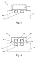
- Figure 4 is a cross section of a dual cylindrical magnetic (dual C-MAG) sputtering apparatus
- Figure 5 is a cross section of an improved sputtering apparatus having a revolver cathode and four cylindrical magnetic targets in accordance with certain example embodiments;
- Figures 6a-6c illustrate targets being rotated within the revolver cathode of Fig. 5 in accordance with certain example embodiments
- Figure 7 is a cross section of an improved sputtering apparatus having a revolver cathode and four planar targets in accordance with certain example embodiments.
- Figure 8 is a cross section of an improved sputtering apparatus having a revolver cathode and two planar targets and two cylindrical magnetic targets in accordance with certain example embodiments.
- Certain example embodiments relate to sputtering apparatuses that include a plurality of targets such that a first one or ones of target(s) may be used for sputtering in a first mode, while a second one or ones of target(s) may be used for sputtering in a second mode. Modes may be switched in certain example embodiments by rotating the position of the targets, e.g., such that one or more target(s) to be used protrude into the main chamber of the apparatus, while one or more target(s) to be unused are recessed into a body portion of a cathode of (e.g., integrally formed with) the sputtering apparatus.
- a cathode of e.g., integrally formed with
- Fig. 1 is a simplified schematic illustration of a conventional reactive DC magnetron sputtering apparatus and target.
- Apparatus 10 typically includes a sputtering chamber 16, a vacuum means 22 to evacuate the chamber, a sputtering target such as a planar target 40 (as illustrated in Figs. 2-3 , for example), one or more magnets 15, a supply of sputtering gas 24, a power supply 20 having a positive terminal and a negative terminal, and means 14 to support and/or transport the substrate in the deposition region of the chamber.
- the target typically is electrically connected to cathode 12.
- Cathode 12 typically is electrically connected to the negative terminal of power supply 20.
- the sputtering chamber 16 itself sometimes is the electrical anode.
- a separate anode element may be included inside the sputtering chamber and may be connected to its own power supply so as to be at some set potential other than ground with respect to cathode 12.
- the sputtering chamber 16 is at ground potential and, in some example instances, the sputtering chamber 16 may be connected to the positive terminal of the power supply.
- the target is at the most negative potential of any of the components of the sputtering apparatus (besides the negative terminal of the power supply). It will be appreciated that various electrical connections may be made between the power supply 20 and the various components of the sputtering apparatus 10.
- a sputtering gas 24 is introduced into chamber 16.
- the sputtering gas 24 may be an inert gas such as argon, neon, etc.
- Other forms of sputtering processes known as reactive sputtering may use reactive non-inert gases such as oxygen or nitrogen.
- some sputtering operations may utilize a mixture of one or more inert gases and/or non-inert gases.
- the sputtering target provides the material which is to be deposited onto the substrate.
- the size, shape, and construction of the target may vary depending upon the material and the size and shape of the substrate.
- a typical planar sputtering target 40 before sputtering is shown in Figs. 2-3 .
- the planar sputtering target 40 comprises an electrically conducting backing plate 41 and a layer of electrically conducting target material 42 deposited thereon.
- An electrical insulator 17 may be employed to cover any exposed region of backing member 41 or other underlying surface. Typically, the chamber walls 16 will abut insulator 17 and extend up to, but not contact, the target material 42.
- Backing member 41 is not necessary for all target materials (e.g., such as those that are inherently rigid or of sufficient thickness). Thus, in such instances, the target material itself may also serve as the backing member.
- Fig. 4 is a cross section of a dual cylindrical magnetic (also sometimes called a dual C-MAG) sputtering apparatus 10'.
- the dual C-MAG sputtering apparatus 10' includes first and second rotatable magnet targets 40a and 40b.
- the first and second targets 40a and 40b hang into the chamber 16 from the cathode assembly 12',
- a flux of material emanates from each of the two rotating magnetic from the first and second rotating targets 40a and 40b down through the chamber 16 and onto a substrate (not shown) passing therethrough.
- One mixed layer, two separate layers, etc. may be deposited on a substrate using this arrangement.
- Certain example embodiments relate to sputtering apparatuses that include a plurality of targets such that a first one or ones of target(s) may be used for sputtering in a first mode, while a second one or ones of target(s) may be used for sputtering in a second mode. Modes may be switched in certain example embodiments by rotating the position of the targets, e.g., such that one or more target(s) to be used protrude into the main chamber of the apparatus, while one or more target(s) to be unused are recessed into a body portion of a cathode of (e.g., integrally formed with) the sputtering apparatus.
- a cathode of e.g., integrally formed with
- the cathode assemblies of certain example embodiments are sometimes referred to herein as "revolver cathodes.”
- the ability to rotate targets to active and inactive positions within the sputtering apparatus enables a number of example advantages to be realized. For instance, in certain example embodiments, the type of target material in a chamber may be changed without venting the chamber, different types of targets may be used within a single apparatus, etc.
- Fig. 5 is a cross section of an improved sputtering apparatus 50 having a revolver cathode 52 and four cylindrical magnetic targets in accordance with certain example embodiments.
- the improved sputtering apparatus 50 of Fig. 5 is similar to the sputtering apparatus 10' of Fig: 4 in that, in both first, two cylindrical magnetic targets protrude into the sputtering chamber from a cathode assembly.
- the improved sputtering apparatus 50 of Fig. 5 includes a revolver cathode 52 and four cylindrical magnetic targets 56a-d.
- two cylindrical targets in active positions 56a and 56b protrude into the sputtering chamber 16
- two additional cylindrical targets in inactive positions 56c and 56d are recessed in the revolver cathode 52.
- the cathode 12' thereof has a bottom surface adjacent to the top surface of the sputtering chamber 16 which essentially separates the interior of the cathode 12' from the interior of the sputtering chamber 16.
- the revolver cathode 52 in Fig. 5 does not have a bottom surface that separates the interior of the revolver cathode 52 from the interior of the sputtering chamber 16.
- a target revolver yoke 54 is provided in place of this bottom surface.
- This target revolver yoke 54 holds all of the targets, e.g., first and second cylindrical targets in active positions 56a and 56b and third and fourth cylindrical targets in inactive positions 56c and 56d.
- the target revolver yoke 54 may not fully (or even substantially fully) isolate the interior of the revolver cathode 52 from the interior of the chamber 16. That is, in certain example embodiments, there may be a gap between one or more edge(s) of the yoke 54 and the side walls of the revolver cathode 54. However, in certain example embodiments, the target revolver yoke 54 may fully or substantially fully isolate the interior of the revolver cathode 52 from the interior of the chamber 16, essentially taking the place of the bottom surface of the cathode 12' in Fig. 4 .
- the materials in the active targets and inactive targets may be the same or different from one another. That is, the active targets may be of a first material and the inactive targets may be of a second material, one active target may be the same as one inactive target, etc. Any target material may be used for any of the four locations, depending on the desired coating or application.
- the targets may be moved from active-to-inactive and inactive-to-active positions when the yoke is rotated, e.g., about an axis 54a in the approximate center thereof.
- Figs. 6a-6c illustrate targets being rotated within the revolver cathode of Fig. 5 in accordance with certain example embodiments.
- Fig. 6a shows the targets being configured for a first mode of use.
- first and second targets 62a and 62b are provided at first and second active positions 56a and 56b
- third and fourth targets 62c and 62d are provided at first and second inactive positions 56c and 56d. Production may be started in this first mode.
- Cooling fluid e.g., water
- Cooling fluid may flow into all target tubes, both in the active and inactive positions, e.g., to reduce the likelihood of the damage or corruption to any of the target material.
- in power is provided only to those target tubes in the active positions 56a and 56b.
- the sputtering process may be temporarily suspended.
- the yoke 54 may be rotated, e.g., about its axis 54a.
- Fig. 6b shows the locations of the target tubes after a 90 degree clockwise rotation
- Fig. 6c shows the locations of the target tubes after another 90 degree clockwise rotation (for a total 180 degree rotation).
- the previously unused targets 62c and 62d are now located in active positions 56a and 56b, while the previously used targets 62a and 62b are now in inactive positions 56c and 56d.
- Power is now provided to the targets 62c and 62d that are located in the active positions 56a and 56b, all four targets receiving cooling fluids, and sputtering may be restarted in the second mode.
- the rotation may be performed manually and/or by machine in example embodiments of this invention. Rotation may be in the counterclockwise direction in certain example embodiments.
- power may be supplied to the targets by means of respective connectors located on the cathode and on the targets that are configured to engage with one another when in the active position. Upon partial rotation, the connectors may lose contact, thus disconnecting the targets from the power source. Alternatively, or in addition, in certain example embodiments, all tubes may be switched, such that only those tubes in the active locations are "turned on.”
- one or more external hatches may be provided so that the targets in the inactive positions may be removed, inspected, replaced, etc.
- the yoke 54 may be made of a 300 series stainless steel.
- the magnetic permeability (as measured by relative permeability or ⁇ r) of 300 series stainless steel ranges from about 1.00-8.48, with an average magnetic permeability of about 1.27, as derived from 181 of the different grades of 300 series stainless steel. Accordingly, because 300 series stainless steel has low or substantially no magnetic permeability, it has little interference with the magnetic field generated during sputtering.
- 304 series stainless steel may be used.
- each target location may have a cylindrical magnetic target, a planar target, or an ion beam. Ion beam milling has been described independently and in connection with sputtering apparatuses, for example, in U.S. Patent Nos.
- the size of the opening may be adjusted so as to accommodate planar targets (including the rotation thereof), as planar targets tend to be larger than cylindrical targets in a widthwise direction.
- Fig. 7 is a cross section of an improved sputtering apparatus 70 having a revolver cathode and four planar targets 72a-d in accordance with certain example embodiments.
- first and second planar targets 72a and 72b are provided in active locations 56a and 56b
- third and fourth planar targets 72c and 72d are provided in inactive locations 56c and 56d. These targets may be rotated as described above.
- Fig. 8 is a cross section of an improved sputtering apparatus 80 having a revolver cathode and two planar targets 72a and 72b and two cylindrical magnetic targets 62a and 62b in accordance with certain example embodiments.
- the first and second planar targets 72a and 72b are provided in inactive locations 56c and 56d, while the first and second cylindrical magnetic targets 62a and 62b are provided in the active locations 62a and 62b.
- the targets may be rotated as described above, such that the first and second planar targets 72a and 72b moved to the active locations and the first and second cylindrical magnetic targets 62a and 62b are moved to the inactive locations.
- a yoke may in certain example embodiments support one active location on a first side and one inactive location on a second side, one location on the first side and two locations on the second side, etc.
- a substantially planar yoke other yoke shapes also are possible.
- a substantially triangular yoke may be provided so as to accommodate targets and/or ion beams on each of the three sides, with each side being differently or similarly configurable.
- the amount of rotation needed to changing from an inactive to active position may change according to the shape of the yoke. For example, for a triangle, a 60 degree rotation may be used to change from a first inactive position to the active position, and a 120 degree rotation may be used to change from a second inactive position to the active position.
- multiple targets may be provided to one or more sides of a single yoke. This may be used to provide, for example, ion beam assisted dual planar cathode arrangements.
- multiple yokes also may be provided.
- the yokes may be rotatable substantially independent of one another.
- a first yoke may be provided to select a first planar target
- a second yoke may be provided to select a second planar target
- a third yoke may be provided to select an ion beam.
- a target location on a yoke may be left empty, e.g., so that the location essentially can be turned off.
- some targets or other devices may be provided at a fixed position remote from the yoke.
- the ion beam may be in a fixed location remote from the yoke.
- the improved sputtering apparatuses of certain example embodiments may enable the coater target configuration to be easily changed.
- the types of targets, target materials, etc. may be changed by simple rotation of a yoke.
- the selective reconfiguration techniques may enable the sputtering apparatus to switch between single silver to double or triple silver based antireflective coatings.
- the chamber may be held at a pressure less than atmospheric and/or at an elevated temperature during such configuration changes.
- the time savings may increase the production yields of coaters.
- the coater may generally operate at a pressure of about 10-3 mbars, and the atmospheric pressure generally may be about 1030 mbars.
- a particular layer or coating may be said to be “on” or “supported by” a surface or another coating (directly or indirectly), other layer(s) and/or coatings may be provided therebetween.
- a coating may be considered “on” and “supported by” a surface even if other layer(s) are provided between layer(s) and the substrate.
- certain layers or coatings may be removed in certain embodiments, while others may be added in other embodiments of this invention without departing from the overall spirit of certain embodiments of this invention.
- an encapsulating coating applied in liquid sol-gel form in accordance with an example embodiment may be said to be "on” or “supported by” a sputtering target material, even though other coatings and/or layers may be provided between the sol-gel formed coating and the target material.
Landscapes
- Chemical & Material Sciences (AREA)
- Engineering & Computer Science (AREA)
- Physics & Mathematics (AREA)
- Plasma & Fusion (AREA)
- Analytical Chemistry (AREA)
- Chemical Kinetics & Catalysis (AREA)
- Materials Engineering (AREA)
- Mechanical Engineering (AREA)
- Metallurgy (AREA)
- Organic Chemistry (AREA)
- Physical Vapour Deposition (AREA)
Priority Applications (1)
| Application Number | Priority Date | Filing Date | Title |
|---|---|---|---|
| PL10170789T PL2280407T3 (pl) | 2009-07-31 | 2010-07-26 | Urządzenie napylające posiadające katodę z obrotowymi źródłami i powiązana z nim metoda |
Applications Claiming Priority (1)
| Application Number | Priority Date | Filing Date | Title |
|---|---|---|---|
| US12/461,130 US10586689B2 (en) | 2009-07-31 | 2009-07-31 | Sputtering apparatus including cathode with rotatable targets, and related methods |
Publications (3)
| Publication Number | Publication Date |
|---|---|
| EP2280407A2 true EP2280407A2 (de) | 2011-02-02 |
| EP2280407A3 EP2280407A3 (de) | 2014-04-30 |
| EP2280407B1 EP2280407B1 (de) | 2018-11-07 |
Family
ID=43242628
Family Applications (1)
| Application Number | Title | Priority Date | Filing Date |
|---|---|---|---|
| EP10170789.1A Active EP2280407B1 (de) | 2009-07-31 | 2010-07-26 | Sputtervorrichtung mit Kathode mit drehbaren Targets und zugehöriges Verfahren |
Country Status (5)
| Country | Link |
|---|---|
| US (2) | US10586689B2 (de) |
| EP (1) | EP2280407B1 (de) |
| ES (1) | ES2707557T3 (de) |
| PL (1) | PL2280407T3 (de) |
| TR (1) | TR201901436T4 (de) |
Cited By (1)
| Publication number | Priority date | Publication date | Assignee | Title |
|---|---|---|---|---|
| KR20190091514A (ko) * | 2016-12-14 | 2019-08-06 | 슈나이더 게엠베하 운트 코. 카게 | 안경 렌즈를 코팅하기 위한 설비, 방법 및 캐리어 |
Families Citing this family (10)
| Publication number | Priority date | Publication date | Assignee | Title |
|---|---|---|---|---|
| US10586689B2 (en) * | 2009-07-31 | 2020-03-10 | Guardian Europe S.A.R.L. | Sputtering apparatus including cathode with rotatable targets, and related methods |
| CN101988189B (zh) * | 2009-08-07 | 2012-10-10 | 鸿富锦精密工业(深圳)有限公司 | 磁控溅射靶及采用该磁控溅射靶的磁控溅射装置 |
| WO2012140798A1 (ja) * | 2011-04-12 | 2012-10-18 | 株式会社アルバック | ターゲット及びターゲットの製造方法 |
| JP5882934B2 (ja) * | 2012-05-09 | 2016-03-09 | シーゲイト テクノロジー エルエルシー | スパッタリング装置 |
| US9809876B2 (en) * | 2014-01-13 | 2017-11-07 | Centre Luxembourgeois De Recherches Pour Le Verre Et La Ceramique (C.R.V.C.) Sarl | Endblock for rotatable target with electrical connection between collector and rotor at pressure less than atmospheric pressure |
| KR102469559B1 (ko) * | 2016-10-14 | 2022-11-22 | 에바텍 아크티엔게젤샤프트 | 스퍼터링 소스 |
| JP2019189913A (ja) * | 2018-04-26 | 2019-10-31 | 京浜ラムテック株式会社 | スパッタリングカソード、スパッタリングカソード集合体およびスパッタリング装置 |
| GB2588937B (en) * | 2019-11-15 | 2023-01-04 | Dyson Technology Ltd | Sputter deposition |
| KR20230084282A (ko) * | 2020-10-14 | 2023-06-12 | 어플라이드 머티어리얼스, 인코포레이티드 | 스퍼터 증착 소스, 증착 장치, 및 기판을 코팅하는 방법 |
| CN116288198B (zh) * | 2023-02-03 | 2025-04-15 | 常熟市虞华真空设备科技有限公司 | 一种磁控溅射真空镀膜机 |
Citations (19)
| Publication number | Priority date | Publication date | Assignee | Title |
|---|---|---|---|---|
| US5262032A (en) | 1991-05-28 | 1993-11-16 | Leybold Aktiengesellschaft | Sputtering apparatus with rotating target and target cooling |
| US5284564A (en) | 1991-07-30 | 1994-02-08 | Leybold Aktiengesellschaft | Magnetron sputtering cathode for vacuum coating apparatus |
| US5317006A (en) | 1989-06-15 | 1994-05-31 | Microelectronics And Computer Technology Corporation | Cylindrical magnetron sputtering system |
| US5403458A (en) | 1993-08-05 | 1995-04-04 | Guardian Industries Corp. | Sputter-coating target and method of use |
| US5527439A (en) | 1995-01-23 | 1996-06-18 | The Boc Group, Inc. | Cylindrical magnetron shield structure |
| US5591314A (en) | 1995-10-27 | 1997-01-07 | Morgan; Steven V. | Apparatus for affixing a rotating cylindrical magnetron target to a spindle |
| US5922176A (en) | 1992-06-12 | 1999-07-13 | Donnelly Corporation | Spark eliminating sputtering target and method for using and making same |
| US6368664B1 (en) | 1999-05-03 | 2002-04-09 | Guardian Industries Corp. | Method of ion beam milling substrate prior to depositing diamond like carbon layer thereon |
| US20040020761A1 (en) | 2002-05-06 | 2004-02-05 | Guardian Industries Corp. | Sputter coating apparatus including ion beam source(s), and corresponding method |
| US6740211B2 (en) | 2001-12-18 | 2004-05-25 | Guardian Industries Corp. | Method of manufacturing windshield using ion beam milling of glass substrate(s) |
| US6808606B2 (en) | 1999-05-03 | 2004-10-26 | Guardian Industries Corp. | Method of manufacturing window using ion beam milling of glass substrate(s) |
| US20060008657A1 (en) | 2004-06-25 | 2006-01-12 | C.R.V.C., Grand Duche De Luxembourg | Method of forming coated article using sputtering target(s) and ion source(s) and corresponding apparatus |
| US7183559B2 (en) | 2004-11-12 | 2007-02-27 | Guardian Industries Corp. | Ion source with substantially planar design |
| US7229533B2 (en) | 2004-06-25 | 2007-06-12 | Guardian Industries Corp. | Method of making coated article having low-E coating with ion beam treated and/or formed IR reflecting layer |
| US7311975B2 (en) | 2004-06-25 | 2007-12-25 | Centre Luxembourgeois De Recherches Pour Le Verre Et La Ceramique S.A. (C.R.V.C.) | Coated article having low-E coating with ion beam treated IR reflecting layer and corresponding method |
| US20080017112A1 (en) | 2006-07-18 | 2008-01-24 | Guardian Industries Corp. | Ion source with recess in electrode |
| US7405411B2 (en) | 2005-05-06 | 2008-07-29 | Guardian Industries Corp. | Ion source with multi-piece outer cathode |
| US7488951B2 (en) | 2006-08-24 | 2009-02-10 | Guardian Industries Corp. | Ion source including magnet and magnet yoke assembly |
| US7550067B2 (en) | 2004-06-25 | 2009-06-23 | Guardian Industries Corp. | Coated article with ion treated underlayer and corresponding method |
Family Cites Families (36)
| Publication number | Priority date | Publication date | Assignee | Title |
|---|---|---|---|---|
| LU52106A1 (de) * | 1966-10-05 | 1968-05-07 | ||
| US3756939A (en) * | 1971-10-14 | 1973-09-04 | Materials Research Corp | Target mounting device for sequential sputtering |
| US5270517A (en) | 1986-12-29 | 1993-12-14 | Ppg Industries, Inc. | Method for fabricating an electrically heatable coated transparency |
| US4806220A (en) | 1986-12-29 | 1989-02-21 | Ppg Industries, Inc. | Method of making low emissivity film for high temperature processing |
| US4898789A (en) | 1988-04-04 | 1990-02-06 | Ppg Industries, Inc. | Low emissivity film for automotive heat load reduction |
| GB8900166D0 (en) | 1989-01-05 | 1989-03-01 | Glaverbel | Glass coating |
| US5178980A (en) | 1991-09-03 | 1993-01-12 | Xerox Corporation | Photoconductive imaging members with a fullerene compound |
| JPH05171432A (ja) | 1991-12-26 | 1993-07-09 | Fujitsu Ltd | スパッタ装置 |
| US5302449A (en) | 1992-03-27 | 1994-04-12 | Cardinal Ig Company | High transmittance, low emissivity coatings for substrates |
| US5248564A (en) | 1992-12-09 | 1993-09-28 | Bell Communications Research, Inc. | C-axis perovskite thin films grown on silicon dioxide |
| US5688585A (en) | 1993-08-05 | 1997-11-18 | Guardian Industries Corp. | Matchable, heat treatable, durable, IR-reflecting sputter-coated glasses and method of making same |
| US5557462A (en) | 1995-01-17 | 1996-09-17 | Guardian Industries Corp. | Dual silver layer Low-E glass coating system and insulating glass units made therefrom |
| GB9606281D0 (en) | 1996-03-26 | 1996-05-29 | Glaverbel | Coated substrate for a transparent assembly with high selectivity |
| US5821001A (en) | 1996-04-25 | 1998-10-13 | Ppg Industries, Inc. | Coated articles |
| FR2757151B1 (fr) | 1996-12-12 | 1999-01-08 | Saint Gobain Vitrage | Vitrage comprenant un substrat muni d'un empilement de couches minces pour la protection solaire et/ou l'isolation thermique |
| DE19726966C1 (de) | 1997-06-25 | 1999-01-28 | Flachglas Ag | Verfahren zur Herstellung einer transparenten Silberschicht mit hoher spezifischer elektrischer Leitfähigkeit , Glasscheibe mit einem Dünnschichtsystem mit einer solchen Silberschicht und deren Verwendung |
| US6287685B1 (en) | 1997-12-09 | 2001-09-11 | 3M Innovative Properties Company | Rubber article capable of bonding to a pressure-sensitive adhesive and method of making |
| US6328858B1 (en) | 1998-10-01 | 2001-12-11 | Nexx Systems Packaging, Llc | Multi-layer sputter deposition apparatus |
| US7462397B2 (en) | 2000-07-10 | 2008-12-09 | Guardian Industries Corp. | Coated article with silicon nitride inclusive layer adjacent glass |
| US7344782B2 (en) | 2000-07-10 | 2008-03-18 | Guardian Industries Corp. | Coated article with low-E coating including IR reflecting layer(s) and corresponding method |
| US6576349B2 (en) | 2000-07-10 | 2003-06-10 | Guardian Industries Corp. | Heat treatable low-E coated articles and methods of making same |
| US6887575B2 (en) | 2001-10-17 | 2005-05-03 | Guardian Industries Corp. | Heat treatable coated article with zinc oxide inclusive contact layer(s) |
| US6445503B1 (en) | 2000-07-10 | 2002-09-03 | Guardian Industries Corp. | High durable, low-E, heat treatable layer coating system |
| US6625875B2 (en) | 2001-03-26 | 2003-09-30 | Centre Luxembourgeois De Recherches Pour Le Verre Et La Ceramique S.A. (C.R.V.C.) | Method of attaching bus bars to a conductive coating for a heatable vehicle window |
| US6605540B2 (en) * | 2001-07-09 | 2003-08-12 | Texas Instruments Incorporated | Process for forming a dual damascene structure |
| US6936347B2 (en) | 2001-10-17 | 2005-08-30 | Guardian Industries Corp. | Coated article with high visible transmission and low emissivity |
| JP2003147519A (ja) * | 2001-11-05 | 2003-05-21 | Anelva Corp | スパッタリング装置 |
| US6632491B1 (en) | 2002-05-21 | 2003-10-14 | Guardian Industries Corp. | IG window unit and method of making the same |
| US7140204B2 (en) | 2002-06-28 | 2006-11-28 | Guardian Industries Corp. | Apparatus and method for bending glass using microwaves |
| WO2004032189A2 (en) * | 2002-09-30 | 2004-04-15 | Miasolé | Manufacturing apparatus and method for large-scale production of thin-film solar cells |
| JP3920802B2 (ja) * | 2003-03-28 | 2007-05-30 | Jsr株式会社 | 配線、電極およびそれらの形成方法 |
| US6989023B2 (en) * | 2003-07-08 | 2006-01-24 | Oralum, Llc | Hygienic treatments of body structures |
| US7217460B2 (en) | 2004-03-11 | 2007-05-15 | Guardian Industries Corp. | Coated article with low-E coating including tin oxide interlayer |
| US7150916B2 (en) | 2004-03-11 | 2006-12-19 | Centre Luxembourg De Recherches Pour Le Verre Et La Ceramique S.A. (C.R.V.C.) | Coated article with low-E coating including tin oxide interlayer for high bend applications |
| KR101213888B1 (ko) | 2006-05-08 | 2012-12-18 | 엘지디스플레이 주식회사 | 스퍼터링 장치, 그 구동 방법 및 이를 이용한 패널 제조방법 |
| US10586689B2 (en) * | 2009-07-31 | 2020-03-10 | Guardian Europe S.A.R.L. | Sputtering apparatus including cathode with rotatable targets, and related methods |
-
2009
- 2009-07-31 US US12/461,130 patent/US10586689B2/en active Active
-
2010
- 2010-07-26 PL PL10170789T patent/PL2280407T3/pl unknown
- 2010-07-26 ES ES10170789T patent/ES2707557T3/es active Active
- 2010-07-26 TR TR2019/01436T patent/TR201901436T4/tr unknown
- 2010-07-26 EP EP10170789.1A patent/EP2280407B1/de active Active
-
2020
- 2020-02-18 US US16/792,910 patent/US11094513B2/en active Active
Patent Citations (22)
| Publication number | Priority date | Publication date | Assignee | Title |
|---|---|---|---|---|
| US5317006A (en) | 1989-06-15 | 1994-05-31 | Microelectronics And Computer Technology Corporation | Cylindrical magnetron sputtering system |
| US5262032A (en) | 1991-05-28 | 1993-11-16 | Leybold Aktiengesellschaft | Sputtering apparatus with rotating target and target cooling |
| US5284564A (en) | 1991-07-30 | 1994-02-08 | Leybold Aktiengesellschaft | Magnetron sputtering cathode for vacuum coating apparatus |
| US5922176A (en) | 1992-06-12 | 1999-07-13 | Donnelly Corporation | Spark eliminating sputtering target and method for using and making same |
| US5403458A (en) | 1993-08-05 | 1995-04-04 | Guardian Industries Corp. | Sputter-coating target and method of use |
| US5527439A (en) | 1995-01-23 | 1996-06-18 | The Boc Group, Inc. | Cylindrical magnetron shield structure |
| US5591314A (en) | 1995-10-27 | 1997-01-07 | Morgan; Steven V. | Apparatus for affixing a rotating cylindrical magnetron target to a spindle |
| US6777030B2 (en) | 1999-05-03 | 2004-08-17 | Guardian Industries Corp. | Method of ion beam milling a glass substrate prior to depositing a coating system thereon, and corresponding system for carrying out the same |
| US6368664B1 (en) | 1999-05-03 | 2002-04-09 | Guardian Industries Corp. | Method of ion beam milling substrate prior to depositing diamond like carbon layer thereon |
| US6808606B2 (en) | 1999-05-03 | 2004-10-26 | Guardian Industries Corp. | Method of manufacturing window using ion beam milling of glass substrate(s) |
| US6740211B2 (en) | 2001-12-18 | 2004-05-25 | Guardian Industries Corp. | Method of manufacturing windshield using ion beam milling of glass substrate(s) |
| US7049003B2 (en) | 2001-12-18 | 2006-05-23 | Guardian Industries Corp. | Method of manufacturing windshield using ion beam milling of glass substrate(s) |
| US7198699B2 (en) | 2002-05-06 | 2007-04-03 | Guardian Industries Corp. | Sputter coating apparatus including ion beam source(s), and corresponding method |
| US20040020761A1 (en) | 2002-05-06 | 2004-02-05 | Guardian Industries Corp. | Sputter coating apparatus including ion beam source(s), and corresponding method |
| US7311975B2 (en) | 2004-06-25 | 2007-12-25 | Centre Luxembourgeois De Recherches Pour Le Verre Et La Ceramique S.A. (C.R.V.C.) | Coated article having low-E coating with ion beam treated IR reflecting layer and corresponding method |
| US7229533B2 (en) | 2004-06-25 | 2007-06-12 | Guardian Industries Corp. | Method of making coated article having low-E coating with ion beam treated and/or formed IR reflecting layer |
| US20060008657A1 (en) | 2004-06-25 | 2006-01-12 | C.R.V.C., Grand Duche De Luxembourg | Method of forming coated article using sputtering target(s) and ion source(s) and corresponding apparatus |
| US7550067B2 (en) | 2004-06-25 | 2009-06-23 | Guardian Industries Corp. | Coated article with ion treated underlayer and corresponding method |
| US7183559B2 (en) | 2004-11-12 | 2007-02-27 | Guardian Industries Corp. | Ion source with substantially planar design |
| US7405411B2 (en) | 2005-05-06 | 2008-07-29 | Guardian Industries Corp. | Ion source with multi-piece outer cathode |
| US20080017112A1 (en) | 2006-07-18 | 2008-01-24 | Guardian Industries Corp. | Ion source with recess in electrode |
| US7488951B2 (en) | 2006-08-24 | 2009-02-10 | Guardian Industries Corp. | Ion source including magnet and magnet yoke assembly |
Cited By (4)
| Publication number | Priority date | Publication date | Assignee | Title |
|---|---|---|---|---|
| KR20190091514A (ko) * | 2016-12-14 | 2019-08-06 | 슈나이더 게엠베하 운트 코. 카게 | 안경 렌즈를 코팅하기 위한 설비, 방법 및 캐리어 |
| KR102451923B1 (ko) | 2016-12-14 | 2022-10-07 | 슈나이더 게엠베하 운트 코. 카게 | 안경 렌즈를 코팅하기 위한 설비, 방법 및 캐리어 |
| US11842889B2 (en) * | 2016-12-14 | 2023-12-12 | Schneider Gmbh & Co. Kg | Device, method and use for the coating of lenses |
| US12261031B2 (en) | 2016-12-14 | 2025-03-25 | Schneider Gmbh & Co. Kg | System, method and support for coating eyeglass lenses |
Also Published As
| Publication number | Publication date |
|---|---|
| US11094513B2 (en) | 2021-08-17 |
| ES2707557T3 (es) | 2019-04-04 |
| PL2280407T3 (pl) | 2019-02-28 |
| TR201901436T4 (tr) | 2019-02-21 |
| EP2280407B1 (de) | 2018-11-07 |
| US10586689B2 (en) | 2020-03-10 |
| US20200185205A1 (en) | 2020-06-11 |
| EP2280407A3 (de) | 2014-04-30 |
| US20110024284A1 (en) | 2011-02-03 |
Similar Documents
| Publication | Publication Date | Title |
|---|---|---|
| US11094513B2 (en) | Sputtering apparatus including cathode with rotatable targets, and related methods | |
| TWI648418B (zh) | 應用於磁控濺鍍裝置之環狀陰極 | |
| US9627187B2 (en) | Sputtering apparatus | |
| US20040231973A1 (en) | Sputter source, sputtering device, and sputtering method | |
| EP2855729B1 (de) | Verfahren zur beschichtung eines substrats und beschichter | |
| KR20070008369A (ko) | 큰 영역 기판의 마그네트론 스퍼터링 시스템 | |
| KR20190065233A (ko) | 증착 장치, 가요성 기판을 코팅하는 방법, 및 코팅을 갖는 가요성 기판 | |
| EP2509100B1 (de) | Integrierte Anode und aktivierte reaktive Gasquelle zur Verwendung in einer Magnetron-Sputtervorrichtung | |
| US9028659B2 (en) | Magnetron design for extended target life in radio frequency (RF) plasmas | |
| CN211227346U (zh) | 一种双面镀膜机 | |
| EP2880196B1 (de) | Sputtervorrichtung | |
| JP2004190082A (ja) | Pvd・cvd両用成膜装置及び当該装置を用いた成膜方法 | |
| CN114214596B (zh) | 磁控溅射镀膜腔室、镀膜机以及镀膜方法 | |
| US20140110248A1 (en) | Chamber pasting method in a pvd chamber for reactive re-sputtering dielectric material | |
| JP4858492B2 (ja) | スパッタリング装置 | |
| US9567666B2 (en) | Apparatus and method for making sputtered films with reduced stress asymmetry | |
| JP2006328456A (ja) | スパッタリング装置及びスパッタリング方法、プラズマディスプレイパネルの製造装置及び製造方法 | |
| US9502222B2 (en) | Integrated anode and activated reactive gas source for use in magnetron sputtering device | |
| EP2811508B1 (de) | Gaskonfiguration für Magnetron-Abscheidungssysteme | |
| US20210348263A1 (en) | Deposition apparatus and deposition method | |
| CA3047917C (en) | Pvd system with remote arc discharge plasma assisted process | |
| JP2025076687A (ja) | 成膜装置及び成膜方法 | |
| JP2023086573A (ja) | スパッタリング装置、及び膜付き基板の製造方法 |
Legal Events
| Date | Code | Title | Description |
|---|---|---|---|
| PUAI | Public reference made under article 153(3) epc to a published international application that has entered the european phase |
Free format text: ORIGINAL CODE: 0009012 |
|
| AK | Designated contracting states |
Kind code of ref document: A2 Designated state(s): AL AT BE BG CH CY CZ DE DK EE ES FI FR GB GR HR HU IE IS IT LI LT LU LV MC MK MT NL NO PL PT RO SE SI SK SM TR |
|
| AX | Request for extension of the european patent |
Extension state: BA ME RS |
|
| PUAL | Search report despatched |
Free format text: ORIGINAL CODE: 0009013 |
|
| AK | Designated contracting states |
Kind code of ref document: A3 Designated state(s): AL AT BE BG CH CY CZ DE DK EE ES FI FR GB GR HR HU IE IS IT LI LT LU LV MC MK MT NL NO PL PT RO SE SI SK SM TR |
|
| AX | Request for extension of the european patent |
Extension state: BA ME RS |
|
| RIC1 | Information provided on ipc code assigned before grant |
Ipc: H01J 37/34 20060101AFI20140321BHEP Ipc: C03C 17/36 20060101ALI20140321BHEP Ipc: C03C 23/00 20060101ALI20140321BHEP Ipc: C23C 14/34 20060101ALI20140321BHEP Ipc: C23C 14/35 20060101ALI20140321BHEP |
|
| 17P | Request for examination filed |
Effective date: 20140930 |
|
| RBV | Designated contracting states (corrected) |
Designated state(s): AL AT BE BG CH CY CZ DE DK EE ES FI FR GB GR HR HU IE IS IT LI LT LU LV MC MK MT NL NO PL PT RO SE SI SK SM TR |
|
| RAP1 | Party data changed (applicant data changed or rights of an application transferred) |
Owner name: CENTRE LUXEMBOURGEOIS DE RECHERCHES POUR LE VERRE |
|
| RAP1 | Party data changed (applicant data changed or rights of an application transferred) |
Owner name: GUARDIAN EUROPE S.A.R.L. |
|
| STAA | Information on the status of an ep patent application or granted ep patent |
Free format text: STATUS: EXAMINATION IS IN PROGRESS |
|
| 17Q | First examination report despatched |
Effective date: 20180326 |
|
| GRAP | Despatch of communication of intention to grant a patent |
Free format text: ORIGINAL CODE: EPIDOSNIGR1 |
|
| STAA | Information on the status of an ep patent application or granted ep patent |
Free format text: STATUS: GRANT OF PATENT IS INTENDED |
|
| INTG | Intention to grant announced |
Effective date: 20180604 |
|
| GRAS | Grant fee paid |
Free format text: ORIGINAL CODE: EPIDOSNIGR3 |
|
| GRAA | (expected) grant |
Free format text: ORIGINAL CODE: 0009210 |
|
| STAA | Information on the status of an ep patent application or granted ep patent |
Free format text: STATUS: THE PATENT HAS BEEN GRANTED |
|
| AK | Designated contracting states |
Kind code of ref document: B1 Designated state(s): AL AT BE BG CH CY CZ DE DK EE ES FI FR GB GR HR HU IE IS IT LI LT LU LV MC MK MT NL NO PL PT RO SE SI SK SM TR |
|
| REG | Reference to a national code |
Ref country code: GB Ref legal event code: FG4D |
|
| REG | Reference to a national code |
Ref country code: CH Ref legal event code: EP Ref country code: AT Ref legal event code: REF Ref document number: 1063087 Country of ref document: AT Kind code of ref document: T Effective date: 20181115 |
|
| REG | Reference to a national code |
Ref country code: IE Ref legal event code: FG4D |
|
| REG | Reference to a national code |
Ref country code: CH Ref legal event code: NV Representative=s name: SERVOPATENT GMBH, CH |
|
| REG | Reference to a national code |
Ref country code: DE Ref legal event code: R096 Ref document number: 602010054879 Country of ref document: DE |
|
| REG | Reference to a national code |
Ref country code: NL Ref legal event code: MP Effective date: 20181107 |
|
| REG | Reference to a national code |
Ref country code: LT Ref legal event code: MG4D |
|
| REG | Reference to a national code |
Ref country code: ES Ref legal event code: FG2A Ref document number: 2707557 Country of ref document: ES Kind code of ref document: T3 Effective date: 20190404 |
|
| REG | Reference to a national code |
Ref country code: AT Ref legal event code: MK05 Ref document number: 1063087 Country of ref document: AT Kind code of ref document: T Effective date: 20181107 |
|
| PG25 | Lapsed in a contracting state [announced via postgrant information from national office to epo] |
Ref country code: FI Free format text: LAPSE BECAUSE OF FAILURE TO SUBMIT A TRANSLATION OF THE DESCRIPTION OR TO PAY THE FEE WITHIN THE PRESCRIBED TIME-LIMIT Effective date: 20181107 Ref country code: LV Free format text: LAPSE BECAUSE OF FAILURE TO SUBMIT A TRANSLATION OF THE DESCRIPTION OR TO PAY THE FEE WITHIN THE PRESCRIBED TIME-LIMIT Effective date: 20181107 Ref country code: NO Free format text: LAPSE BECAUSE OF FAILURE TO SUBMIT A TRANSLATION OF THE DESCRIPTION OR TO PAY THE FEE WITHIN THE PRESCRIBED TIME-LIMIT Effective date: 20190207 Ref country code: BG Free format text: LAPSE BECAUSE OF FAILURE TO SUBMIT A TRANSLATION OF THE DESCRIPTION OR TO PAY THE FEE WITHIN THE PRESCRIBED TIME-LIMIT Effective date: 20190207 Ref country code: AT Free format text: LAPSE BECAUSE OF FAILURE TO SUBMIT A TRANSLATION OF THE DESCRIPTION OR TO PAY THE FEE WITHIN THE PRESCRIBED TIME-LIMIT Effective date: 20181107 Ref country code: HR Free format text: LAPSE BECAUSE OF FAILURE TO SUBMIT A TRANSLATION OF THE DESCRIPTION OR TO PAY THE FEE WITHIN THE PRESCRIBED TIME-LIMIT Effective date: 20181107 Ref country code: IS Free format text: LAPSE BECAUSE OF FAILURE TO SUBMIT A TRANSLATION OF THE DESCRIPTION OR TO PAY THE FEE WITHIN THE PRESCRIBED TIME-LIMIT Effective date: 20190307 Ref country code: LT Free format text: LAPSE BECAUSE OF FAILURE TO SUBMIT A TRANSLATION OF THE DESCRIPTION OR TO PAY THE FEE WITHIN THE PRESCRIBED TIME-LIMIT Effective date: 20181107 |
|
| PG25 | Lapsed in a contracting state [announced via postgrant information from national office to epo] |
Ref country code: PT Free format text: LAPSE BECAUSE OF FAILURE TO SUBMIT A TRANSLATION OF THE DESCRIPTION OR TO PAY THE FEE WITHIN THE PRESCRIBED TIME-LIMIT Effective date: 20190307 Ref country code: NL Free format text: LAPSE BECAUSE OF FAILURE TO SUBMIT A TRANSLATION OF THE DESCRIPTION OR TO PAY THE FEE WITHIN THE PRESCRIBED TIME-LIMIT Effective date: 20181107 Ref country code: GR Free format text: LAPSE BECAUSE OF FAILURE TO SUBMIT A TRANSLATION OF THE DESCRIPTION OR TO PAY THE FEE WITHIN THE PRESCRIBED TIME-LIMIT Effective date: 20190208 Ref country code: SE Free format text: LAPSE BECAUSE OF FAILURE TO SUBMIT A TRANSLATION OF THE DESCRIPTION OR TO PAY THE FEE WITHIN THE PRESCRIBED TIME-LIMIT Effective date: 20181107 Ref country code: AL Free format text: LAPSE BECAUSE OF FAILURE TO SUBMIT A TRANSLATION OF THE DESCRIPTION OR TO PAY THE FEE WITHIN THE PRESCRIBED TIME-LIMIT Effective date: 20181107 |
|
| PG25 | Lapsed in a contracting state [announced via postgrant information from national office to epo] |
Ref country code: CZ Free format text: LAPSE BECAUSE OF FAILURE TO SUBMIT A TRANSLATION OF THE DESCRIPTION OR TO PAY THE FEE WITHIN THE PRESCRIBED TIME-LIMIT Effective date: 20181107 Ref country code: DK Free format text: LAPSE BECAUSE OF FAILURE TO SUBMIT A TRANSLATION OF THE DESCRIPTION OR TO PAY THE FEE WITHIN THE PRESCRIBED TIME-LIMIT Effective date: 20181107 |
|
| PGFP | Annual fee paid to national office [announced via postgrant information from national office to epo] |
Ref country code: PL Payment date: 20190605 Year of fee payment: 10 |
|
| REG | Reference to a national code |
Ref country code: DE Ref legal event code: R097 Ref document number: 602010054879 Country of ref document: DE |
|
| PG25 | Lapsed in a contracting state [announced via postgrant information from national office to epo] |
Ref country code: SM Free format text: LAPSE BECAUSE OF FAILURE TO SUBMIT A TRANSLATION OF THE DESCRIPTION OR TO PAY THE FEE WITHIN THE PRESCRIBED TIME-LIMIT Effective date: 20181107 Ref country code: EE Free format text: LAPSE BECAUSE OF FAILURE TO SUBMIT A TRANSLATION OF THE DESCRIPTION OR TO PAY THE FEE WITHIN THE PRESCRIBED TIME-LIMIT Effective date: 20181107 Ref country code: SK Free format text: LAPSE BECAUSE OF FAILURE TO SUBMIT A TRANSLATION OF THE DESCRIPTION OR TO PAY THE FEE WITHIN THE PRESCRIBED TIME-LIMIT Effective date: 20181107 Ref country code: RO Free format text: LAPSE BECAUSE OF FAILURE TO SUBMIT A TRANSLATION OF THE DESCRIPTION OR TO PAY THE FEE WITHIN THE PRESCRIBED TIME-LIMIT Effective date: 20181107 |
|
| PLBE | No opposition filed within time limit |
Free format text: ORIGINAL CODE: 0009261 |
|
| STAA | Information on the status of an ep patent application or granted ep patent |
Free format text: STATUS: NO OPPOSITION FILED WITHIN TIME LIMIT |
|
| 26N | No opposition filed |
Effective date: 20190808 |
|
| PG25 | Lapsed in a contracting state [announced via postgrant information from national office to epo] |
Ref country code: SI Free format text: LAPSE BECAUSE OF FAILURE TO SUBMIT A TRANSLATION OF THE DESCRIPTION OR TO PAY THE FEE WITHIN THE PRESCRIBED TIME-LIMIT Effective date: 20181107 |
|
| PGFP | Annual fee paid to national office [announced via postgrant information from national office to epo] |
Ref country code: TR Payment date: 20190718 Year of fee payment: 10 Ref country code: ES Payment date: 20190801 Year of fee payment: 10 |
|
| PGFP | Annual fee paid to national office [announced via postgrant information from national office to epo] |
Ref country code: CH Payment date: 20190718 Year of fee payment: 10 |
|
| PG25 | Lapsed in a contracting state [announced via postgrant information from national office to epo] |
Ref country code: MC Free format text: LAPSE BECAUSE OF FAILURE TO SUBMIT A TRANSLATION OF THE DESCRIPTION OR TO PAY THE FEE WITHIN THE PRESCRIBED TIME-LIMIT Effective date: 20181107 |
|
| PG25 | Lapsed in a contracting state [announced via postgrant information from national office to epo] |
Ref country code: LU Free format text: LAPSE BECAUSE OF NON-PAYMENT OF DUE FEES Effective date: 20190726 |
|
| REG | Reference to a national code |
Ref country code: CH Ref legal event code: PCAR Free format text: NEW ADDRESS: WANNERSTRASSE 9/1, 8045 ZUERICH (CH) |
|
| PG25 | Lapsed in a contracting state [announced via postgrant information from national office to epo] |
Ref country code: IE Free format text: LAPSE BECAUSE OF NON-PAYMENT OF DUE FEES Effective date: 20190726 |
|
| REG | Reference to a national code |
Ref country code: CH Ref legal event code: PL |
|
| PG25 | Lapsed in a contracting state [announced via postgrant information from national office to epo] |
Ref country code: CH Free format text: LAPSE BECAUSE OF NON-PAYMENT OF DUE FEES Effective date: 20200731 Ref country code: LI Free format text: LAPSE BECAUSE OF NON-PAYMENT OF DUE FEES Effective date: 20200731 |
|
| PG25 | Lapsed in a contracting state [announced via postgrant information from national office to epo] |
Ref country code: CY Free format text: LAPSE BECAUSE OF FAILURE TO SUBMIT A TRANSLATION OF THE DESCRIPTION OR TO PAY THE FEE WITHIN THE PRESCRIBED TIME-LIMIT Effective date: 20181107 |
|
| PG25 | Lapsed in a contracting state [announced via postgrant information from national office to epo] |
Ref country code: HU Free format text: LAPSE BECAUSE OF FAILURE TO SUBMIT A TRANSLATION OF THE DESCRIPTION OR TO PAY THE FEE WITHIN THE PRESCRIBED TIME-LIMIT; INVALID AB INITIO Effective date: 20100726 Ref country code: MT Free format text: LAPSE BECAUSE OF FAILURE TO SUBMIT A TRANSLATION OF THE DESCRIPTION OR TO PAY THE FEE WITHIN THE PRESCRIBED TIME-LIMIT Effective date: 20181107 |
|
| REG | Reference to a national code |
Ref country code: ES Ref legal event code: FD2A Effective date: 20211230 |
|
| PG25 | Lapsed in a contracting state [announced via postgrant information from national office to epo] |
Ref country code: ES Free format text: LAPSE BECAUSE OF NON-PAYMENT OF DUE FEES Effective date: 20200727 |
|
| PG25 | Lapsed in a contracting state [announced via postgrant information from national office to epo] |
Ref country code: TR Free format text: LAPSE BECAUSE OF NON-PAYMENT OF DUE FEES Effective date: 20200726 Ref country code: MK Free format text: LAPSE BECAUSE OF FAILURE TO SUBMIT A TRANSLATION OF THE DESCRIPTION OR TO PAY THE FEE WITHIN THE PRESCRIBED TIME-LIMIT Effective date: 20181107 |
|
| PG25 | Lapsed in a contracting state [announced via postgrant information from national office to epo] |
Ref country code: PL Free format text: LAPSE BECAUSE OF NON-PAYMENT OF DUE FEES Effective date: 20200726 |
|
| PGFP | Annual fee paid to national office [announced via postgrant information from national office to epo] |
Ref country code: GB Payment date: 20250605 Year of fee payment: 16 |
|
| PGFP | Annual fee paid to national office [announced via postgrant information from national office to epo] |
Ref country code: BE Payment date: 20250619 Year of fee payment: 16 |
|
| PGFP | Annual fee paid to national office [announced via postgrant information from national office to epo] |
Ref country code: FR Payment date: 20250610 Year of fee payment: 16 |
|
| PGFP | Annual fee paid to national office [announced via postgrant information from national office to epo] |
Ref country code: DE Payment date: 20250604 Year of fee payment: 16 |
|
| PGFP | Annual fee paid to national office [announced via postgrant information from national office to epo] |
Ref country code: IT Payment date: 20250623 Year of fee payment: 16 |