EP2281943B1 - Ensemble de montage d'équipement - Google Patents
Ensemble de montage d'équipement Download PDFInfo
- Publication number
- EP2281943B1 EP2281943B1 EP10166639.4A EP10166639A EP2281943B1 EP 2281943 B1 EP2281943 B1 EP 2281943B1 EP 10166639 A EP10166639 A EP 10166639A EP 2281943 B1 EP2281943 B1 EP 2281943B1
- Authority
- EP
- European Patent Office
- Prior art keywords
- rail
- vibrational
- pad
- foot
- rails
- Prior art date
- Legal status (The legal status is an assumption and is not a legal conclusion. Google has not performed a legal analysis and makes no representation as to the accuracy of the status listed.)
- Active
Links
Images

Classifications
-
- E—FIXED CONSTRUCTIONS
- E01—CONSTRUCTION OF ROADS, RAILWAYS, OR BRIDGES
- E01B—PERMANENT WAY; PERMANENT-WAY TOOLS; MACHINES FOR MAKING RAILWAYS OF ALL KINDS
- E01B9/00—Fastening rails on sleepers, or the like
-
- E—FIXED CONSTRUCTIONS
- E01—CONSTRUCTION OF ROADS, RAILWAYS, OR BRIDGES
- E01B—PERMANENT WAY; PERMANENT-WAY TOOLS; MACHINES FOR MAKING RAILWAYS OF ALL KINDS
- E01B26/00—Tracks or track components not covered by any one of the preceding groups
-
- B—PERFORMING OPERATIONS; TRANSPORTING
- B61—RAILWAYS
- B61L—GUIDING RAILWAY TRAFFIC; ENSURING THE SAFETY OF RAILWAY TRAFFIC
- B61L3/00—Devices along the route for controlling devices on the vehicle or train, e.g. to release brake or to operate a warning signal
- B61L3/02—Devices along the route for controlling devices on the vehicle or train, e.g. to release brake or to operate a warning signal at selected places along the route, e.g. intermittent control simultaneous mechanical and electrical control
- B61L3/08—Devices along the route for controlling devices on the vehicle or train, e.g. to release brake or to operate a warning signal at selected places along the route, e.g. intermittent control simultaneous mechanical and electrical control controlling electrically
- B61L3/12—Devices along the route for controlling devices on the vehicle or train, e.g. to release brake or to operate a warning signal at selected places along the route, e.g. intermittent control simultaneous mechanical and electrical control controlling electrically using magnetic or electrostatic induction; using radio waves
- B61L3/126—Constructional details
-
- E—FIXED CONSTRUCTIONS
- E01—CONSTRUCTION OF ROADS, RAILWAYS, OR BRIDGES
- E01B—PERMANENT WAY; PERMANENT-WAY TOOLS; MACHINES FOR MAKING RAILWAYS OF ALL KINDS
- E01B26/00—Tracks or track components not covered by any one of the preceding groups
- E01B26/005—Means for fixing posts, barriers, fences or the like to rails
-
- E—FIXED CONSTRUCTIONS
- E01—CONSTRUCTION OF ROADS, RAILWAYS, OR BRIDGES
- E01B—PERMANENT WAY; PERMANENT-WAY TOOLS; MACHINES FOR MAKING RAILWAYS OF ALL KINDS
- E01B5/00—Rails; Guard rails; Distance-keeping means for them
- E01B5/16—Distance keepers
-
- F—MECHANICAL ENGINEERING; LIGHTING; HEATING; WEAPONS; BLASTING
- F16—ENGINEERING ELEMENTS AND UNITS; GENERAL MEASURES FOR PRODUCING AND MAINTAINING EFFECTIVE FUNCTIONING OF MACHINES OR INSTALLATIONS; THERMAL INSULATION IN GENERAL
- F16B—DEVICES FOR FASTENING OR SECURING CONSTRUCTIONAL ELEMENTS OR MACHINE PARTS TOGETHER, e.g. NAILS, BOLTS, CIRCLIPS, CLAMPS, CLIPS OR WEDGES; JOINTS OR JOINTING
- F16B5/00—Joining sheets or plates, e.g. panels, to one another or to strips or bars parallel to them
- F16B5/02—Joining sheets or plates, e.g. panels, to one another or to strips or bars parallel to them by means of fastening members using screw-thread
- F16B5/0241—Joining sheets or plates, e.g. panels, to one another or to strips or bars parallel to them by means of fastening members using screw-thread with the possibility for the connection to absorb deformation, e.g. thermal or vibrational
Definitions
- the present invention relates to an assembly for mounting equipment to rail track.
- Automatic train protection systems employ devices known as balises mounted to rail track to transmit data to the train in response to a radio signal.
- the transmitted data may include information about speed restrictions, gradients, and other details about the approaching track.
- Other equipment such as beacons, sensors, transponders, or magnets, may be mounted to rail track.
- DE 201 16007 U1 discloses an equipment mounting assembly for mounting safety barriers alongside rail track.
- the assembly comprises a beam, distinct from the rail foundations on which the rails are supported, to which beam equipment can be mounted.
- the beam is supported underneath both rails.
- an equipment mounting assembly for mounting equipment to rail track, the rail track having first and second rails to which the equipment is to be mounted, the rails running parallel to one another and being supported on rail foundations.
- the assembly comprises a beam for connection to both rails, to which beam the equipment can be mounted.
- the assembly also comprises first and second holding means for holding the beam in position relative to the rails, the first and second holding means being configured to support the beam beneath the rails in an arrangement in which the beam resides in a space between two adjacent rail foundations.
- the assembly further comprises first and second anti-vibrational pads for location at each end of the beam, each of the first and second anti-vibrational pads having a portion, which is depressed with respect to the rest of the pad, and further portions which extend beyond the edges of the foot of the corresponding rail when the pad is in position beneath the rail so that the depressed portion of the pad lies between an upper face of the beam and a foot of a corresponding one of the rails, and each of the holding means is adapted to bear onto an associated one of the anti-vibrational pads.
- the assembly can connect to both rails, which makes the mounting very robust when subject to off-centre loads. Significant twisting loads which can be exerted on the rail by connecting a mass to a single rail are thereby avoided.
- the equipment in question could be, for example, a component such as a balise, a beacon, a sensor, a transponder, or a magnet, but embodiments of the invention are not limited to mounting such components, and those skilled in the art will appreciate that the assembly is suitable for mounting a vast array of equipment.
- Equipment can be attached to the beam between the rails, or the beam can be of sufficient length that equipment can be attached to the beam at a position outside of the space between the two rails. In the latter case, the beam effectively cantilevers the equipment.
- the beam attaches to both rails, which provides a stable platform to attach equipment to any part of the beam.
- An assembly for mounting equipment to rail track in which the beam is supported underneath the rail enables the beam to reside in the space between two sleepers, the crib.
- This has the advantage that it allows rail authorities to overcome potential conflicts between distinct departments responsible for different elements of track maintenance.
- the fact that the beam is supported beneath the rail means that the assembly can be connected to the track without having influence on or contacting the rail-to-sleeper fastening. For example, if equipment were mounted to track in a tunnel using a system which required the fastening of the rail to the sleeper to be removed and replaced, the signalling department responsible for fitting and wiring up the equipment to be mounted would need authorisation from the department responsible for the track, and from the tunnels department.
- An assembly embodying the present invention can be mounted to the rail between the sleepers, so that the signalling department can carry out the mounting of the equipment without conflicting with the department responsible for the fastenings. This is desirable to the railway authorities.
- the beam is non-metallic.
- a material such as glass reinforced plastic can be used, which is strong, light, and ensures that any mounted equipment is electrically isolated from the rails themselves.
- the provision of an integral anti-vibrational element between the beam and each of the rails reduces the stress on any equipment mounted to the beam.
- the anti-vibrational pads are intended to have a damping effect on vibrations being transmitted from the rails to the beam.
- the ability of the anti-vibrational pads to damp vibrations is increased by the provision of the further portions onto which the holding means bear. Damping vibrations in this way not only reduces stress on the mounted equipment, but also on the holding means, thereby improving the reliability of the mounting assembly.
- the first and second holding means each comprise gripping means and fastening means.
- the beam, each anti-vibrational pad, and each one of the gripping means are adapted to receive an associated one of the fastening means, and each of the first and second holding means are adapted so that when the fastening means thereof is received by the associated gripping means, an associated one of the anti-vibrational pads, and the beam, the gripping means is operable to clamp down onto an upper surface of the foot of the corresponding rail and the further portion of the associated anti-vibrational pad which lies between the gripping means and the beam.
- One holding means is provided for each rail, and ideally each holding means comprises a gripping means and a fastening means at each side of the rail.
- an assembly embodying the present invention has more or less than a gripping means and fastening means at each side of the rail, for example, it could be that in some embodiments gripping means and fastening means are only required on the outer side of the rail.
- the gripping means bears onto the anti-vibrational pad, and the fastening means connect the beam to the rail via the anti-vibrational pad and the gripping means, so that the damping effect of the anti-vibrational pad is greatly enhanced.
- the beam is hollow. Hollow beams are both cheap and lightweight. The stress and dynamic load placed on the foot of the rail is significantly reduced by using a hollow beam. Furthermore, the convenience and ease of installation of a lighter beam will reduce installation time and associated costs.
- an assembly which further comprises a first and second mounting bracket, in which the beam is adapted to receive each of the first and second mounting brackets, and the first and second mounting brackets are adapted for mounting on the beam and receiving the fastening means within the beam so that the beam is strengthened against forces exerted via the fastening means.
- the mounting bracket can reduce wear on the beam itself, by receiving the fastening means. Since the mounting brackets are likely to be cheaper and easier to replace than the beam itself, there are time and cost benefits of receiving the fastening means via a mounting bracket, rather than directly in the beam.
- One mounting bracket can be provided for each fastening means, and further mounting brackets can be used in the same way to receive any fasteners used to attach the equipment to the beam.
- the fastening means is a threaded fastener
- the mounting bracket is tapped to receive the threaded fastener.
- the additional advantage of providing tapped mounting brackets is that the beam itself does not have to be tapped. When in use, the beams are likely to be close to the ground, hence any metallic elements would be prone to rusting. In particular, threaded or tapped components can suffer from rust damage.
- the use of tapped mounting brackets removes the need to have any tapped holes in the beam whatsoever, thereby reducing susceptibility of the beam to rust damage. As stated above, replacing a mounting bracket is relatively cheap and easy as compared to replacing a beam.
- Wear on threaded and tapped components can also occur purely due to the load on the components as a result of the vibrations of the track, and the mass of the beam and mounted equipment. Again, it is preferable to have an easily replaceable component to suffer wear in this way than to wear down the beam itself.
- Rails are often disposed at a slight cant, so that two parallel rails forming a track tilt towards one another.
- 'cant' in the sense that it describes an inclination of an individual rail relative to the line of the top of the sleeper.
- Cant has an alternative usage describing the angle that the sleeper makes with the true horizontal, that usage is not employed in this description.
- the anti-vibrational pads are adapted to accommodate a specific rail cant.
- Rail cants can vary depending on preferences of those responsible for laying and maintaining the track. However, a given section of track, or line of track, is likely to have the same cant throughout. Therefore it is practical to produce anti-vibrational pads to accommodate a specific cant.
- embodiments which incorporate anti-vibrational pads which are adapted to accommodate a specific cant are quick and easy to fit, since there is no need to adjust any parts to accommodate the cant. Reducing the number of adjustable parts also has benefits in terms of improving the life span of the assembly, and reducing the cost.
- the beam and the anti-vibrational pads are held to the rail via the holding means.
- the fastening means effectively pull the beam and anti-vibrational pad up to the foot of the rail, for example, by having a threaded portion received by a tapped mounting bracket.
- the gripping means are secured between the anti-vibrational pad and a portion of the fastening means, and each of the gripping means comprises a clamping washer having a bottom surface with a serrated portion for gripping the upper surface of the foot of the rail.
- the serrated portion improves the gripping qualities of the gripping means, and ensures the assembly is held firmly in place relative to the beam.
- the gripping means are adapted to receive the fastening means, preferably the gripping means receive the fastening means in a position not overlapping the foot of the rail.
- the adaptation for receiving the fastening means is preferably a hole which is wide enough to receive a threaded portion of the fastening means, and narrow enough that a head portion of the fastening means cannot be received. In this way, when the assembly is in use, the head portion of the fastening means tightens against the gripping means to hold the assembly in place.
- Washers can be placed between the head portion of the fastening means and the gripping means, for example, a Nordlock anti-vibrational washer, or similar, could be used.
- each of the gripping means has an oval hole for receiving the fastening means so that variation in rail width can be accommodated by the washer.
- Rail width can vary from track to track, but also at a given location due to temperature variation.
- the serrated portion has teeth cut into its lower surface at two distinct angles: a first angle to match the top surface of the foot of the rail on a near side of the rail with respect to the other rail; and a second angle to match the top surface of the foot of the rail on a far side of the rail with respect to the other rail.
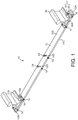
- Figure 1 illustrates an assembly 10 embodying the present invention.
- the assembly 10 is in place relative to two rails 40.
- the pictured rails 40 are disposed at a slight cant, so that they tilt inwards towards one another.
- a typical angle of cant is 1:20 or 2.86° for each rail 40.
- a beam 12 runs underneath both of the rails 40, and extends beyond the foot 40A of the rail 40 at either end.
- the beam 12 of the current embodiment is made of glass reinforced plastic, has cross sectional dimensions of 80mm x 20mm with a 5mm thick wall, and is 1.8m long.
- the extension 12A of the beam 12 beyond the foot 40A of the rail 40 enables a mounting bracket 14 to receive a beam-to-rail fastener 20 at a position outside the foot 40A of the rail 40.
- the beam 12 is pierced with six major holes 12D (not all visible in the Figures) over its length in three sets, the major holes 12D being open on the upper major surface 12B and lower major surface 12C of the beam 12.
- the middle set of major holes 12D is for the attachment of equipment, such as a balise, to the beam 12.
- the major holes 12D are adapted to receive respective mounting brackets 14, which in turn are adapted to receive equipment fastening means 24, such as a threaded fastener with a head portion.
- each set of holding means 17 comprises two clamping washers 18 and two beam-to-rail fasteners 20, although one of the clamping washers 18 is pictured without an accompanying beam-to-rail fastener 20 in place in order that the oval shape of a hole 18A provided in the clamping washer 18 for receiving the fastener 20 can be seen clearly.
- the beam 12 is adapted to receive a beam-to-rail fastener 20 into a bracket 14 at either side of each rail 40, hence there is a set of two major holes 12D toward either end of the beam 12.
- embodiments could use different numbers of clamping washers 18 and beam-to-rail fastening means 20 depending on factors such as weight of equipment, weight of beam 12, and susceptibility to vibration, amongst others.
- the number of major holes 12D required to attach the equipment will normally be two, but will depend on the particular piece of equipment to be mounted.
- a clamping washer 18 is an example of gripping means
- a beam-to-rail fastener 20 is an example of fastening means.
- each of the six major holes 12D are formed to accommodate the mounting brackets 14.
- each major hole 12D comprises a 20mm hole in the lower face 12C of the beam 12, and a 14mm hole in the upper surface 12B of the beam 12 concentric with the hole in the lower face 12C.
- the same mounting brackets 14 are used to mount the equipment to the beam 12 as are used to mount the beam 12 to the rail 40. This may vary depending on design considerations of particular embodiments, and it could even be that different mounting brackets 14 are used for some or each of the positions at which the beam 12 is mounted to the rail 40.
- the mounting brackets 14 are pushed up through the hole in the lower face 12C of the beam 12 so that they approach, or come into contact with, the underside of the upper face 12B of the beam 12.
- the mounting brackets 14 have a hole 14A running through them with a 14mm diameter to align with the major hole 12D in the beam 12.
- An anti-vibrational pad 16 is pictured beneath each rail 40, between the beam 12 and the rail 40.
- the adaptation of the anti-vibrational pads 16 to accommodate the cant of the rails 40 can be seen in Figure 1 , with the thickness of the pads 16 tapering towards the inside edge of the rail 40.
- the bottom surface 16B of each pad is substantially horizontal when in use, so the beam 12 can be held in position with its upper surface 12B flush against the bottom surface 16B of both the first and second anti-vibrational pads 16.
- the anti-vibrational pads 16 extend beyond the foot 40A of the rail 40, and are adapted to receive the beam-to-rail fasteners (fastening means) 20.
- the anti-vibrational pads 16 are adapted so that they can be placed on the beam 12 in such a way that holes 16C in the pads 16 are coincident with major holes 12D in the beam 12.
- a clamping washer 18 is positioned so that its hole 18A is coincident with the hole 16C in the anti-vibrational pad 16 and a major hole 12D in the beam 12.
- a beam-to-rail fastener 20 can then be received by the clamping washer 18 and the pad 16, and engage with the mounting bracket 14.
- the beam-to-rail fastener 20 has a threaded portion, and the mounting bracket 14 is correspondingly tapped, so that as it is tightened, the beam-to-rail fastener 20 pulls the assembly together.
- the clamping washer 18 is positioned so that a portion of its lower face 18B overlaps and grips an upper surface of the foot 40A of the rail 40, and the assembly is held in position relative to the rail 40 as the beam-to-rail fastener 20 is tightened.
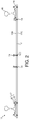
- Figure 2 presents a side view of the assembly of Figure 1 . Exemplary measurements and angles are provided.
- the angle of the cant of the rail 40 in Figure 2 is 3°, this is approximately typical of rail cants, although actual values vary depending on local standards.
- the gauge of the rail 40 in Figure 2 is 1436mm. Rail gauges vary from country to country, and even between railways within a given country. There is 190mm between the centres of the two holes forming a set of major holes 12D towards the end of the beam 12. This is wide enough to accommodate the foot 40A of the rail 40, and narrow enough that the clamping washers 18 can grip the upper surface of the foot 40A of the rail 40.
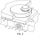
- Figure 3 provides a detail view of holding means 17 and the region of the assembly 10 around the foot 40A of the rail when attached to a rail 40.
- Figure 3 illustrates a mounting bracket 14 that has been pop riveted onto the beam 12.
- the bracket 14 In order to attach the mounting bracket 14 to the beam, the bracket 14 is clamped into position, and two minor holes are drilled on assembly through the fixing holes in the mounting bracket and into the side of the beam 12. The bracket 14 can then be pop riveted onto the beam 12, and the clamping force be removed. The bracket 14 is thus securely fixed in position.
- the anti-vibrational pad 16 lies on the upper surface 12B of the beam 12 and has a portion 16A between the beam 12 and the rail 40, and a portion 16D, 16E between the clamping washer 18 and the beam 12.
- the hole 16C (not pictured in Figure 3 ) in the anti-vibrational pad 16 is placed above the hole 12D in the upper surface 12B of the beam 12 to receive the beam-to-rail fastening means 20.
- the portion 16A of the pad 16 for placement between the beam 12 and the rail 40 is depressed with respect to the rest of the pad 16 so that the base of the foot 40A of the rail 40 fits into a depression in the pad 16.
- the clamping washer 18 can be positioned such that a portion 18B thereof overlaps the upper surface of the foot 40A of the rail 40, and a portion 18C bears onto the pad 16.
- a hole 18A in the clamping washer 18 aligns with a hole 16C in the pad 16 and a hole 12D in the beam 12.
- the clamping washer 18 is adapted to fit securely to the beam by having a recess 18D into which the upper surface of the foot 40A of the rail 40 can fit.
- the edge of the recess 18D aligns with the edge of the depression 16A in the anti-vibrational pad 16, so that the anti-vibrational pad 16 and the clamping washer 18 effectively form a c-shaped clamp about the foot 40A of the rail 40.
- This has the benefit of preventing lateral movement of the assembly with respect to the rail 40, particularly when the assembly 10 is clamped to the rail 40 in this way at either side of the foot 40A of the rail 40.
- the portion 18B of the clamping washer 18 positioned above the rail 40 has a serrated surface 18E to grip the rail 40 when the assembly 10 is secured in position.
- the mounting bracket 14 is held to the beam 12 by a pop rivet 26 in either side of the beam 12.
- the mounting bracket 14 features a central tubular portion 15 (see Figures 6 and 7 ) through which the hole 14A is formed.
- the tubular portion 15 protrudes upward from the base of the mounting bracket 14 when in place, and is received by the hole in the lower face 12C of the beam 12 so that the hole 14A through the tubular portion 15 aligns with the hole in the upper surface 12B of the beam 12, the hole 16C in the anti-vibrational pad 16, and the hole 18A in the clamping washer 18, to receive a beam-to-rail fastener 20.
- the diameter of the hole 14A in the tubular portion 15 approximately matches the diameter of the hole in the upper surface 12B of the beam 12, so that an upper surface 15A of the wall of the tubular portion 15 is against, or close to, the inner side of the upper surface 12B of the beam 12.
- the inner surface of the hole 14A in the tubular portion 15 is tapped, or internally threaded, so that when a beam-to-rail fastener 20, such as a threaded fastener, is in use, and received by the clamping washer 18, the anti-vibrational pad 16, and the beam 12, the fastener 20 pulls against the bracket 14.
- the pulling or clamping force is transmitted through the bracket 14 to the upper surface 12B of the beam 12 so that the beam is not crushed by the clamping force and the majority of the clamping force is withstood by the compressive strength of the upper surface 12B of the beam 12.
- Washers 28 can be used between the clamping washer 18 and the head of the beam-to-rail fastener 20 to have an anti-vibrational effect.
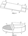
- FIG. 4 shows an anti-vibrational pad 16 forming part of an assembly 10 embodying the present invention.
- the anti-vibrational pad 16 is composed of rubber, but any material which, when used as part of an assembly 10 embodying the present invention, would have a damping effect on vibrations can be used.
- a central portion 16A of the pad 16 is depressed to receive the rail 40. Beyond either end of the central depressed portion 16A is a portion 16D, 16E of the pad 16 which is thicker than its respective end of the depressed portion 16A and the upper surfaces of the thicker portions 16D, 16E are therefore raised with respect to the depressed portion 16A.
- the thickness, and hence the height, of the pad 16 varies across the width of the depressed portion 16A to accommodate the rail cant.
- each thicker portion 16D, 16E is a hole 16C, adapted to receive the beam-to-rail fastener 20.
- the oval shape of the hole 16C allows for variations in the width of the rail foot 40A to be accommodated. Variations in the width of a rail foot 40A could be due to variations in local standards, or could be due to physical factors such as thermal variation.
- the depressed portion 16A can be adapted so that it closely reflects the profile of the bottom surface of the rail foot 40A. This not only enhances the anti-vibrational effects of the pad 16, but also prevents any lateral movement of the pad 16 with respect to the rail 40.
- FIG. 5 shows a clamping washer 18 forming part of an assembly 10 embodying the present invention.
- the clamping washer 18 of Figure 5 is essentially a broad cylinder incorporating a recess.
- the recess gives rise to a thinner portion 18B, a surface 18E of which edges the recess, and is serrated for gripping the rail.
- the serrated surface 18E clamps down on an upper surface of the foot 40A of the rail 40 so that the serrated surface 18E is a bottom surface of the thinner portion 18B. Since the thinner portion 18B is adapted for clamping down on the rail 40 when in use, a hole 18A for receiving the beam-to-rail fastening means 20 runs through the thicker portion 18C of the washer 18.
- the inner corner of the recess has a curved edge 18D, which incorporates the foot 40A of the rail 40.
- the edge between the thinner portion 18B and thicker portion 18C of the washer 18 should approximately align with an edge of the depressed portion 16A of the anti-vibrational pad 16, so that the pad 16 and washer 18 effectively form a c-shaped clamp about the foot 40A of the rail 40.
- the hole 18A in the clamping washer 18 for receiving the beam-to-rail fastening means 20 is oval-shaped.
- the hole passes through the thicker portion 18C of the washer 18. The oval shape allows for variations in the width of the rail foot 40A to be accommodated.
- the holding means 17 comprise a clamping washer 18 and a beam-to-rail fastener 20 at both an inside position and an outside position of a canted rail 40
- the clamping washer 18 may be desirable for the clamping washer 18 to be adapted so that the serrated surface 18E can strongly grip the upper surface 12B of the foot 40A of the rail 40, regardless of whether the particular washer 18 is used on the inside or the outside position.
- surfaces of the thicker portions of the anti-vibrational pad 16 onto which the clamping washer 18 bears are both substantially horizontal, and the top surface of the foot 40A of the rail 40 at the outer edges onto which the washer would clamp are at an angle ⁇ relative to the bottom surface of the foot 40A of the rail.
- the angles of the top surfaces of the foot 40A of the rail at the outer edges relative to the substantially horizontal top surfaces of the pad 16, are ⁇ + ⁇ at one side, and ⁇ - ⁇ at the other. Since the clamping washer 18 when in use bears onto the substantially horizontal top surface of the thicker portions of the pad 16, the same difference in angles of surfaces of the washer 18 relative to angles of surfaces of the foot 40A of the rail exists between the inside and outside rail positions.
- the serrated surface 18E of the clamping washer 18 has teeth cut into the clamping surface at two distinct angles to ensure that some of the teeth match the angle of the top surface of the foot 40A of the rail at an inside position of the rail 40, and some match the angle of the top surface of the foot 40A of the rail at an outside position of the rail 40.
- the beam-to-rail fastener 20 can be a screw having a threaded portion which engages with an internally threaded, or tapped, tubular portion of the mounting bracket 14, and a head portion, which is wider than the threaded portion so that when the assembly is in place on the rail, the wider head portion is not received by the hole in the clamping washer 18, and the clamping washer 18, the anti-vibrational pad 16, the beam 12, and the mounting bracket 14, are held in place against the foot 40A of the rail 40.
- Some embodiments incorporate further washers between the head portion of the beam-to-rail fastening means 20 and the clamping washer 18. These further washers may be adapted to enhance the anti-vibrational properties of the assembly 10.
- FIGS 6 and 7 illustrate cast and fabricated constructions of a mounting bracket 14, respectively.
- the mounting brackets 14 both feature side portions 14B at either end of the bracket, joined by a base portion 14C, and have a tubular portion 15 protruding from the base portion 14C.
- Stainless steel would be a suitable material for manufacturing a mounting bracket, having good resistance to rust, and good compressive strength.
- Each end portion has a fixing hole 14D which aligns with a minor hole in the side of the beam 12 to enable the bracket 14 to be pop riveted to the beam 12.
- the tubular portion 15 of the bracket 14 is received by a hole in the lower face 12C of the beam 12, and an upper surface 15A of the wall of the tubular portion 15 thus approaches or contacts the inside of the upper surface 12B of the beam 12.
- the upper surface 12B of the beam 12 has a hole smaller in diameter than the hole in the lower face 12C of the beam 12, and approximately equal in diameter with the hole 14A through the tubular portion 15 of the bracket 14.
- the hole 14A through the tubular portion 15 of the mounting bracket 14 is tapped (not pictured) to enable the beam-to-rail fastener 20, or equipment fastening means 24, to pull on the mounting bracket 14. It is this pulling force that effectively holds the assembly 10 together.
- mounting brackets 14 may be used to receive a beam-to-rail fastener 20, but equally may be used to receive equipment fastening means 24.
Landscapes
- Engineering & Computer Science (AREA)
- Architecture (AREA)
- Civil Engineering (AREA)
- Structural Engineering (AREA)
- Mechanical Engineering (AREA)
- Railway Tracks (AREA)
Claims (9)
- Ensemble de montage d'équipement (10) pour monter un équipement sur une voie ferrée, la voie ferrée ayant des premier et second rails (40) sur lesquels l'équipement doit être monté, les rails (40) s'étendant parallèlement l'un à l'autre et étant supportés sur des fondations de rail, l'ensemble (10) comprenant :une poutre (12) destinée à être connectée aux deux rails (40), poutre (12) sur laquelle l'équipement peut être monté ; etdes premier et second moyens de maintien (17) pour maintenir la poutre (12) en position par rapport aux rails, les premier et second moyens de maintien (17) étant configurés pour supporter la poutre (12) sous les rails (40) dans un agencement dans lequel la poutre (12) réside dans un espace situé entre deux fondations de rail adjacentes ;caractérisé en ce que la poutre (12) est non métallique et en ce que l'ensemble (10) comprend en outre des premier et second patins anti-vibration (16) destinés à être placés entre la poutre (12) et le rail (40) et à être localisés à chaque extrémité de la poutre (12), chacun des premier et second patins anti-vibration (16) ayant une partie (16A) qui est enfoncée par rapport au reste du patin (16), et des parties supplémentaires (16D, 16E) qui s'étendent au-delà des bords du pied (40A) du rail correspondant (40) lorsque le patin (16) est en position sous le rail (40), de sorte qu'en utilisation, la partie enfoncée (16A) du patin (16) se trouve entre une face supérieure (12B) de la poutre (12) et un pied (40A) de l'un correspondant des rails (40), et chacun des moyens de maintien (17) est adapté pour venir en appui sur l'un associé des patins anti-vibration (16).
- Ensemble selon la revendication 1, dans lequel
les premier et second moyens de maintien (17) comprennent chacun un moyen de préhension (18) et un moyen de fixation (20) ;
la poutre (12), chaque patin anti-vibration (16) et chacun des moyens de préhension (18) sont adaptés pour recevoir un associé des moyens de fixation (20) ; et
chacun des premier et second moyens de maintien (17) est adapté pour que lorsque son moyen de fixation (20) est reçu par le moyen de préhension associé (18), un associé des patins anti-vibration (16) et la poutre (12), le moyen de préhension (18) peut être utilisé pour serrer sur une surface supérieure du pied (40A) du rail correspondant (40) et sur la partie supplémentaire du patin anti-vibration associé (16) qui se situe entre les moyens de préhension (18) et la poutre (12). - Ensemble selon la revendication 1 ou 2, dans lequel la poutre (12) est creuse.
- Ensemble selon la revendication 2 ou la revendication 3 lorsqu'elle est annexée à la revendication 2, comprenant en outre des premier et second supports de montage (14), dans lequel
la poutre (12) est adaptée pour recevoir chacun des premier et second supports de montage (14) ; et
les premier et second supports de montage (14) sont adaptés pour être montés sur la poutre (12) et recevoir les moyens de fixation (20) à l'intérieur de la poutre (12) de sorte que la poutre (12) soit renforcée contre des forces exercées via les moyens de fixation (20). - Ensemble selon la revendication 2 ou 4, ou la revendication 3 lorsqu'elle est annexée à la revendication 2, dans lequel le moyen de fixation (20) est une fixation filetée, et le support de montage (14) est taraudé pour recevoir la fixation filetée.
- Ensemble selon l'une quelconque des revendications précédentes, dans lequel l'épaisseur de chaque patin anti-vibration (16) diminue de telle sorte que le patin anti-vibration (16) est adapté pour recevoir une inclinaison de rail spécifique.
- Ensemble selon l'une quelconque des revendications 2 à 6, dans lequel chacun des moyens de préhension (18) comprend une rondelle de serrage ayant une surface inférieure avec une partie dentelée (18E) pour saisir la surface supérieure du pied (40A) du rail (40).
- Ensemble selon l'une quelconque des revendications 2 à 7, dans lequel chacun des moyens de préhension (18) comporte un trou ovale (18A) destiné à recevoir le moyen de fixation (20) de sorte qu'une variation de largeur de rail peut être compensée par le moyen de préhension (18).
- Ensemble selon la revendication 7, ou la revendication 8 lorsque lue comme annexée à la revendication 7, dans lequel la partie dentelée (18E) a des dents découpées dans sa surface inférieure sur deux angles distincts :un premier angle pour correspondre à la surface supérieure du pied (40A) du rail (40) sur un côté proche du rail par rapport à l'autre rail ; etun second angle pour apparier la surface supérieure du pied (40A) du rail (40) sur un côté éloigné du rail par rapport à l'autre rail.
Priority Applications (1)
| Application Number | Priority Date | Filing Date | Title |
|---|---|---|---|
| PL10166639T PL2281943T3 (pl) | 2009-06-22 | 2010-06-21 | Zespół montażowy wyposażenia |
Applications Claiming Priority (1)
| Application Number | Priority Date | Filing Date | Title |
|---|---|---|---|
| GB0910731.9A GB2471277B (en) | 2009-06-22 | 2009-06-22 | Equipment mounting assembly |
Publications (4)
| Publication Number | Publication Date |
|---|---|
| EP2281943A2 EP2281943A2 (fr) | 2011-02-09 |
| EP2281943A3 EP2281943A3 (fr) | 2013-12-18 |
| EP2281943B1 true EP2281943B1 (fr) | 2019-08-07 |
| EP2281943B8 EP2281943B8 (fr) | 2019-09-11 |
Family
ID=40972556
Family Applications (1)
| Application Number | Title | Priority Date | Filing Date |
|---|---|---|---|
| EP10166639.4A Active EP2281943B8 (fr) | 2009-06-22 | 2010-06-21 | Ensemble de montage d'équipement |
Country Status (5)
| Country | Link |
|---|---|
| EP (1) | EP2281943B8 (fr) |
| DK (1) | DK2281943T3 (fr) |
| ES (1) | ES2753139T3 (fr) |
| GB (1) | GB2471277B (fr) |
| PL (1) | PL2281943T3 (fr) |
Families Citing this family (4)
| Publication number | Priority date | Publication date | Assignee | Title |
|---|---|---|---|---|
| EP3210846A1 (fr) * | 2016-02-26 | 2017-08-30 | Siemens Schweiz AG | Dispositif de disposition temporaire d'une balise dans une voie formee de deux contre-aiguilles |
| RU191992U1 (ru) * | 2019-02-22 | 2019-08-29 | Федеральное государственное бюджетное образовательное учреждение высшего образования "Петербургский государственный университет путей сообщения Императора Александра I" | Реборчатая подкладка |
| GB2583722B (en) * | 2019-05-03 | 2022-05-18 | Pandrol Vortok Ltd | Rail clamp connector |
| CN111519478B (zh) * | 2020-04-08 | 2021-09-14 | 陈立辉 | 一种轨道交通用轨距拉杆 |
Family Cites Families (7)
| Publication number | Priority date | Publication date | Assignee | Title |
|---|---|---|---|---|
| US3877640A (en) * | 1974-07-18 | 1975-04-15 | Raghuram Shripad Hemmady | Railroad cross supports and process for maintenance of track bed |
| US5314115A (en) * | 1992-05-27 | 1994-05-24 | Bombardier Inc. | Rail cross-tie for LIM transit system |
| DE19548857C2 (de) * | 1995-12-27 | 2000-03-09 | Envitec Umweltsyst Gmbh & Co | Abdeckung für Gleisanlagen |
| GB9826674D0 (en) * | 1998-12-03 | 1999-01-27 | Multiclip Co Ltd | Securing an aerial fixation assembly to a railway rail foundation |
| DE20116007U1 (de) * | 2001-09-28 | 2002-01-31 | Köhler + Seitz Beraten und Planen GmbH, 90441 Nürnberg | Einrichtung zur Sicherung von Absturzkanten und zur Errichtung von Dienstwegen neben Gleisen |
| TWI260360B (en) * | 2003-05-06 | 2006-08-21 | Bombardier Transp Gmbh | Cross-tie |
| FR2885916B1 (fr) * | 2005-05-19 | 2007-10-19 | Csee Transp Sarl | Dispositif de maintien sur une traverse de voie ferree |
-
2009
- 2009-06-22 GB GB0910731.9A patent/GB2471277B/en active Active
-
2010
- 2010-06-21 PL PL10166639T patent/PL2281943T3/pl unknown
- 2010-06-21 ES ES10166639T patent/ES2753139T3/es active Active
- 2010-06-21 DK DK10166639T patent/DK2281943T3/da active
- 2010-06-21 EP EP10166639.4A patent/EP2281943B8/fr active Active
Non-Patent Citations (1)
| Title |
|---|
| None * |
Also Published As
| Publication number | Publication date |
|---|---|
| GB0910731D0 (en) | 2009-08-05 |
| PL2281943T3 (pl) | 2020-06-01 |
| GB2471277B (en) | 2016-04-27 |
| EP2281943B8 (fr) | 2019-09-11 |
| ES2753139T3 (es) | 2020-04-07 |
| DK2281943T3 (da) | 2019-11-11 |
| EP2281943A2 (fr) | 2011-02-09 |
| GB2471277A (en) | 2010-12-29 |
| EP2281943A3 (fr) | 2013-12-18 |
Similar Documents
| Publication | Publication Date | Title |
|---|---|---|
| EP2281943B1 (fr) | Ensemble de montage d'équipement | |
| CA2805877C (fr) | Dispositif de fixation | |
| CN102272382B (zh) | 弹性弹条扣件以及借助其的轨道固定 | |
| JP2003519611A (ja) | クレーン軌道支持架構 | |
| BR112014010111B1 (pt) | dispositivo de fixação elástica para trilho | |
| KR20190014007A (ko) | 크레인 레일 기초 고정용 높이 조절 클립 | |
| JP2005515106A5 (fr) | ||
| AU2013286205B2 (en) | Device for fastening a rail to a carrier | |
| CA2640845C (fr) | Appareil d'attache pour rail suspendu | |
| RS63110B1 (sr) | Zatezne stege za priključivanje šine za podlogu | |
| CN107435283B (zh) | 用于固定用于轨道车辆的轨道的装置 | |
| US4119271A (en) | Rail bracing system | |
| CN109211383B (zh) | 一种框架式轨道称重传感器 | |
| EP3612677B1 (fr) | Système de fixation d'un rail, procédés pour la réalisation d'un système de fixation et de support d'un rail et utilisation d'une fixation de rail | |
| AU5721890A (en) | Guide rail mounting | |
| KR20170075480A (ko) | 철도용 레일 지지장치 | |
| WO2014118798A1 (fr) | Attache de rail élastique antivol muni d'un dispositif de fixation d'ancre | |
| KR200420885Y1 (ko) | 철재구조물에 설치되는 레일의 절연 체결장치 | |
| CN108755291B (zh) | 一种非对称式钢轨扣件系统 | |
| WO2006130078A1 (fr) | Patte de fixation d'un porte-charge | |
| JP2506127Y2 (ja) | レ―ル締結装置におけるコンクリ―ト枕木横圧補強装置 | |
| JPH0230481Y2 (fr) | ||
| JP2000230201A (ja) | 枕木構造 | |
| KR200410829Y1 (ko) | 급커브 철도 레일의 체결장치 | |
| JPH0540183Y2 (fr) |
Legal Events
| Date | Code | Title | Description |
|---|---|---|---|
| PUAI | Public reference made under article 153(3) epc to a published international application that has entered the european phase |
Free format text: ORIGINAL CODE: 0009012 |
|
| AK | Designated contracting states |
Kind code of ref document: A2 Designated state(s): AL AT BE BG CH CY CZ DE DK EE ES FI FR GB GR HR HU IE IS IT LI LT LU LV MC MK MT NL NO PL PT RO SE SI SK SM TR |
|
| AX | Request for extension of the european patent |
Extension state: BA ME RS |
|
| PUAL | Search report despatched |
Free format text: ORIGINAL CODE: 0009013 |
|
| AK | Designated contracting states |
Kind code of ref document: A3 Designated state(s): AL AT BE BG CH CY CZ DE DK EE ES FI FR GB GR HR HU IE IS IT LI LT LU LV MC MK MT NL NO PL PT RO SE SI SK SM TR |
|
| AX | Request for extension of the european patent |
Extension state: BA ME RS |
|
| RIC1 | Information provided on ipc code assigned before grant |
Ipc: B61L 1/02 20060101ALI20131114BHEP Ipc: F16B 37/00 20060101ALI20131114BHEP Ipc: E01B 26/00 20060101ALI20131114BHEP Ipc: E01B 9/00 20060101AFI20131114BHEP Ipc: F16B 5/02 20060101ALI20131114BHEP |
|
| 17P | Request for examination filed |
Effective date: 20140611 |
|
| RBV | Designated contracting states (corrected) |
Designated state(s): AL AT BE BG CH CY CZ DE DK EE ES FI FR GB GR HR HU IE IS IT LI LT LU LV MC MK MT NL NO PL PT RO SE SI SK SM TR |
|
| 17Q | First examination report despatched |
Effective date: 20150512 |
|
| STAA | Information on the status of an ep patent application or granted ep patent |
Free format text: STATUS: EXAMINATION IS IN PROGRESS |
|
| REG | Reference to a national code |
Ref country code: DE Ref legal event code: R079 Ref document number: 602010060374 Country of ref document: DE Free format text: PREVIOUS MAIN CLASS: E01B0009000000 Ipc: E01B0005160000 |
|
| GRAP | Despatch of communication of intention to grant a patent |
Free format text: ORIGINAL CODE: EPIDOSNIGR1 |
|
| STAA | Information on the status of an ep patent application or granted ep patent |
Free format text: STATUS: GRANT OF PATENT IS INTENDED |
|
| INTG | Intention to grant announced |
Effective date: 20181214 |
|
| RIC1 | Information provided on ipc code assigned before grant |
Ipc: B61L 3/12 20060101ALI20181130BHEP Ipc: F16B 37/00 20060101ALI20181130BHEP Ipc: E01B 9/00 20060101ALI20181130BHEP Ipc: B61L 1/02 20060101ALI20181130BHEP Ipc: E01B 26/00 20060101ALI20181130BHEP Ipc: F16B 5/02 20060101ALI20181130BHEP Ipc: E01B 5/16 20060101AFI20181130BHEP |
|
| GRAJ | Information related to disapproval of communication of intention to grant by the applicant or resumption of examination proceedings by the epo deleted |
Free format text: ORIGINAL CODE: EPIDOSDIGR1 |
|
| STAA | Information on the status of an ep patent application or granted ep patent |
Free format text: STATUS: EXAMINATION IS IN PROGRESS |
|
| INTC | Intention to grant announced (deleted) | ||
| GRAR | Information related to intention to grant a patent recorded |
Free format text: ORIGINAL CODE: EPIDOSNIGR71 |
|
| GRAS | Grant fee paid |
Free format text: ORIGINAL CODE: EPIDOSNIGR3 |
|
| STAA | Information on the status of an ep patent application or granted ep patent |
Free format text: STATUS: GRANT OF PATENT IS INTENDED |
|
| RAP1 | Party data changed (applicant data changed or rights of an application transferred) |
Owner name: PANDROL (VORTOK) LIMITED |
|
| INTG | Intention to grant announced |
Effective date: 20190524 |
|
| GRAA | (expected) grant |
Free format text: ORIGINAL CODE: 0009210 |
|
| STAA | Information on the status of an ep patent application or granted ep patent |
Free format text: STATUS: THE PATENT HAS BEEN GRANTED |
|
| AK | Designated contracting states |
Kind code of ref document: B1 Designated state(s): AL AT BE BG CH CY CZ DE DK EE ES FI FR GB GR HR HU IE IS IT LI LT LU LV MC MK MT NL NO PL PT RO SE SI SK SM TR |
|
| REG | Reference to a national code |
Ref country code: GB Ref legal event code: FG4D |
|
| REG | Reference to a national code |
Ref country code: CH Ref legal event code: EP Ref country code: CH Ref legal event code: PK Free format text: BERICHTIGUNG B8 Ref country code: AT Ref legal event code: REF Ref document number: 1164072 Country of ref document: AT Kind code of ref document: T Effective date: 20190815 |
|
| RBV | Designated contracting states (corrected) |
Designated state(s): AL AT BE BG CH CY CZ DE DK EE ES FI FR GR HR HU IE IS IT LI LT LU LV MC MK MT NL NO PL PT RO SE SI SK SM TR |
|
| REG | Reference to a national code |
Ref country code: DE Ref legal event code: R096 Ref document number: 602010060374 Country of ref document: DE |
|
| REG | Reference to a national code |
Ref country code: SE Ref legal event code: TRGR |
|
| REG | Reference to a national code |
Ref country code: NL Ref legal event code: FP Ref country code: IE Ref legal event code: FG4D |
|
| REG | Reference to a national code |
Ref country code: CH Ref legal event code: NV Representative=s name: DR. LUSUARDI AG, CH |
|
| REG | Reference to a national code |
Ref country code: DK Ref legal event code: T3 Effective date: 20191108 |
|
| REG | Reference to a national code |
Ref country code: NO Ref legal event code: T2 Effective date: 20190807 |
|
| REG | Reference to a national code |
Ref country code: LT Ref legal event code: MG4D |
|
| PG25 | Lapsed in a contracting state [announced via postgrant information from national office to epo] |
Ref country code: PT Free format text: LAPSE BECAUSE OF FAILURE TO SUBMIT A TRANSLATION OF THE DESCRIPTION OR TO PAY THE FEE WITHIN THE PRESCRIBED TIME-LIMIT Effective date: 20191209 Ref country code: HR Free format text: LAPSE BECAUSE OF FAILURE TO SUBMIT A TRANSLATION OF THE DESCRIPTION OR TO PAY THE FEE WITHIN THE PRESCRIBED TIME-LIMIT Effective date: 20190807 Ref country code: LT Free format text: LAPSE BECAUSE OF FAILURE TO SUBMIT A TRANSLATION OF THE DESCRIPTION OR TO PAY THE FEE WITHIN THE PRESCRIBED TIME-LIMIT Effective date: 20190807 Ref country code: BG Free format text: LAPSE BECAUSE OF FAILURE TO SUBMIT A TRANSLATION OF THE DESCRIPTION OR TO PAY THE FEE WITHIN THE PRESCRIBED TIME-LIMIT Effective date: 20191107 |
|
| PG25 | Lapsed in a contracting state [announced via postgrant information from national office to epo] |
Ref country code: IS Free format text: LAPSE BECAUSE OF FAILURE TO SUBMIT A TRANSLATION OF THE DESCRIPTION OR TO PAY THE FEE WITHIN THE PRESCRIBED TIME-LIMIT Effective date: 20191207 Ref country code: LV Free format text: LAPSE BECAUSE OF FAILURE TO SUBMIT A TRANSLATION OF THE DESCRIPTION OR TO PAY THE FEE WITHIN THE PRESCRIBED TIME-LIMIT Effective date: 20190807 Ref country code: GR Free format text: LAPSE BECAUSE OF FAILURE TO SUBMIT A TRANSLATION OF THE DESCRIPTION OR TO PAY THE FEE WITHIN THE PRESCRIBED TIME-LIMIT Effective date: 20191108 Ref country code: AL Free format text: LAPSE BECAUSE OF FAILURE TO SUBMIT A TRANSLATION OF THE DESCRIPTION OR TO PAY THE FEE WITHIN THE PRESCRIBED TIME-LIMIT Effective date: 20190807 |
|
| PG25 | Lapsed in a contracting state [announced via postgrant information from national office to epo] |
Ref country code: TR Free format text: LAPSE BECAUSE OF FAILURE TO SUBMIT A TRANSLATION OF THE DESCRIPTION OR TO PAY THE FEE WITHIN THE PRESCRIBED TIME-LIMIT Effective date: 20190807 |
|
| REG | Reference to a national code |
Ref country code: ES Ref legal event code: FG2A Ref document number: 2753139 Country of ref document: ES Kind code of ref document: T3 Effective date: 20200407 |
|
| PG25 | Lapsed in a contracting state [announced via postgrant information from national office to epo] |
Ref country code: RO Free format text: LAPSE BECAUSE OF FAILURE TO SUBMIT A TRANSLATION OF THE DESCRIPTION OR TO PAY THE FEE WITHIN THE PRESCRIBED TIME-LIMIT Effective date: 20190807 Ref country code: EE Free format text: LAPSE BECAUSE OF FAILURE TO SUBMIT A TRANSLATION OF THE DESCRIPTION OR TO PAY THE FEE WITHIN THE PRESCRIBED TIME-LIMIT Effective date: 20190807 |
|
| PG25 | Lapsed in a contracting state [announced via postgrant information from national office to epo] |
Ref country code: SK Free format text: LAPSE BECAUSE OF FAILURE TO SUBMIT A TRANSLATION OF THE DESCRIPTION OR TO PAY THE FEE WITHIN THE PRESCRIBED TIME-LIMIT Effective date: 20190807 Ref country code: IS Free format text: LAPSE BECAUSE OF FAILURE TO SUBMIT A TRANSLATION OF THE DESCRIPTION OR TO PAY THE FEE WITHIN THE PRESCRIBED TIME-LIMIT Effective date: 20200224 Ref country code: SM Free format text: LAPSE BECAUSE OF FAILURE TO SUBMIT A TRANSLATION OF THE DESCRIPTION OR TO PAY THE FEE WITHIN THE PRESCRIBED TIME-LIMIT Effective date: 20190807 |
|
| REG | Reference to a national code |
Ref country code: DE Ref legal event code: R097 Ref document number: 602010060374 Country of ref document: DE |
|
| PLBE | No opposition filed within time limit |
Free format text: ORIGINAL CODE: 0009261 |
|
| STAA | Information on the status of an ep patent application or granted ep patent |
Free format text: STATUS: NO OPPOSITION FILED WITHIN TIME LIMIT |
|
| PG2D | Information on lapse in contracting state deleted |
Ref country code: IS |
|
| 26N | No opposition filed |
Effective date: 20200603 |
|
| PG25 | Lapsed in a contracting state [announced via postgrant information from national office to epo] |
Ref country code: SI Free format text: LAPSE BECAUSE OF FAILURE TO SUBMIT A TRANSLATION OF THE DESCRIPTION OR TO PAY THE FEE WITHIN THE PRESCRIBED TIME-LIMIT Effective date: 20190807 |
|
| REG | Reference to a national code |
Ref country code: DE Ref legal event code: R082 Ref document number: 602010060374 Country of ref document: DE Representative=s name: HL KEMPNER PATENTANWAELTE, SOLICITORS (ENGLAND, DE Ref country code: DE Ref legal event code: R082 Ref document number: 602010060374 Country of ref document: DE Representative=s name: HL KEMPNER PARTG MBB, DE Ref country code: DE Ref legal event code: R082 Ref document number: 602010060374 Country of ref document: DE Representative=s name: HL KEMPNER PATENTANWALT, RECHTSANWALT, SOLICIT, DE |
|
| PG25 | Lapsed in a contracting state [announced via postgrant information from national office to epo] |
Ref country code: MC Free format text: LAPSE BECAUSE OF FAILURE TO SUBMIT A TRANSLATION OF THE DESCRIPTION OR TO PAY THE FEE WITHIN THE PRESCRIBED TIME-LIMIT Effective date: 20190807 |
|
| PG25 | Lapsed in a contracting state [announced via postgrant information from national office to epo] |
Ref country code: LU Free format text: LAPSE BECAUSE OF NON-PAYMENT OF DUE FEES Effective date: 20200621 |
|
| PG25 | Lapsed in a contracting state [announced via postgrant information from national office to epo] |
Ref country code: IE Free format text: LAPSE BECAUSE OF NON-PAYMENT OF DUE FEES Effective date: 20200621 |
|
| REG | Reference to a national code |
Ref country code: AT Ref legal event code: UEP Ref document number: 1164072 Country of ref document: AT Kind code of ref document: T Effective date: 20190807 |
|
| PG25 | Lapsed in a contracting state [announced via postgrant information from national office to epo] |
Ref country code: MT Free format text: LAPSE BECAUSE OF FAILURE TO SUBMIT A TRANSLATION OF THE DESCRIPTION OR TO PAY THE FEE WITHIN THE PRESCRIBED TIME-LIMIT Effective date: 20190807 Ref country code: CY Free format text: LAPSE BECAUSE OF FAILURE TO SUBMIT A TRANSLATION OF THE DESCRIPTION OR TO PAY THE FEE WITHIN THE PRESCRIBED TIME-LIMIT Effective date: 20190807 |
|
| PG25 | Lapsed in a contracting state [announced via postgrant information from national office to epo] |
Ref country code: MK Free format text: LAPSE BECAUSE OF FAILURE TO SUBMIT A TRANSLATION OF THE DESCRIPTION OR TO PAY THE FEE WITHIN THE PRESCRIBED TIME-LIMIT Effective date: 20190807 |
|
| P01 | Opt-out of the competence of the unified patent court (upc) registered |
Effective date: 20230330 |
|
| PGFP | Annual fee paid to national office [announced via postgrant information from national office to epo] |
Ref country code: FI Payment date: 20250613 Year of fee payment: 16 |
|
| PGFP | Annual fee paid to national office [announced via postgrant information from national office to epo] |
Ref country code: DE Payment date: 20250623 Year of fee payment: 16 Ref country code: PL Payment date: 20250605 Year of fee payment: 16 |
|
| PGFP | Annual fee paid to national office [announced via postgrant information from national office to epo] |
Ref country code: DK Payment date: 20250623 Year of fee payment: 16 |
|
| PGFP | Annual fee paid to national office [announced via postgrant information from national office to epo] |
Ref country code: NO Payment date: 20250610 Year of fee payment: 16 |
|
| PGFP | Annual fee paid to national office [announced via postgrant information from national office to epo] |
Ref country code: NL Payment date: 20250623 Year of fee payment: 16 Ref country code: BE Payment date: 20250611 Year of fee payment: 16 |
|
| PGFP | Annual fee paid to national office [announced via postgrant information from national office to epo] |
Ref country code: FR Payment date: 20250611 Year of fee payment: 16 |
|
| PGFP | Annual fee paid to national office [announced via postgrant information from national office to epo] |
Ref country code: AT Payment date: 20250610 Year of fee payment: 16 |
|
| PGFP | Annual fee paid to national office [announced via postgrant information from national office to epo] |
Ref country code: CZ Payment date: 20250611 Year of fee payment: 16 |
|
| PGFP | Annual fee paid to national office [announced via postgrant information from national office to epo] |
Ref country code: SE Payment date: 20250624 Year of fee payment: 16 |
|
| PGFP | Annual fee paid to national office [announced via postgrant information from national office to epo] |
Ref country code: ES Payment date: 20250702 Year of fee payment: 16 |
|
| PGFP | Annual fee paid to national office [announced via postgrant information from national office to epo] |
Ref country code: IT Payment date: 20250613 Year of fee payment: 16 |
|
| PGFP | Annual fee paid to national office [announced via postgrant information from national office to epo] |
Ref country code: CH Payment date: 20250701 Year of fee payment: 16 |