EP2282130A2 - Dispositif de réduction de la quantité d'évaporation d'un moyen de refroidissement dans le circuit de refroidissement d'une installation de couplage force-chaleur - Google Patents
Dispositif de réduction de la quantité d'évaporation d'un moyen de refroidissement dans le circuit de refroidissement d'une installation de couplage force-chaleur Download PDFInfo
- Publication number
- EP2282130A2 EP2282130A2 EP10006376A EP10006376A EP2282130A2 EP 2282130 A2 EP2282130 A2 EP 2282130A2 EP 10006376 A EP10006376 A EP 10006376A EP 10006376 A EP10006376 A EP 10006376A EP 2282130 A2 EP2282130 A2 EP 2282130A2
- Authority
- EP
- European Patent Office
- Prior art keywords
- coolant
- power plant
- combined heat
- line
- arrangement
- Prior art date
- Legal status (The legal status is an assumption and is not a legal conclusion. Google has not performed a legal analysis and makes no representation as to the accuracy of the status listed.)
- Withdrawn
Links
- 239000002826 coolant Substances 0.000 title claims abstract description 122
- 238000001704 evaporation Methods 0.000 title description 12
- 238000010438 heat treatment Methods 0.000 claims abstract description 13
- 238000001816 cooling Methods 0.000 claims abstract description 10
- 238000009423 ventilation Methods 0.000 claims abstract description 7
- 239000004020 conductor Substances 0.000 claims abstract description 4
- 238000013022 venting Methods 0.000 claims description 5
- 230000001105 regulatory effect Effects 0.000 claims description 3
- 230000008020 evaporation Effects 0.000 description 11
- 239000002184 metal Substances 0.000 description 6
- 229910052751 metal Inorganic materials 0.000 description 6
- 241000711969 Chandipura virus Species 0.000 description 5
- 239000008236 heating water Substances 0.000 description 3
- 238000009434 installation Methods 0.000 description 3
- 230000033228 biological regulation Effects 0.000 description 2
- 239000000498 cooling water Substances 0.000 description 2
- 230000001419 dependent effect Effects 0.000 description 2
- 238000000605 extraction Methods 0.000 description 2
- RYGMFSIKBFXOCR-UHFFFAOYSA-N Copper Chemical compound [Cu] RYGMFSIKBFXOCR-UHFFFAOYSA-N 0.000 description 1
- 230000001174 ascending effect Effects 0.000 description 1
- 238000010276 construction Methods 0.000 description 1
- 229910052802 copper Inorganic materials 0.000 description 1
- 239000010949 copper Substances 0.000 description 1
- 230000007423 decrease Effects 0.000 description 1
- 239000000945 filler Substances 0.000 description 1
- 230000017525 heat dissipation Effects 0.000 description 1
- 238000000034 method Methods 0.000 description 1
- 239000012071 phase Substances 0.000 description 1
- 230000007704 transition Effects 0.000 description 1
- 238000011144 upstream manufacturing Methods 0.000 description 1
- 239000012808 vapor phase Substances 0.000 description 1
- XLYOFNOQVPJJNP-UHFFFAOYSA-N water Substances O XLYOFNOQVPJJNP-UHFFFAOYSA-N 0.000 description 1
Images


Classifications
-
- F—MECHANICAL ENGINEERING; LIGHTING; HEATING; WEAPONS; BLASTING
- F24—HEATING; RANGES; VENTILATING
- F24D—DOMESTIC- OR SPACE-HEATING SYSTEMS, e.g. CENTRAL HEATING SYSTEMS; DOMESTIC HOT-WATER SUPPLY SYSTEMS; ELEMENTS OR COMPONENTS THEREFOR
- F24D11/00—Central heating systems using heat accumulated in storage masses
- F24D11/002—Central heating systems using heat accumulated in storage masses water heating system
- F24D11/005—Central heating systems using heat accumulated in storage masses water heating system with recuperation of waste heat
-
- F—MECHANICAL ENGINEERING; LIGHTING; HEATING; WEAPONS; BLASTING
- F24—HEATING; RANGES; VENTILATING
- F24D—DOMESTIC- OR SPACE-HEATING SYSTEMS, e.g. CENTRAL HEATING SYSTEMS; DOMESTIC HOT-WATER SUPPLY SYSTEMS; ELEMENTS OR COMPONENTS THEREFOR
- F24D19/00—Details
- F24D19/08—Arrangements for drainage, venting or aerating
- F24D19/082—Arrangements for drainage, venting or aerating for water heating systems
- F24D19/083—Venting arrangements
-
- F—MECHANICAL ENGINEERING; LIGHTING; HEATING; WEAPONS; BLASTING
- F24—HEATING; RANGES; VENTILATING
- F24D—DOMESTIC- OR SPACE-HEATING SYSTEMS, e.g. CENTRAL HEATING SYSTEMS; DOMESTIC HOT-WATER SUPPLY SYSTEMS; ELEMENTS OR COMPONENTS THEREFOR
- F24D3/00—Hot-water central heating systems
- F24D3/10—Feed-line arrangements, e.g. providing for heat-accumulator tanks, expansion tanks ; Hydraulic components of a central heating system
- F24D3/1008—Feed-line arrangements, e.g. providing for heat-accumulator tanks, expansion tanks ; Hydraulic components of a central heating system expansion tanks
-
- F—MECHANICAL ENGINEERING; LIGHTING; HEATING; WEAPONS; BLASTING
- F24—HEATING; RANGES; VENTILATING
- F24D—DOMESTIC- OR SPACE-HEATING SYSTEMS, e.g. CENTRAL HEATING SYSTEMS; DOMESTIC HOT-WATER SUPPLY SYSTEMS; ELEMENTS OR COMPONENTS THEREFOR
- F24D2200/00—Heat sources or energy sources
- F24D2200/16—Waste heat
- F24D2200/26—Internal combustion engine
Definitions
- the invention relates to an arrangement for connecting a combined heat and power plant with a coolant circuit in a building heating system via a hydraulic interface, in which the coolant evaporation amount is reduced in the coolant circuit.
- hydraulic components such as e.g. arranged a coolant tank, which are necessary for the heat extraction from the cogeneration plant in the building heating system.
- the coolant tank can be acted upon by high temperatures, which sets an unacceptably high pressure in the coolant tank.
- a safety valve arranged in the lid of the coolant tank opens to restore a permissible pressure. By opening and closing the valve, not only the pressure is regulated, but also the amount of coolant, which is usually discharged into the environment in vapor form. This leads to a continuous loss of coolant in the cogeneration plant. Therefore, a refilling of the coolant, so the cooling water would have to be made by the respective specialist by the use of service personnel regularly.
- the invention has for its object to provide an arrangement for reducing the coolant evaporation amount in a coolant circuit of a combined heat and power plant available, thereby reducing a regular refilling of coolant and at the same time the reliability is guaranteed.
- a phase equilibrium is set in the coolant tank between the coolant and the air in the coolant tank. As the temperature in the coolant reservoir drops, both the pressure and the amount of coolant that is in the vapor phase decreases.
- the evaporation amount of a coolant circuit for combined heat and power plants is considerably reduced.
- service operations for refilling the evaporated coolant are reduced.
- the coolant of the micro-CHP system is led to the outside and directed into a hydraulic interface. From there, the resulting heat is delivered to a heating circuit or to a hydraulic system of the building.
- the hydraulic interface assumes control tasks, such as providing a return temperature of the coolant of the CHP unit to an adjustable but constant level.
- control tasks such as providing a return temperature of the coolant of the CHP unit to an adjustable but constant level.
- a regulation is outside the actual CHP unit and the control module allows the connection of other hydraulic supply lines of the building.
- the hydraulic interface basically enables the connection of different micro-CHP systems via the same defined interface to the heating system.
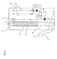
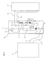
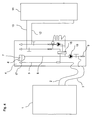
- FIG. 1 schematically shows a hydraulic interface 4 for connecting a combined heat and power plant 1, in particular a micro-combined heat and power plant such as a block heating (CHP), with a coolant circuit consisting of achenffenvorlauf- 2 and a coolant return line 3, in a building heating system with a memory 11.
- the hydraulic interface 4 is arranged between the coolant flow 2 and the coolant return 3 of the micro CHP plant 1 and the flow and return lines 13, 12 of the memory 11 of the heating system.
- a coolant tank 7 is arranged with a closure cover with pressure valve 8 for regulating resulting overpressure and underpressure.
- the flow line 2 is in the hydraulic interface in a coolant vent line 5, which may have a smaller cross-section than the flow line 2.
- a coolant line 6, which represents the transition of the return line 3 in the hydraulic interface the coolant is passed into the coolant tank 7.
- a heat exchanger 16 In the hydraulic interface 4, other hydraulic components such as e.g. a heat exchanger 16, a coolant pump 10 and a drain valve 9 are arranged, which are necessary for the heat extraction from the micro CHP plant 1 in the heating system.
- the storage 11 of the heating system contributes significantly to optimizing cogeneration performance when utilizing the combined heat and power plant, either as a sole heat source or in conjunction with a boiler for peak load coverage.
- the cooling water circuit of the micro CHP plant 1 can be filled and vented via the hydraulic interface 4, in which the coolant is vented into the coolant tank 7 via the coolant vent line 5 or coolant line 6 or filled.
- the coolant circuit can be emptied via the drain valve 9 in the hydraulic interface 4. This completes the filling and emptying of micro-CHP plants simplified. As such, the micro CHP system no longer needs to be opened for this purpose.
- the amount of evaporation in the coolant circuit is dependent on the maximum allowable pressure in the coolant circuit, the temperature of the coolant, the volume of air and the air temperature above the coolant level in the coolant tank. 7
- the regulation of the evaporation amount by the variation of the temperature in the coolant tank 7 by the device according to the invention represents a considerably inexpensive method.
- FIG. 1 shows a first device for reducing the amount of evaporation in the coolant circuit of the cogeneration plant.
- the coolant vent line 5 in this case represents a continuation of the feed line 2 and has a section to be cooled with preferably a smaller cross section.
- the section of the coolant vent line 5 to be cooled may be arranged in a meandering manner around a heat sink 14.
- the coolant flowing through the coolant vent line 5 to the coolant tank 7 releases its heat to the heat sink 14.
- the heat absorbed by the heat sink 14 is transported on to the environment.
- the environment may be either the housing interior of the hydraulic interface or a corresponding installation room.
- the heat sink 14 should be made of particularly good heat conducting materials such as copper.
- FIG. 2 The section of the coolant vent line 5 to be cooled is annular and ascending mounted on a metal tube 14.
- the metal tube 14 has at the bottom of the hydraulic interface 4 on a breakthrough, so that the cold air at this point from the bottom of the housing or the installation room can be sucked. This air is heated in the upper part of the metal pipe 14 by the heat release of the coolant ventilation pipe 5 and then flows out of the metal pipe 14. Due to the differences in density occurring natural convection in the pipe 14 is improved. Therefore, an optimized design of the tube 14 upstream of the heat transfer surface may have a reduction in area for air velocity and heat transfer enhancement.
- the metal tube 14 is made of a thermally conductive material and may be thermally connected to improve the heat dissipation with the housing of the hydraulic interface 4.
- the coolant flowing through the coolant vent line 5 and having the temperature of the lead 2 may be cooled with the return water from the heating system of the building. This is done before the heating water is heated in the downstream heat exchanger 16 by the coolant from the flow 2 of the combined heat and power plant 1. It is particularly advantageous in this arrangement of the section of the coolant vent line to be cooled, that the heat is not dissipated in the housing or in the installation room and the system is thereby additionally heated. The heat is transferred to the heating water and thus leads to an increase in the thermal efficiency of the combined heat and power plant.
- the section of the coolant ventilation line 5 to be cooled is arranged in a meandering manner around the return line 12 of the heating water.
- a double pipe construction or other types of heat exchangers could also be used.
- the coolant vent line 5 may be equipped with a blower. This may be an automatic venting device 17 in the coolant vent line 5, which blows the air to the outside with increasing amount of air. The coolant vent line 5 is then no longer connected to the coolant tank 7, whereby the temperature in the coolant tank 7 assumes the ambient temperature.
- a laying of the section of the coolant vent line 5 to be cooled outside the hydraulic interface 4 at a permanently low temperature point, e.g. in a ventilated space is also possible.
- FIG. 5 Another solution in FIG. 5 is the use of a thermostatic valve 15 in the coolant line 5, which closes with increasing temperature and at a set temperature (eg 40 ° C) is completely closed. As a result, the venting volume flow is reduced and the coolant temperature in the coolant reservoir 7 is limited.
- a thermostatic valve 15 in the coolant line 5 which closes with increasing temperature and at a set temperature (eg 40 ° C) is completely closed.
- a motor-operated control valve 15 can be used in the coolant vent line 5, which reduces the flow to the coolant tank 7 depending on the flow temperature and interrupts the flow at a defined temperature.
- the inventive arrangement evaporative losses are reduced by the coolant in the coolant tank 7, in which the coolant supplied via the coolant vent line 5 is cooled before the mouth in the coolant tank 7. Thus, the allowable pressure in the coolant tank is not exceeded.
- the reduction of the coolant evaporation amount in the coolant tank 7 takes place in a simple and cost-effective manner, as a result of which the coolant consumption and thus the service inserts for filling the coolant are considerably reduced.
Landscapes
- Engineering & Computer Science (AREA)
- Physics & Mathematics (AREA)
- Thermal Sciences (AREA)
- Chemical & Material Sciences (AREA)
- Combustion & Propulsion (AREA)
- Mechanical Engineering (AREA)
- General Engineering & Computer Science (AREA)
- Central Heating Systems (AREA)
Applications Claiming Priority (1)
| Application Number | Priority Date | Filing Date | Title |
|---|---|---|---|
| AT0101309A AT508486A3 (de) | 2009-06-30 | 2009-06-30 | Vorrichtung zur reduzierung der kühlmittelverdunstungsmenge im kühlmittelkreislauf einer kraft-wärme-kopplungsanlage |
Publications (2)
| Publication Number | Publication Date |
|---|---|
| EP2282130A2 true EP2282130A2 (fr) | 2011-02-09 |
| EP2282130A3 EP2282130A3 (fr) | 2015-11-25 |
Family
ID=42668489
Family Applications (1)
| Application Number | Title | Priority Date | Filing Date |
|---|---|---|---|
| EP10006376.7A Withdrawn EP2282130A3 (fr) | 2009-06-30 | 2010-06-19 | Dispositif de réduction de la quantité d'évaporation d'un moyen de refroidissement dans le circuit de refroidissement d'une installation de couplage force-chaleur |
Country Status (2)
| Country | Link |
|---|---|
| EP (1) | EP2282130A3 (fr) |
| AT (1) | AT508486A3 (fr) |
Family Cites Families (6)
| Publication number | Priority date | Publication date | Assignee | Title |
|---|---|---|---|---|
| US4593753A (en) * | 1984-11-09 | 1986-06-10 | Mcconnell Research Enterprises Pty. Ltd. | Exhaust gas liquid heating system for internal combustion engines |
| DE3816483A1 (de) * | 1988-05-13 | 1989-11-23 | Epi Ges Fuer Waermetechnik Und | Einheit aus einer verbrennungsmaschine und einem mit diesem gekoppelten generator |
| DE10207766A1 (de) * | 2002-02-23 | 2003-09-04 | Man Nutzfahrzeuge Ag | Kühlsystem eines Kraftfahrzeuges |
| US7284709B2 (en) * | 2003-11-07 | 2007-10-23 | Climate Energy, Llc | System and method for hydronic space heating with electrical power generation |
| SE529541C2 (sv) * | 2005-12-05 | 2007-09-11 | Volvo Lastvagnar Ab | Kylsystem |
| US20090151768A1 (en) * | 2007-12-18 | 2009-06-18 | Forseth David John | Heat tracing apparatus with heat-driven pumping system |
-
2009
- 2009-06-30 AT AT0101309A patent/AT508486A3/de not_active Application Discontinuation
-
2010
- 2010-06-19 EP EP10006376.7A patent/EP2282130A3/fr not_active Withdrawn
Non-Patent Citations (1)
| Title |
|---|
| None |
Also Published As
| Publication number | Publication date |
|---|---|
| AT508486A3 (de) | 2011-11-15 |
| AT508486A2 (de) | 2011-01-15 |
| EP2282130A3 (fr) | 2015-11-25 |
Similar Documents
| Publication | Publication Date | Title |
|---|---|---|
| EP2273203B1 (fr) | Installation de chauffage et/ou de préparation d'eau potable chaude | |
| DE102010056370A1 (de) | Vorrichtung zur Steigerung der Effizienz einer Wärmepumpe bei der Brauchwassererzeugung | |
| EP3027971B1 (fr) | Système de gestion de température | |
| EP3548743B1 (fr) | Dispositif de refroidissement servant au refroidissement d'une installation électrotechnique en mer | |
| DE19628818A1 (de) | Heizungsanlage | |
| CH623124A5 (en) | Method and device for carrying off surplus heat of a solar collector | |
| DE102009010493A1 (de) | Heizungsanlage für Gebäude | |
| DE2837540C2 (fr) | ||
| DE4432464C2 (de) | Verfahren und Anlage zum Erhitzen von Wasser mittels Dampf aus dem Dampfnetz einer Fernheizung | |
| EP1207355B1 (fr) | Installation centrale de chauffage et/ou de réfrigération pour au moins une bâtiment | |
| AT508486A2 (de) | Vorrichtung zur reduzierung der kühlmittelverdunstungsmenge im kühlmittelkreislauf einer kraft-wärme-kopplungsanlage | |
| DE202015006366U1 (de) | Trink- und Brauchwasserversorgungseinrichtung eines Gebäudes und Regulierventil hierfür | |
| EP3751204B1 (fr) | Système de chauffage et réservoir à eau chaude | |
| DE202013000593U1 (de) | Regelventil für Heizkörper | |
| DE102006009112A1 (de) | Vorrichtung zur Minderung der Stagnationsbelastung in thermischen Solaranlagen | |
| DE19534951C2 (de) | Kühlkreislauf | |
| DE102020127443A1 (de) | Klimatisierungsanlage für ein Gebäude | |
| DE102009048394A1 (de) | Kühlsystem für Brennstoffzellensysteme, Verfahren zum Kühlen von Brennstoffzellensystemen | |
| DE19539199C2 (de) | Wärmespeicher für Heizungs- und/oder Brauchwasseranlagen | |
| DE10360580B4 (de) | Wärmerückgewinnungsgerät mit Solarwärmetauscher | |
| DE102009056097B4 (de) | Anlage zum Ergänzen einer Heizanlage | |
| EP2436992B1 (fr) | Dispositif de stockage pour un système de chauffage | |
| AT501612B1 (de) | Verfahren zum betreiben einer warmwasserbereitungsanlage und warmwasserbereitungsanlage | |
| DE102023125712A1 (de) | Gebäude-Heizungs- und Lüftungssystem | |
| DE202009007493U1 (de) | Übergabestation für den gemeinsamen Anschluss von Solaranlagen und Brauchwasseranlagen an Speicher |
Legal Events
| Date | Code | Title | Description |
|---|---|---|---|
| PUAI | Public reference made under article 153(3) epc to a published international application that has entered the european phase |
Free format text: ORIGINAL CODE: 0009012 |
|
| AK | Designated contracting states |
Kind code of ref document: A2 Designated state(s): AL AT BE BG CH CY CZ DE DK EE ES FI FR GB GR HR HU IE IS IT LI LT LU LV MC MK MT NL NO PL PT RO SE SI SK SM TR |
|
| AX | Request for extension of the european patent |
Extension state: BA ME RS |
|
| PUAL | Search report despatched |
Free format text: ORIGINAL CODE: 0009013 |
|
| AK | Designated contracting states |
Kind code of ref document: A3 Designated state(s): AL AT BE BG CH CY CZ DE DK EE ES FI FR GB GR HR HU IE IS IT LI LT LU LV MC MK MT NL NO PL PT RO SE SI SK SM TR |
|
| AX | Request for extension of the european patent |
Extension state: BA ME RS |
|
| RIC1 | Information provided on ipc code assigned before grant |
Ipc: F24D 19/08 20060101ALI20151016BHEP Ipc: F01P 11/02 20060101ALI20151016BHEP Ipc: F24D 3/10 20060101ALI20151016BHEP Ipc: F24D 11/00 20060101AFI20151016BHEP |
|
| STAA | Information on the status of an ep patent application or granted ep patent |
Free format text: STATUS: THE APPLICATION IS DEEMED TO BE WITHDRAWN |
|
| 18D | Application deemed to be withdrawn |
Effective date: 20160526 |