EP2282135A2 - Ventilateur - Google Patents
Ventilateur Download PDFInfo
- Publication number
- EP2282135A2 EP2282135A2 EP10006318A EP10006318A EP2282135A2 EP 2282135 A2 EP2282135 A2 EP 2282135A2 EP 10006318 A EP10006318 A EP 10006318A EP 10006318 A EP10006318 A EP 10006318A EP 2282135 A2 EP2282135 A2 EP 2282135A2
- Authority
- EP
- European Patent Office
- Prior art keywords
- air
- cover
- flow
- fan according
- fan
- Prior art date
- Legal status (The legal status is an assumption and is not a legal conclusion. Google has not performed a legal analysis and makes no representation as to the accuracy of the status listed.)
- Granted
Links
- 238000011144 upstream manufacturing Methods 0.000 claims abstract description 9
- 230000000284 resting effect Effects 0.000 abstract 2
- 239000011521 glass Substances 0.000 abstract 1
- 230000009467 reduction Effects 0.000 description 4
- 230000002411 adverse Effects 0.000 description 3
- 239000002184 metal Substances 0.000 description 3
- 230000003247 decreasing effect Effects 0.000 description 2
- 238000010586 diagram Methods 0.000 description 2
- 238000001746 injection moulding Methods 0.000 description 2
- 238000004519 manufacturing process Methods 0.000 description 2
- 239000000463 material Substances 0.000 description 2
- 238000000034 method Methods 0.000 description 2
- 230000008569 process Effects 0.000 description 2
- 230000015572 biosynthetic process Effects 0.000 description 1
- 230000008859 change Effects 0.000 description 1
- 230000001419 dependent effect Effects 0.000 description 1
- 230000000694 effects Effects 0.000 description 1
- 230000006872 improvement Effects 0.000 description 1
- 238000007373 indentation Methods 0.000 description 1
- 230000003287 optical effect Effects 0.000 description 1
- 230000002093 peripheral effect Effects 0.000 description 1
- 238000002360 preparation method Methods 0.000 description 1
- 125000006850 spacer group Chemical group 0.000 description 1
- 230000003068 static effect Effects 0.000 description 1
- 230000008719 thickening Effects 0.000 description 1
- 238000009423 ventilation Methods 0.000 description 1
Images


Classifications
-
- F—MECHANICAL ENGINEERING; LIGHTING; HEATING; WEAPONS; BLASTING
- F24—HEATING; RANGES; VENTILATING
- F24F—AIR-CONDITIONING; AIR-HUMIDIFICATION; VENTILATION; USE OF AIR CURRENTS FOR SCREENING
- F24F7/00—Ventilation
- F24F7/007—Ventilation with forced flow
- F24F7/013—Ventilation with forced flow using wall or window fans, displacing air through the wall or window
-
- F—MECHANICAL ENGINEERING; LIGHTING; HEATING; WEAPONS; BLASTING
- F04—POSITIVE - DISPLACEMENT MACHINES FOR LIQUIDS; PUMPS FOR LIQUIDS OR ELASTIC FLUIDS
- F04D—NON-POSITIVE-DISPLACEMENT PUMPS
- F04D19/00—Axial-flow pumps
- F04D19/002—Axial flow fans
-
- F—MECHANICAL ENGINEERING; LIGHTING; HEATING; WEAPONS; BLASTING
- F04—POSITIVE - DISPLACEMENT MACHINES FOR LIQUIDS; PUMPS FOR LIQUIDS OR ELASTIC FLUIDS
- F04D—NON-POSITIVE-DISPLACEMENT PUMPS
- F04D25/00—Pumping installations or systems
- F04D25/02—Units comprising pumps and their driving means
- F04D25/08—Units comprising pumps and their driving means the working fluid being air, e.g. for ventilation
- F04D25/12—Units comprising pumps and their driving means the working fluid being air, e.g. for ventilation the unit being adapted for mounting in apertures
-
- F—MECHANICAL ENGINEERING; LIGHTING; HEATING; WEAPONS; BLASTING
- F04—POSITIVE - DISPLACEMENT MACHINES FOR LIQUIDS; PUMPS FOR LIQUIDS OR ELASTIC FLUIDS
- F04D—NON-POSITIVE-DISPLACEMENT PUMPS
- F04D29/00—Details, component parts, or accessories
- F04D29/40—Casings; Connections of working fluid
- F04D29/52—Casings; Connections of working fluid for axial pumps
- F04D29/54—Fluid-guiding means, e.g. diffusers
- F04D29/541—Specially adapted for elastic fluid pumps
-
- F—MECHANICAL ENGINEERING; LIGHTING; HEATING; WEAPONS; BLASTING
- F04—POSITIVE - DISPLACEMENT MACHINES FOR LIQUIDS; PUMPS FOR LIQUIDS OR ELASTIC FLUIDS
- F04D—NON-POSITIVE-DISPLACEMENT PUMPS
- F04D29/00—Details, component parts, or accessories
- F04D29/70—Suction grids; Strainers; Dust separation; Cleaning
- F04D29/701—Suction grids; Strainers; Dust separation; Cleaning especially adapted for elastic fluid pumps
- F04D29/703—Suction grids; Strainers; Dust separation; Cleaning especially adapted for elastic fluid pumps specially for fans, e.g. fan guards
-
- F—MECHANICAL ENGINEERING; LIGHTING; HEATING; WEAPONS; BLASTING
- F24—HEATING; RANGES; VENTILATING
- F24F—AIR-CONDITIONING; AIR-HUMIDIFICATION; VENTILATION; USE OF AIR CURRENTS FOR SCREENING
- F24F13/00—Details common to, or for air-conditioning, air-humidification, ventilation or use of air currents for screening
- F24F13/08—Air-flow control members, e.g. louvres, grilles, flaps or guide plates
- F24F13/082—Grilles, registers or guards
Definitions
- the invention relates to a fan with at least one impeller having an axis of rotation and at least one suction channel with upstream of the impeller air intake or at least one blast duct with downstream of the impeller air outlet, to which - to form a lateral air inflow or outflow - by far a cover is arranged.
- Fans of the type mentioned are known from the prior art. They are often used in ventilation systems to supply air to or out of an environment. For example, exhaust air can be conveyed out of the environment by means of the fan or fresh air can be introduced into the environment.
- the fan has for this purpose an impeller, which is driven for example by an electric motor. By means of this impeller, an air flow through the fan is generated.
- the fan is in an exhaust air version, it has the at least one suction channel with air intake opening lying upstream of the impeller, with the cover being arranged at a distance from the air intake opening-to form the lateral air inflow.
- the fan may also be present as a supply air version.
- a blower channel is provided, which essentially corresponds to the suction channel except for the flow direction.
- the mentioned air inflow is in this case an air outflow.
- the cover is not only intended for the formation of the lateral air flow, but at the same time forms an optical cover of the fan or the air intake or the air outlet.
- the known fans have a strong pressure loss, which depends on an air flow rate, which passes through the fan depending.
- the efficiency designates the ratio of the air output (that is to say the quantity of delivered air) to the energy supplied to the fan.
- a fan with the features of claim 1. It is provided that in a zone between the back of the cover and the impeller at least one air guide is arranged, which reduces or suppresses an air flow around the axis of rotation. As a result of the impeller rotating during operation of the fan, an air vortex corresponding to the direction of rotation of the impeller is induced in the suction or blast duct.
- the air guiding means has a fixed axial extent. It is therefore not just for supporting one more element - for example, a filter - but rather suitable for guiding the flow of air flowing through the fan.
- the air flow is reduced or prevented around the axis of rotation, that is, in the region of the air guide or downstream of this, the occurrence of the air vortex induced by the impeller is at least partially prevented.
- the air flow around the rotation axis is reduced or prevented not only in the region of the air conduction, but also around an imaginary extension of the axis of rotation. Depending on whether the exhaust air version or the supply air version of the fan is present, this may be located upstream or downstream of the air guide.
- the characteristic of a fan is usually described by three areas.
- a stable area also referred to as a work area
- a strictly unstable area and a simply unstable area.
- the strictly unstable range lies between the simply unstable (low volume flow) and the stable range (high flow rate).
- the strictly unstable region of the characteristic curve is determined by a more or less pronounced (mathematical) saddle point. This should generally be reduced in its expression to a minimum.
- the arrangement of the cover in front of the air intake opening increases the strictly unstable area first. With help However, the Heilleitffens it can be reduced or even completely eliminated.
- the acoustic behavior of the fan is significantly improved, so that in comparison to known products a quieter operation is possible.
- a filter can be arranged on the air-guiding means or be supported on it.
- the air-guiding means has an air-guiding function and does not merely serve to arrange the filter in this area. It should be reduced or prevented air vortex between the air guide and the cover.
- the cover is assigned to the fan, but does not have to be attached directly to this. It can be provided, for example, to install the fan in a wall and to secure the cover not on the fan itself or a housing of the fan, but on the wall.
- the cover is preferably a closed cover, so it is impermeable to air. The air flowing through the fan can therefore pass only laterally from the cover to this.
- the air guiding means has at least one air guide web and / or a flow guide arranged on the rear side of the cover.
- the air duct is designed such that it opposes the flow of air present in the fan as low as possible a flow resistance, but at the same time exerts a guiding effect on the air flow.
- it has the smallest possible cross section perpendicular to a flow direction of the air flow, while it has a pronounced extent in the axial direction or air flow direction.
- the Lucasleitsteg can enforce the entire air guide or be formed only in one area. In the latter case, a plurality of air guide webs are preferably provided, which run, for example, parallel to one another. Alternatively or additionally, the flow guide is provided or formed there on the back of the cover.
- the air guiding means provides at least one retaining web which supports the air guiding web.
- the holding web can be present downstream, upstream or - based on the flow - at the same axial position.
- the retaining web serves, in particular, to stiffen the air guiding means by supporting the air guiding web.
- the retaining web can be connected to the Luftleitsteg, in particular attached to this.
- Also possible is a one-piece design of retaining bar and Heilleitsteg.
- the holding web may have the same or at least a similar axial extent as the air guide.
- the holding web can, for example, run at an angle to the air guide web. For example, while a 90 ° angle is provided, the holding web is thus perpendicular to the Heilleitsteg.
- the holding web can serve as well as the air guide for guiding the air flow.
- a development of the invention provides that shipsleitsteg and / or retaining web are held in a frame.
- the frame may be fastened in the zone, for example interchangeably.
- a locking device may be provided to remove the air guide or the frame of the air guide in a simple manner from the fan or to replace the air guide.
- a positive connection with a housing of the fan is provided on at least one side of the frame, while on the opposite side, the locking element is arranged. In this way, after opening the locking means, the frame can be folded out of the housing of the fan and then removed.
- the air guide web and / or the retaining web extends at least in regions straight, oblique, arcuate, star-shaped or meandering.
- the course of the air guide bar or of the holding bar can be chosen as desired.
- the air guide bar or holding web can be designed to be continuous in the aforementioned ways.
- the Luftleitsteg or holding web extends in regions straight and curved, for example, in at least one other area.
- Arcuate means that there is a curvature or a curve.
- a straight course may mean that the air guide or holding web, at least to areas of the frame, should it be provided, run parallel.
- the oblique or star-shaped Implementation feasible feasible.
- the courses described can therefore also be present when the respective web is inclined in the axial direction or is profiled.
- a development of the invention provides that the Lucasleitsteg and / or the retaining web are profiled. This means that they have at least partially - seen in cross section - a flow guide.
- the Strömungsleitprofils the flow characteristics of the air flow can be more selectively influenced than would be possible with a non-profiled design.
- Under Strömungsleitprofil can be understood, for example, a wing profile, so specially shaped airfoils that affect the air flow targeted.
- a development of the invention provides that the Lucasleitsteg and / or the retaining bar open into a support element.
- the support member may be provided.
- the support element is provided centrally, for example, on the air-guiding means, so that the air-conducting web or the retaining web open at least on one side into this.
- the support element can in principle be shaped arbitrarily. For example, it may have a rectangular cross-section.
- the flow-guiding means has at least one flow guide web and / or a flow guide structure formed at least in regions on the back of the cover.
- the flow guide designates an element which has at least one free surface, which faces away from the back of the cover in particular.
- the Strömungsleitsteg has in its longitudinal direction on the largest extent, while the height of the Strömungsleitstegs is less than or equal to the distance between the back of the cover and a housing of the fan.
- the flow guide webs advantageously have a smaller height than this distance.
- the Strömungsleitstege form on the back of the cover Strömungsleitkanäle. In these flow channels there is a guide of the air flow passing through the fan.
- the back of the cover may have elements which provide additional guidance of the flow.
- the back of the cover may have elements which provide additional guidance of the flow.
- a flow resistance which is applied from the back to the air flow, is reduced.
- the Strömungsleitsteg is a flow guide rib or a row of pins.
- the flow guide rib is essentially characterized in that it is not, like the row of pins, composed of many individual elements, ie pins. Rather, a substantially continuous course of the flow guide rib is provided. This does not mean, however, that the flow guide rib has to be continuous.
- the row of pins on the other hand, is composed of many individual, essentially pin-shaped elements, which are directly next to one another or spaced from each other and thus form the Strömungsleitsteg in their entirety.
- a combination of flow guide rib and pin row is possible. In this case, a flow guide rib is provided and overlaid by the row of pins, so that thickening of the wall thickness of the flow guide rib results at the flow guide rib, for example at intervals.
- the Strömungsleitsteg has a constant or a, in particular continuously, increasing height.
- the variable height there may also be a decreasing height.
- the flow guide web is arranged, for example, in the radial direction, then the height of the flow guide web can be provided to grow radially inwards.
- a continuous growth is advantageous.
- a sudden increase in altitude or a waveform-based slope is also possible.
- the Strömungsleitsteg has a straight or a curved course. Such a course, in turn, must be available only in certain areas.
- the flow guide must therefore not run consistently straight or curved.
- the curved course can be provided, for example, to impart to the air flow a twist which is opposite to the swirl of the air flow around the axis of rotation which is induced by the impeller. With a suitable adjustment of the curvature, then, at least for predetermined mass flows, a complete compensation of the twist can be achieved, and thus the air flow around the axis of rotation around prevented become.
- this goal can also be achieved by means of the straight course of the Strömungsleitstegs, in which case the geometry of the Strömungsleitstegs must be adapted to the air flow induced by the impeller around the axis of rotation around.
- the flow guide is continuous or partially interrupted.
- the flow guide rib runs continuously.
- it is subdivided into areas which may each have the same or a different length.
- it may also be advantageous to choose the length of the regions depending on a position of the region. For example, in a radially outwardly extending flow guide rib in an inner region, regions having a shorter length and in an outer region having a greater length may be provided. The increase in length can be continuous. The distance between the regions may remain constant or have a growing or falling length.
- the Strömungsleitsteg has at least one air passage. Under air passage is generally a recess to understand. This can be a bore, but also only a concavity or notch of Strömungsleitstegs. Such a design of the Strömungsleitstegs is acoustically advantageous.
- a surface of the Strömungsleitstegs be provided with a structure. This means that the height of the Strömungsleitstegs is locally varied by means of the air outlets.
- a development of the invention provides that the Strömungsleitsteg is profiled at least partially. He has so at least partially a flow guide.
- the term "Strömungsleitprofil” or “profiled” has already been defined above with reference to the Lucasleitstegs or the holding web.
- the flow guiding structure has dimples, riblets and / or winglets.
- the dimples create a golf ball-like structure. So there are spherical segment-shaped out and / or indentations on the back of the cover.
- the riblets form a groove and / or scale structure.
- the winglets serve primarily to induce further vortex structures, which either reduce flow resistance or counteract the impeller induced air flow around the axis of rotation.
- the riblets may for example be designed such that a free, pointing away from the back end tapers.
- a development of the invention provides a plurality Strömungsleitstege, which are arranged staggered at least at one end thereof to each other. This means that the end of a Strömungsleitstegs opposite the end of another Strömungsleitstegs is advanced or falls back.
- staggering in the radial direction may be provided. In this way it is prevented that the flow-through cross-section is blocked by the Strömungsleitstegen, which is particularly the case when all radially extending Strömungsleitstege to a center of the back of the cover to run. Nevertheless, such an arrangement may be advantageous and realized in a design of the fan.
- a development of the invention provides that at least one, in particular circular in plan view, free space is provided on the back of the cover, in which no Strömungsleitsteg and / or no Strömungsleitmila is provided.
- the free space is provided. This can in principle have any geometry, for example, it is circular.
- the Strömungsleitstege may end at least partially outside of the free space, in addition or alternatively, no Strömungsleit fabricat is provided in the free space as well.
- the free space can for example be arranged centrally on the back of the cover.
- the cover - in plan view - is rectangular, in particular square, round or oval.
- the cover can have any shape.
- the shape of the cover is tuned to a shape of the housing of the fan.
- the cover - in plan view - completely cover other areas of the fan, so have at least the same size or be larger.
- a smaller cover can be realized.
- the air guide is attached to a housing of the fan, in particular interchangeable.
- the frame of the air guiding means is provided, on which the air guiding web and / or holding web are arranged.
- the air-guiding means is exchangeable.
- the air guiding means may also be fixed without frame to the housing of the fan.
- it is intended to form the guide bar and / or the holding web in one piece with the housing.
- a spacer may be provided between the housing and air guide, in particular to the latter spaced from the impeller and the back of the cover to be arranged.
- a development of the invention provides that the air guide and / or the cover are integrally formed.
- the air-conducting means or the cover can be produced in a particularly simple and cost-effective manner if they are manufactured from one piece, that is to say no assembly operation is necessary after production.
- the air guiding means and / or the cover at least partially made of plastic and / or metal.
- the air guiding means may consist of sheet metal, in particular the air guide webs or retaining webs may be formed from sheet metal strips.
- other suitable materials for the preparation of the air-guiding means and / or the cover can be used.
- the air-guiding means and / or the cover be present as a molded part or as a formed part. This means that they are manufactured by injection molding or by forming.
- the injection molding process can be a or a multi-component process.
- the forming is realized for example with a deep-drawing process.
- the air guiding means and / or the cover can also be composed of individual parts.
- the impeller is part of an axial, radial or diagonal air conveyor.
- the air conveyor is a turbomachine, which serves in the sense of the fan to generate the air flow through the fan. Due to its rotational movement, the impeller causes the air flow around the axis of rotation, which is to be reduced or prevented by means of the measures explained above.
- the diagonal air conveyor here corresponds to a semi-radial air conveyor.
- a development of the invention provides that a stator is provided downstream or upstream of the impeller.
- the stator is provided, which is arranged in particular immediately adjacent to the impeller.
- the upstream arrangement of the air flow flows through the stator to the impeller, while in the downstream arrangement, the air is first conveyed through the impeller and then flows through the stator.
- a development of the invention provides that a use in an outdoor area or an interior area is provided.
- the fan described above is suitable for both indoor and outdoor use. In this case, only the materials from which the fan or its components are made to be matched to the site.
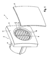
- the FIG. 1 shows a fan 1 with a housing 2 to which a cover 3 can be fastened.
- the cover 3 is substantially rectangular, in particular square, and is adapted to the shape of the housing 2. It is provided that the cover 3, the housing 2 protrudes slightly laterally. Alternatively, however, it can also be provided that the cover - in plan view - is just as large or even smaller than the housing.
- the cover 3 is detachably attached to the housing 2. This can be provided, for example, by means of a plug-in device, so that the cover 3 can be easily attached to the housing 2 and removed again, but no unintentional removal or falling off of the cover 3 from the housing 2 is possible.
- the housing 2 consists of a housing body 4 and a housing cover 5, wherein the housing cover 5 is held by means of locking means removably attached to the housing body 4.
- an air intake opening 6 is present in the housing cover 5.
- an air guiding means 7 can be seen, which consists of a frame 8, a holding web 9 and a plurality of air guide webs 10.
- a surface 11 of the housing cover 5 is - in cross-section - convex, wherein the cover 3 in its shape forms a corresponding counterpart, so - in cross-section - is also convex. This results in a spherically shaped recess in the housing cover 5 and the cover. 3
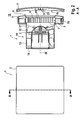
- FIG. 2 shows a front view of the fan 1, wherein initially the cover 3 can be seen.
- a sectional view is reproduced, in which a cross section (marked on the cover 3) of the fan 1 is shown.
- This cross-sectional illustration shows that in the fan 1 and in the housing 2, an impeller 12 and a stator 13 are arranged, which are part of an air conveyor 14. This serves to suck in air from an environment 15 of the fan 1 and to convey in the direction of an outlet 16.
- the air conveying device 14 is arranged in a suction channel 17 fluidically connected to the outlet 16.
- the air intake opening 6 is in this case - the exhaust version of the fan 1 - provided downstream of the impeller 12.
- the cover 3 is again spaced from the air intake opening 6 and the housing 2 and thus arranged by the housing cover 5.
- the air guiding means 7 is arranged in a zone 18, between a rear side 19 of the cover 3 and the impeller 12 of the air conveyor 14, the air guiding means 7 is arranged.
- the holding web 9, which extends from top to bottom or perpendicular thereto arranged shipsleitstege 10 and the frame 8.
- the air guide 7 has a certain extent in the axial direction (with respect to a rotation axis 20). Thus, it is suitable for guiding an air flow passing through the air conveyor 14 is generated. Due to the axial extent of the air guide 7, this serves to reduce or completely prevent an air flow around the axis of rotation 20 around.
- a further air-guiding means 7 'in the form of a flow-guiding means 21 is provided on the rear side 19 of the cover 3.
- the rear side 19 is at least partially provided with a flow guiding structure (not shown).
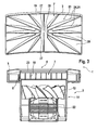
- FIG. 3 shows a cross-sectional view of the housing 2 of the fan 1.
- the cover 3 is shown explosionsdar suedsartig, the back 19 is visible.
- the FIG. 3 also shows that the impeller 12 is driven by means of an electric motor 22.
- a rim 23 of the air intake opening 6 formed in the housing cover 5 is arcuate in cross-section in the direction of the air delivery device 14. In this way it is avoided that there are sharp-edged areas in the flow path, which could adversely affect the acoustics of the fan 1.
- the flow-guiding means 21 formed on the rear side 19 of the cover 3 has a plurality of flow-guiding webs 24, each of which is in the form of a flow-guiding rib 25.
- a free space 26 is provided with a circular cross-section.
- none of the flow guide ribs 25 is present, these thus end outside the free space 26. In this case, they are arranged with their ends 27 staggered relative to one another.
- the flow guide ribs 25, which at an angle of a multiple are arranged at 45 °, directly adjacent to the free space 26, while further Strömungsleitrippen 25 are radially spaced from the free space 26.
- the angle given here is to be understood as purely exemplary. Needless to say, other angles, not mentioned here, of the flow guide ribs 25 are also possible. Likewise, it may be useful for some applications, not to provide a free space 26, but to guide the Strömungsleitrippen 25 to the center of the cover 3.
- the cover 3 is integrally formed.
- the flow guide ribs 25 are therefore already present immediately after the cover 3 has been produced.
- the cover 3 is produced as a molded part.
- the Strömungsleitrippen 25 thereby take a leadership of the air flow.
- the Strömungsleitrippen 25 are formed such that they have a comparatively large height in the region of the free space 26, which drops radially outward. This dropping takes place continuously, so that a linear change in the height of the flow guide ribs 25 or the flow guide webs 24 is provided.
- the flow guide ribs 25 extend in a straight line starting from the free space 26 radially outward.
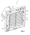
- FIG. 4 shows an isometric view of the fan 1, wherein the cover 3 and the housing cover 5 have been removed. Shown is therefore the housing body 4, to which the air guide 7 is removably attached with its frame 8. To this end On the one hand, rear grip elements 29 and the opposite side of the frame 8 locking elements 30 are provided.
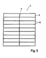
- the FIG. 5 shows a first embodiment of the air guide 7 in a plan view.
- the air guiding means 7 comprises the peripheral frame 8, in which both the holding web 9 and a plurality of air guide webs 10 are fastened.
- the air guide webs 10 are perpendicular to the support web 9 and extend substantially parallel to each other. Both the retaining web 9 and the Heilleitstege 10 are just arranged in the frame 8.
- the air guide 7 is formed in one piece and is made for example as a molded part made of plastic.
- the holding web 9 is provided on the air guiding means 7 in order to support the air guiding webs 10 over their longitudinal extension and thus in particular to prevent them from being excited to vibrations, which could adversely affect the acoustic behavior of the ventilator 1.
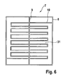
- FIG. 6 shows a second embodiment of the Lucasleitschs 7.
- the frame 8 and the holding web 9 is also provided, but there is only one Dunleitsteg 10, which extends meandering over a flow area 31 of the air guide 7. Loops of the meandering Heilleitstegs 10 may be at a constant distance or - as in the present embodiment - with varying distance.
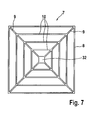
- FIG. 7 shows a third embodiment of the Lucasleitschs 7.
- two holding webs 9 and a plurality Dunleitstege 10 disposed in the frame 8.
- a support member 32 Centrally in the air guide 7, a support member 32 is provided. This has a substantially rectangular Cross-section on.
- the holding webs 9 open with one of its ends, while the other is held on the frame 8.
- the holding webs 9 are present in a star shape in the air guiding means 7, while the air guiding webs 10, viewed in cross section, enclose rectangles with a different surface.
- FIG. 8 shows the back 19 of the cover 3 in plan view. Visible here is again the free space 26, which is arranged centrally on the rear side 19 and has a circular cross-section, and the Strömungsleitrippen 25, which extend from the free space 26 in a star-shaped radially outward to an edge 33 of the cover 3.
- a surface 34 of the rear side 19 is provided with a flow guiding structure (not shown).
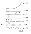
- FIG. 9 shows several embodiments of the Strömungsleitsteg 24 in plan view.
- a curved course is shown with a constant width, wherein the flow guide bar 24 is formed as a flow guide rib 25.
- a flow guide web 24 or a flow guide rib 25 which runs straight but has lateral recesses 35 with a substantially semicircular cross section, with which the cross section of the flow guide rib 25 varies over its length.
- the next embodiment of the Strömungsleitstegs 24 is composed of a thin flow guide rib 25 and a superimposed pin row 36 together.
- the row of pins 36 consists of equally spaced pins 37 whose diameter is greater than the width of the Strömungsleitrippe 25.
- the fourth embodiment of the Strömungsleitstegs 24 is a straight running Flow guide rib 25.
- a flow guide 25 is not continuous, but is partially interrupted.
- the flow guide rib 25 is subdivided into regions 38 ', 38 ", 38"' and so forth, the region 38 'being of short length and the subsequent elements (inter alia the regions 38 "and 38"') each having a greater length have, as the previous area.
- the distances between the regions 38 ', 38 ", 38"' and so on remain constant over the entire length of the flow guide rib 25.
- the next embodiment of the Strömungsleitstegs 24 is a row of pins 36, which, as already stated, consists of several pins 37.
- the row of pins 36 shown here consists of pins 37 each having a constant cross-section or diameter, each having the same distance from adjacent pins 37.
- the last embodiment of the Strömungsleitstegs 24 forms a Strömungsleitrippe 25, which has a constant cross section and a curved course. Curved does not mean that the curvature shows only in one direction, but this term summarizes all curved sections that are at least partially curved or curved.
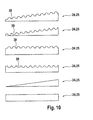
- FIG. 10 shows several examples of Strömungsleitstege 24 in a side view. It is clarified here that the flow guide webs 24 designed as flow guide ribs 25 can have both a constant (third, fourth and sixth embodiment) and an increasing or decreasing height (first, second and fifth embodiment).
- the Strömungsleitrippen 25 of the first four embodiments have air outlets 39, which substantially a local reduction in the height of the Flow guide 25 mean. Air can flow through the air outlets 39, which significantly improves the acoustic behavior of the fan 1.
- the FIG. 11 shows a graph for the pressure increase ⁇ p over the flow.
- characteristic curves 40 and 41 for a conventional (characteristic 40) and provided in accordance with the above (characteristic curve 41) fan 1 are shown.
- the characteristic curve 40 can be roughly divided into three regions, namely a simply unstable region 42, which is present for flow rates from 0 m 3 / h to about 15 m 3 / h, a strictly unstable region 43 (about 15 m 3 / h to about 40 m 3 / h) and a stable region 44 (greater than about 40 m 3 / h).
- the strictly unstable region 43 there is a saddle point 45.
- the characteristic curves 40 and 41 are nearly congruent.
- the strictly unstable region 43 and the simply unstable region 42 the pressure increase at the same volume flow for the characteristic curve 40 is significantly lower than for the characteristic curve 41.
- the strictly unstable region 43 which is clearly pronounced for the characteristic curve 40, has a Fan 1, as described above, largely avoided.
- the fan 1 can achieve a significantly greater pressure increase.
Landscapes
- Engineering & Computer Science (AREA)
- Mechanical Engineering (AREA)
- General Engineering & Computer Science (AREA)
- Chemical & Material Sciences (AREA)
- Combustion & Propulsion (AREA)
- Structures Of Non-Positive Displacement Pumps (AREA)
Applications Claiming Priority (1)
| Application Number | Priority Date | Filing Date | Title |
|---|---|---|---|
| DE102009032207.8A DE102009032207B4 (de) | 2009-07-03 | 2009-07-03 | Ventilator |
Publications (3)
| Publication Number | Publication Date |
|---|---|
| EP2282135A2 true EP2282135A2 (fr) | 2011-02-09 |
| EP2282135A3 EP2282135A3 (fr) | 2018-03-28 |
| EP2282135B1 EP2282135B1 (fr) | 2020-04-01 |
Family
ID=42829463
Family Applications (1)
| Application Number | Title | Priority Date | Filing Date |
|---|---|---|---|
| EP10006318.9A Active EP2282135B1 (fr) | 2009-07-03 | 2010-06-18 | Ventilateur |
Country Status (3)
| Country | Link |
|---|---|
| EP (1) | EP2282135B1 (fr) |
| DE (1) | DE102009032207B4 (fr) |
| ES (1) | ES2799401T3 (fr) |
Cited By (4)
| Publication number | Priority date | Publication date | Assignee | Title |
|---|---|---|---|---|
| GB2490138A (en) * | 2011-04-19 | 2012-10-24 | Rytons Building Products Ltd | Ventilation extraction grille |
| CN108679712A (zh) * | 2018-05-18 | 2018-10-19 | 青岛海尔空调器有限总公司 | 一种空调室内机及其控制方法 |
| DE102018203629B3 (de) | 2018-03-09 | 2019-06-27 | Maico Elektroapparate-Fabrik Gmbh | Ventilatoreinsatz zur Anordnung in einem Montagegehäuse, Ventilatoranordnung sowie Verfahren zum Montieren einer Ventilatoranordnung |
| EP4187102A1 (fr) * | 2021-11-25 | 2023-05-31 | MAICO Elektroapparate-Fabrik GmbH | Soupape de réglage, en particulier pour un dispositif de ventilation, procédé de fonctionnement d'une soupape de réglage ainsi que dispositif de ventilation doté d'une soupape de réglage |
Families Citing this family (5)
| Publication number | Priority date | Publication date | Assignee | Title |
|---|---|---|---|---|
| DE102011013015A1 (de) * | 2011-03-03 | 2012-09-06 | Jens Bader | Druckbelüfter zur Brandbekämpfung |
| DE202013104384U1 (de) * | 2013-09-26 | 2015-01-08 | Bärbel Burkhardt-Ganter | Vorrichtung zur Erzeugung von Luftströmungen, insbesondere Windmaschine für fotographische oder filmische Zwecke |
| DE102015115415A1 (de) * | 2015-09-14 | 2017-03-16 | Shuangliang Clyde Bergemann GmbH | Luftkühler mit Luftleitblechen |
| DE102021204015A1 (de) * | 2021-04-22 | 2022-10-27 | Maico Elektroapparate-Fabrik Gesellschaft mit beschränkter Haftung | Stellventil, insbesondere für eine Lüftungseinrichtung, Verfahren zum Betreiben eines Stellventils sowie Lüftungseinrichtung mit einem Stellventil |
| DE102022117314A1 (de) | 2022-07-12 | 2024-01-18 | Andreas Seibold | Vorrichtung zum austausch von wärmeenergie mit der umgebungsluft |
Family Cites Families (9)
| Publication number | Priority date | Publication date | Assignee | Title |
|---|---|---|---|---|
| GB583557A (en) * | 1944-10-26 | 1946-12-20 | Joseph Cuthbert Akester | Improvements in or relating to ventilating fan units |
| DE19925439B4 (de) * | 1999-06-02 | 2008-12-11 | Stego-Holding Gmbh | Lüfter |
| JP4108902B2 (ja) * | 2000-05-09 | 2008-06-25 | 東芝キヤリア株式会社 | 換気機器 |
| GB0328384D0 (en) * | 2003-12-06 | 2004-01-14 | Johnson Electric Sa | Blower motor |
| JP2007332818A (ja) * | 2006-06-13 | 2007-12-27 | Toshiaki Nakayama | 吸気側にガイド板を持つ換気装置 |
| DE202006009355U1 (de) * | 2006-06-13 | 2006-09-07 | Pfannenberg Gmbh | Filterlüfter mit einer Schnellbefestigungseinrichtung |
| ATE422619T1 (de) * | 2006-08-30 | 2009-02-15 | Ralf Meier | Strömungsgleichrichter für einen ventilator |
| DE102009004366A1 (de) * | 2009-01-08 | 2010-07-15 | Riegelhof & Gärtner oHG | Lüfter |
| US8070420B2 (en) * | 2009-05-28 | 2011-12-06 | Chen Yung-Hua | Airflow-cooling apparatus for a ceiling air-conditioning circulation machine |
-
2009
- 2009-07-03 DE DE102009032207.8A patent/DE102009032207B4/de active Active
-
2010
- 2010-06-18 EP EP10006318.9A patent/EP2282135B1/fr active Active
- 2010-06-18 ES ES10006318T patent/ES2799401T3/es active Active
Non-Patent Citations (1)
| Title |
|---|
| None |
Cited By (5)
| Publication number | Priority date | Publication date | Assignee | Title |
|---|---|---|---|---|
| GB2490138A (en) * | 2011-04-19 | 2012-10-24 | Rytons Building Products Ltd | Ventilation extraction grille |
| GB2490138B (en) * | 2011-04-19 | 2015-08-05 | Rytons Building Products Ltd | Ventilation extractor grille |
| DE102018203629B3 (de) | 2018-03-09 | 2019-06-27 | Maico Elektroapparate-Fabrik Gmbh | Ventilatoreinsatz zur Anordnung in einem Montagegehäuse, Ventilatoranordnung sowie Verfahren zum Montieren einer Ventilatoranordnung |
| CN108679712A (zh) * | 2018-05-18 | 2018-10-19 | 青岛海尔空调器有限总公司 | 一种空调室内机及其控制方法 |
| EP4187102A1 (fr) * | 2021-11-25 | 2023-05-31 | MAICO Elektroapparate-Fabrik GmbH | Soupape de réglage, en particulier pour un dispositif de ventilation, procédé de fonctionnement d'une soupape de réglage ainsi que dispositif de ventilation doté d'une soupape de réglage |
Also Published As
| Publication number | Publication date |
|---|---|
| ES2799401T3 (es) | 2020-12-17 |
| DE102009032207A1 (de) | 2011-01-05 |
| EP2282135B1 (fr) | 2020-04-01 |
| EP2282135A3 (fr) | 2018-03-28 |
| DE102009032207B4 (de) | 2016-11-17 |
Similar Documents
| Publication | Publication Date | Title |
|---|---|---|
| EP2282135B1 (fr) | Ventilateur | |
| DE60117177T2 (de) | Hocheffizienter, zustromangepasster axiallüfter | |
| EP2823184B1 (fr) | Ventilateur axial | |
| DE3137114C2 (fr) | ||
| EP3824190B1 (fr) | Ventilateur et équipement conducteur pour un ventilateur | |
| EP3255281B1 (fr) | Ventilateur avec aubes de diffuseur tandem | |
| EP2362065B1 (fr) | Canal de dérivation avec couronne d'aubes statoriques dans un turboréacteur avec soufflante | |
| DE2551614A1 (de) | Axial kurzer axialventilator | |
| EP2418389A2 (fr) | Hélice pour un ventilateur | |
| WO2018219414A2 (fr) | Ventilateur et grille de pré-guidage pour ventilateur | |
| EP2778432A1 (fr) | Redresseur de courant | |
| DE202014100752U1 (de) | Handgebläse | |
| EP2466150B1 (fr) | Procédé de fabrication d'une roue à pales pour un ventilateur | |
| EP0891519A2 (fr) | Procede et dispositif pour confiner, retenir et aspirer des fumees, des poussieres ou similaire | |
| EP2686609B1 (fr) | Dispositif de mélange pour mélanger de l'air de combustion et du gaz pour un appareil à gaz | |
| DE102018205300A1 (de) | Ventilator und Einströmgitter für einen Ventilator | |
| DE112013005410T5 (de) | Luftfilter mit Wirbel erzeugender Strömungsführung | |
| DE102018211809A1 (de) | Gehäuse für einen Ventilator und Ventilator | |
| EP3156642A1 (fr) | Installation d'energie d'ecoulement, en particulier eolienne | |
| DE69835588T2 (de) | Gebläse | |
| EP2915927B1 (fr) | Composant sanitaire | |
| EP2177769A2 (fr) | Boîtier pour soufflante radiale | |
| EP2700822A1 (fr) | Carter de ventilateur radial avec canal de mesure de pression intégré à la bouche d'aspiration | |
| EP2679803B1 (fr) | Pale de rotor d'éolienne dotée d'un bord de fuite à profil épais | |
| EP2222997A1 (fr) | Tube doté d'une partie d'extrémité de tube destinée à être raccordée à une tubulure de sortie d'air et tubulure de sortie d'air correspondante |
Legal Events
| Date | Code | Title | Description |
|---|---|---|---|
| PUAI | Public reference made under article 153(3) epc to a published international application that has entered the european phase |
Free format text: ORIGINAL CODE: 0009012 |
|
| AK | Designated contracting states |
Kind code of ref document: A2 Designated state(s): AL AT BE BG CH CY CZ DE DK EE ES FI FR GB GR HR HU IE IS IT LI LT LU LV MC MK MT NL NO PL PT RO SE SI SK SM TR |
|
| AX | Request for extension of the european patent |
Extension state: BA ME RS |
|
| RIN1 | Information on inventor provided before grant (corrected) |
Inventor name: PIETSCH, LARS Inventor name: STRICKER, KLAUS |
|
| PUAL | Search report despatched |
Free format text: ORIGINAL CODE: 0009013 |
|
| AK | Designated contracting states |
Kind code of ref document: A3 Designated state(s): AL AT BE BG CH CY CZ DE DK EE ES FI FR GB GR HR HU IE IS IT LI LT LU LV MC MK MT NL NO PL PT RO SE SI SK SM TR |
|
| AX | Request for extension of the european patent |
Extension state: BA ME RS |
|
| RIC1 | Information provided on ipc code assigned before grant |
Ipc: F04D 25/12 20060101ALI20180220BHEP Ipc: F24F 13/08 20060101ALI20180220BHEP Ipc: F24F 7/013 20060101AFI20180220BHEP Ipc: F04D 29/70 20060101ALI20180220BHEP |
|
| STAA | Information on the status of an ep patent application or granted ep patent |
Free format text: STATUS: REQUEST FOR EXAMINATION WAS MADE |
|
| 17P | Request for examination filed |
Effective date: 20180925 |
|
| RBV | Designated contracting states (corrected) |
Designated state(s): AL AT BE BG CH CY CZ DE DK EE ES FI FR GB GR HR HU IE IS IT LI LT LU LV MC MK MT NL NO PL PT RO SE SI SK SM TR |
|
| GRAP | Despatch of communication of intention to grant a patent |
Free format text: ORIGINAL CODE: EPIDOSNIGR1 |
|
| STAA | Information on the status of an ep patent application or granted ep patent |
Free format text: STATUS: GRANT OF PATENT IS INTENDED |
|
| RIC1 | Information provided on ipc code assigned before grant |
Ipc: F24F 7/013 20060101AFI20190918BHEP Ipc: F04D 29/70 20060101ALI20190918BHEP Ipc: F04D 25/12 20060101ALI20190918BHEP Ipc: F24F 13/08 20060101ALI20190918BHEP |
|
| INTG | Intention to grant announced |
Effective date: 20191021 |
|
| GRAS | Grant fee paid |
Free format text: ORIGINAL CODE: EPIDOSNIGR3 |
|
| GRAA | (expected) grant |
Free format text: ORIGINAL CODE: 0009210 |
|
| STAA | Information on the status of an ep patent application or granted ep patent |
Free format text: STATUS: THE PATENT HAS BEEN GRANTED |
|
| AK | Designated contracting states |
Kind code of ref document: B1 Designated state(s): AL AT BE BG CH CY CZ DE DK EE ES FI FR GB GR HR HU IE IS IT LI LT LU LV MC MK MT NL NO PL PT RO SE SI SK SM TR |
|
| REG | Reference to a national code |
Ref country code: GB Ref legal event code: FG4D Free format text: NOT ENGLISH |
|
| REG | Reference to a national code |
Ref country code: CH Ref legal event code: EP Ref country code: AT Ref legal event code: REF Ref document number: 1251840 Country of ref document: AT Kind code of ref document: T Effective date: 20200415 |
|
| REG | Reference to a national code |
Ref country code: DE Ref legal event code: R096 Ref document number: 502010016558 Country of ref document: DE |
|
| REG | Reference to a national code |
Ref country code: IE Ref legal event code: FG4D Free format text: LANGUAGE OF EP DOCUMENT: GERMAN |
|
| REG | Reference to a national code |
Ref country code: CH Ref legal event code: NV Representative=s name: OFFICE ERNEST T. FREYLINGER S.A., CH |
|
| PG25 | Lapsed in a contracting state [announced via postgrant information from national office to epo] |
Ref country code: BG Free format text: LAPSE BECAUSE OF FAILURE TO SUBMIT A TRANSLATION OF THE DESCRIPTION OR TO PAY THE FEE WITHIN THE PRESCRIBED TIME-LIMIT Effective date: 20200701 |
|
| REG | Reference to a national code |
Ref country code: NL Ref legal event code: MP Effective date: 20200401 |
|
| REG | Reference to a national code |
Ref country code: LT Ref legal event code: MG4D |
|
| PG25 | Lapsed in a contracting state [announced via postgrant information from national office to epo] |
Ref country code: SE Free format text: LAPSE BECAUSE OF FAILURE TO SUBMIT A TRANSLATION OF THE DESCRIPTION OR TO PAY THE FEE WITHIN THE PRESCRIBED TIME-LIMIT Effective date: 20200401 Ref country code: NL Free format text: LAPSE BECAUSE OF FAILURE TO SUBMIT A TRANSLATION OF THE DESCRIPTION OR TO PAY THE FEE WITHIN THE PRESCRIBED TIME-LIMIT Effective date: 20200401 Ref country code: LT Free format text: LAPSE BECAUSE OF FAILURE TO SUBMIT A TRANSLATION OF THE DESCRIPTION OR TO PAY THE FEE WITHIN THE PRESCRIBED TIME-LIMIT Effective date: 20200401 Ref country code: GR Free format text: LAPSE BECAUSE OF FAILURE TO SUBMIT A TRANSLATION OF THE DESCRIPTION OR TO PAY THE FEE WITHIN THE PRESCRIBED TIME-LIMIT Effective date: 20200702 Ref country code: NO Free format text: LAPSE BECAUSE OF FAILURE TO SUBMIT A TRANSLATION OF THE DESCRIPTION OR TO PAY THE FEE WITHIN THE PRESCRIBED TIME-LIMIT Effective date: 20200701 Ref country code: IS Free format text: LAPSE BECAUSE OF FAILURE TO SUBMIT A TRANSLATION OF THE DESCRIPTION OR TO PAY THE FEE WITHIN THE PRESCRIBED TIME-LIMIT Effective date: 20200801 Ref country code: PT Free format text: LAPSE BECAUSE OF FAILURE TO SUBMIT A TRANSLATION OF THE DESCRIPTION OR TO PAY THE FEE WITHIN THE PRESCRIBED TIME-LIMIT Effective date: 20200817 Ref country code: CZ Free format text: LAPSE BECAUSE OF FAILURE TO SUBMIT A TRANSLATION OF THE DESCRIPTION OR TO PAY THE FEE WITHIN THE PRESCRIBED TIME-LIMIT Effective date: 20200401 Ref country code: FI Free format text: LAPSE BECAUSE OF FAILURE TO SUBMIT A TRANSLATION OF THE DESCRIPTION OR TO PAY THE FEE WITHIN THE PRESCRIBED TIME-LIMIT Effective date: 20200401 |
|
| PG25 | Lapsed in a contracting state [announced via postgrant information from national office to epo] |
Ref country code: LV Free format text: LAPSE BECAUSE OF FAILURE TO SUBMIT A TRANSLATION OF THE DESCRIPTION OR TO PAY THE FEE WITHIN THE PRESCRIBED TIME-LIMIT Effective date: 20200401 Ref country code: HR Free format text: LAPSE BECAUSE OF FAILURE TO SUBMIT A TRANSLATION OF THE DESCRIPTION OR TO PAY THE FEE WITHIN THE PRESCRIBED TIME-LIMIT Effective date: 20200401 |
|
| REG | Reference to a national code |
Ref country code: ES Ref legal event code: FG2A Ref document number: 2799401 Country of ref document: ES Kind code of ref document: T3 Effective date: 20201217 |
|
| PG25 | Lapsed in a contracting state [announced via postgrant information from national office to epo] |
Ref country code: AL Free format text: LAPSE BECAUSE OF FAILURE TO SUBMIT A TRANSLATION OF THE DESCRIPTION OR TO PAY THE FEE WITHIN THE PRESCRIBED TIME-LIMIT Effective date: 20200401 |
|
| REG | Reference to a national code |
Ref country code: DE Ref legal event code: R097 Ref document number: 502010016558 Country of ref document: DE |
|
| PG25 | Lapsed in a contracting state [announced via postgrant information from national office to epo] |
Ref country code: RO Free format text: LAPSE BECAUSE OF FAILURE TO SUBMIT A TRANSLATION OF THE DESCRIPTION OR TO PAY THE FEE WITHIN THE PRESCRIBED TIME-LIMIT Effective date: 20200401 Ref country code: MC Free format text: LAPSE BECAUSE OF FAILURE TO SUBMIT A TRANSLATION OF THE DESCRIPTION OR TO PAY THE FEE WITHIN THE PRESCRIBED TIME-LIMIT Effective date: 20200401 Ref country code: DK Free format text: LAPSE BECAUSE OF FAILURE TO SUBMIT A TRANSLATION OF THE DESCRIPTION OR TO PAY THE FEE WITHIN THE PRESCRIBED TIME-LIMIT Effective date: 20200401 Ref country code: EE Free format text: LAPSE BECAUSE OF FAILURE TO SUBMIT A TRANSLATION OF THE DESCRIPTION OR TO PAY THE FEE WITHIN THE PRESCRIBED TIME-LIMIT Effective date: 20200401 Ref country code: SM Free format text: LAPSE BECAUSE OF FAILURE TO SUBMIT A TRANSLATION OF THE DESCRIPTION OR TO PAY THE FEE WITHIN THE PRESCRIBED TIME-LIMIT Effective date: 20200401 |
|
| PLBE | No opposition filed within time limit |
Free format text: ORIGINAL CODE: 0009261 |
|
| STAA | Information on the status of an ep patent application or granted ep patent |
Free format text: STATUS: NO OPPOSITION FILED WITHIN TIME LIMIT |
|
| PG25 | Lapsed in a contracting state [announced via postgrant information from national office to epo] |
Ref country code: PL Free format text: LAPSE BECAUSE OF FAILURE TO SUBMIT A TRANSLATION OF THE DESCRIPTION OR TO PAY THE FEE WITHIN THE PRESCRIBED TIME-LIMIT Effective date: 20200401 Ref country code: SK Free format text: LAPSE BECAUSE OF FAILURE TO SUBMIT A TRANSLATION OF THE DESCRIPTION OR TO PAY THE FEE WITHIN THE PRESCRIBED TIME-LIMIT Effective date: 20200401 |
|
| 26N | No opposition filed |
Effective date: 20210112 |
|
| PG25 | Lapsed in a contracting state [announced via postgrant information from national office to epo] |
Ref country code: LU Free format text: LAPSE BECAUSE OF NON-PAYMENT OF DUE FEES Effective date: 20200618 |
|
| REG | Reference to a national code |
Ref country code: BE Ref legal event code: MM Effective date: 20200630 |
|
| PG25 | Lapsed in a contracting state [announced via postgrant information from national office to epo] |
Ref country code: IE Free format text: LAPSE BECAUSE OF NON-PAYMENT OF DUE FEES Effective date: 20200618 Ref country code: FR Free format text: LAPSE BECAUSE OF NON-PAYMENT OF DUE FEES Effective date: 20200630 |
|
| PG25 | Lapsed in a contracting state [announced via postgrant information from national office to epo] |
Ref country code: BE Free format text: LAPSE BECAUSE OF NON-PAYMENT OF DUE FEES Effective date: 20200630 Ref country code: SI Free format text: LAPSE BECAUSE OF FAILURE TO SUBMIT A TRANSLATION OF THE DESCRIPTION OR TO PAY THE FEE WITHIN THE PRESCRIBED TIME-LIMIT Effective date: 20200401 |
|
| PGFP | Annual fee paid to national office [announced via postgrant information from national office to epo] |
Ref country code: GB Payment date: 20210625 Year of fee payment: 12 |
|
| PGFP | Annual fee paid to national office [announced via postgrant information from national office to epo] |
Ref country code: ES Payment date: 20210825 Year of fee payment: 12 |
|
| PG25 | Lapsed in a contracting state [announced via postgrant information from national office to epo] |
Ref country code: TR Free format text: LAPSE BECAUSE OF FAILURE TO SUBMIT A TRANSLATION OF THE DESCRIPTION OR TO PAY THE FEE WITHIN THE PRESCRIBED TIME-LIMIT Effective date: 20200401 Ref country code: MT Free format text: LAPSE BECAUSE OF FAILURE TO SUBMIT A TRANSLATION OF THE DESCRIPTION OR TO PAY THE FEE WITHIN THE PRESCRIBED TIME-LIMIT Effective date: 20200401 Ref country code: CY Free format text: LAPSE BECAUSE OF FAILURE TO SUBMIT A TRANSLATION OF THE DESCRIPTION OR TO PAY THE FEE WITHIN THE PRESCRIBED TIME-LIMIT Effective date: 20200401 |
|
| PG25 | Lapsed in a contracting state [announced via postgrant information from national office to epo] |
Ref country code: MK Free format text: LAPSE BECAUSE OF FAILURE TO SUBMIT A TRANSLATION OF THE DESCRIPTION OR TO PAY THE FEE WITHIN THE PRESCRIBED TIME-LIMIT Effective date: 20200401 |
|
| PGFP | Annual fee paid to national office [announced via postgrant information from national office to epo] |
Ref country code: IT Payment date: 20220624 Year of fee payment: 13 |
|
| PGFP | Annual fee paid to national office [announced via postgrant information from national office to epo] |
Ref country code: AT Payment date: 20220621 Year of fee payment: 13 |
|
| PGFP | Annual fee paid to national office [announced via postgrant information from national office to epo] |
Ref country code: DE Payment date: 20220628 Year of fee payment: 13 |
|
| PGFP | Annual fee paid to national office [announced via postgrant information from national office to epo] |
Ref country code: CH Payment date: 20220701 Year of fee payment: 13 |
|
| GBPC | Gb: european patent ceased through non-payment of renewal fee |
Effective date: 20220618 |
|
| PG25 | Lapsed in a contracting state [announced via postgrant information from national office to epo] |
Ref country code: GB Free format text: LAPSE BECAUSE OF NON-PAYMENT OF DUE FEES Effective date: 20220618 |
|
| REG | Reference to a national code |
Ref country code: ES Ref legal event code: FD2A Effective date: 20230804 |
|
| PG25 | Lapsed in a contracting state [announced via postgrant information from national office to epo] |
Ref country code: ES Free format text: LAPSE BECAUSE OF NON-PAYMENT OF DUE FEES Effective date: 20220619 |
|
| REG | Reference to a national code |
Ref country code: DE Ref legal event code: R119 Ref document number: 502010016558 Country of ref document: DE |
|
| REG | Reference to a national code |
Ref country code: CH Ref legal event code: PL |
|
| REG | Reference to a national code |
Ref country code: AT Ref legal event code: MM01 Ref document number: 1251840 Country of ref document: AT Kind code of ref document: T Effective date: 20230618 |
|
| PG25 | Lapsed in a contracting state [announced via postgrant information from national office to epo] |
Ref country code: AT Free format text: LAPSE BECAUSE OF NON-PAYMENT OF DUE FEES Effective date: 20230618 |
|
| PG25 | Lapsed in a contracting state [announced via postgrant information from national office to epo] |
Ref country code: DE Free format text: LAPSE BECAUSE OF NON-PAYMENT OF DUE FEES Effective date: 20240103 Ref country code: AT Free format text: LAPSE BECAUSE OF NON-PAYMENT OF DUE FEES Effective date: 20230618 Ref country code: CH Free format text: LAPSE BECAUSE OF NON-PAYMENT OF DUE FEES Effective date: 20230630 |
|
| PG25 | Lapsed in a contracting state [announced via postgrant information from national office to epo] |
Ref country code: IT Free format text: LAPSE BECAUSE OF NON-PAYMENT OF DUE FEES Effective date: 20230618 |