EP2282408A2 - Appareil d'émetteur-récepteur à multiplexage par répartition en fréquences, appareil d'émetteur-récepteur à multiplexage par réparation du nombre d'ondes et son procédé - Google Patents
Appareil d'émetteur-récepteur à multiplexage par répartition en fréquences, appareil d'émetteur-récepteur à multiplexage par réparation du nombre d'ondes et son procédé Download PDFInfo
- Publication number
- EP2282408A2 EP2282408A2 EP20100189317 EP10189317A EP2282408A2 EP 2282408 A2 EP2282408 A2 EP 2282408A2 EP 20100189317 EP20100189317 EP 20100189317 EP 10189317 A EP10189317 A EP 10189317A EP 2282408 A2 EP2282408 A2 EP 2282408A2
- Authority
- EP
- European Patent Office
- Prior art keywords
- symbol
- unit
- wave
- symbol sequence
- symbols
- Prior art date
- Legal status (The legal status is an assumption and is not a legal conclusion. Google has not performed a legal analysis and makes no representation as to the accuracy of the status listed.)
- Withdrawn
Links
Images









Classifications
-
- H—ELECTRICITY
- H04—ELECTRIC COMMUNICATION TECHNIQUE
- H04L—TRANSMISSION OF DIGITAL INFORMATION, e.g. TELEGRAPHIC COMMUNICATION
- H04L5/00—Arrangements affording multiple use of the transmission path
- H04L5/003—Arrangements for allocating sub-channels of the transmission path
- H04L5/0044—Allocation of payload; Allocation of data channels, e.g. PDSCH or PUSCH
-
- H—ELECTRICITY
- H04—ELECTRIC COMMUNICATION TECHNIQUE
- H04B—TRANSMISSION
- H04B1/00—Details of transmission systems, not covered by a single one of groups H04B3/00 - H04B13/00; Details of transmission systems not characterised by the medium used for transmission
- H04B1/69—Spread spectrum techniques
- H04B1/707—Spread spectrum techniques using direct sequence modulation
-
- H—ELECTRICITY
- H04—ELECTRIC COMMUNICATION TECHNIQUE
- H04L—TRANSMISSION OF DIGITAL INFORMATION, e.g. TELEGRAPHIC COMMUNICATION
- H04L27/00—Modulated-carrier systems
- H04L27/26—Systems using multi-frequency codes
- H04L27/2601—Multicarrier modulation systems
- H04L27/2626—Arrangements specific to the transmitter only
-
- H—ELECTRICITY
- H04—ELECTRIC COMMUNICATION TECHNIQUE
- H04L—TRANSMISSION OF DIGITAL INFORMATION, e.g. TELEGRAPHIC COMMUNICATION
- H04L5/00—Arrangements affording multiple use of the transmission path
- H04L5/003—Arrangements for allocating sub-channels of the transmission path
- H04L5/0037—Inter-user or inter-terminal allocation
-
- H—ELECTRICITY
- H04—ELECTRIC COMMUNICATION TECHNIQUE
- H04J—MULTIPLEX COMMUNICATION
- H04J13/00—Code division multiplex systems
- H04J13/0007—Code type
- H04J13/004—Orthogonal
- H04J13/0048—Walsh
-
- H—ELECTRICITY
- H04—ELECTRIC COMMUNICATION TECHNIQUE
- H04L—TRANSMISSION OF DIGITAL INFORMATION, e.g. TELEGRAPHIC COMMUNICATION
- H04L27/00—Modulated-carrier systems
- H04L27/26—Systems using multi-frequency codes
- H04L27/2601—Multicarrier modulation systems
- H04L27/2602—Signal structure
- H04L27/2605—Symbol extensions, e.g. Zero Tail, Unique Word [UW]
- H04L27/2607—Cyclic extensions
-
- H—ELECTRICITY
- H04—ELECTRIC COMMUNICATION TECHNIQUE
- H04L—TRANSMISSION OF DIGITAL INFORMATION, e.g. TELEGRAPHIC COMMUNICATION
- H04L5/00—Arrangements affording multiple use of the transmission path
- H04L5/0001—Arrangements for dividing the transmission path
- H04L5/0003—Two-dimensional division
-
- H—ELECTRICITY
- H04—ELECTRIC COMMUNICATION TECHNIQUE
- H04L—TRANSMISSION OF DIGITAL INFORMATION, e.g. TELEGRAPHIC COMMUNICATION
- H04L5/00—Arrangements affording multiple use of the transmission path
- H04L5/0001—Arrangements for dividing the transmission path
- H04L5/0003—Two-dimensional division
- H04L5/0005—Time-frequency
- H04L5/0007—Time-frequency the frequencies being orthogonal, e.g. OFDM(A) or DMT
Definitions
- This invention relates to a frequency-division multiplexing transceiver apparatus, wave-number-division multiplexing transceiver apparatus and method thereof, and more particularly to a frequency-division multiplexing transceiver apparatus, wave-number-division multiplexing transceiver apparatus and method for transmitting data in a frequency spectrum or wave-number spectrum.
- DS-CDMA Direct Sequence-Code Division Multiple Access multiplies a narrow-band transmission signal by a spreading code in order to spread and transmit that transmission signal over a wider band.
- DS-CDMA direct Sequence-Code Division Multiple Access
- the information transmission speed becomes 1/SF. Therefore, in order to achieve a frequency utilization efficiency that is equivalent to that of TDMA, it is necessary in DS-CDMA to accommodate a number of signals that is equal to SF number of mobile stations.
- MIMO Multiple Access Interference
- the effect of Multiple Access Interference (MAI) in which the signals from each of the mobile stations interfere with each other, becomes dominant due to differences in propagation conditions from each mobile station to the base station, for example, due to differences in propagation-delay time or propagation-path fluctuation, and thus the rate of frequency utilization decreases.
- IFDMA Interleaved Frequency Division Multiple Access
- next-generation mobile communications see the specification of JP2004-297756A , and Goto, et al.,"Investigations on Packet Error Rate of Variable Spreading and Chip Repetition Factors (VSCRF)-CDMA Wireless Access in Reverse Link Multi-cell Environment", The Institute of Electronics, Information and Communication Engineers, Technical Report of IEICE, RCS2004-84 (204-206 ).
- This IFDMA modulation method transmits a transmission signal upon multiplying the signal by a phase that changes at a speed specific to the mobile station, thereby reducing MAI by placing the signals from each of the mobile stations on a frequency axis in such a manner that the signals will not overlap each other on the frequency axis.
- Fig. 21 is a block diagram showing the structure of a mobile station that uses an IFDMA modulation method
- Fig. 22 is a drawing that explains an IFDMA symbol.
- a channel encoder 1a performs channel encoding by applying error-correction encoding such as turbo encoding or convolutional encoding to an entered binary information sequence
- a data modulator 1b converts the channel-encoded data to I,Q complex components (symbols). in QPSK, for example.
- Tc the sample period
- a phase-rotation unit 1d has a complex multiplier CML that performs mobile-station specific phase rotation for each symbol in the repetitive symbol sequence (see (c) of Fig. 22 ), and a wireless transmitter 1e performs up-conversion of the signal that is input from the phase-rotation unit 1d from baseband frequency to radio frequency, after which it amplifies the signal and transmits it from an antenna.
- phase-rotation unit 1d calculates I, Q components (x, y) in a complex plane of the rotation phase amount ⁇ and inputs these components to the phase-rotation unit 1d.
- the phase-rotation unit 1d performs a calculation according to the following equation and outputs the calculation result.
- X + jY ⁇ x + jy the complex multiplier CML of the phase-rotation unit 1d calculates and outputs (Xx - Yy) and (Xy + Yx) for each real-number and imaginary-number part.
- the present invention seeks to reduce multi-path interference without using a multi-path canceller.
- OFDM OFDM
- PAPR PAPR to become large due to multiplexing. Therefore, the present invention also seeks to prevent that PAPR from becoming large.
- a first form of the present invention is a frequency-division multiplexing transmission apparatus that transmits data in a frequency spectrum specific to both symbol and mobile station.
- a first frequency-division multiplexing transmission apparatus of the first form of the invention comprises: an encoder for encoding transmission data; a data-modulation unit for modulating output data from the encoder; a time-domain compression and repetition unit for compressing the time domains of each symbol of the transmission-symbol sequence that is output from the modulation unit, and repeating the symbols a specified number of times; a symbol-rearrangement unit for rearranging each of the symbols of the obtained repetitive-symbol sequence so that they have the same arrangement as the transmission-symbol sequence; a first phase-generation unit for generating each phase that respectively changes at a speed specific to each symbol of the transmission symbol sequence; a first phase-rotation unit for performing phase rotation specific to the symbols for each symbol of the rearranged repetitive-symbol sequence; a second phase-generation unit for generating phase that changes
- a second frequency-division multiplexing transmission apparatus of the first form of the present invention comprises: an encoder for encoding transmission data; a data-modulation unit for modulating output data from the encoder; a time-domain compression and repetition unit for compressing the time domains of each symbol of the transmission-symbol sequence that is output from the modulation unit, and repeating the symbols a specified number of times; a symbol-rearrangement unit for rearranging each of the symbols of the obtained repetitive-symbol sequence so that they have the same arrangement as the transmission-symbol sequence; a phase-generation unit for generating each phase that changes at a speed specific to each symbol of the transmission-symbol sequence and mobile station; a phase-rotation unit for performing phase rotation of the phase that is output from the phase-generation unit for each symbol of the rearranged repetitive-symbol sequence; and a transmission unit for transmitting the output from the phase-rotation unit.
- a third frequency-division multiplexing transmission apparatus of the first form of the present invention comprises: an encoder for encoding transmission data; a data-modulation unit for modulating output data from the encoder; a time-domain compression and repetition unit for compressing the time domains of each symbol of the transmission-symbol sequence that is output from the modulation unit, and repeating the symbols a specified number of times; a symbol-rearrangement unit for rearranging each of the symbols of the obtained repetitive-symbol sequence so that they have the same arrangement as the transmission-symbol sequence; a phase-generation unit for generating each phase that changes at a speed specific to each symbol of the transmission-symbol sequence; a phase-rotation unit for performing phase rotation specific to the symbols for each symbol of the rearranged repetitive-symbol sequence; and a transmission unit for transmitting the output from the phase-rotation unit.
- a frequency-division multiplexing receiving apparatus of this first form of the invention comprises: a receiving unit for receiving signals transmitted from the transmission apparatus; an orthogonal-demodulation unit for demodulating each of the symbols of the repetitive-symbol sequence from the received signal; a timing-detection unit for detecting the frame-symbol timing of the received symbol sequence; an FFT processing unit for selecting the received symbol sequence at the timing detected by the timing-detection unit, then performing FFT conversion of the received symbol sequence and converting it to a frequency spectrum; a combiner for combining the frequency spectra specific to the symbol of the transmission-symbol sequence and the mobile station for each mobile station and symbol; and a decoder for decoding data from the combined signal of each symbol.
- a second form of the present invention is a wave-number-division multiplexing transmission apparatus that transmits data in a wave-number spectrum specific to both symbol and mobile station.
- This wave-number-division multiplexing transmission apparatus comprises: an encoder for encoding transmission data; a data-modulation unit for modulating output data from the encoder; a time-domain compression and repetition unit for compressing the time domains of each symbol of the transmission-symbol sequence that is output from the modulation unit, and repeating the symbols a specified number of times; a symbol-rearrangement unit for rearranging each of the symbols of the obtained repetitive-symbol sequence so that they have the same arrangement as the transmission-symbol sequence; a spreading-code-generation unit for generating specified wave number code that makes up Walsh code as spreading code for each symbol of the repetitive-symbol sequence; a spreading unit for multiplying each symbol of the repetitive-symbol sequence with the spreading code to spread the symbols; and a transmission unit for transmitting the output
- a wave-number-division multiplexing receiving apparatus of this second form of the invention comprises: a receiving unit for receiving signals transmitted from the transmission apparatus; an orthogonal-demodulation unit for demodulating each of the symbols of the repetitive-symbol sequence from the received signal; a timing-detection unit for detecting frame-symbol timing of the received symbol sequence; a Walsh WFT processing unit for selecting the received symbol sequence at the timing detected by the timing-detection uni t, and performing Walsh WFT conversion of the received symbol sequence to convert it to a wave-number spectrum; a combiner for combining the wave-number spectra specific to the symbol of the transmission-symbol sequence and the mobile station for each mobile station and symbol; and a decoder for decoding the data from the combined signals of each symbol.
- a third form of the present invention is a frequency-division multiplexing transmission method and a wave-number-division multiplexing transmission method.
- the frequency-division multiplexing transmission method of this third form of the invention comprises steps of executing each part of the frequency-division multiplexing transmission apparatus described above.
- the wave-number-division multiplexing transmission method comprises steps of executing each part of the wave-number-division multiplexing transmission apparatus described above.
- Fig. 1 is a block diagram showing a frequency-division multiplexing transmission apparatus of a first embodiment of the invention.
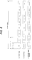
- Fig. 2 is a timing chart for explaining the operation of the frequency-division multiplexing transmission apparatus shown in Fig. 1 .
- the frequency-division multiplexing transmission apparatus of this first embodiment can be used as a mobile station.
- An encoder 11 performs channel encoding by applying error-correction encoding such as turbo encoding, or convolutional encoding to the input binary information sequence, and a data-modulation unit 12 converts the channel-encoded data sequence to I, Q complex components (symbols) in QPSK, for example.
- error-correction encoding such as turbo encoding, or convolutional encoding
- Tc Tc x Q.
- a symbol-phase-rotation unit 15 performs phase rotation specific to the symbols for the rearranged repetitive symbol sequence.
- a UE-phase-rotation unit 16 performs phase rotation specific to the mobile station (UE: User Equipment) for each symbol output from the symbol-phase-rotation unit 15, and as shown in (e) of Fig.
- a CP-attachment unit 17 attaches a CP (Cyclic Prefix) to the start of the repetitive-symbol sequence for each IFDMA symbol, and a transmission unit 18 performs up-conversion of the frequency of the symbol sequence to which a CP is attached from a baseband frequency to a radio frequency, then amplifies the signal and transmits it from an antenna.
- CP Cyclic Prefix
- a numerical controlled oscillator (NC0) 19 calculates the amount of phase rotation ⁇ for each unit time Tc, and a complex multiplier (not shown in the figure) of the phase-rotation unit 16 performs phase rotation specific to the mobile station for each symbol of the repetitive-symbol sequence that is input and performs frequency-shift processing.
- a frequency-shift-setting unit 19a is the portion that sets the amount ⁇ of change of phase rotation (angular velocity) per unit time Tc , and it uses the parameters k, L, Q that are set by the parameter-setting unit 19b to calculate and output the angular velocity ⁇ according to Equation (2).
- a symbol-phase-rotation-amount-generation unit 20 generates the amount of phase rotation for the symbols D0 of the symbol sequence
- a symbol-phase-rotation-amount-generation unit 21 generates the amount of phase rotation for the symbols D1 of the symbol sequence.
- the symbols D0, D1 are alternately input to the symbol-phase-rotation unit 15, so in synchronization with that, the amounts of phase rotation generated by the symbol-phase-rotation-amount-generation units 20, 21 are alternately input by way of a switch 22 to the symbol-phase-rotation unit 15.
- a switch 22 to the symbol-phase-rotation unit 15.
- the symbol-phase-rotation-amount-generation units 20, 21 comprise the same construction as the numerical controlled oscillator (NC0) 19. Fig.
- a conversion unit 21e calculates the I, Q components (x, y) in the complex plane of the amount of phase rotation ⁇ and inputs the results to the symbol-phase-rotation unit 15.
- symbols D0 are transmitted using orthogonal frequencies f0 and f4
- symbols D1 are transmitted using orthogonal frequencies f2 and f6
- symbols D0 and D1 are transmitted using frequencies that are orthogonal to each other. This is the same as transmitting all of the symbols D0, D1 of the IFDMA symbol by a plurality of sub carriers in the OFDM method, and degradation of transmission due to multi-path interference caused by delay waves whose delay time is shorter than the CP period does not occur.
- Fig. 5 is a block diagram of a frequency-division multiplexing receiving apparatus of the first embodiment.
- a wireless-receiving unit 31 receives a radio signal, and performs down conversion of the frequency to a baseband frequency, then an orthogonal-demodulation unit 32 performs demodulation, such as QPSK demodulation, of the baseband signal, and an AD converter (not shown in the figure) converts the demodulation result (received-symbol sequence) to digital, and inputs the result to a symbol-timing-detection unit 33 and serial-to-parallel converter 34.
- demodulation such as QPSK demodulation
- the symbol-timing-detection unit 33 detects the IFDMA symbol timing from the received-symbol sequence, and the serial-to-parallel converter 34 deletes the CP from the received-symbol sequence based on that IFDMA symbol timing (frame-symbol timing), and converts the received-symbol sequence from serial to parallel.
- a FFT uni t 35 performs FFT conversion of all of the symbol data that was converted to parallel, and generates a plurality of sub-carrier components (frequency spectrum). In the example shown in Fig. 4(B) , symbol data D0, D1, D0, D1 corresponding to frequencies f0, f2, f4 and f6 are output as the sub-carrier components.
- a sub-carrier-combiner 36 combines the components for frequencies f0 and f4 and outputs the result as symbol data D0, and combines the components for frequencies f2 and f6 and outputs the result as symbol data D1.
- a decoder 37 performs an error-correction-decoding process on the input symbols D0, D1, and inputs the result to a data-processing unit (not shown in the figure).
- Fig. 6 shows an example in a case where there is multi-path interference, where (a) is a direct wave, (b) is a delay wave, and (c) is a received sample sequence composed of a combination of the direct wave and delay wave.
- the figure shows an example in which the delay wave is delayed one sample from the direct wave.
- the received signals of a 2-path model are expressed by the following equations.
- R 0 D ⁇ 0 - D ⁇ 1 + n 0
- R 1 D ⁇ 1 + D ⁇ 0 + n 1
- R 2 D ⁇ 0 + D ⁇ 1 + n 2
- R 3 - D ⁇ 1 + D ⁇ 0 + n 3
- R 4 D ⁇ 0 - D ⁇ 1 + n 4
- R 5 D ⁇ 1 + D ⁇ 0 + n 5
- R 6 D ⁇ 0 + D ⁇ 1 + n 6
- R 7 - D ⁇ 1 + D ⁇ 0 + n 7
- the signal component for frequency f 0 is expressed by the following equation.
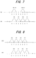
- the symbol-phase-rotation unit 15 performs phase rotation that increases in increments of ⁇ for each of the symbols D1
- the frequency spectrum becomes as shown in (B) of Fig. 7 . From (B) of Fig.
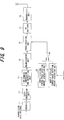
- Fig. 9 is a block diagram of a frequency-division multiplexing transmission apparatus of a second embodiment, and the same reference numbers are assigned to parts that are identical with those of the first embodiment shown in Fig. 1 .
- the difference between Fig. 1 and 9 is that the phase-rotation units 15 and 16 in Fig.1 are combined to be a single phase-rotation unit 25 in Fig.25.
- An encoder 11 performs channel encoding by applying error-correction encoding such as turbo encoding, or convolutional encoding to the input binary information sequence, and a data-modulation unit 12 converts the channel-encoded data sequence to I, Q complex componen ts (symbols) in QPSK, for example.
- Tc Tc x Q.
- a phase-rotation unit 25 performs phase rotation specific to the symbols D0, D1 and the mobile station for each respective symbol of the rearranged repetitive-symbol sequence, and as shown in (e) of Fig. 2 , a CP-attachment unit 17 attaches a CP (Cyclic Prefix) to the start of the repetitive-symbol sequence for each IFDMA symbol, and a transmission unit 18 performs up-conversion of the frequency of the symbol sequence to which a CP is attached from a baseband frequency to a radio frequency, then amplifies the signal and transmits it from an antenna.
- CP-attachment unit 17 attaches a CP (Cyclic Prefix) to the start of the repetitive-symbol sequence for each IFDMA symbol
- a transmission unit 18 performs up-conversion of the frequency of the symbol sequence to which a CP is attached from a baseband frequency to a radio frequency, then amplifies the signal and transmits it from an antenna.
- a mobile-station/symbol-phase rotation amount generation unit 26 generates the amount of phase rotation corresponding to the mobile station and symbols D0
- a mobile-station/symbol-phase rotation amount generation unit 27 generates the amount of phase rotation corresponding to the mobile station and symbols D1.
- the symbols D0, D1 are alternately input to the phase-rotation unit 15, and in synchronization with that, a switch 28 alternately inputs the amount of phase rotation generated by the mobile-station/symbol-phase rotation amount generation units 26, 27 to the phase-rotation unit 25.
- the mobile-station/symbol-phase rotation amount generation unit 26 generates the phase-rotation amount for the symbols D0 after each period Ts of symbol repetition as 0 ⁇ 0 + 2 x ⁇ ⁇ k / 4 ⁇ 0 + 4 x ⁇ ⁇ k / 4 ⁇ 0 + 6 x ⁇ ⁇ k / 4 ⁇ ... Also, the mobile-station/symbol-phase rotation amount generation unit 27 generates the phase-rotation amount for the symbols D1 after each period Ts of symbol repetition as 0 + ⁇ ⁇ k / 4 ⁇ ⁇ + 3 x ⁇ ⁇ k / 4 ⁇ 2 ⁇ ⁇ + 5 x ⁇ ⁇ k / 4 ⁇ 3 ⁇ ⁇ + 7 x ⁇ ⁇ k / 4 ⁇ ...
- the switch 28 alternately input
- the frequency-division multiplexing receiving apparatus has the same construction as the frequency-division multiplexing receiving apparatus of the first embodiment shown in Fig. 5 .
- Fig. 10 is a block diagram of a wave-number-division multiplexing transmission apparatus of a third embodiment of the invention that transmits data by a wave-number spectrum
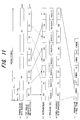
- Fig. 11 is a timing chart for explaining the operation of the wave-number-division multiplexing transmission apparatus shown in Fig. 10
- the wave-number-division multiplexing transmission apparatus of this third embodiment can be used as a mobile station.
- An encoder 51 performs channel encoding by applying error-correction encoding such as turbo encoding, or convolutional encoding to the input binary information sequence
- a data-modulation unit 52 converts the channel-encoded data sequence to I, Q complex components (symbols) in QPSK, for example.
- Tc Tc x Q.
- spreading-code-generation units 55, 56 use Walsh code to generate orthogonal spreading code specific to the symbols and the mobile station. For example, expressing the nth element of the nth wave-number code of the Walsh code as Wal(m,n), the spreading-code-generation unit 55 generates at each symbol period Tc a spreading-code sequence Wal(0,0), Wal(0,1), Wal(0,2), Wal(0,3), Wal(0,4), Wal(0,5), Wal(0,6), Wal(0,7) each of which is multiplied with the symbol D0.
- the spreading-code-generation unit 56 generates the spreading-code sequence Wal(2,0), Wal(2,1), Wal(2,2), Wal(2,3), Wal(2,4), Wal(2,5), Wal(2,6), Wal(2,7) each of which is multiplied with the symbol D1.
- a switch 60 alternately selects the generated code from the spreading-code-generation units 55, 56 at each symbol period Tc, and inputs the code to a spreading-code multiplier 57, and the spreading-code multiplier 57 multiplies the rearranged repetitive symbols D0, D1 by the spreading code and performs the spreading process.
- the spread symbol sequence becomes as shown in (e) of Fig. 11 .
- a CP-attachment unit 58 attaches a CP (Cyclic Prefix) to the start of the symbol sequence which is multiplied by spreading code, and a transmission unit 59 performs up-conversion of the frequency of the symbol sequence to which the CP has been attached from a baseband frequency to a radio frequency, and then amplifies the signal and transmits it from an antenna.
- CP Cyclic Prefix
- the spreading-code-generation units 55, 56 use Walsh code to generate orthogonal spreading code specific to the symbols and mobile station as shown below.
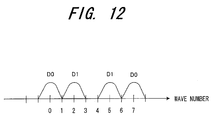
- the code for wave number w0 and wave number w7 is the same, so as shown in Fig. 12 , the symbols D0 are output in wave number w0 and w7.
- the symbols D1 are spread using the code for wave number w2
- the symbols D1 are multiplied every other one by the code for wave number w2.
- the code for wave number w2 and wave number -1 x w5 is the same, so as shown in Fig. 12 , the symbols D1 are output in wave numbers w2 and w5 (the phase is reverse).
- the wave spectrum shown in Fig. 12 can be obtained by performing Walsh conversion of the transmission signal.
- the Walsh conversion equation G(m) is defined as given below.
- g D ⁇ 0 D ⁇ 1 D ⁇ 0 - D ⁇ 1 D ⁇ 0 - D ⁇ 1 D ⁇ 0 D ⁇ 1 so the Walsh conversion equation is expressed by the following equations.
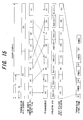
- Fig. 13 is a block diagram of a wave-number-division multiplexing receiving apparatus of this third embodiment of the invention.
- Awireless-receivingunit 71 receives a radio signal and performs down conversion of the frequency to a baseband signal
- the an orthogonal-demodulation unit 72 performs QPSK demodulation of the baseband signal
- an AD converter converts the demodulated result (received symbol sequence) to digital and inputs the result to a symbol-timing-detection unit 73 and serial/parallel converter 74.
- the symbol-timing-detection unit 73 detects the IWDMA symbol timing (frame symbol timing) from the received symbol sequence, and the serial/parallel converter 74 deletes the CP from the received symbol sequence based on the IWDMA symbol timing, and performs serial-to-parallel conversion of the received symbol sequence.
- a Walsh WFT unit 75 performs WFT conversion of the symbol data that has been converted to parallel data, and generates a plurality of wave- number components (wave- number spectrum). In the case of the example shown in Fig. 12 , symbol data D0, D1, D0, D1 are output in correspondence to the wave numbers w0, w2, w5, w7 as wave number components.
- a wave-number combiner 76 combines the components of wave numbers w0, w7 and outputs the result as symbol data D0, and combines the sub-carrier omponents of wave numbers w2, w5 and outputs the result as symbol data D1.
- a decoder 77 performs error-correction decoding of the symbols D0, D1 that are input, and inputs the result to a data processing unit (not shown in the figure).
- n the noise at each sampling point.
- R 0 D ⁇ 0 + n 0
- R 1 D ⁇ 1 + n 1
- R 2 D ⁇ 0 + n 2
- R 3 - D ⁇ 1 + n 3
- R 4 D ⁇ 0 + n 4
- R 5 - D ⁇ 1 + n 5
- R 6 D ⁇ 0 + n 6
- R 7 D ⁇ 1 + n 7
- the signal component for wave number w0 is given by the following equation.
- the signal component for wave number w7 is given by the following equation.
- S 0 + S 7 8 ⁇ D ⁇ 0 + 2 ⁇ n 0 + n 2 + n 4 + n 6 and SNR is given by the following equation.
- Fig. 14 shows an example in a case where there is multi-path interference in Fig.14, (a) is a direct wave, (b) is a delay wave, and (c) is a received sample sequence composed of a combination of the direct wave and delay wave.
- the figure shows an example in which the delay wave is delayed one sample from the direct wave.
- the received signals of a 2-path model are expressed by the following equations.
- Fig. 15 is a timing chart for explaining the operation of a second mobile station, and is an example of using w1, w6, w3, w4 as spreading code for the second mobile station.
- symbols D0 are mul tipl ied by the code of wave number w1 every other one.
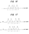
- wave number w1 and wave number w6 are the same code, so as shown in Fig. 16 , the symbols D0 are output at wave numbers w1 and w6.
- symbols D1 are multiplied by the code of wave number w3 every other one.
- wave number w3 and wave number -1 x w4 are the same code, so as shown in Fig. 16 , symbols D1 are output at wave numbers w2 and w4.
- the wave number spectrum shown in Fig. 16 can be obtained by performing Walsh conversion of the transmission signal. Similar to the case of the first mobile station, the signal of the second mobile station and result of Walsh conversion are given by the equations below.
- Fig. 17 shows the combined wave number spectrum for the first mobile station (UE0) and second mobile station (UE1). As shown in Fig. 17 , the first mobile station and second mobile station are multiplexed using orthogonal wave numbers. Therefore it is possible to reduce MAI. As can be seen from above explanation, with this third embodiment, it is possible to reduce multi-path interference without the need of a multi-path interference canceller.
- Fig. 18 is a block diagram of a frequency-division multiplexing transmission apparatus of a fourth embodiment of the invention
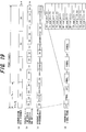
- Fig. 19 is a timing chart for explaining the operation of the frequency-division multiplexing transmission apparatus shown in Fig. 18
- the frequency-division multiplexing transmission apparatus of this fourth embodiment can be used as a base station.
- An encoder 81 performs channel encoding by applying error-correction encoding such as turbo encoding, or convolutional encoding to the input binary information sequence
- a data-modulation unit 82 converts the channel-encoded data sequence to I, Q complex components (symbols) in QPSK, for example.
- error-correction encoding such as turbo encoding, or convolutional encoding
- Symbol-phase-rotation-amount-generation units 85 0 , 85 1 , 85 2 , 85 3 of a phase-rotation-amount-generation unit 85 generate phase-rotation amounts specific to the symbols for each of the symbols D0, D1, D2, 03, and at the timingof the symbols D0, D1, D2, D3, a selector 86 inputs the phase-rotation amounts that are output from the corresponding symbol-phase-rotation-amount-generation units 85 0 , 85 1 , 85 2 , 85 3 to a data-phase-rotation unit 87.
- the symbol-phase-rotation-amount-generation unit 85 0 generates 0 as the phase-rotation amount for symbols D0
- the data-phase-rotation unit 87 multiplies the rearranged repeated symbols D0, D1, D2, D3 by the phase-rotation amounts specific for each symbol that is output from the selector 86.
- the symbol sequence after phase rotation becomes as shown in (c) of Fig. 19 .
- a CP-attachment unit 88 attaches a CP (Cyclic Prefix) to the start of the symbol sequence for which phase rotation was performed for each IFDMA symbol, and a transmission unit 89 performs up-conversion of the frequency of the symbol sequence to which a CP is attached from a baseband frequency to a radio frequency, then amplifies the signal and transmits it from an antenna.
- Fig. 20 shows the frequency spectrum of this fourth embodiment.
- the frequency-division multiplexing receiving apparatus of the fourth embodiment of the invention comprises: a wireless-receiving unit; an orthogonal-demodulation unit; a CP-removal unit; a phase-rotation unit that performs phase rotation that is reverse that of the transmission apparatus; a sub-carrier-combiner that combines the components of frequencies f0, f4 and outputs the result as symbol data D0, combines the components of frequencies f1, f5 and outputs the result as symbol data D1, combines the components of frequencies f2, f6 and outputs the result as symbol data D2, and combines the components of frequencies f3, f7 and outputs the result as symbol data D3; and a decoder to which the symbols D0, D1, D2, D3 are input, and that performs error-correction decoding and inputs the result to a data-processing unit.
- symbols D0 are output in frequencies f0, f4, symbols D1 are output in frequencies f1, f5, symbols D2 are output in frequencies f2, f6, and symbols D3 are output in frequencies f3, f7.
- the signal becomes a pseudo-like OFDM signal, and together with improving resistance to multi-path interference, a frequency-diversity effect occurs.
- the signal is created by time-division multiplexing, so PAPR does not become large.
- a frequency-division multiplexing transmission apparatus that transmits data in a frequency spectrum specific to both symbol and mobile station, and comprising:
- a frequency-division multiplexing transmission apparatus that transmits data in a frequency spectrum specific to both symbol and mobile station, and comprising:
- a wave-number-division multiplexing transmission apparatus that transmits data in a wave-number spectrum specific to both symbol and mobile station, and comprising:
- a wave-number-division multiplexing receiving apparatus of statement 4 or statement 5, comprising:
- a frequency-division multiplexing transmission apparatus that transmits data in a frequency spectrum specific to both symbol and mobile station, and comprising:
- a frequency-division multiplexing transmission method for transmitting data in a frequency spectrum specific to both symbol and mobile station comprising:
- a frequency-division multiplexing transmission method for transmitting data in a frequency spectrum specific to both symbol and mobile station comprising:
- a frequency-division-multiplexing-receiving method of statement 8 or statement 9, comprising:
- a wave-number-division multiplexing transmission method for transmitting data in a wave-number spectrum specific to both symbol and mobile station comprising:
- a wave-number-division multiplexing receiving method of statement 11 or statement 12, comprising:
- a frequency-division multiplexing transmission method for transmitting data in a frequency spectrum specific to both symbol and mobile station comprising:
Landscapes
- Engineering & Computer Science (AREA)
- Signal Processing (AREA)
- Computer Networks & Wireless Communication (AREA)
- Mobile Radio Communication Systems (AREA)
- Digital Transmission Methods That Use Modulated Carrier Waves (AREA)
Applications Claiming Priority (2)
| Application Number | Priority Date | Filing Date | Title |
|---|---|---|---|
| JP2006070152A JP5041715B2 (ja) | 2006-03-15 | 2006-03-15 | 周波数分割多重送受信装置及びその方法 |
| EP20060253728 EP1835679A3 (fr) | 2006-03-15 | 2006-07-17 | Réduction de l'interférence multi-voies. |
Related Parent Applications (1)
| Application Number | Title | Priority Date | Filing Date |
|---|---|---|---|
| EP06253728.7 Division | 2006-07-17 |
Publications (2)
| Publication Number | Publication Date |
|---|---|
| EP2282408A2 true EP2282408A2 (fr) | 2011-02-09 |
| EP2282408A3 EP2282408A3 (fr) | 2011-02-23 |
Family
ID=38198200
Family Applications (2)
| Application Number | Title | Priority Date | Filing Date |
|---|---|---|---|
| EP20060253728 Withdrawn EP1835679A3 (fr) | 2006-03-15 | 2006-07-17 | Réduction de l'interférence multi-voies. |
| EP20100189317 Withdrawn EP2282408A3 (fr) | 2006-03-15 | 2006-07-17 | Appareil d'émetteur-récepteur à multiplexage par répartition en fréquences, appareil d'émetteur-récepteur à multiplexage par réparation du nombre d'ondes et son procédé |
Family Applications Before (1)
| Application Number | Title | Priority Date | Filing Date |
|---|---|---|---|
| EP20060253728 Withdrawn EP1835679A3 (fr) | 2006-03-15 | 2006-07-17 | Réduction de l'interférence multi-voies. |
Country Status (4)
| Country | Link |
|---|---|
| US (2) | US7684463B2 (fr) |
| EP (2) | EP1835679A3 (fr) |
| JP (1) | JP5041715B2 (fr) |
| CN (2) | CN101039298B (fr) |
Families Citing this family (18)
| Publication number | Priority date | Publication date | Assignee | Title |
|---|---|---|---|---|
| US8483240B2 (en) * | 2006-12-19 | 2013-07-09 | Lockheed Martin Corporation | Piggyback networks |
| US7885289B2 (en) * | 2006-12-19 | 2011-02-08 | Lockheed Martin Corporation | System and method for relaying turbo-coded piggyback messages |
| US20080159356A1 (en) * | 2006-12-28 | 2008-07-03 | Samsung Electronics Co., Ltd. | Method and a system for low-rate channel communication in wireless communication systems |
| JP5355936B2 (ja) * | 2007-06-28 | 2013-11-27 | 日本信号株式会社 | リーダライタ、及び物品仕分システム |
| US8130851B2 (en) * | 2007-09-26 | 2012-03-06 | Nec Laboratories America, Inc. | Bandwidth efficient coding for an orthogonal frequency multiplexing OFDM system |
| US8483134B2 (en) * | 2008-06-17 | 2013-07-09 | Panasonic Corporation | Radio transmission appratus and radio transmission method that switch between communication methods |
| WO2010052800A1 (fr) * | 2008-11-05 | 2010-05-14 | Ntt Docomo, Inc. | Etalement de code bidimensionnel pour système fdma entrelacé |
| JP5420275B2 (ja) * | 2009-03-03 | 2014-02-19 | 株式会社Nttドコモ | 符号多重伝送方法、送信装置及び受信装置 |
| JP5678420B2 (ja) * | 2009-09-01 | 2015-03-04 | 富士通株式会社 | 中継方法及び中継装置 |
| JP5218522B2 (ja) * | 2010-10-25 | 2013-06-26 | 富士通株式会社 | 波数分割多重送受信装置及びその送信方法 |
| JP5540146B2 (ja) | 2011-02-21 | 2014-07-02 | パナソニック株式会社 | プリコーディング方法、プリコーディング装置 |
| JP5737999B2 (ja) * | 2011-02-25 | 2015-06-17 | 三菱電機株式会社 | 通信システム、送信機および受信機 |
| CN102412867B (zh) * | 2011-12-07 | 2014-04-16 | 清华大学 | 基于时频交织单载波频域均衡的直流分量克服方法和系统 |
| JP7002185B2 (ja) * | 2015-07-30 | 2022-01-20 | パナソニック インテレクチュアル プロパティ コーポレーション オブ アメリカ | 送信方法、送信装置、受信方法、受信装置 |
| MY185466A (en) * | 2018-02-27 | 2021-05-19 | Mitsubishi Electric Corp | Wireless transmitter, wireless receiver, wireless communication system, control circuit, and storage medium |
| CN115968537B (zh) * | 2020-09-02 | 2024-06-28 | 三菱电机株式会社 | 发送装置、接收装置以及基站 |
| JP7237259B2 (ja) * | 2021-03-03 | 2023-03-10 | 三菱電機株式会社 | 送信装置 |
| JP7848522B2 (ja) * | 2022-03-10 | 2026-04-21 | 日本電気株式会社 | 高速フーリエ変換装置、デジタルフィルタ装置、高速フーリエ変換方法、及びプログラム |
Citations (1)
| Publication number | Priority date | Publication date | Assignee | Title |
|---|---|---|---|---|
| JP2004297756A (ja) | 2003-02-06 | 2004-10-21 | Ntt Docomo Inc | 移動局、基地局、無線伝送プログラム、及び無線伝送方法 |
Family Cites Families (8)
| Publication number | Priority date | Publication date | Assignee | Title |
|---|---|---|---|---|
| JP2778498B2 (ja) * | 1995-01-11 | 1998-07-23 | 日本電気株式会社 | スペクトラム拡散ダイバーシチ送受信機 |
| JP3558811B2 (ja) * | 1997-01-31 | 2004-08-25 | ティーオーエー株式会社 | 変調器及び変調方法、復調器及び復調方法 |
| JPH11266224A (ja) * | 1998-03-18 | 1999-09-28 | Nippon Telegr & Teleph Corp <Ntt> | 直交周波数多重通信装置 |
| US7103026B2 (en) * | 2000-10-27 | 2006-09-05 | L-3 Communications Corporation | Use of chip repetition to produce a flexible bandwidth DS-CDMA system |
| US7003045B2 (en) * | 2001-01-31 | 2006-02-21 | Motorola, Inc. | Method and apparatus for error correction |
| KR100754721B1 (ko) * | 2002-04-26 | 2007-09-03 | 삼성전자주식회사 | 직교주파수분할다중화 통신시스템에서 다중화 데이터 송수신 장치 및 방법 |
| JP4583054B2 (ja) * | 2004-03-05 | 2010-11-17 | 株式会社エヌ・ティ・ティ・ドコモ | 移動局および基地局 |
| US8000268B2 (en) * | 2004-06-30 | 2011-08-16 | Motorola Mobility, Inc. | Frequency-hopped IFDMA communication system |
-
2006
- 2006-03-15 JP JP2006070152A patent/JP5041715B2/ja not_active Expired - Fee Related
- 2006-07-13 US US11/486,262 patent/US7684463B2/en not_active Expired - Fee Related
- 2006-07-17 EP EP20060253728 patent/EP1835679A3/fr not_active Withdrawn
- 2006-07-17 EP EP20100189317 patent/EP2282408A3/fr not_active Withdrawn
- 2006-08-25 CN CN2006101261536A patent/CN101039298B/zh not_active Expired - Fee Related
- 2006-08-25 CN CN2010101674728A patent/CN101860511B/zh not_active Expired - Fee Related
-
2009
- 2009-11-11 US US12/616,238 patent/US7873096B2/en not_active Expired - Fee Related
Patent Citations (1)
| Publication number | Priority date | Publication date | Assignee | Title |
|---|---|---|---|---|
| JP2004297756A (ja) | 2003-02-06 | 2004-10-21 | Ntt Docomo Inc | 移動局、基地局、無線伝送プログラム、及び無線伝送方法 |
Non-Patent Citations (1)
| Title |
|---|
| GOTO ET AL.: "Investigations on Packet Error Rate of Variable Spreading and Chip Repetition Factors (VSCRF)-CDMA Wireless Access in Reverse Link Multi-cell Environment", THE INSTITUTE OF ELECTRONICS, INFORMATION AND COMMUNICATION ENGINEERS, TECHNICAL REPORT OF IEICE, pages 204 - 206 |
Also Published As
| Publication number | Publication date |
|---|---|
| JP5041715B2 (ja) | 2012-10-03 |
| CN101039298B (zh) | 2012-05-30 |
| US7684463B2 (en) | 2010-03-23 |
| EP2282408A3 (fr) | 2011-02-23 |
| CN101039298A (zh) | 2007-09-19 |
| CN101860511A (zh) | 2010-10-13 |
| US7873096B2 (en) | 2011-01-18 |
| EP1835679A3 (fr) | 2010-05-05 |
| EP1835679A2 (fr) | 2007-09-19 |
| CN101860511B (zh) | 2012-01-04 |
| JP2007251451A (ja) | 2007-09-27 |
| US20100103984A1 (en) | 2010-04-29 |
| US20070217485A1 (en) | 2007-09-20 |
Similar Documents
| Publication | Publication Date | Title |
|---|---|---|
| US7873096B2 (en) | Frequency-division multiplexing transceiver apparatus, wave-number-division multiplexing transceiver apparatus and method thereof | |
| US7952991B2 (en) | Method and apparatus for transmitting and receiving control information in a single carrier FDMA system | |
| US8000268B2 (en) | Frequency-hopped IFDMA communication system | |
| US8005063B2 (en) | Uplink channel receiving and transmitting apparatuses and methods | |
| US8305989B2 (en) | Method for allocating pilots | |
| EP1770894B1 (fr) | Dispositif et méthode de multiplexage par répartition en fréquences | |
| US7630454B2 (en) | Frequency-division multiplexing transceiver apparatus and method | |
| US6996080B1 (en) | Chip-synchronous CDMA multiplexer and method resulting in constant envelope signals | |
| EP1821475B1 (fr) | Appareil émetteur récepteur à multiplexage par division de fréquences et méthode associée | |
| JP5218522B2 (ja) | 波数分割多重送受信装置及びその送信方法 | |
| EP1989786B1 (fr) | Étalement parallèle générique | |
| JP2009273169A (ja) | 上りリンクにおける物理チャネルの無線リソース割り当て方法および移動機用送信機 | |
| MXPA00002633A (en) | A method of and apparatus for transmitting data in a multiple carrier system |
Legal Events
| Date | Code | Title | Description |
|---|---|---|---|
| PUAI | Public reference made under article 153(3) epc to a published international application that has entered the european phase |
Free format text: ORIGINAL CODE: 0009012 |
|
| PUAL | Search report despatched |
Free format text: ORIGINAL CODE: 0009013 |
|
| AC | Divisional application: reference to earlier application |
Ref document number: 1835679 Country of ref document: EP Kind code of ref document: P |
|
| AK | Designated contracting states |
Kind code of ref document: A2 Designated state(s): DE FR GB IT |
|
| AK | Designated contracting states |
Kind code of ref document: A3 Designated state(s): DE FR GB IT |
|
| RIC1 | Information provided on ipc code assigned before grant |
Ipc: H04L 5/00 20060101ALI20110114BHEP Ipc: H04L 27/26 20060101AFI20110114BHEP |
|
| 17P | Request for examination filed |
Effective date: 20110818 |
|
| 17Q | First examination report despatched |
Effective date: 20111222 |
|
| STAA | Information on the status of an ep patent application or granted ep patent |
Free format text: STATUS: THE APPLICATION IS DEEMED TO BE WITHDRAWN |
|
| 18D | Application deemed to be withdrawn |
Effective date: 20160426 |