EP2282553A2 - Basstonverstärkungshülle, Woofer damit und elektronische Vorrichtung mit dem Woofer - Google Patents
Basstonverstärkungshülle, Woofer damit und elektronische Vorrichtung mit dem Woofer Download PDFInfo
- Publication number
- EP2282553A2 EP2282553A2 EP10157372A EP10157372A EP2282553A2 EP 2282553 A2 EP2282553 A2 EP 2282553A2 EP 10157372 A EP10157372 A EP 10157372A EP 10157372 A EP10157372 A EP 10157372A EP 2282553 A2 EP2282553 A2 EP 2282553A2
- Authority
- EP
- European Patent Office
- Prior art keywords
- chamber
- speaker unit
- plate
- woofer
- enclosure
- Prior art date
- Legal status (The legal status is an assumption and is not a legal conclusion. Google has not performed a legal analysis and makes no representation as to the accuracy of the status listed.)
- Granted
Links
Images


Classifications
-
- H—ELECTRICITY
- H04—ELECTRIC COMMUNICATION TECHNIQUE
- H04R—LOUDSPEAKERS, MICROPHONES, GRAMOPHONE PICK-UPS OR LIKE ACOUSTIC ELECTROMECHANICAL TRANSDUCERS; ELECTRIC HEARING AIDS; PUBLIC ADDRESS SYSTEMS
- H04R1/00—Details of transducers, loudspeakers or microphones
- H04R1/20—Arrangements for obtaining desired frequency or directional characteristics
- H04R1/22—Arrangements for obtaining desired frequency or directional characteristics for obtaining desired frequency characteristic only
- H04R1/28—Transducer mountings or enclosures modified by provision of mechanical or acoustic impedances, e.g. resonator, damping means
- H04R1/2807—Enclosures comprising vibrating or resonating arrangements
- H04R1/2815—Enclosures comprising vibrating or resonating arrangements of the bass reflex type
- H04R1/2819—Enclosures comprising vibrating or resonating arrangements of the bass reflex type for loudspeaker transducers
-
- H—ELECTRICITY
- H04—ELECTRIC COMMUNICATION TECHNIQUE
- H04N—PICTORIAL COMMUNICATION, e.g. TELEVISION
- H04N5/00—Details of television systems
- H04N5/64—Constructional details of receivers, e.g. cabinets or dust covers
-
- H—ELECTRICITY
- H04—ELECTRIC COMMUNICATION TECHNIQUE
- H04R—LOUDSPEAKERS, MICROPHONES, GRAMOPHONE PICK-UPS OR LIKE ACOUSTIC ELECTROMECHANICAL TRANSDUCERS; ELECTRIC HEARING AIDS; PUBLIC ADDRESS SYSTEMS
- H04R1/00—Details of transducers, loudspeakers or microphones
- H04R1/02—Casings; Cabinets ; Supports therefor; Mountings therein
-
- H—ELECTRICITY
- H04—ELECTRIC COMMUNICATION TECHNIQUE
- H04R—LOUDSPEAKERS, MICROPHONES, GRAMOPHONE PICK-UPS OR LIKE ACOUSTIC ELECTROMECHANICAL TRANSDUCERS; ELECTRIC HEARING AIDS; PUBLIC ADDRESS SYSTEMS
- H04R1/00—Details of transducers, loudspeakers or microphones
- H04R1/20—Arrangements for obtaining desired frequency or directional characteristics
- H04R1/22—Arrangements for obtaining desired frequency or directional characteristics for obtaining desired frequency characteristic only
- H04R1/26—Spatial arrangements of separate transducers responsive to two or more frequency ranges
-
- H—ELECTRICITY
- H04—ELECTRIC COMMUNICATION TECHNIQUE
- H04R—LOUDSPEAKERS, MICROPHONES, GRAMOPHONE PICK-UPS OR LIKE ACOUSTIC ELECTROMECHANICAL TRANSDUCERS; ELECTRIC HEARING AIDS; PUBLIC ADDRESS SYSTEMS
- H04R1/00—Details of transducers, loudspeakers or microphones
- H04R1/20—Arrangements for obtaining desired frequency or directional characteristics
- H04R1/22—Arrangements for obtaining desired frequency or directional characteristics for obtaining desired frequency characteristic only
- H04R1/28—Transducer mountings or enclosures modified by provision of mechanical or acoustic impedances, e.g. resonator, damping means
- H04R1/2807—Enclosures comprising vibrating or resonating arrangements
- H04R1/2853—Enclosures comprising vibrating or resonating arrangements using an acoustic labyrinth or a transmission line
- H04R1/2857—Enclosures comprising vibrating or resonating arrangements using an acoustic labyrinth or a transmission line for loudspeaker transducers
-
- H—ELECTRICITY
- H04—ELECTRIC COMMUNICATION TECHNIQUE
- H04R—LOUDSPEAKERS, MICROPHONES, GRAMOPHONE PICK-UPS OR LIKE ACOUSTIC ELECTROMECHANICAL TRANSDUCERS; ELECTRIC HEARING AIDS; PUBLIC ADDRESS SYSTEMS
- H04R2499/00—Aspects covered by H04R or H04S not otherwise provided for in their subgroups
- H04R2499/10—General applications
- H04R2499/15—Transducers incorporated in visual displaying devices, e.g. televisions, computer displays, laptops
Definitions
- Apparatuses consistent with the present invention relate to a bass sound amplifying enclosure, a woofer including the bass sound amplifying enclosure, and an electronic device including the woofer.
- a bar type speaker installed in a lower bezel below a flat display panel prevents digital TVs from becoming thicker.
- the bar type speaker has a low sound pressure level in a bass sound bandwidth of 100 ⁇ 300 Hz and thus the sound quality thereof is unsatisfactory.
- Exemplary embodiments of the present invention aim to address at least the above problems and/or disadvantages and other disadvantages not described above. Also, the present invention is not required to overcome the disadvantages described above, and an exemplary embodiment of the present invention may not overcome any of the problems described above.
- the present invention provides a thin bass sound amplifying enclosure suitable for a slim type electronic device, a woofer including the thin bass sound amplifying enclosure, and an electronic device including the woofer.
- an enclosure including a rear chamber; a speaker unit chamber disposed adjacent to the rear chamber and including a speaker unit which generates a sound vibration; a front chamber disposed adjacent to the speaker unit chamber; and a duct having a first side which is connected to the front chamber such that air flows between the front chamber and the duct and a second side opened to the outside, wherein the rear chamber, the speaker unit chamber, the front chamber, and the duct are disposed between a first plate and a second plate that are spaced apart from each other, wherein the rear chamber and the speaker unit chamber are connected to each other through an aperture formed closer to the first plate than the second plate in a first barrier rib that partitions the rear chamber and the speaker unit chamber, and wherein the front chamber and the speaker unit chamber are connected to each through an aperture formed closer to the second plate than the first plate in a second barrier rib that partitions the front chamber and the speaker unit chamber.
- an electronic device include: a main body which performs a previously established function; and a woofer, attached to the main body, and which amplifies a bass sound
- the woofer comprises an enclosure comprising a rear chamber, a speaker unit chamber disposed adjacent to the rear chamber and connected to the rear chamber such that air flows between the rear chamber and the speaker unit chamber, a front chamber disposed adjacent to the speaker unit chamber and connected to the speaker unit chamber such that air flows between the front chamber and the speaker unit chamber, and a duct having a first side connected to the front chamber such that air flows between the duct and the front chamber and a second side opened to the outside, wherein the rear chamber, the speaker unit chamber, the front chamber, and the duct are disposed between a first plate and a second plate that are spaced apart from each other; and a speaker unit which generates a sound vibration disposed in the speaker unit chamber such that a front surface faces the second plate.
- a gap between the front surface of the speaker unit and the inner side surface of the second plate may be greater than a maximum vibration amplitude of the speaker unit.
- An aperture which disperses the sound vibration generated by the speaker unit may be formed in a portion of the second plate that overlaps the speaker unit chamber and the front chamber.
- the aperture formed in the second plate may be closed by a portion of the main body.
- a gap between the front surface of the speaker unit and the portion of the main body may be greater than a maximum vibration amplitude of the speaker unit.
- An aperture may be formed in a portion of the first plate that overlaps the speaker unit chamber, and the speaker unit may be partially inserted into the aperture formed in the first plate.
- the first plate or the second plate may include a reinforcement unit that inhibits vibration and reinforces rigidity.
- the rear chamber and the speaker unit chamber may be spaced apart from the duct by the front chamber.
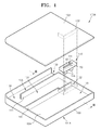
- FIG. 1 is an exploded perspective view of a woofer according to an exemplary embodiment of the present invention
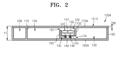
- FIG. 2 is a cross-sectional view of the woofer of FIG. 1 taken along a line II-II according to an exemplary embodiment of the present invention
- FIG. 3 is an exploded perspective view of a woofer according to another exemplary embodiment of the present invention.
- FIG. 4 is a cross-sectional view of the woofer of FIG. 3 taken along a line IV-IV according to another exemplary embodiment of the present invention
- FIG. 5A is a plan view of an inner side surface of a first plate included in an enclosure according to an exemplary embodiment of the present invention.
- FIG. 5B is a plan view of an inner side surface of a second plate included in an enclosure according to an exemplary embodiment of the present invention.
- FIG. 6 is a perspective view of an electronic device according to an exemplary embodiment of the present invention.
- FIG. 7 is a graph of a sound pressure level of the electronic device of FIG. 6 according to an exemplary embodiment of the present invention.
- FIG. 1 is an exploded perspective view of a woofer 100A according to an exemplary embodiment of the present invention.
- FIG. 2 is a cross-sectional view of the woofer 100A of FIG. 1 taken along a line II-II according to an exemplary embodiment of the present invention.
- the woofer 100A of the exemplary embodiment includes first and second plates 102A and 120A that are in parallel spaced apart from each other, an enclosure 101A including an external wall 103 that is an external boundary, and a speaker unit 140 that is mounted in the enclosure 101A and generates sound vibrations.
- the first plate 102A and the external wall 103 are integrally formed so that a base is formed.
- the second plate 120A is coupled to the base so that the enclosure 101A is formed.
- the inner space of the enclosure 101A is divided into a rear chamber 130, a speaker unit chamber 132, a front chamber 134, and a duct 136 according to first through third barrier ribs 105, 122, and 110.
- the first barrier rib 105 partitions the rear chamber 130, the speaker unit chamber 132, and the front chamber 134.
- the second barrier rib 122 partitions the speaker unit chamber 132 and the rear chamber 130.
- the third barrier rib 110 partitions the front chamber 134 and the duct 136.
- the first barrier rib 105 and the third barrier rib 110 are integrally formed with the first plate 102A
- the second barrier rib 122 is integrally formed with the second plate 120A.
- the rear chamber 130 is not directly connected to the outside of the enclosure 101A, in order to facilitate air flow, the rear chamber 130 is adjacent to the speaker unit chamber 132 with the second barrier rib 122 disposed therebetween, with a first connection aperture 124 formed in the second barrier rib 122.
- the speaker unit chamber 132 is adjacent to the front chamber 134 with the first barrier rib 105 disposed therebetween, and air flow is facilitated through a second connection aperture 107 formed in the first barrier rib 105.
- the front chamber 134 is connected to one side of the duct 136 through a third connection aperture 138 formed in one side of the third barrier rib 110 in order to facilitate air flow, and the other side of the duct 136 is opened to the outside through a duct aperture 139.
- the rear chamber 130 and the speaker unit chamber 132 are spaced apart from the duct 139 by the front chamber 134.
- the first connection aperture 124 and the second connection aperture 107 are not disposed in the same level between the first plate 102A and the second plate 120A.
- the first connection aperture 124 is formed closer to the first plate 102A and the second connection aperture 107 is formed closer to the second plate 120A.
- the speaker unit 140 is mounted in the speaker unit chamber 132 in such a manner that a front surface 141 in which sound vibration radiates faces the second plate 120A.
- the speaker unit 140 may be a bar type speaker.
- the speaker unit 140 includes a frame 143, a vibration plate 150 disposed in the frame 143 and generating sound vibration, a driving body 145 driving the vibration plate 150, and a magnet 148. If current corresponding a sound signal flows in a coil 146 winding around the driving body 145, the driving body 145 and the vibration plate 150 supported by the driving body 145 vibrate in a direction of thickness T1 of the enclosure 101A according to correlations between the driving body 145 and the vibration plate 150 and a magnet 148 and thus sound vibration radiates toward the second plate 120A.
- the sound vibration radiated toward the second plate 120A is reflected by the second plate 120A, passes through the second connection aperture 107, undergoes the front chamber 134 and the duct 136, and radiates to the outside of the enclosure 101A through the duct aperture 139.
- the sound radiates to the outside of the enclosure 101A by amplifying a bass sound bandwidth corresponding to a resonance frequency of the duct 136 according to a Helmholtz resonance effect.
- a gap G1 between the front surface 141 of the speaker unit 140 and an inner side surface of the second plate 120A is set to be greater than the maximum amplitude of the speaker unit 140 when the sound vibration radiates so that the speaker unit 140 does not prevent the sound vibration from radiating. Further, the gap G1 is set to be smaller than a wavelength (approximately, 1-3 m) of bass sound bandwidth sound that is to be amplified so that a bass sound amplification performance can not be deteriorated.
- the maximum amplitude of the speaker unit 140 and the vibrating plate 150 may be about 0.6 mm.
- the gap G1 may be about 2 mm.
- the thickness TP of the first plate 102A and the second plate 120A may be about 1 mm.
- the thickness T1 of the woofer 101A may be about 13 mm.
- FIG. 3 is an exploded perspective view of a woofer 100B according to another exemplary embodiment of the present invention.
- FIG. 4 is a cross-sectional view of the woofer 100B of FIG. 3 taken along a line IV-IV according to another exemplary embodiment of the present invention.
- the woofer 100B of the present exemplary embodiment is quite similar to the woofer 100A of the previous embodiment and is partially different from the woofer 100A.
- Like reference numerals denote like elements between the woofers 100A and 100B and thus the same descriptions thereof will not be repeated.
- the woofer 100B of the present exemplary embodiment includes first and second plates 102 B and 120 B that are in parallel spaced apart from each other, an enclosure 101B including the external wall 103 that is an external boundary, and the speaker unit 140 that is mounted in the enclosure 101B.
- the inner space of the enclosure 101B is divided into the rear chamber 130, the speaker unit chamber 132, the front chamber 134, and the duct 136 according to the first through the third barrier ribs 105, 122, and 110.
- a magnet aperture 114 is formed in a portion of the first plate 102B that overlaps the speaker unit chamber 132.
- the magnet 148 of the speaker unit chamber 132 is inserted into the magnet aperture 114.
- a sound dispersion aperture 125 that disperses sound vibration generated in the speaker unit 140 is formed in a portion of the second plate 120B that overlaps the speaker unit chamber 132 and the front chamber 134.
- the sound dispersion aperture 125 may be closed by an element of a main body 12 of an electronic device 10 when the woofer 100B is attached to the electronic device 10 as shown in FIG. 6 .
- the element of the main body 12 may be a flat display panel 15 that is wider and flatter than the second plate 120B, and the sound dispersion aperture 125 may be closed by a rear surface of the flat display panel 15.
- the sound vibration radiated in the speaker unit 140 travels forward the sound dispersion aperture 125 of the second plate 120B, is reflected by the rear surface of the flat display panel 15, undergoes the front chamber 134 and the duct 136 through the second connection aperture 107, and radiates to the outside of the enclosure 101B by amplifying a bass sound bandwidth through the duct aperture 139.
- a gap G2 between the front surface 141 of the speaker unit 140 and the rear surface of the flat display panel 15, i.e. an inner side surface of the flat display panel 15 facing the enclosure 101B, is set to be greater than the maximum amplitude of the speaker unit 140 when the sound vibration radiates so that the speaker unit 140 does not prevent the sound vibration from radiating. Further, the gap G2 is set to be smaller than a wavelength (approximately, 1-3 m) of bass sound bandwidth sound that is to be amplified so that a bass sound amplification performance can not be deteriorated.
- the maximum amplitude of the speaker unit 140 and the vibrating plate 150 may be about 0.6 mm.
- the gap G2 may be about 2 mm.
- the woofer 100B of the present exemplary embodiment further includes the magnet aperture 114 and the sound dispersion aperture 125 compared to the woofer 100A of the previous exemplary embodiment, a gap of the first plate 102B and the second plate 120B may be reduced to the thickness 2TP of the thickness of the first plate 102B and the second plate 120B.
- the thickness T2 of the woofer 100B may be smaller than the thickness T1 of the woofer 100A.
- FIG. 5A is a plan view of an inner side surface of a first plate 102C included in an enclosure according to an exemplary embodiment of the present invention.
- FIG. 5B is a plan view of an inner side surface of a second plate 120C included in an enclosure according to an exemplary embodiment of the present invention.
- the first plate 102C and first plate 120C of the present exemplary embodiment are quite similar to the first plate 102B and first plate 120B of the previous exemplary embodiment and are partially different from the first plate 102B and first plate 120B.
- Like reference numerals denote like elements between the first plate 102C and first plate 120C and the woofer 100B and thus the same descriptions thereof will not be repeated.
- the first plate 102C and first plate 120C include a reinforcement unit that inhibits vibration thereof caused by sound vibration and reinforces rigidity.
- two ribs 116 and 127 that protrude in the form of a check are formed in the inner side surfaces of the first plate 102C and first plate 120C.
- two screw holes 119 and 129 used for screw locking are formed at an anti-node point in which a great vibration is detected, which prevents a reduction in a sound pressure level caused by vibration of the anti-node point.
- the anti-node point can be experimentally found.
- FIG. 6 is a perspective view of an electronic device 10 according to an exemplary embodiment of the present invention.
- the electronic device 10 of the present exemplary embodiment is a digital TV but the present invention is not limited thereto.
- the electronic device 10 includes the main body 12 that performs a previously established function and a pair of woofers 100B attached to the main body 12. If the electronic device 10 is the digital TV, the main body 12 performs a function of visually displaying a recognizable scene and audibly radiating recognizable sound.
- the main body 12 includes the flat display panel 15 that displays a scene, a bar type speaker 18 disposed in the lower portion of the flat display panel 15, and a support 20 that supports the flat display panel 15.
- the woofer 100B is attached to the main body 12 so that the sound dispersion aperture 125 faces the main body 12, and the sound dispersion aperture 125 may be closed by the flat display panel 15.
- the speaker unit 140 radiates the sound vibration through the duct aperture 139 opened upward (see FIGS. 3 and 4 ).
- FIG. 7 is a graph of a sound pressure level of the electronic device 10 of FIG. 6 according to an exemplary embodiment of the present invention.
- the sound pressure level is measured 1.5 m in front of the electronic device 10 and is parametrically equalized (PEQ).
- a broken line indicates a sound pressure level of the electronic device 10 having a woofer.
- a solid line indicates a sound pressure level of the electronic device 10 excluding the woofer 100B.
- the electronic device 10 excluding the woofer 100B has a 6dB roll-off frequency of 290 Hz in which the sound pressure level rapidly falls by 6 dB in a low frequency band, whereas the electronic device 10 having the woofer has a 6dB roll-off frequency of 83 Hz and thus a frequency of about 200 Hz is reduced. Therefore, sound is amplified by the frequency of about 200 Hz in the bass sound bandwidth.
Landscapes
- Engineering & Computer Science (AREA)
- Signal Processing (AREA)
- Physics & Mathematics (AREA)
- Acoustics & Sound (AREA)
- Health & Medical Sciences (AREA)
- Otolaryngology (AREA)
- Multimedia (AREA)
- Details Of Audible-Bandwidth Transducers (AREA)
- Obtaining Desirable Characteristics In Audible-Bandwidth Transducers (AREA)
- Studio Devices (AREA)
Applications Claiming Priority (1)
| Application Number | Priority Date | Filing Date | Title |
|---|---|---|---|
| KR1020090068411A KR101629822B1 (ko) | 2009-07-27 | 2009-07-27 | 저음 증폭용 엔클로저, 상기 엔클로저를 구비한 우퍼, 및 상기 우퍼를 구비한 전자기기 |
Publications (3)
| Publication Number | Publication Date |
|---|---|
| EP2282553A2 true EP2282553A2 (de) | 2011-02-09 |
| EP2282553A3 EP2282553A3 (de) | 2013-03-13 |
| EP2282553B1 EP2282553B1 (de) | 2020-07-01 |
Family
ID=43033051
Family Applications (1)
| Application Number | Title | Priority Date | Filing Date |
|---|---|---|---|
| EP10157372.3A Not-in-force EP2282553B1 (de) | 2009-07-27 | 2010-03-23 | Basstonverstärkungshülle, Woofer damit und elektronische Vorrichtung mit dem Woofer |
Country Status (4)
| Country | Link |
|---|---|
| US (1) | US8351631B2 (de) |
| EP (1) | EP2282553B1 (de) |
| KR (1) | KR101629822B1 (de) |
| MX (1) | MX2010003957A (de) |
Cited By (4)
| Publication number | Priority date | Publication date | Assignee | Title |
|---|---|---|---|---|
| EP2905973A1 (de) * | 2014-02-07 | 2015-08-12 | LG Electronics Inc. | Lautsprecheranordnung, die in einer elektronischen Vorrichtung angeordnet ist |
| EP2999238A4 (de) * | 2013-05-15 | 2017-03-29 | Sony Corporation | Audioausgangsvorrichtung, audioausgabeverfahren, und videoanzeigevorrichtung |
| CN109104666A (zh) * | 2018-08-01 | 2018-12-28 | 美特科技(苏州)有限公司 | 扬声器及其音频设备、频响调节方法 |
| EP3525480A1 (de) * | 2018-02-07 | 2019-08-14 | Acer Incorporated | Erweiterungssystem von einem woofer und verfahren zu dessen entwurf |
Families Citing this family (21)
| Publication number | Priority date | Publication date | Assignee | Title |
|---|---|---|---|---|
| CN202949552U (zh) * | 2012-11-15 | 2013-05-22 | 瑞声光电科技(常州)有限公司 | 发声装置 |
| CN103118320B (zh) * | 2013-01-18 | 2015-11-11 | 歌尔声学股份有限公司 | 一种超薄扬声器模组 |
| KR200474385Y1 (ko) * | 2013-03-21 | 2014-11-04 | (주) 모토텍 | 디스플레이 장치 |
| KR102201870B1 (ko) * | 2013-07-05 | 2021-01-12 | 삼성전자주식회사 | 멀티 채널의 오디오 출력이 가능한 오디오 출력 장치 및 이를 적용한 디스플레이 장치 |
| US10021480B2 (en) | 2014-09-24 | 2018-07-10 | Apple Inc. | Integrated speakers |
| KR101634104B1 (ko) * | 2015-01-27 | 2016-06-28 | 주식회사 리디자인 | 댄스 기구가 부착된 포터블 블루투스 네트웍 오디오 장치 |
| KR102359269B1 (ko) * | 2015-08-18 | 2022-02-07 | 삼성전자주식회사 | 스피커 장치 |
| US10681467B2 (en) | 2016-05-11 | 2020-06-09 | Samsung Electronics Co., Ltd. | Slim acoustic transducer and image display apparatus having the same |
| CN107547992A (zh) * | 2016-06-29 | 2018-01-05 | 宏碁股份有限公司 | 低频延伸的扬声器及应用该扬声器的电子装置 |
| KR102472499B1 (ko) * | 2016-09-02 | 2022-12-01 | 삼성전자주식회사 | 광대역 슬롯 로딩 라우드 스피커 |
| KR101901906B1 (ko) | 2017-05-25 | 2018-09-27 | 주식회사 성주음향 | 혼 스피커 |
| KR102402327B1 (ko) * | 2017-10-11 | 2022-05-27 | 삼성전자주식회사 | 스피커 장치 |
| CN209462592U (zh) * | 2018-12-17 | 2019-10-01 | 歌尔科技有限公司 | 声学装置和电子设备 |
| KR102695364B1 (ko) * | 2019-08-14 | 2024-08-16 | 삼성전자주식회사 | 음향 트랜스듀서 및 슬림 스피커를 구비한 전자기기 |
| WO2021029682A1 (ko) | 2019-08-14 | 2021-02-18 | 삼성전자주식회사 | 음향 트랜스듀서 및 슬림 스피커를 구비한 전자기기 |
| CN114430434A (zh) * | 2020-10-29 | 2022-05-03 | 青岛海信移动通信技术股份有限公司 | 一种音腔喇叭及移动终端 |
| US20240015426A1 (en) * | 2020-12-21 | 2024-01-11 | Sony Group Corporation | Display Device |
| JP2022119087A (ja) * | 2021-02-03 | 2022-08-16 | 船井電機株式会社 | 表示装置およびスピーカユニット |
| KR102751808B1 (ko) * | 2023-10-12 | 2025-01-09 | 이기헌 | 익사이터가 마련된 패널 부착 저음 강화형 스피커 |
| KR102740004B1 (ko) * | 2023-10-13 | 2024-12-06 | 이기헌 | 반사판을 가지는 패널 부착 저음 강화형 스피커 |
| KR20250156412A (ko) * | 2024-04-25 | 2025-11-03 | 삼성전자주식회사 | 스피커 장치 |
Family Cites Families (7)
| Publication number | Priority date | Publication date | Assignee | Title |
|---|---|---|---|---|
| US5821471A (en) * | 1995-11-30 | 1998-10-13 | Mcculler; Mark A. | Acoustic system |
| US6704426B2 (en) * | 1999-03-02 | 2004-03-09 | American Technology Corporation | Loudspeaker system |
| US7260364B2 (en) * | 2003-05-30 | 2007-08-21 | Sony Ericsson Mobile Communications Ab | Reverse mounted micro-speaker assemblies and mobile terminals including the same |
| CN1798450A (zh) * | 2004-12-29 | 2006-07-05 | 华硕电脑股份有限公司 | 可携式电脑及其侧向出音音箱 |
| CN101056327B (zh) * | 2006-04-12 | 2011-03-30 | 富准精密工业(深圳)有限公司 | 移动电话及其音箱结构 |
| CN101198196A (zh) * | 2006-12-08 | 2008-06-11 | 富准精密工业(深圳)有限公司 | 音箱结构及采用该音箱结构的移动电子设备 |
| US7578367B2 (en) * | 2007-03-07 | 2009-08-25 | Foxconn Technology Co., Ltd. | Speaker set and electronic product incorporating the same |
-
2009
- 2009-07-27 KR KR1020090068411A patent/KR101629822B1/ko not_active Expired - Fee Related
-
2010
- 2010-01-07 US US12/683,540 patent/US8351631B2/en not_active Expired - Fee Related
- 2010-03-23 EP EP10157372.3A patent/EP2282553B1/de not_active Not-in-force
- 2010-04-12 MX MX2010003957A patent/MX2010003957A/es active IP Right Grant
Non-Patent Citations (1)
| Title |
|---|
| None |
Cited By (15)
| Publication number | Priority date | Publication date | Assignee | Title |
|---|---|---|---|---|
| EP2999238A4 (de) * | 2013-05-15 | 2017-03-29 | Sony Corporation | Audioausgangsvorrichtung, audioausgabeverfahren, und videoanzeigevorrichtung |
| EP3849208A1 (de) * | 2014-02-07 | 2021-07-14 | LG Electronics Inc. | Elektronische vorrichtung |
| EP3331252A1 (de) * | 2014-02-07 | 2018-06-06 | LG Electronics Inc. | Lautsprecheranordnung, die in einer elektronischen vorrichtung angeordnet ist |
| US10028044B2 (en) | 2014-02-07 | 2018-07-17 | Lg Electronics Inc. | Electronic device including a speaker assembly |
| US12069417B2 (en) | 2014-02-07 | 2024-08-20 | Lg Electronics Inc. | Electronic device |
| US10299022B2 (en) | 2014-02-07 | 2019-05-21 | Lg Electronics Inc. | Electronic device including a speaker assembly |
| EP2905973A1 (de) * | 2014-02-07 | 2015-08-12 | LG Electronics Inc. | Lautsprecheranordnung, die in einer elektronischen Vorrichtung angeordnet ist |
| EP3585065A1 (de) * | 2014-02-07 | 2019-12-25 | Lg Electronics Inc. | Elektronische vorrichtung |
| US11665458B2 (en) | 2014-02-07 | 2023-05-30 | Lg Electronics Inc. | Electronic device |
| US11310577B2 (en) | 2014-02-07 | 2022-04-19 | Lg Electronics Inc. | Electronic device |
| US10959000B2 (en) | 2014-02-07 | 2021-03-23 | Lg Electronics Inc. | Electronic device including a speaker assembly |
| EP3525480A1 (de) * | 2018-02-07 | 2019-08-14 | Acer Incorporated | Erweiterungssystem von einem woofer und verfahren zu dessen entwurf |
| US10645485B2 (en) | 2018-02-07 | 2020-05-05 | Acer Incorporated | Extension system of woofer and design method thereof |
| CN109104666B (zh) * | 2018-08-01 | 2020-10-09 | 美特科技(苏州)有限公司 | 扬声器及其音频设备、频响调节方法 |
| CN109104666A (zh) * | 2018-08-01 | 2018-12-28 | 美特科技(苏州)有限公司 | 扬声器及其音频设备、频响调节方法 |
Also Published As
| Publication number | Publication date |
|---|---|
| EP2282553B1 (de) | 2020-07-01 |
| KR20110010999A (ko) | 2011-02-08 |
| MX2010003957A (es) | 2011-01-26 |
| US20110019855A1 (en) | 2011-01-27 |
| EP2282553A3 (de) | 2013-03-13 |
| US8351631B2 (en) | 2013-01-08 |
| KR101629822B1 (ko) | 2016-06-13 |
Similar Documents
| Publication | Publication Date | Title |
|---|---|---|
| US8351631B2 (en) | Bass sound amplifying enclosure, woofer including the same, and electronic device including the woofer | |
| US11314476B2 (en) | Display apparatus | |
| US7280665B2 (en) | Image display device with built-in loudspeakers | |
| US8180074B2 (en) | Display device and speaker system for the display device | |
| CN108235193B (zh) | 定向扬声器和具有该定向扬声器的显示设备 | |
| KR100929020B1 (ko) | 벽걸이형 평판 디스플레이 장치의 음향 출력 시스템 | |
| EP2183913A1 (de) | Anzeigeanordnung und lautsprechersystem für die anzeigeanordnung | |
| CN112019968A (zh) | 显示设备 | |
| US7184566B2 (en) | Bass reflex type speaker device, mounting structure and mounting method for speaker device | |
| US11647323B2 (en) | Loudspeaker | |
| TW201318429A (zh) | 顯示器 | |
| JP3998618B2 (ja) | 表示装置 | |
| JP3995632B2 (ja) | バスレフ型スピーカ装置及び該バスレフ型スピーカ装置を内蔵した映像表示装置 | |
| US20070206828A1 (en) | Distributed acoustic cabinet | |
| JP3957281B2 (ja) | スピーカを備えた置き台 | |
| US7302075B2 (en) | Electronic device with loudspeaker | |
| JPH03106298A (ja) | スピーカシステム | |
| KR100732167B1 (ko) | 스피커 어셈블리 및 영상기기 | |
| JP2018129685A (ja) | 表示装置及びテレビジョン受像機 | |
| JP3816016B2 (ja) | バスレフ型スピーカー装置 | |
| JPH11205880A (ja) | スピーカーシステム | |
| JP2009147475A (ja) | テレビジョン受像機 | |
| JP2006173943A (ja) | バスレフスピーカシステム内蔵薄型表示装置 | |
| JP2007243851A (ja) | 平面スピーカ | |
| JP2013090250A (ja) | スピーカシステム |
Legal Events
| Date | Code | Title | Description |
|---|---|---|---|
| PUAI | Public reference made under article 153(3) epc to a published international application that has entered the european phase |
Free format text: ORIGINAL CODE: 0009012 |
|
| AK | Designated contracting states |
Kind code of ref document: A2 Designated state(s): AT BE BG CH CY CZ DE DK EE ES FI FR GB GR HR HU IE IS IT LI LT LU LV MC MK MT NL NO PL PT RO SE SI SK SM TR |
|
| RAP1 | Party data changed (applicant data changed or rights of an application transferred) |
Owner name: SAMSUNG ELECTRONICS CO., LTD. |
|
| PUAL | Search report despatched |
Free format text: ORIGINAL CODE: 0009013 |
|
| AK | Designated contracting states |
Kind code of ref document: A3 Designated state(s): AT BE BG CH CY CZ DE DK EE ES FI FR GB GR HR HU IE IS IT LI LT LU LV MC MK MT NL NO PL PT RO SE SI SK SM TR |
|
| RIC1 | Information provided on ipc code assigned before grant |
Ipc: H04R 1/02 20060101AFI20130204BHEP Ipc: H04R 1/28 20060101ALI20130204BHEP |
|
| 17P | Request for examination filed |
Effective date: 20130913 |
|
| RBV | Designated contracting states (corrected) |
Designated state(s): AT BE BG CH CY CZ DE DK EE ES FI FR GB GR HR HU IE IS IT LI LT LU LV MC MK MT NL NO PL PT RO SE SI SK SM TR |
|
| STAA | Information on the status of an ep patent application or granted ep patent |
Free format text: STATUS: EXAMINATION IS IN PROGRESS |
|
| 17Q | First examination report despatched |
Effective date: 20180323 |
|
| GRAP | Despatch of communication of intention to grant a patent |
Free format text: ORIGINAL CODE: EPIDOSNIGR1 |
|
| STAA | Information on the status of an ep patent application or granted ep patent |
Free format text: STATUS: GRANT OF PATENT IS INTENDED |
|
| INTG | Intention to grant announced |
Effective date: 20200310 |
|
| GRAS | Grant fee paid |
Free format text: ORIGINAL CODE: EPIDOSNIGR3 |
|
| GRAA | (expected) grant |
Free format text: ORIGINAL CODE: 0009210 |
|
| STAA | Information on the status of an ep patent application or granted ep patent |
Free format text: STATUS: THE PATENT HAS BEEN GRANTED |
|
| AK | Designated contracting states |
Kind code of ref document: B1 Designated state(s): AT BE BG CH CY CZ DE DK EE ES FI FR GB GR HR HU IE IS IT LI LT LU LV MC MK MT NL NO PL PT RO SE SI SK SM TR |
|
| REG | Reference to a national code |
Ref country code: GB Ref legal event code: FG4D |
|
| REG | Reference to a national code |
Ref country code: CH Ref legal event code: EP Ref country code: AT Ref legal event code: REF Ref document number: 1287290 Country of ref document: AT Kind code of ref document: T Effective date: 20200715 |
|
| REG | Reference to a national code |
Ref country code: IE Ref legal event code: FG4D |
|
| REG | Reference to a national code |
Ref country code: DE Ref legal event code: R096 Ref document number: 602010064770 Country of ref document: DE |
|
| REG | Reference to a national code |
Ref country code: LT Ref legal event code: MG4D |
|
| PG25 | Lapsed in a contracting state [announced via postgrant information from national office to epo] |
Ref country code: BG Free format text: LAPSE BECAUSE OF FAILURE TO SUBMIT A TRANSLATION OF THE DESCRIPTION OR TO PAY THE FEE WITHIN THE PRESCRIBED TIME-LIMIT Effective date: 20201001 |
|
| REG | Reference to a national code |
Ref country code: NL Ref legal event code: MP Effective date: 20200701 |
|
| REG | Reference to a national code |
Ref country code: AT Ref legal event code: MK05 Ref document number: 1287290 Country of ref document: AT Kind code of ref document: T Effective date: 20200701 |
|
| PG25 | Lapsed in a contracting state [announced via postgrant information from national office to epo] |
Ref country code: CZ Free format text: LAPSE BECAUSE OF FAILURE TO SUBMIT A TRANSLATION OF THE DESCRIPTION OR TO PAY THE FEE WITHIN THE PRESCRIBED TIME-LIMIT Effective date: 20200701 Ref country code: FI Free format text: LAPSE BECAUSE OF FAILURE TO SUBMIT A TRANSLATION OF THE DESCRIPTION OR TO PAY THE FEE WITHIN THE PRESCRIBED TIME-LIMIT Effective date: 20200701 Ref country code: SE Free format text: LAPSE BECAUSE OF FAILURE TO SUBMIT A TRANSLATION OF THE DESCRIPTION OR TO PAY THE FEE WITHIN THE PRESCRIBED TIME-LIMIT Effective date: 20200701 Ref country code: HR Free format text: LAPSE BECAUSE OF FAILURE TO SUBMIT A TRANSLATION OF THE DESCRIPTION OR TO PAY THE FEE WITHIN THE PRESCRIBED TIME-LIMIT Effective date: 20200701 Ref country code: PT Free format text: LAPSE BECAUSE OF FAILURE TO SUBMIT A TRANSLATION OF THE DESCRIPTION OR TO PAY THE FEE WITHIN THE PRESCRIBED TIME-LIMIT Effective date: 20201102 Ref country code: LT Free format text: LAPSE BECAUSE OF FAILURE TO SUBMIT A TRANSLATION OF THE DESCRIPTION OR TO PAY THE FEE WITHIN THE PRESCRIBED TIME-LIMIT Effective date: 20200701 Ref country code: AT Free format text: LAPSE BECAUSE OF FAILURE TO SUBMIT A TRANSLATION OF THE DESCRIPTION OR TO PAY THE FEE WITHIN THE PRESCRIBED TIME-LIMIT Effective date: 20200701 Ref country code: GR Free format text: LAPSE BECAUSE OF FAILURE TO SUBMIT A TRANSLATION OF THE DESCRIPTION OR TO PAY THE FEE WITHIN THE PRESCRIBED TIME-LIMIT Effective date: 20201002 Ref country code: ES Free format text: LAPSE BECAUSE OF FAILURE TO SUBMIT A TRANSLATION OF THE DESCRIPTION OR TO PAY THE FEE WITHIN THE PRESCRIBED TIME-LIMIT Effective date: 20200701 Ref country code: NO Free format text: LAPSE BECAUSE OF FAILURE TO SUBMIT A TRANSLATION OF THE DESCRIPTION OR TO PAY THE FEE WITHIN THE PRESCRIBED TIME-LIMIT Effective date: 20201001 |
|
| PG25 | Lapsed in a contracting state [announced via postgrant information from national office to epo] |
Ref country code: LV Free format text: LAPSE BECAUSE OF FAILURE TO SUBMIT A TRANSLATION OF THE DESCRIPTION OR TO PAY THE FEE WITHIN THE PRESCRIBED TIME-LIMIT Effective date: 20200701 Ref country code: PL Free format text: LAPSE BECAUSE OF FAILURE TO SUBMIT A TRANSLATION OF THE DESCRIPTION OR TO PAY THE FEE WITHIN THE PRESCRIBED TIME-LIMIT Effective date: 20200701 Ref country code: IS Free format text: LAPSE BECAUSE OF FAILURE TO SUBMIT A TRANSLATION OF THE DESCRIPTION OR TO PAY THE FEE WITHIN THE PRESCRIBED TIME-LIMIT Effective date: 20201101 |
|
| PG25 | Lapsed in a contracting state [announced via postgrant information from national office to epo] |
Ref country code: NL Free format text: LAPSE BECAUSE OF FAILURE TO SUBMIT A TRANSLATION OF THE DESCRIPTION OR TO PAY THE FEE WITHIN THE PRESCRIBED TIME-LIMIT Effective date: 20200701 |
|
| REG | Reference to a national code |
Ref country code: DE Ref legal event code: R097 Ref document number: 602010064770 Country of ref document: DE |
|
| PG25 | Lapsed in a contracting state [announced via postgrant information from national office to epo] |
Ref country code: IT Free format text: LAPSE BECAUSE OF FAILURE TO SUBMIT A TRANSLATION OF THE DESCRIPTION OR TO PAY THE FEE WITHIN THE PRESCRIBED TIME-LIMIT Effective date: 20200701 Ref country code: EE Free format text: LAPSE BECAUSE OF FAILURE TO SUBMIT A TRANSLATION OF THE DESCRIPTION OR TO PAY THE FEE WITHIN THE PRESCRIBED TIME-LIMIT Effective date: 20200701 Ref country code: DK Free format text: LAPSE BECAUSE OF FAILURE TO SUBMIT A TRANSLATION OF THE DESCRIPTION OR TO PAY THE FEE WITHIN THE PRESCRIBED TIME-LIMIT Effective date: 20200701 Ref country code: SM Free format text: LAPSE BECAUSE OF FAILURE TO SUBMIT A TRANSLATION OF THE DESCRIPTION OR TO PAY THE FEE WITHIN THE PRESCRIBED TIME-LIMIT Effective date: 20200701 Ref country code: RO Free format text: LAPSE BECAUSE OF FAILURE TO SUBMIT A TRANSLATION OF THE DESCRIPTION OR TO PAY THE FEE WITHIN THE PRESCRIBED TIME-LIMIT Effective date: 20200701 |
|
| PLBE | No opposition filed within time limit |
Free format text: ORIGINAL CODE: 0009261 |
|
| STAA | Information on the status of an ep patent application or granted ep patent |
Free format text: STATUS: NO OPPOSITION FILED WITHIN TIME LIMIT |
|
| 26N | No opposition filed |
Effective date: 20210406 |
|
| PG25 | Lapsed in a contracting state [announced via postgrant information from national office to epo] |
Ref country code: SK Free format text: LAPSE BECAUSE OF FAILURE TO SUBMIT A TRANSLATION OF THE DESCRIPTION OR TO PAY THE FEE WITHIN THE PRESCRIBED TIME-LIMIT Effective date: 20200701 |
|
| PG25 | Lapsed in a contracting state [announced via postgrant information from national office to epo] |
Ref country code: SI Free format text: LAPSE BECAUSE OF FAILURE TO SUBMIT A TRANSLATION OF THE DESCRIPTION OR TO PAY THE FEE WITHIN THE PRESCRIBED TIME-LIMIT Effective date: 20200701 |
|
| PG25 | Lapsed in a contracting state [announced via postgrant information from national office to epo] |
Ref country code: MC Free format text: LAPSE BECAUSE OF FAILURE TO SUBMIT A TRANSLATION OF THE DESCRIPTION OR TO PAY THE FEE WITHIN THE PRESCRIBED TIME-LIMIT Effective date: 20200701 |
|
| REG | Reference to a national code |
Ref country code: CH Ref legal event code: PL |
|
| GBPC | Gb: european patent ceased through non-payment of renewal fee |
Effective date: 20210323 |
|
| REG | Reference to a national code |
Ref country code: BE Ref legal event code: MM Effective date: 20210331 |
|
| PG25 | Lapsed in a contracting state [announced via postgrant information from national office to epo] |
Ref country code: LI Free format text: LAPSE BECAUSE OF NON-PAYMENT OF DUE FEES Effective date: 20210331 Ref country code: LU Free format text: LAPSE BECAUSE OF NON-PAYMENT OF DUE FEES Effective date: 20210323 Ref country code: CH Free format text: LAPSE BECAUSE OF NON-PAYMENT OF DUE FEES Effective date: 20210331 Ref country code: GB Free format text: LAPSE BECAUSE OF NON-PAYMENT OF DUE FEES Effective date: 20210323 Ref country code: IE Free format text: LAPSE BECAUSE OF NON-PAYMENT OF DUE FEES Effective date: 20210323 |
|
| PGFP | Annual fee paid to national office [announced via postgrant information from national office to epo] |
Ref country code: DE Payment date: 20220221 Year of fee payment: 13 |
|
| PGFP | Annual fee paid to national office [announced via postgrant information from national office to epo] |
Ref country code: FR Payment date: 20220223 Year of fee payment: 13 |
|
| PG25 | Lapsed in a contracting state [announced via postgrant information from national office to epo] |
Ref country code: BE Free format text: LAPSE BECAUSE OF NON-PAYMENT OF DUE FEES Effective date: 20210331 |
|
| PG25 | Lapsed in a contracting state [announced via postgrant information from national office to epo] |
Ref country code: HU Free format text: LAPSE BECAUSE OF FAILURE TO SUBMIT A TRANSLATION OF THE DESCRIPTION OR TO PAY THE FEE WITHIN THE PRESCRIBED TIME-LIMIT; INVALID AB INITIO Effective date: 20100323 Ref country code: CY Free format text: LAPSE BECAUSE OF FAILURE TO SUBMIT A TRANSLATION OF THE DESCRIPTION OR TO PAY THE FEE WITHIN THE PRESCRIBED TIME-LIMIT Effective date: 20200701 |
|
| REG | Reference to a national code |
Ref country code: DE Ref legal event code: R119 Ref document number: 602010064770 Country of ref document: DE |
|
| PG25 | Lapsed in a contracting state [announced via postgrant information from national office to epo] |
Ref country code: FR Free format text: LAPSE BECAUSE OF NON-PAYMENT OF DUE FEES Effective date: 20230331 Ref country code: DE Free format text: LAPSE BECAUSE OF NON-PAYMENT OF DUE FEES Effective date: 20231003 |
|
| PG25 | Lapsed in a contracting state [announced via postgrant information from national office to epo] |
Ref country code: MK Free format text: LAPSE BECAUSE OF FAILURE TO SUBMIT A TRANSLATION OF THE DESCRIPTION OR TO PAY THE FEE WITHIN THE PRESCRIBED TIME-LIMIT Effective date: 20200701 |
|
| PG25 | Lapsed in a contracting state [announced via postgrant information from national office to epo] |
Ref country code: TR Free format text: LAPSE BECAUSE OF FAILURE TO SUBMIT A TRANSLATION OF THE DESCRIPTION OR TO PAY THE FEE WITHIN THE PRESCRIBED TIME-LIMIT Effective date: 20200701 |
|
| PG25 | Lapsed in a contracting state [announced via postgrant information from national office to epo] |
Ref country code: MT Free format text: LAPSE BECAUSE OF FAILURE TO SUBMIT A TRANSLATION OF THE DESCRIPTION OR TO PAY THE FEE WITHIN THE PRESCRIBED TIME-LIMIT Effective date: 20200701 |