EP3525480A1 - Erweiterungssystem von einem woofer und verfahren zu dessen entwurf - Google Patents
Erweiterungssystem von einem woofer und verfahren zu dessen entwurf Download PDFInfo
- Publication number
- EP3525480A1 EP3525480A1 EP18185650.1A EP18185650A EP3525480A1 EP 3525480 A1 EP3525480 A1 EP 3525480A1 EP 18185650 A EP18185650 A EP 18185650A EP 3525480 A1 EP3525480 A1 EP 3525480A1
- Authority
- EP
- European Patent Office
- Prior art keywords
- woofer
- channel
- extension system
- volume
- rear channel
- Prior art date
- Legal status (The legal status is an assumption and is not a legal conclusion. Google has not performed a legal analysis and makes no representation as to the accuracy of the status listed.)
- Withdrawn
Links
Images





Classifications
-
- H—ELECTRICITY
- H04—ELECTRIC COMMUNICATION TECHNIQUE
- H04R—LOUDSPEAKERS, MICROPHONES, GRAMOPHONE PICK-UPS OR LIKE ACOUSTIC ELECTROMECHANICAL TRANSDUCERS; ELECTRIC HEARING AIDS; PUBLIC ADDRESS SYSTEMS
- H04R1/00—Details of transducers, loudspeakers or microphones
- H04R1/20—Arrangements for obtaining desired frequency or directional characteristics
- H04R1/22—Arrangements for obtaining desired frequency or directional characteristics for obtaining desired frequency characteristic only
- H04R1/28—Transducer mountings or enclosures modified by provision of mechanical or acoustic impedances, e.g. resonator, damping means
- H04R1/2807—Enclosures comprising vibrating or resonating arrangements
- H04R1/2815—Enclosures comprising vibrating or resonating arrangements of the bass reflex type
- H04R1/2819—Enclosures comprising vibrating or resonating arrangements of the bass reflex type for loudspeaker transducers
-
- H—ELECTRICITY
- H04—ELECTRIC COMMUNICATION TECHNIQUE
- H04R—LOUDSPEAKERS, MICROPHONES, GRAMOPHONE PICK-UPS OR LIKE ACOUSTIC ELECTROMECHANICAL TRANSDUCERS; ELECTRIC HEARING AIDS; PUBLIC ADDRESS SYSTEMS
- H04R1/00—Details of transducers, loudspeakers or microphones
- H04R1/20—Arrangements for obtaining desired frequency or directional characteristics
- H04R1/22—Arrangements for obtaining desired frequency or directional characteristics for obtaining desired frequency characteristic only
- H04R1/28—Transducer mountings or enclosures modified by provision of mechanical or acoustic impedances, e.g. resonator, damping means
- H04R1/2807—Enclosures comprising vibrating or resonating arrangements
- H04R1/2838—Enclosures comprising vibrating or resonating arrangements of the bandpass type
- H04R1/2842—Enclosures comprising vibrating or resonating arrangements of the bandpass type for loudspeaker transducers
-
- H—ELECTRICITY
- H04—ELECTRIC COMMUNICATION TECHNIQUE
- H04R—LOUDSPEAKERS, MICROPHONES, GRAMOPHONE PICK-UPS OR LIKE ACOUSTIC ELECTROMECHANICAL TRANSDUCERS; ELECTRIC HEARING AIDS; PUBLIC ADDRESS SYSTEMS
- H04R1/00—Details of transducers, loudspeakers or microphones
- H04R1/20—Arrangements for obtaining desired frequency or directional characteristics
- H04R1/22—Arrangements for obtaining desired frequency or directional characteristics for obtaining desired frequency characteristic only
- H04R1/28—Transducer mountings or enclosures modified by provision of mechanical or acoustic impedances, e.g. resonator, damping means
- H04R1/2807—Enclosures comprising vibrating or resonating arrangements
- H04R1/2853—Enclosures comprising vibrating or resonating arrangements using an acoustic labyrinth or a transmission line
- H04R1/2857—Enclosures comprising vibrating or resonating arrangements using an acoustic labyrinth or a transmission line for loudspeaker transducers
-
- H—ELECTRICITY
- H04—ELECTRIC COMMUNICATION TECHNIQUE
- H04R—LOUDSPEAKERS, MICROPHONES, GRAMOPHONE PICK-UPS OR LIKE ACOUSTIC ELECTROMECHANICAL TRANSDUCERS; ELECTRIC HEARING AIDS; PUBLIC ADDRESS SYSTEMS
- H04R2499/00—Aspects covered by H04R or H04S not otherwise provided for in their subgroups
- H04R2499/10—General applications
- H04R2499/11—Transducers incorporated or for use in hand-held devices, e.g. mobile phones, PDA's, camera's
-
- H—ELECTRICITY
- H04—ELECTRIC COMMUNICATION TECHNIQUE
- H04R—LOUDSPEAKERS, MICROPHONES, GRAMOPHONE PICK-UPS OR LIKE ACOUSTIC ELECTROMECHANICAL TRANSDUCERS; ELECTRIC HEARING AIDS; PUBLIC ADDRESS SYSTEMS
- H04R2499/00—Aspects covered by H04R or H04S not otherwise provided for in their subgroups
- H04R2499/10—General applications
- H04R2499/15—Transducers incorporated in visual displaying devices, e.g. televisions, computer displays, laptops
Definitions
- the disclosure relates to an extension system of a woofer and a design method thereof.
- Micro-speakers have a broad applicability, and are mounted in various portable electronic devices to play music or sound effects.
- electronic devices are being developed to be thinner, and speakers inside the devices also need to be thinner.
- the volume of a mobile phone is reduced, such reduction may affect the performance of the speaker module of the mobile phone.
- the volume of a channel of the speaker module is closely related to the output sound quality.
- the industry finds that the woofer sound effect may be significantly affected as the speaker becomes thinner.
- woofer sounds are normally no lower than 600 Hz, and a woofer sound lower than 600 Hz is unable to be conveyed. Therefore, the user's listening experience is less satisfactory.
- the thickness of the bodies thereof is generally limited. Therefore, the design conditions of the speakers and the channels thereof are further limited. Under such limited conditions, how to further facilitate the woofer sound performance of the speaker remains an issue to work on.
- One or some exemplary embodiments of the disclosure provides an extension system of a woofer and a design method of an extension system of a woofer capable of generating a woofer sound effect when a size of a device body is limited.
- a design method of an extension system of a woofer is adapted for a portable electronic device and includes the following.
- a predetermined volume required for installing the extension system to the portable electronic device is obtained.
- a cut-off frequency is computed based on the predetermined volume and a wave formula of plane waves.
- a channel length and a channel cross-sectional area of the extension system are obtained through the computing.
- a front channel of the extension system is formed according to the channel length and the channel cross-sectional area, and the extension system is fit into the portable electronic device.
- An extension system of a woofer is adapted for a portable electronic device.
- the extension system of the woofer may include the woofer, a front channel, and a rear channel respectively disposed in a body of the portable electronic device.
- the rear channel is a sealed space, a volume of the front channel is greater than a volume of the rear channel, and the front channel has a bass hole formed on a surface of the body.
- the predetermined space of the extension system of the woofer to be disposed in the electronic device is obtained.
- the cut-off frequency i.e., the woofer resonant frequency
- the channel length and the channel cross-sectional area of the extension system are further obtained through computation.
- the channel length and the channel cross-sectional area may form the front channel of the extension system in the body of the portable electronic device.
- the volume of the rear channel is obtained based on the specification of the woofer, wherein the volume of the front channel is greater than the volume of the rear channel.
- the extension system of the woofer may still be designed in a portable electronic device, such as a tablet computer, even when the device conditions (e.g., size and arrangement) of the portable electronic device are limited.
- the extension system may still be disposed to allow the portable electronic device to play woofer sounds, thereby facilitating the user's experience of operating the portable electronic device.
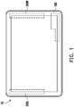
- FIG. 1 is a schematic front view illustrating a portable electronic device according to an embodiment of the disclosure.
- FIG. 2 is a flowchart illustrating a design method of an extension system of a woofer of the disclosure.
- the design method of the extension system of the woofer is adapted for a portable electronic device.
- the tablet computer has a body 10 and a speaker module disposed inside the body 10.
- the speaker module includes an extension system 100 of the woofer, a left channel speaker system 200L and a right channel speaker system 200R.
- the left channel speaker system 200L and the right channel speaker system 200R are as taught in the known art and handle sounds at medium and high frequencies. Therefore, details in this regard will not be further described in the following.
- the portable electronic device is limited of its inner space for disposing the woofer.
- the specific characteristic (the design method) according to the embodiments of the disclosure is needed.
- a predetermined space for installing the extension system 100 of the woofer to the portable electronic device is obtained.
- a cut-off frequency for the predetermined space is computed based on a wave formula of plane waves.
- the cut-off frequency is a resonance frequency of desired woofer sounds.
- the cut-off frequency is greater than or equal to 250 Hz. Accordingly, a channel size, i.e., the length and the cross-sectional area of the channel, for transmission of the woofer sounds is obtained at Step S130.
- a volume of a rear channel of the woofer may be set by obtaining the specification of the woofer. Then, at Step S160, the channel size is applied to a front channel of the extension system, and the channel size and the volume of the rear channel are fit together into the body 10 of the portable electronic device. Meanwhile, a bass hole of the front channel is formed on a surface of the body 10, and a space where the rear channel is located is a sealed space. Accordingly, the extension system 100 of the woofer of the embodiment is completed. It should be noted that the fitting process refers to a process adapted to cope with differences in configuration conditions (e.g., the internal space and peripheral components of the body 10) in the body 10.
- the embodiments of the disclosure use the wave formula of plane waves and peripheral setting conditions thereof instead. Therefore, the woofer is freed from a rear channel with a greater volume (thickness) required in the known art (e.g., those adopting a vented port) to transmit woofer sounds. Therefore, the embodiments of the disclosure are able to provide a woofer sound effect under a limited space condition in a thin electronic device.
- f p [(2m+1) ⁇ C]/4L, wherein f p represents low-frequency resonant frequency, C represents sound speed (in the unit of m/s), L represents length of a waveguide tube, which may be considered as a channel length or a distance that the woofer sound is transmitted from the speaker to an audio out.
- m 0, 1, 2, ..., represents mode of vibration.
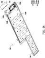
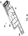
- FIGs. 3A to 3D and FIGs. 4A and 4D are different extension systems obtained according to the design method.
- the extension system 100 of the woofer disposed in the body 10 includes a woofer 110, a front channel F1, and a rear channel R1.
- the front channel F1 and the rear channel R1 are defined on the basis of the woofer 110.
- the front channel F1 is adapted to directly transmit sounds (acoustic waves) generated by the woofer 110, and the front channel F1 has a bass hole 140 formed on the surface of the body 10 to transmit the sound generated by the woofer 110 out of the body 10.
- the rear channel R1 is a sealed space adapted for resonance of the acoustic waves generated by the woofer 110 and for the resonated acoustic waves to also be transmitted out of the body 10 through the front channel F1 and the bass hole 140.
- the rear channel R1 further includes a space 120A and a space 120B.
- the woofer 110 is disposed on a side of the space 120A, and the space 120A is located between the space 120B and the woofer 110.
- the front channel F1 includes a space 130A and a channel 130B.
- the woofer 110 intervenes between the space 120A and the space 130A, and the sounds generated by the woofer 110 and the sounds resonated in the rear channels R1 are transmitted out of the body 10 through the space 130A, the channel 130B, and the bass hole 140.
- the volume of the rear channel R1 depends on the specification of the woofer 110.
- the woofer 110 suitable for the embodiment includes those whose power is less than equal to 2 w and having dimensions (length ⁇ width) of 16 mm ⁇ 9 mm, 32 mm ⁇ 9 mm, or 34 mm ⁇ 11 mm. Accordingly, the rear channel R1 may achieve acoustic wave resonance with a smaller volume.
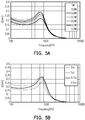
- FIG. 5A is a diagram illustrating a relation between diaphragm amplitude and power of a woofer.
- FIG. 5B is a diagram illustrating a relation between diaphragm amplitude and volume of a rear channel. Referring to FIGs.
- the diaphragm amplitude (when activated from 500 Hz to 700 Hz) of a woofer having the power of 1W may reach about 0.3 mm to 0.35 mm, and when the volume of the rear channel of the woofer whose power is 1W is set as 2 c.c, the resonated acoustic waves may render the diaphragm amplitude of the woofer to exceed 0.45 mm.
- the volume of the rear channel of the woofer whose power is 1w should be practically less than equal to 2 c.c, or the woofer may be damaged due to the diaphragm amplitude of the woofer exceeding its capability.
- the volume of the rear channel R1 of the embodiment after the setting at Step S140 and Step 150 should be less than 3 c.c.
- the volume of the rear channel corresponding to the dimensions (length ⁇ width) of 16 mm ⁇ 9 mm is 1 c.c
- the volume of the rear channel corresponding to the dimensions (length ⁇ width) of 32 mm ⁇ 9 mm is 2 c.c
- the volume of the rear channel corresponding to the dimensions (length ⁇ width) of 34 mm ⁇ 11 mm is 2 c.c.
- the volumes of the rear channel are upper limits.
- the woofer 110 whose dimensions (length ⁇ width) are 16 mm ⁇ 9 mm and whose thickness is 3 mm or 2.5 mm is described herein as an example, and the volume of the rear channel R1 may be set as 1 c.c.
- dimensions of the predetermined space obtained at Step S110 are 133.92 mm ⁇ 33 mm ⁇ 5.13 mm, and the thickness of 5.13 mm is described as an example based on the range that the thickness of the body 10 does not exceed 10 mm.
- the channel size obtained at Step 130 is that the channel length is 291.65 mm, and the channel cross-sectional area is 13 mm 2 .
- the channel 130B needs to be disposed in a bent arrangement, as shown in FIG. 3A , where the arrow signs indicate the transmission direction of the acoustic waves.
- an equivalent volume of the channel 130B of the front channel F1 is 3.53 c.c
- the volume of the space 130A is 0.18 c.c
- the volume of the front channel F1 formed accordingly is 3.71 c.c.
- the volume of the rear channel R1 is set at 1 c.c. Therefore, a total volume required by the extension system 100 of the woofer of the embodiment is 4.71 c.c, and the extension system 100 is able to be disposed in the body 10 of the portable electronic device based on the configuration shown in FIG. 3 .
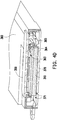
- FIGs. 3B and 3C are views illustrating structural configurations of the extension system 100 of the woofer from different perspectives
- FIG. 3D is a partial cross-sectional view of the extension system 100.
- the extension system 100 includes an upper case 160, a lower case 170, and a cover plate 150.
- the woofer 110 is accommodated in a space between the upper case 160 and the lower case 170 via an opening 163 of the upper case and covered by the cover plate 150.
- a space is kept between the cover plate 150 and the woofer 110.
- the upper case 160 includes a plurality of sub-spaces 161, 162, 164, and 165
- the lower case 170 correspondingly includes a plurality of sub-spaces 171 to 174.
- the sub-spaces 162 and 172 are combined to form the channel 130B
- the sub-spaces 161 and 171 are combined to form a portion of the space 130A
- the space between the cover plate 150 and the woofer 110 becomes another portion of the space 130A, as shown in FIG. 3D .
- the space 130A and the channel 130B may form the front channel F1.
- the sub-space 173 is located below the woofer 110, and the sub-space 146 and a portion of the sub-space 173 form the space 120A, as shown in FIG. 3D .
- the sub-space 174 and the sub-space 165 form the space 120B. Accordingly, the spaces 120A and 120B form the rear channel R1.
- a woofer 310 and the woofer 110 have the same specification, and a volume of a rear channel 320 is also set as 1 c.c, like the rear channel R1, but the configuration is different due to the predetermined space of 136.3mm ⁇ 31.3mm ⁇ 4.96mm.
- a volume of a space 330A obtained accordingly is 0.13 c.c
- a length and a cross-sectional area of a channel 330B are respectively 188.23 mm and 19.5 mm 2 . Therefore, an equivalent volume of the channel 330B is 2.8 c.c
- the channel 330B and the space 300A form the front channel.
- a total volume required by the extension system 300 of the woofer of the embodiment is 3.93 c.c
- the front channel (the space 300A and the channel 330B) and the rear channel are substantially located on the same plane.
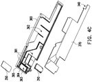
- FIGs. 4B and 4C are views illustrating structural configurations of the extension system 300 of the woofer from different perspectives
- FIG. 4D is a partial cross-sectional view of the extension system 300.
- the extension system 300 includes an upper case 360 and a lower case 370
- the woofer 310 is also disposed between the upper case 360 and the lower case 370 and correspond to an opening 363.
- a cover plate 350 covers openings 363 and 365, and a space is kept between the cover plate 350 and the woofer 310.
- the upper case 360 includes a plurality of sub-spaces 361 and 362, and the lower case 370 includes a plurality of sub-spaces 371 and 372 and a bass hole 340.
- the sub-spaces 372 and 362 form the channel 330B.
- sounds of the woofer 310 may be transmitted from a space corresponding to the opening 363 to a space corresponding to the opening 365 across the rib 364, as shown by arrow signs in FIG. 4D , so as to be from the space 340 to the channel 330B.
- the front channel is formed.
- the sub-spaces 371 and 361 form the space 320, i.e., the rear channel of the extension system.
- FIGs. 3A to 3D and FIGs. 4A to 4D shown above merely serve as examples of how the front channel is obtained and serves as the main structure of the extension system 300. However, such examples shall not be construed as limitations on the dimensions and modes of configuration of the extension system.
- FIG. 6A is a diagram illustrating a relation between frequency and impedance of an extension system.
- FIG. 6B is a diagram illustrating a relation between frequency and acoustic pressure of an extension system.
- a frequency response at 500 Hz or lower is obtained based on the specification of the front channel obtained according to the steps. Therefore, low frequency sounds are generated as expected.
- an acoustic pressure at a low frequency e.g., 500 Hz
- an acoustic pressure at a low frequency also achieves 70 dB or higher, indicating that acoustic waves are able to be transmitted out of the body 10.
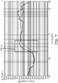
- FIG. 7 is a diagram illustrating a relation between frequency and acoustic pressure of an extension system.
- a darker curve in FIG. 7 represents the performance of the extension system 100 of the woofer as an example, and the other curve represents the performance of a known woofer system disposed in a portable electronic device.
- the extension system 100 of the woofer clearly exceeds the known woofer system by 10 dB or more.
- the extension system of the woofer designed according to the steps are able to certainly demonstrate a woofer sound effect.
- the predetermined space of the extension system of the woofer to be disposed in the electronic device is obtained.
- the cut-off frequency i.e., the woofer resonant frequency
- the channel length and the channel cross-sectional area of the extension system are further obtained through computation.
- the channel length and the channel cross-sectional area may form the front channel of the extension system in the body of the portable electronic device.
- the volume of the rear channel is obtained based on the specification of the woofer, wherein the volume of the front channel is greater than the volume of the rear channel.
- the extension system of the woofer may still be designed in a portable electronic device, such as a tablet computer, even when the device conditions (e.g., size and arrangement) of the portable electronic device are limited. In other words, even under a critical space usage condition inside the body, the extension system may still be disposed to allow the portable electronic device to play woofer sounds.
Landscapes
- Health & Medical Sciences (AREA)
- Otolaryngology (AREA)
- Physics & Mathematics (AREA)
- Engineering & Computer Science (AREA)
- Acoustics & Sound (AREA)
- Signal Processing (AREA)
- Obtaining Desirable Characteristics In Audible-Bandwidth Transducers (AREA)
- Details Of Audible-Bandwidth Transducers (AREA)
- Stereophonic System (AREA)
Applications Claiming Priority (1)
| Application Number | Priority Date | Filing Date | Title |
|---|---|---|---|
| TW107104379A TWI669967B (zh) | 2018-02-07 | 2018-02-07 | 低音揚聲器的擴展系統及其設計方法 |
Publications (1)
| Publication Number | Publication Date |
|---|---|
| EP3525480A1 true EP3525480A1 (de) | 2019-08-14 |
Family
ID=63207502
Family Applications (1)
| Application Number | Title | Priority Date | Filing Date |
|---|---|---|---|
| EP18185650.1A Withdrawn EP3525480A1 (de) | 2018-02-07 | 2018-07-26 | Erweiterungssystem von einem woofer und verfahren zu dessen entwurf |
Country Status (3)
| Country | Link |
|---|---|
| US (1) | US10645485B2 (de) |
| EP (1) | EP3525480A1 (de) |
| TW (1) | TWI669967B (de) |
Families Citing this family (2)
| Publication number | Priority date | Publication date | Assignee | Title |
|---|---|---|---|---|
| US11606633B2 (en) * | 2019-12-10 | 2023-03-14 | Apple Inc. | Speaker assembly |
| CN119031310A (zh) * | 2023-05-25 | 2024-11-26 | 荣耀终端有限公司 | 扬声器模组及电子设备 |
Citations (5)
| Publication number | Priority date | Publication date | Assignee | Title |
|---|---|---|---|---|
| JP2000050377A (ja) * | 1998-07-29 | 2000-02-18 | Nec Yonezawa Ltd | 携帯パソコン用拡張音響箱 |
| US20040240698A1 (en) * | 2003-05-30 | 2004-12-02 | Eaton William Chris | Reverse mounted micro-speaker assemblies and mobile terminals including the same |
| EP2282553A2 (de) * | 2009-07-27 | 2011-02-09 | Samsung Electronics Co., Ltd. | Basstonverstärkungshülle, Woofer damit und elektronische Vorrichtung mit dem Woofer |
| EP3242492A1 (de) * | 2016-05-02 | 2017-11-08 | Dolby International AB | Lautsprecher mit abgedichtetem rohr zur verbesserung eines niedrigen frequenzgangs in tragbaren vorrichtungen |
| US20180007465A1 (en) * | 2016-06-29 | 2018-01-04 | Acer Incorporated | Speaker having extended low frequency and electronic device using the same |
Family Cites Families (9)
| Publication number | Priority date | Publication date | Assignee | Title |
|---|---|---|---|---|
| CN1942020A (zh) | 2005-09-27 | 2007-04-04 | 精工爱普生株式会社 | 静电型超声波换能器及其设计方法、超声波扬声器 |
| CN101873771B (zh) | 2009-04-23 | 2013-04-17 | 宏达国际电子股份有限公司 | 可携式电子装置 |
| WO2012174611A1 (en) | 2011-06-22 | 2012-12-27 | Krix Loudspeakers Pty Ltd | Acoustic horn arrangement |
| CN102938869B (zh) * | 2012-11-27 | 2016-04-06 | 山东共达电声股份有限公司 | 利用前谐振腔实现小后腔微型扬声器系统低频响应的方法 |
| CN106134223B (zh) | 2014-11-13 | 2019-04-12 | 华为技术有限公司 | 重现双耳信号的音频信号处理设备和方法 |
| CN106714045B (zh) | 2015-08-13 | 2019-11-22 | 宏碁股份有限公司 | 扬声器与设有该扬声器的电子装置 |
| CN106658270A (zh) | 2015-11-03 | 2017-05-10 | 宏碁股份有限公司 | 扬声器音箱及应用该扬声器音箱的电子装置 |
| TW201801540A (zh) * | 2016-06-29 | 2018-01-01 | 宏碁股份有限公司 | 頻率延伸之揚聲器及應用其之電子裝置 |
| CN107147975B (zh) | 2017-04-26 | 2019-05-14 | 北京大学 | 一种面向不规则扬声器摆放的Ambisonics匹配投影解码方法 |
-
2018
- 2018-02-07 TW TW107104379A patent/TWI669967B/zh active
- 2018-05-27 US US15/990,678 patent/US10645485B2/en active Active
- 2018-07-26 EP EP18185650.1A patent/EP3525480A1/de not_active Withdrawn
Patent Citations (5)
| Publication number | Priority date | Publication date | Assignee | Title |
|---|---|---|---|---|
| JP2000050377A (ja) * | 1998-07-29 | 2000-02-18 | Nec Yonezawa Ltd | 携帯パソコン用拡張音響箱 |
| US20040240698A1 (en) * | 2003-05-30 | 2004-12-02 | Eaton William Chris | Reverse mounted micro-speaker assemblies and mobile terminals including the same |
| EP2282553A2 (de) * | 2009-07-27 | 2011-02-09 | Samsung Electronics Co., Ltd. | Basstonverstärkungshülle, Woofer damit und elektronische Vorrichtung mit dem Woofer |
| EP3242492A1 (de) * | 2016-05-02 | 2017-11-08 | Dolby International AB | Lautsprecher mit abgedichtetem rohr zur verbesserung eines niedrigen frequenzgangs in tragbaren vorrichtungen |
| US20180007465A1 (en) * | 2016-06-29 | 2018-01-04 | Acer Incorporated | Speaker having extended low frequency and electronic device using the same |
Also Published As
| Publication number | Publication date |
|---|---|
| TW201935938A (zh) | 2019-09-01 |
| US10645485B2 (en) | 2020-05-05 |
| US20190246200A1 (en) | 2019-08-08 |
| TWI669967B (zh) | 2019-08-21 |
Similar Documents
| Publication | Publication Date | Title |
|---|---|---|
| US10567868B2 (en) | Sound generator | |
| EP2910033B1 (de) | Resonanzdämpfung für audioüberträgersysteme | |
| US20250131905A1 (en) | Electronic device | |
| EP1401237B1 (de) | Asymmetrisches Lautsprechergehäuse mit verbessertem niedrigen Frequenzgang | |
| TW200803580A (en) | Electroacoustic transducer system and manufacturing method thereof | |
| US10368160B2 (en) | Speaker box | |
| CN109040926B (zh) | 发声器件及便携终端 | |
| CN1489362A (zh) | 用于包括有扬声器和耳机的无线通信终端的结构布置 | |
| US20160241950A1 (en) | Sound Transducer Acoustic Back Cavity System | |
| WO2020140548A1 (zh) | 发声器件及电子设备 | |
| CN108650603A (zh) | 发声器件及便携终端 | |
| CN111654778A (zh) | 电子设备、壳体组件以及电子设备的装配方法 | |
| US10645485B2 (en) | Extension system of woofer and design method thereof | |
| JP5152906B2 (ja) | 無指向性コンデンサーマイクロホンユニットおよび無指向性コンデンサーマイクロホン | |
| KR101534629B1 (ko) | 패널 가진형 스피커 | |
| CN221177908U (zh) | 电子设备 | |
| WO2021000104A1 (zh) | 扬声器箱 | |
| CN105764015B (zh) | 一种扬声器模组及移动终端 | |
| CN113114824A (zh) | 电子设备 | |
| CN222381769U (zh) | 一种耳机及耳机组件 | |
| CN218634207U (zh) | 一种具有防谐振峰的装置和耳机 | |
| US12289572B2 (en) | Electronic device with a sounding function | |
| CN114567841B (zh) | 发声装置和电子设备 | |
| CN116546400A (zh) | 电子设备 | |
| CN110225431A (zh) | 低音扬声器的扩展系统及其设计方法 |
Legal Events
| Date | Code | Title | Description |
|---|---|---|---|
| PUAI | Public reference made under article 153(3) epc to a published international application that has entered the european phase |
Free format text: ORIGINAL CODE: 0009012 |
|
| STAA | Information on the status of an ep patent application or granted ep patent |
Free format text: STATUS: THE APPLICATION HAS BEEN PUBLISHED |
|
| AK | Designated contracting states |
Kind code of ref document: A1 Designated state(s): AL AT BE BG CH CY CZ DE DK EE ES FI FR GB GR HR HU IE IS IT LI LT LU LV MC MK MT NL NO PL PT RO RS SE SI SK SM TR |
|
| AX | Request for extension of the european patent |
Extension state: BA ME |
|
| STAA | Information on the status of an ep patent application or granted ep patent |
Free format text: STATUS: REQUEST FOR EXAMINATION WAS MADE |
|
| 17P | Request for examination filed |
Effective date: 20191011 |
|
| RBV | Designated contracting states (corrected) |
Designated state(s): AL AT BE BG CH CY CZ DE DK EE ES FI FR GB GR HR HU IE IS IT LI LT LU LV MC MK MT NL NO PL PT RO RS SE SI SK SM TR |
|
| STAA | Information on the status of an ep patent application or granted ep patent |
Free format text: STATUS: EXAMINATION IS IN PROGRESS |
|
| 17Q | First examination report despatched |
Effective date: 20200108 |
|
| STAA | Information on the status of an ep patent application or granted ep patent |
Free format text: STATUS: THE APPLICATION IS DEEMED TO BE WITHDRAWN |
|
| 18D | Application deemed to be withdrawn |
Effective date: 20201014 |