EP2282789B1 - Vorrichtung zur unterstützung des herzens - Google Patents
Vorrichtung zur unterstützung des herzens Download PDFInfo
- Publication number
- EP2282789B1 EP2282789B1 EP08719062.5A EP08719062A EP2282789B1 EP 2282789 B1 EP2282789 B1 EP 2282789B1 EP 08719062 A EP08719062 A EP 08719062A EP 2282789 B1 EP2282789 B1 EP 2282789B1
- Authority
- EP
- European Patent Office
- Prior art keywords
- pump
- ports
- housing
- interior space
- heart
- Prior art date
- Legal status (The legal status is an assumption and is not a legal conclusion. Google has not performed a legal analysis and makes no representation as to the accuracy of the status listed.)
- Not-in-force
Links
Images



Classifications
-
- A—HUMAN NECESSITIES
- A61—MEDICAL OR VETERINARY SCIENCE; HYGIENE
- A61M—DEVICES FOR INTRODUCING MEDIA INTO, OR ONTO, THE BODY; DEVICES FOR TRANSDUCING BODY MEDIA OR FOR TAKING MEDIA FROM THE BODY; DEVICES FOR PRODUCING OR ENDING SLEEP OR STUPOR
- A61M60/00—Blood pumps; Devices for mechanical circulatory actuation; Balloon pumps for circulatory assistance
- A61M60/20—Type thereof
- A61M60/247—Positive displacement blood pumps
- A61M60/253—Positive displacement blood pumps including a displacement member directly acting on the blood
- A61M60/268—Positive displacement blood pumps including a displacement member directly acting on the blood the displacement member being flexible, e.g. membranes, diaphragms or bladders
- A61M60/274—Positive displacement blood pumps including a displacement member directly acting on the blood the displacement member being flexible, e.g. membranes, diaphragms or bladders the inlet and outlet being the same, e.g. para-aortic counter-pulsation blood pumps
-
- A—HUMAN NECESSITIES
- A61—MEDICAL OR VETERINARY SCIENCE; HYGIENE
- A61M—DEVICES FOR INTRODUCING MEDIA INTO, OR ONTO, THE BODY; DEVICES FOR TRANSDUCING BODY MEDIA OR FOR TAKING MEDIA FROM THE BODY; DEVICES FOR PRODUCING OR ENDING SLEEP OR STUPOR
- A61M60/00—Blood pumps; Devices for mechanical circulatory actuation; Balloon pumps for circulatory assistance
- A61M60/10—Location thereof with respect to the patient's body
- A61M60/122—Implantable pumps or pumping devices, i.e. the blood being pumped inside the patient's body
- A61M60/126—Implantable pumps or pumping devices, i.e. the blood being pumped inside the patient's body implantable via, into, inside, in line, branching on, or around a blood vessel
- A61M60/148—Implantable pumps or pumping devices, i.e. the blood being pumped inside the patient's body implantable via, into, inside, in line, branching on, or around a blood vessel in line with a blood vessel using resection or like techniques, e.g. permanent endovascular heart assist devices
-
- A—HUMAN NECESSITIES
- A61—MEDICAL OR VETERINARY SCIENCE; HYGIENE
- A61M—DEVICES FOR INTRODUCING MEDIA INTO, OR ONTO, THE BODY; DEVICES FOR TRANSDUCING BODY MEDIA OR FOR TAKING MEDIA FROM THE BODY; DEVICES FOR PRODUCING OR ENDING SLEEP OR STUPOR
- A61M60/00—Blood pumps; Devices for mechanical circulatory actuation; Balloon pumps for circulatory assistance
- A61M60/10—Location thereof with respect to the patient's body
- A61M60/122—Implantable pumps or pumping devices, i.e. the blood being pumped inside the patient's body
- A61M60/165—Implantable pumps or pumping devices, i.e. the blood being pumped inside the patient's body implantable in, on, or around the heart
- A61M60/178—Implantable pumps or pumping devices, i.e. the blood being pumped inside the patient's body implantable in, on, or around the heart drawing blood from a ventricle and returning the blood to the arterial system via a cannula external to the ventricle, e.g. left or right ventricular assist devices
-
- A—HUMAN NECESSITIES
- A61—MEDICAL OR VETERINARY SCIENCE; HYGIENE
- A61M—DEVICES FOR INTRODUCING MEDIA INTO, OR ONTO, THE BODY; DEVICES FOR TRANSDUCING BODY MEDIA OR FOR TAKING MEDIA FROM THE BODY; DEVICES FOR PRODUCING OR ENDING SLEEP OR STUPOR
- A61M60/00—Blood pumps; Devices for mechanical circulatory actuation; Balloon pumps for circulatory assistance
- A61M60/20—Type thereof
- A61M60/247—Positive displacement blood pumps
- A61M60/253—Positive displacement blood pumps including a displacement member directly acting on the blood
- A61M60/268—Positive displacement blood pumps including a displacement member directly acting on the blood the displacement member being flexible, e.g. membranes, diaphragms or bladders
-
- A—HUMAN NECESSITIES
- A61—MEDICAL OR VETERINARY SCIENCE; HYGIENE
- A61M—DEVICES FOR INTRODUCING MEDIA INTO, OR ONTO, THE BODY; DEVICES FOR TRANSDUCING BODY MEDIA OR FOR TAKING MEDIA FROM THE BODY; DEVICES FOR PRODUCING OR ENDING SLEEP OR STUPOR
- A61M60/00—Blood pumps; Devices for mechanical circulatory actuation; Balloon pumps for circulatory assistance
- A61M60/40—Details relating to driving
- A61M60/424—Details relating to driving for positive displacement blood pumps
- A61M60/438—Details relating to driving for positive displacement blood pumps the force acting on the blood contacting member being mechanical
- A61M60/454—Details relating to driving for positive displacement blood pumps the force acting on the blood contacting member being mechanical generated by electro-active actuators, e.g. using electro-active polymers or piezoelectric elements
-
- A—HUMAN NECESSITIES
- A61—MEDICAL OR VETERINARY SCIENCE; HYGIENE
- A61M—DEVICES FOR INTRODUCING MEDIA INTO, OR ONTO, THE BODY; DEVICES FOR TRANSDUCING BODY MEDIA OR FOR TAKING MEDIA FROM THE BODY; DEVICES FOR PRODUCING OR ENDING SLEEP OR STUPOR
- A61M60/00—Blood pumps; Devices for mechanical circulatory actuation; Balloon pumps for circulatory assistance
- A61M60/50—Details relating to control
- A61M60/508—Electronic control means, e.g. for feedback regulation
- A61M60/515—Regulation using real-time patient data
-
- A—HUMAN NECESSITIES
- A61—MEDICAL OR VETERINARY SCIENCE; HYGIENE
- A61M—DEVICES FOR INTRODUCING MEDIA INTO, OR ONTO, THE BODY; DEVICES FOR TRANSDUCING BODY MEDIA OR FOR TAKING MEDIA FROM THE BODY; DEVICES FOR PRODUCING OR ENDING SLEEP OR STUPOR
- A61M60/00—Blood pumps; Devices for mechanical circulatory actuation; Balloon pumps for circulatory assistance
- A61M60/80—Constructional details other than related to driving
- A61M60/855—Constructional details other than related to driving of implantable pumps or pumping devices
- A61M60/861—Connections or anchorings for connecting or anchoring pumps or pumping devices to parts of the patient's body
-
- A—HUMAN NECESSITIES
- A61—MEDICAL OR VETERINARY SCIENCE; HYGIENE
- A61M—DEVICES FOR INTRODUCING MEDIA INTO, OR ONTO, THE BODY; DEVICES FOR TRANSDUCING BODY MEDIA OR FOR TAKING MEDIA FROM THE BODY; DEVICES FOR PRODUCING OR ENDING SLEEP OR STUPOR
- A61M60/00—Blood pumps; Devices for mechanical circulatory actuation; Balloon pumps for circulatory assistance
- A61M60/80—Constructional details other than related to driving
- A61M60/855—Constructional details other than related to driving of implantable pumps or pumping devices
- A61M60/89—Valves
- A61M60/898—Valves the blood pump being a membrane blood pump and the membrane acting as inlet valve
Definitions
- the present invention relates to a heart assist device and more particularly, though not necessarily, to an improved implantable left ventricular assist device.
- a ventricular assist device is a mechanical device used to help either one or both ventricles of the heart to pump blood.
- VADs are designed to assist either the right (RVAD) or left (LVAD) ventricle, or both at once (BVAD).
- RVAD right
- LVAD left
- BVAD at once
- VAD pump In early procedures, the VAD pump was placed outside the body. More recently, the most commonly used VADs comprise an integrated pump and are implanted during open or closed -heart surgery, with a control line passing through the skin to a body worn controller. The use of implanted VADs with integrated pumps improves patient mobility and therefore a patient's capacity to lead a near normal life outside hospital.
- VADs make use of continuous-flow impeller pumps whose only moving part is a rotor. These are relatively small, easy to insert, and are expected to be reasonably durable. They are considered capable of maintaining adequate circulation, although their capability to fully unload the ventricle is questionable. Furthermore, the use of these pumps requires full anticoagulation therapy coupled with antiplatelet medication and there is a risk of bleeding and/or thromboembolic complications partly caused by the very small clearance of the rotor inside the device.
- VADs make use of centrifugal pumps in which the rotor is magnetically or mechanically suspended and, therefore, does not use ball bearings. This feature, coupled with the lower number of revolutions per minute, should provide enhanced durability. However, such VADs may also present a risk of complications including thromboembolic complications.
- VADs Up until recently, the most commonly used VADs however are pulsatile devices that mimic the natural pulsing action of the heart. These pulsatile devices use positive displacement pumps with pusher plates and inflow and outflow valves. These devices are efficient at unloading the ventricle which could help recovery of the native heart while maintaining circulation. Pulsatile devices do, however, have several disadvantages, such as their large size and complexity, which can increase the risk associated with insertion, predispose the patient to infection, and compress adjacent organs. They may also contain many moving parts that can affect their durability.
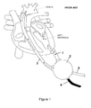
- Figure 1 illustrates prior art pulsatile type LVAD in situ.
- An inflow tube 1 is inserted into the apex of the left ventricle.
- blood passes through the inflow tube 1 to a pump within the device housing 2 and then out of the pump through an outflow tube 3 to the aorta.
- One-way valves are associated with the inflow and outflow tubes to prevent blood from flowing back from the aorta into the housing 2, or from the housing 2 to the ventricle, during the pumping action of the device.
- a lead 4 extends from the device, through the patient's skin, connecting the device to a power supply and to a control computer, both worn externally by the patient.
- the LVAD of Figure 1 receives a flow of blood from the left ventricle, traps this, and pushes it out to the aorta.
- This requires a relatively powerful pump comprising large pusher plates.
- This in turn requires venting of the outer sides of the pusher plates to the open air, requiring a venting tube 5 passing through the skin. Without this venting the displacement pumps would consume excessive power, as they would have to displace the pusher plates against a vacuum.
- LVADs Whilst conventional LVADs can provide significant therapeutic benefits, they may also give rise to complications including infection, immunosuppression, clotting with resultant stroke, and bleeding secondary to anticoagulation.
- complications including infection, immunosuppression, clotting with resultant stroke, and bleeding secondary to anticoagulation.
- the use of anti-coagulants then leads to an increased risk of bleeding.
- the design of existing commonly used VADs suffers from a number of other weaknesses.
- the implantable devices are generally large (in the region of 120cc in volume) and heavy and usually require open-heart surgery for implantation with the associated risks. Their large size also prevents these devices from being placed within the chest cavity, due to lack of space, so that they are usually positioned in the stomach area, making it necessary to use a more powerful pump given the increased distance over which the blood is required to travel.
- LVADs in conjunction with an appropriate drug therapy, can potentially lead to recovery of the patient without the need for further, more drastic treatment. It would be desirable to use LVADs in a greater number of patients. However, the risks associated with open heart surgery, as required to implant the existing LVADs, and with other complications is too great for those patients with less severe heart conditions. In addition, the size of existing devices mean that they are only suitable for use in patients weighing more than around 70kg, preventing their use in small adults or children. A smaller and more reliable LVAD that could be implanted using less invasive techniques would likely increase the use of LVADs.
- WO 2000/076288 discloses a different approach to assisting the heart and makes use of an inflatable cuff around the aorta. Inflating the cuff contracts the aorta and deflating the cuff allows the aorta to expand - in effect the aorta becomes a second left ventricle.
- the device described has potential advantages in avoiding the need to operate on the heart itself and in avoiding any contact between blood and the device. However this method poses a potentially significant risk of damage to the tissue of the aorta and histological changes have been observed in the outer wall of the aorta during animal and early clinical trials of such a device.
- US3553736 discloses an artificial auxiliary ventricle, and is considered the prior art closest to the subject matter of the present invention.
- the tubes used to route the bloodflow into the main chamber are not curving across each other, so that the entry and exit point of the blood in the aorta are substantially offset from each other.
- a ventricular assist device comprising a housing (6) defining a substantially cylindrical interior space, at least two ports (9,10) opening into said interior space at substantially diametrically opposed locations, and at least one pump (11,12) for pumping blood between the ports through said interior space, the ports and interior space providing a continuous blood flow path that is not interrupted by valves, wherein each port comprises a curved, hollow tube (7,8) that substantially retains its shape in situ and that follows a curvature of a curved interior surface of the housing, and in that the direction of curvature of said ports is substantially opposite, and said ports (9,10) open into said interior space at axially spaced locations to thereby encourage a smooth helical passage of blood without stasis or turbulence, wherein the tubes forming the ports curve across one another so that the ends of the tubes remote from the housing face in opposite directions.
- Embodiments of the present invention provide a failsafe mechanism providing an "open circuit" joined to the main aorta as the device does not restrict blood flow from the heart into the arterial system. They also reduce the complexity and number of components required in the device leading to a reduction in the size and cost of manufacture as well as a reduction in the number of potential points of failure.
- Said ports open into said interior space substantially tangentially to the inner surface of the housing defining the inner space.
- the configuration of the ports including their curvature and different planes of entry and exit into the housing, helps achieve a smooth helical passage of blood without stasis or turbulence. In addition this helical pattern of flow blends with that in the aorta.
- Embodiments of the present invention reduce the risk of some of the complications usually associated with VADs.
- the shape of the device ensures that blood within it "swirls" into and out of the device, allowing for a smooth continuous flow pattern and avoiding stagnant areas where clotting may occur. As a consequence, this reduces the need for anticoagulation therapy and therefore the risk of bleeding.
- the device comprises a pair of pumps for pumping blood between the ports through said interior space, each pump comprising a pusher plate disposed at an end surface of the interior space.
- each pump comprises a driving device disposed between the pusher plate and an inner surface of the housing.
- Embodiments of the present invention provide for increased pumping capacity. They also provide a fail-safe in so far as should one pump fail the other can still provide assistance. In addition, a second pump could compensate for a first pump that has failed.
- the driving device can comprise a linear oscillator actuator or an electroactive polymer material.
- Embodiments of the present invention using of electroactive polymer materials avoids the requirement for separate actuator motors, further reducing size and power requirements of the device.
- the device comprises a flexible diaphragm coupling the edge of the or each pusher plate to an interior of the housing.
- the device is configured to fit within the chest cavity of a patient, adjacent to the heart with a first of said curved, hollow tubes grafted to a posterolateral section of the ascending aorta and a second of the curved, hollow tubes grafted to an auterolateral section of the ascending aorta or to the aortic arch.
- Embodiments of the present invention enable the device to make use of the action of the aortic valve to prevent back-flow into the ventricle and removing the need for artificial valves, around which there is a significant risk of clotting as well as a problem of durability.
- the small amount of reverse flow that does occur is directed into the coronary arteries by the aortic valve, significantly enhancing the natural flow of blood into the coronary arteries.
- Embodiments of the present invention also allow it to take full advantage of the initial momentum provided by the pumping of the heart, even if only provided by a weak heart, such that a smaller, less powerful pump can be used to achieve similar performance as the known alternatives.
- the reduced size of the device provides the possibility of insertion using mini-invasive endoscopic techniques, eliminating the need for heart surgery and therefore reducing the risks associated with implantation.
- a ventricular assist system comprising a device according to any one of the preceding embodiments, a power supply coupled to the or each pump and a controller for synchronising the operation of the or each pump to the phases of the heart.
- said controller causing the or each pump to counter-pulsate with respect to the left ventricle.
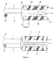
- FIG. 2 shows a LVAD comprising left and right side plates secured together with an airtight seal to form a generally hollow cylindrical housing 6.
- Each of the side plates is connected to or formed integrally with a curved hollow tube 7, 8.
- the side plates forming the housing, and the tubes, are made from a durable, biocompatible material such as titanium or moulded polyurethane.
- the hollow interior of the housing can have a volume in the region of 60cc to 80cc and the internal diameter of the tubes can be around 10 to 14 mm.
- each pump comprises a generally circular pusher-plate 13,14 that is driven by a linear oscillatory actuator (LOA) 15, 16, an example of which is given in US10/309,045 .
- LOA linear oscillatory actuator
- the pusher-plates are made from a durable, biocompatible material such as titanium or moulded polyurethane.
- the edges of the pusher-plates are connected to the housing by a flexible annular diaphragm 17, 18 made from a durable, biocompatible material such as segmented polyurethane.
- the two pumps 11,12 have an approximate combined capacity in the range of 20cc to 50cc and are powered and controlled by an external power source and computer as described below. The operation of the device will now be described.
- Figure 5 illustrates the device described above grafted onto the ascending aorta of the heart.
- the descending port 9 is grafted closest to the heart, into the posterolateral lower section of the aorta adjacent to the aortic valve, but above the coronary arteries.
- the ascending port 10 is grafted onto the auterolateral section on the right hand side of the aorta where it curves into the aortic arch.
- the location of the device and the eccentricity of the ascending and descending ports enables the flow from the device to follow and enhance the normal helical flow within the ascending aorta and provides a continuous flow pattern with no areas of stasis.
- a power and control line 20 extends from the device 19, through the patient's skin, connecting the device to a power supply and to a control computer 21, both worn externally by the patient.
- the power supply could make use of a Transcutaneous Energy Transfer System (TETS).
- TETS Transcutaneous Energy Transfer System
- the power supply and controller could potentially be fully integrated into the device allowing for total implantation of the system.
- the control computer 21 is coupled to ECG sensors 22 and is thereby able to detect the patient's heartbeats.
- the control computer uses these signals to synchronise the pumps to the contraction and expansion of the left ventricle. More particularly, the control computer detects the beginning of each QRS complex (see Figure 6 ) and actuates the pumps accordingly.
- the control computer may use pressure measurements (pressure sensing devices using Surface Acoustic Wave (SAW) and Micro-Electro-Mechanical Systems (MEMS) technology are under development) or the audible sound of the heart (i.e the particular noise made by the shutting of the aortic valve) or of blood flowing in the arteries to control the pumps.
- SAW Surface Acoustic Wave
- MEMS Micro-Electro-Mechanical Systems
- the filling of the device 19 may be assisted by the active withdrawal by the linear actuators of the pusher plates 13,14 under the control of the control computer, therefore reducing the pressure and resistance to the emptying of the natural heart, or applying suction, within the housing 6 and thus reducing any resistance to filling that may occur.
- the aortic valve then shuts and the heart enters the ventricular diastole phase.
- the control computer causes the linear actuators to drive the pusher-plates 13,14 into the interior of the housing 6, reducing the available volume and forcing blood out through the tubes 7,8 and out of the ports 9,10.
- Due to the shape of the device 19 the blood flow within the housing 6 follows a generally helical path, with the initial momentum of the blood within the device 19 being provided by the pumping action of the heart.
- the action of the pusher plates 13,14 causes the majority of blood within the device to follow this helical path out of the device 19, away from the heart and through the ascending port 10.
- a small volume of blood will also flow in the reverse direction i.e. out through the descending port 9, back towards the heart ( Figure 7 ).
- the aortic valve is shut during ventricular diastole, this reverse flow is directed into the coronary arteries resulting in an increased flow through the arteries and enhanced perfusion of the muscle tissue of the heart.
- the device provides a second beat during the ventricular diastole phase that assists the blood flow in the arterial system: it can be described as a counter pulsating device, pulsing out of phase with the beat of the heart.
- the cycle is repeated at a frequency dependent upon the patient's requirements, i.e. the cycle can repeat each time the heart beats or on every second or third beat.
- the amount of assist or volume of blood pumped by the device can be varied.
- control computer 21 worn externally by the patient controls aspects of the pumping action of the device as has been described.
- control computer can potentially make use of sensors disposed within the device to measure the rates of blood flow into and out of the device in order to adapt the device performance to that of the heart.
- the device described reduces the risk of some of the complications usually associated with LVADs.
- the shape of the device ensures that blood within it "swirls" into and out of the device, allowing for a smooth continuous flow pattern and avoiding stagnant areas where clotting may occur. As a consequence, this reduces the need for anticoagulation therapy and therefore the risk of bleeding.
- the valve-less mechanism is essentially a failsafe mechanism providing an "open circuit" joined to the main aorta. If there is a fault with the device, e.g. a power or sensor failure, the device does not restrict blood flow from the heart into the arterial system.
- the valve-less mechanism also reduces the complexity and number of components required in the device leading to a reduction in the size and cost of manufacture as well as a reduction in the number of potential points of failure.
- the valve-less design and the intended location of the device also significantly enhance the natural flow of blood into the coronary arteries, as a result of the small amount of reverse flow that occurs.
- blood will still flow through the device without the action of the pump, allowing this natural blood flow to wash out the pump volume and providing a further mechanism for reducing the risk of thrombosis.
- control computer could be programmed to enhance the action of the functioning pump, i.e. increasing the frequency at which the pump is activated, to compensate for the pump which has failed.
- dual pumps provide for increased pumping capacity.
- the device described above could be used in a greater number of patients than existing devices, such as children and small adults, as well as those patients with less severe heart conditions.
- the device can act as a 'bridge to recovery', providing sufficient support to the heart to potentially allow it to recover, without incurring the same level of risk as incurred by existing device.
- the pump can make use of pusher-plates made of an artificial muscle material that is driven by electrical stimulation.
- An example of an electroactive polymer actuator for use as a small-sized diaphragm pump is given in EP1323925 .
Landscapes
- Health & Medical Sciences (AREA)
- Heart & Thoracic Surgery (AREA)
- Engineering & Computer Science (AREA)
- Cardiology (AREA)
- Life Sciences & Earth Sciences (AREA)
- Anesthesiology (AREA)
- Biomedical Technology (AREA)
- Hematology (AREA)
- Mechanical Engineering (AREA)
- Animal Behavior & Ethology (AREA)
- General Health & Medical Sciences (AREA)
- Public Health (AREA)
- Veterinary Medicine (AREA)
- Vascular Medicine (AREA)
- Medical Informatics (AREA)
- External Artificial Organs (AREA)
Claims (10)
- Ventrikuläre Hilfsvorrichtung, die aufweist: ein Gehäuse (6), das einen im Wesentlichen zylindrischen Innenraum definiert; mindestens zwei Öffnungen (9, 10), die sich in den Innenraum an im Wesentlichen diametral gegenüberliegenden Stellen öffnen; und mindestens eine Pumpe (11, 12) für das Pumpen von Blut zwischen den Öffnungen durch den Innenraum, wobei die Öffnungen und der Innenraum einen kontinuierlichen Blutströmungsweg liefern, der nicht durch Ventile unterbrochen wird, wobei eine jede Öffnung einen gebogenen, hohlen Schlauch (7, 8) aufweist, der im Wesentlichen seine Form an Ort und Stelle beibehält, und der einer Krümmung einer gebogenen Innenfläche des Gehäuses folgt, und wobei die Richtung der Krümmung der Öffnungen im Wesentlichen entgegengesetzt ist, und wobei sich die Öffnungen (9, 10) in den Innenraum an axial beabstandeten Stellen öffnen, um dadurch einen gleichmäßigen schraubenförmigen Durchgang des Blutes ohne Stase oder Turbulenz zu unterstützen, dadurch gekennzeichnet, dass
die Schläuche, die die Öffnungen bilden, sich übereinander krümmen, so dass die Enden der Schläuche entfernt vom Gehäuse in entgegengesetzten Richtungen liegen. - Vorrichtung nach Anspruch 1 und die ein Paar Pumpen (11, 12) für das Pumpen von Blut zwischen den Öffnungen (9, 10) durch den Innenraum aufweist, wobei eine jede Pumpe eine Schieberplatte (13, 14) aufweist, die an einer Endfläche des Innenraumes angeordnet ist.
- Vorrichtung nach Anspruch 2, wobei eine jede Pumpe (11, 12) eine Antriebsvorrichtung (15, 16) aufweist, die zwischen der Schieberplatte (13, 14) und einer Innenfläche des Gehäuses angeordnet ist.
- Vorrichtung nach Anspruch 3, bei der die Antriebsvorrichtung (15, 16) ein lineares Oszillatorbetätigungselement aufweist.
- Vorrichtung nach Anspruch 2, bei der die oder jede Schieberplatte (15, 16) ein elektroaktives Polymermaterial aufweist.
- Vorrichtung nach einem der Ansprüche 2 bis 5, und die ein flexibles Diaphragma (17, 18) aufweist, das den Rand der oder einer jeden Schieberplatte (15, 16) mit einer Innenseite des Gehäuses verbindet.
- Vorrichtung nach einem der vorhergehenden Ansprüche und ausgebildet, um innerhalb des Brustkastens eines Patienten benachbart dem Herzen zu passen.
- Vorrichtung nach Anspruch 7 und so ausgebildet, dass ein erster der gebogenen, hohlen Schläuche (7, 8) auf einen posterolateralen Abschnitt der aufsteigenden Aorta und ein zweiter der gebogenen, hohlen Schläuche (7, 8) auf einen anterolateralen Abschnitt der aufsteigenden Aorta oder auf den Aortenbogen transplantiert werden kann.
- Ventrikuläres Hilfssystem, das aufweist:eine Vorrichtung (19) nach einem der vorhergehenden Ansprüche;eine Stromversorgung (21), die mit der oder jeder Pumpe verbunden ist; undeinen Regler (21) für das Synchronisieren der Funktion der oder jeder Pumpe (11, 12) mit den Phasen des Herzens.
- System nach Anspruch 9, wobei der Regler (21) bewirkt, dass die oder jede Pumpe (11, 12) mit Bezugnahme auf die linke Kammer gegenpulsiert.
Applications Claiming Priority (1)
| Application Number | Priority Date | Filing Date | Title |
|---|---|---|---|
| PCT/GB2008/050217 WO2009118499A1 (en) | 2008-03-26 | 2008-03-26 | Heart assist device |
Publications (2)
| Publication Number | Publication Date |
|---|---|
| EP2282789A1 EP2282789A1 (de) | 2011-02-16 |
| EP2282789B1 true EP2282789B1 (de) | 2015-09-09 |
Family
ID=40043002
Family Applications (1)
| Application Number | Title | Priority Date | Filing Date |
|---|---|---|---|
| EP08719062.5A Not-in-force EP2282789B1 (de) | 2008-03-26 | 2008-03-26 | Vorrichtung zur unterstützung des herzens |
Country Status (4)
| Country | Link |
|---|---|
| US (2) | US20110071337A1 (de) |
| EP (1) | EP2282789B1 (de) |
| JP (1) | JP2011515174A (de) |
| WO (1) | WO2009118499A1 (de) |
Families Citing this family (40)
| Publication number | Priority date | Publication date | Assignee | Title |
|---|---|---|---|---|
| EP2282789B1 (de) * | 2008-03-26 | 2015-09-09 | Heart Biotech Limited | Vorrichtung zur unterstützung des herzens |
| US9782527B2 (en) | 2009-05-27 | 2017-10-10 | Tc1 Llc | Monitoring of redundant conductors |
| US8562508B2 (en) | 2009-12-30 | 2013-10-22 | Thoratec Corporation | Mobility-enhancing blood pump system |
| US9089635B2 (en) | 2010-06-22 | 2015-07-28 | Thoratec Corporation | Apparatus and method for modifying pressure-flow characteristics of a pump |
| WO2012012552A1 (en) | 2010-07-22 | 2012-01-26 | Thoratec Corporation | Controlling implanted blood pumps |
| EP3248628B1 (de) | 2010-08-20 | 2019-01-02 | Tc1 Llc | Implantierbare blutpumpe |
| EP3117845B1 (de) | 2010-09-24 | 2018-10-31 | Tc1 Llc | Erzeugung eines künstlichen pulses |
| PL218244B1 (pl) * | 2011-02-28 | 2014-10-31 | Fundacja Rozwoju Kardiochirurgii Im Prof Zbigniewa Religi | Pompa krwi, zwłaszcza implantowalna pneumatyczna komora wspomagania serca |
| WO2014036410A1 (en) | 2012-08-31 | 2014-03-06 | Thoratec Corporation | Start-up algorithm for an implantable blood pump |
| US9492599B2 (en) | 2012-08-31 | 2016-11-15 | Thoratec Corporation | Hall sensor mounting in an implantable blood pump |
| CN107865988A (zh) * | 2013-03-15 | 2018-04-03 | 华思科公司 | 胸主动脉心室辅助系统 |
| US9320841B2 (en) * | 2013-06-21 | 2016-04-26 | Corvivo, Inc. | Ventricular assist device |
| EP3131600B1 (de) | 2014-04-15 | 2021-06-16 | Tc1 Llc | Verfahren und systeme zur bereitstellung von batteriefeedback an patienten |
| CN110101927B (zh) | 2014-04-15 | 2021-10-08 | Tc1有限责任公司 | 用于控制血泵的方法和系统 |
| US9744280B2 (en) | 2014-04-15 | 2017-08-29 | Tc1 Llc | Methods for LVAD operation during communication losses |
| EP3131598B1 (de) | 2014-04-15 | 2020-10-21 | Tc1 Llc | Systeme zur aufrüstung von ventrikulären unterstützungsvorrichtungen |
| WO2015160995A1 (en) | 2014-04-15 | 2015-10-22 | Thoratec Corporation | Ventricular assist devices |
| US10702641B2 (en) | 2015-06-29 | 2020-07-07 | Tc1 Llc | Ventricular assist devices having a hollow rotor and methods of use |
| WO2017015210A1 (en) | 2015-07-20 | 2017-01-26 | Thoratec Corporation | Strain gauge for flow estimation |
| WO2017015268A1 (en) | 2015-07-20 | 2017-01-26 | Thoratec Corporation | Flow estimation using hall-effect sensors |
| CN105597172B (zh) * | 2016-02-02 | 2017-12-08 | 丁以群 | 左心辅助装置 |
| EP4732889A2 (de) | 2017-06-07 | 2026-04-29 | Supira Medical, Inc. | Vorrichtungen, systeme und verfahren zur bewegung intravaskulärer flüssigkeiten |
| US11511103B2 (en) | 2017-11-13 | 2022-11-29 | Shifamed Holdings, Llc | Intravascular fluid movement devices, systems, and methods of use |
| US10973967B2 (en) | 2018-01-10 | 2021-04-13 | Tc1 Llc | Bearingless implantable blood pump |
| JP7410034B2 (ja) | 2018-02-01 | 2024-01-09 | シファメド・ホールディングス・エルエルシー | 血管内血液ポンプならびに使用および製造の方法 |
| US20210290934A1 (en) * | 2018-07-17 | 2021-09-23 | Viaderm Llc | Indwelling hyper-dimensional cardiac physiologic data logging and transmission system and method of doing business |
| WO2020028537A1 (en) | 2018-07-31 | 2020-02-06 | Shifamed Holdings, Llc | Intravascaular blood pumps and methods of use |
| WO2020073047A1 (en) | 2018-10-05 | 2020-04-09 | Shifamed Holdings, Llc | Intravascular blood pumps and methods of use |
| WO2021011473A1 (en) | 2019-07-12 | 2021-01-21 | Shifamed Holdings, Llc | Intravascular blood pumps and methods of manufacture and use |
| US11654275B2 (en) | 2019-07-22 | 2023-05-23 | Shifamed Holdings, Llc | Intravascular blood pumps with struts and methods of use and manufacture |
| EP4010046A4 (de) | 2019-08-07 | 2023-08-30 | Calomeni, Michael | Katheterblutpumpen und zusammenklappbare pumpengehäuse |
| WO2021062260A1 (en) | 2019-09-25 | 2021-04-01 | Shifamed Holdings, Llc | Catheter blood pumps and collapsible blood conduits |
| EP4034221B1 (de) | 2019-09-25 | 2024-11-13 | Shifamed Holdings, LLC | Katheterblutpumpen und zusammenklappbare pumpengehäuse |
| EP4034192B1 (de) | 2019-09-25 | 2025-12-24 | Supira Medical, Inc. | Intravaskuläre blutpumpensysteme und verfahren zur verwendung und steuerung davon |
| US20210113751A1 (en) * | 2019-10-17 | 2021-04-22 | Heartware, Inc. | Pulsatile blood pump with active element and thrombus rinse |
| EP4072650A4 (de) | 2019-12-11 | 2024-01-10 | Shifamed Holdings, LLC | Absteigende aorten- und hohlvenenblutpumpen |
| US12599758B2 (en) | 2019-12-19 | 2026-04-14 | Shifamed Holdings, Llc | Intravascular blood pumps, motors, and fluid control |
| US11534596B2 (en) | 2020-01-09 | 2022-12-27 | Heartware, Inc. | Pulsatile blood pump via contraction with smart material |
| EP4489837A1 (de) * | 2022-03-11 | 2025-01-15 | Phap Medical, LLC | Systeme und verfahren für eine peristalsis-herzunterstützungspumpe |
| CN117224830A (zh) * | 2023-09-25 | 2023-12-15 | 杭州晟视科技有限公司 | 膜泵组件及心脏辅助装置 |
Family Cites Families (34)
| Publication number | Priority date | Publication date | Assignee | Title |
|---|---|---|---|---|
| US3553736A (en) * | 1968-11-25 | 1971-01-12 | Us Health Education & Welfare | Auxiliary ventricle |
| US4195623A (en) * | 1977-07-21 | 1980-04-01 | Phillips Steven J | Parallel aorta balloon pump and method of using same |
| US4222127A (en) * | 1978-06-02 | 1980-09-16 | Donachy And Pierce | Blood pump and method of pumping blood |
| FR2591489B1 (fr) * | 1985-12-16 | 1988-03-25 | Aerospatiale | Prothese cardiaque totale comportant deux modules de pompage relies par une liaison fonctionnelle. |
| US4756302A (en) * | 1986-11-20 | 1988-07-12 | Novacor Medical Corporation | Blood pumping system and method |
| US4938766A (en) * | 1987-08-28 | 1990-07-03 | Jarvik Robert K | Prosthetic compliance devices |
| DE68923792T2 (de) * | 1988-12-29 | 1996-05-02 | Chang Ann Lois | Diaphragmapumpe. |
| US5477864A (en) * | 1989-12-21 | 1995-12-26 | Smith & Nephew Richards, Inc. | Cardiovascular guidewire of enhanced biocompatibility |
| JP2800585B2 (ja) * | 1991-09-30 | 1998-09-21 | 日本ゼオン株式会社 | 血液循環補助装置 |
| US5344385A (en) * | 1991-09-30 | 1994-09-06 | Thoratec Laboratories Corporation | Step-down skeletal muscle energy conversion system |
| US5443504A (en) * | 1991-09-30 | 1995-08-22 | Hill; John D. | Basic skeletal muscle energy conversion system |
| US5676651A (en) * | 1992-08-06 | 1997-10-14 | Electric Boat Corporation | Surgically implantable pump arrangement and method for pumping body fluids |
| US6610004B2 (en) * | 1997-10-09 | 2003-08-26 | Orqis Medical Corporation | Implantable heart assist system and method of applying same |
| US5980448A (en) * | 1998-01-28 | 1999-11-09 | Vascor, Inc. | Single chamber blood pump |
| AUPQ090499A0 (en) * | 1999-06-10 | 1999-07-01 | Peters, William S | Heart assist device and system |
| GB0023412D0 (en) * | 2000-09-23 | 2000-11-08 | Khaghani Asghar | Aortic counterpulsator |
| TW458771B (en) * | 2000-12-13 | 2001-10-11 | Jiang R Chung | Structure of blood-propelling cavity of artificial left ventricle |
| US7229402B2 (en) * | 2001-02-09 | 2007-06-12 | Cardiac Output Technologies, Inc. | Minimally invasive ventricular assist technology and method |
| US6632169B2 (en) * | 2001-03-13 | 2003-10-14 | Ltk Enterprises, L.L.C. | Optimized pulsatile-flow ventricular-assist device and total artificial heart |
| WO2003001980A2 (en) * | 2001-06-29 | 2003-01-09 | Medquest Products,Inc. | Cannulation apparatus and method |
| JP3832338B2 (ja) | 2001-12-25 | 2006-10-11 | 松下電工株式会社 | 電歪ポリマーアクチュエータ |
| JP3863429B2 (ja) * | 2002-01-04 | 2006-12-27 | 学校法人東京電機大学 | リニア振動アクチュエータ |
| US6695761B2 (en) * | 2002-01-30 | 2004-02-24 | Biomed Solutions, Llc | Apparatus for assisting a heart |
| AR036548A1 (es) * | 2002-09-18 | 2004-09-15 | Domingo Santo Liotta | Dispositivo de implante corporal para asistencia circulatoria sanguinea y ventricular cardiaca |
| US20040068224A1 (en) * | 2002-10-02 | 2004-04-08 | Couvillon Lucien Alfred | Electroactive polymer actuated medication infusion pumps |
| US7494459B2 (en) * | 2003-06-26 | 2009-02-24 | Biophan Technologies, Inc. | Sensor-equipped and algorithm-controlled direct mechanical ventricular assist device |
| LT1715902T (lt) * | 2004-01-08 | 2016-11-10 | Sullivan, Paul Joseph | Neišardomas fluido perdavimo įrenginys |
| US7588530B2 (en) * | 2004-07-19 | 2009-09-15 | Marlin Stephen Heilman | Devices, systems and methods for assisting blood flow |
| US20080045777A1 (en) * | 2005-06-09 | 2008-02-21 | Jal Jassawalla | Electromagnetic drive for a ventricular assist device |
| WO2006135822A2 (en) * | 2005-06-09 | 2006-12-21 | World Heart Corporation | Single sac ventricular assist device |
| US9144669B2 (en) * | 2005-11-16 | 2015-09-29 | Heartware, Inc. | Implantation procedure for blood pumps |
| WO2007089500A2 (en) * | 2006-01-30 | 2007-08-09 | Pong-Jeu Lu | Dual-pulsation bi-ventricular assist device |
| EP2282789B1 (de) * | 2008-03-26 | 2015-09-09 | Heart Biotech Limited | Vorrichtung zur unterstützung des herzens |
| US8372145B2 (en) * | 2009-05-19 | 2013-02-12 | Hisham M. F. SHERIF | Implantable artificial ventricle having low energy requirement |
-
2008
- 2008-03-26 EP EP08719062.5A patent/EP2282789B1/de not_active Not-in-force
- 2008-03-26 US US12/934,300 patent/US20110071337A1/en not_active Abandoned
- 2008-03-26 JP JP2011501282A patent/JP2011515174A/ja active Pending
- 2008-03-26 WO PCT/GB2008/050217 patent/WO2009118499A1/en not_active Ceased
-
2013
- 2013-04-04 US US13/856,809 patent/US9333284B2/en not_active Expired - Fee Related
Also Published As
| Publication number | Publication date |
|---|---|
| WO2009118499A1 (en) | 2009-10-01 |
| US20110071337A1 (en) | 2011-03-24 |
| EP2282789A1 (de) | 2011-02-16 |
| US9333284B2 (en) | 2016-05-10 |
| US20130289335A1 (en) | 2013-10-31 |
| JP2011515174A (ja) | 2011-05-19 |
Similar Documents
| Publication | Publication Date | Title |
|---|---|---|
| EP2282789B1 (de) | Vorrichtung zur unterstützung des herzens | |
| JP7623741B2 (ja) | 大動脈傍血液ポンプ装置 | |
| JP5182946B2 (ja) | 二重拍動式の両心室補助装置 | |
| EP2209508B1 (de) | Pulsierende blutpumpe | |
| JP2008207018A (ja) | 心臓補助デバイス | |
| CN102107030B (zh) | 心脏搏动辅助装置、心脏搏动辅助系统、以及治疗心力衰竭的方法 | |
| JP2008525077A (ja) | 血液循環補助装置 | |
| WO2014201575A1 (en) | Artificial ventricles | |
| JP7684904B2 (ja) | 圧力アンロード左心室補助装置およびヒト心臓を補助するための方法 | |
| CN201572358U (zh) | 心脏搏动辅助装置以及心脏搏动辅助系统 | |
| JP7650542B2 (ja) | 圧力センサを内蔵した心室補助装置 | |
| AU2022430007B2 (en) | Endo-leak free aortic adapter assembly and method of device delivery | |
| KR101105818B1 (ko) | 혈액펌프를 이용한 응급처치 장치 및 그 사용 방법 | |
| US20260041902A1 (en) | Pulsatile ventricular assist devices | |
| CN116997383A (zh) | 主动脉旁血泵装置 |
Legal Events
| Date | Code | Title | Description |
|---|---|---|---|
| PUAI | Public reference made under article 153(3) epc to a published international application that has entered the european phase |
Free format text: ORIGINAL CODE: 0009012 |
|
| 17P | Request for examination filed |
Effective date: 20101022 |
|
| AK | Designated contracting states |
Kind code of ref document: A1 Designated state(s): AT BE BG CH CY CZ DE DK EE ES FI FR GB GR HR HU IE IS IT LI LT LU LV MC MT NL NO PL PT RO SE SI SK TR |
|
| AX | Request for extension of the european patent |
Extension state: AL BA MK RS |
|
| DAX | Request for extension of the european patent (deleted) | ||
| 17Q | First examination report despatched |
Effective date: 20120731 |
|
| GRAP | Despatch of communication of intention to grant a patent |
Free format text: ORIGINAL CODE: EPIDOSNIGR1 |
|
| RIN1 | Information on inventor provided before grant (corrected) |
Inventor name: THOMPSON, RAYMOND Inventor name: YACOUB, MAGDI, HABIB |
|
| INTG | Intention to grant announced |
Effective date: 20150325 |
|
| GRAS | Grant fee paid |
Free format text: ORIGINAL CODE: EPIDOSNIGR3 |
|
| GRAA | (expected) grant |
Free format text: ORIGINAL CODE: 0009210 |
|
| RAP1 | Party data changed (applicant data changed or rights of an application transferred) |
Owner name: HEART BIOTECH LIMITED |
|
| AK | Designated contracting states |
Kind code of ref document: B1 Designated state(s): AT BE BG CH CY CZ DE DK EE ES FI FR GB GR HR HU IE IS IT LI LT LU LV MC MT NL NO PL PT RO SE SI SK TR |
|
| REG | Reference to a national code |
Ref country code: GB Ref legal event code: FG4D |
|
| REG | Reference to a national code |
Ref country code: AT Ref legal event code: REF Ref document number: 747579 Country of ref document: AT Kind code of ref document: T Effective date: 20150915 Ref country code: CH Ref legal event code: EP |
|
| REG | Reference to a national code |
Ref country code: IE Ref legal event code: FG4D |
|
| REG | Reference to a national code |
Ref country code: DE Ref legal event code: R096 Ref document number: 602008040068 Country of ref document: DE |
|
| REG | Reference to a national code |
Ref country code: NL Ref legal event code: MP Effective date: 20150909 |
|
| PG25 | Lapsed in a contracting state [announced via postgrant information from national office to epo] |
Ref country code: FI Free format text: LAPSE BECAUSE OF FAILURE TO SUBMIT A TRANSLATION OF THE DESCRIPTION OR TO PAY THE FEE WITHIN THE PRESCRIBED TIME-LIMIT Effective date: 20150909 Ref country code: GR Free format text: LAPSE BECAUSE OF FAILURE TO SUBMIT A TRANSLATION OF THE DESCRIPTION OR TO PAY THE FEE WITHIN THE PRESCRIBED TIME-LIMIT Effective date: 20151210 Ref country code: NO Free format text: LAPSE BECAUSE OF FAILURE TO SUBMIT A TRANSLATION OF THE DESCRIPTION OR TO PAY THE FEE WITHIN THE PRESCRIBED TIME-LIMIT Effective date: 20151209 Ref country code: LV Free format text: LAPSE BECAUSE OF FAILURE TO SUBMIT A TRANSLATION OF THE DESCRIPTION OR TO PAY THE FEE WITHIN THE PRESCRIBED TIME-LIMIT Effective date: 20150909 Ref country code: LT Free format text: LAPSE BECAUSE OF FAILURE TO SUBMIT A TRANSLATION OF THE DESCRIPTION OR TO PAY THE FEE WITHIN THE PRESCRIBED TIME-LIMIT Effective date: 20150909 |
|
| REG | Reference to a national code |
Ref country code: LT Ref legal event code: MG4D |
|
| REG | Reference to a national code |
Ref country code: AT Ref legal event code: MK05 Ref document number: 747579 Country of ref document: AT Kind code of ref document: T Effective date: 20150909 |
|
| PG25 | Lapsed in a contracting state [announced via postgrant information from national office to epo] |
Ref country code: ES Free format text: LAPSE BECAUSE OF FAILURE TO SUBMIT A TRANSLATION OF THE DESCRIPTION OR TO PAY THE FEE WITHIN THE PRESCRIBED TIME-LIMIT Effective date: 20150909 Ref country code: HR Free format text: LAPSE BECAUSE OF FAILURE TO SUBMIT A TRANSLATION OF THE DESCRIPTION OR TO PAY THE FEE WITHIN THE PRESCRIBED TIME-LIMIT Effective date: 20150909 Ref country code: SE Free format text: LAPSE BECAUSE OF FAILURE TO SUBMIT A TRANSLATION OF THE DESCRIPTION OR TO PAY THE FEE WITHIN THE PRESCRIBED TIME-LIMIT Effective date: 20150909 |
|
| PG25 | Lapsed in a contracting state [announced via postgrant information from national office to epo] |
Ref country code: NL Free format text: LAPSE BECAUSE OF FAILURE TO SUBMIT A TRANSLATION OF THE DESCRIPTION OR TO PAY THE FEE WITHIN THE PRESCRIBED TIME-LIMIT Effective date: 20150909 |
|
| PG25 | Lapsed in a contracting state [announced via postgrant information from national office to epo] |
Ref country code: SK Free format text: LAPSE BECAUSE OF FAILURE TO SUBMIT A TRANSLATION OF THE DESCRIPTION OR TO PAY THE FEE WITHIN THE PRESCRIBED TIME-LIMIT Effective date: 20150909 Ref country code: IS Free format text: LAPSE BECAUSE OF FAILURE TO SUBMIT A TRANSLATION OF THE DESCRIPTION OR TO PAY THE FEE WITHIN THE PRESCRIBED TIME-LIMIT Effective date: 20160109 Ref country code: CZ Free format text: LAPSE BECAUSE OF FAILURE TO SUBMIT A TRANSLATION OF THE DESCRIPTION OR TO PAY THE FEE WITHIN THE PRESCRIBED TIME-LIMIT Effective date: 20150909 Ref country code: EE Free format text: LAPSE BECAUSE OF FAILURE TO SUBMIT A TRANSLATION OF THE DESCRIPTION OR TO PAY THE FEE WITHIN THE PRESCRIBED TIME-LIMIT Effective date: 20150909 |
|
| REG | Reference to a national code |
Ref country code: FR Ref legal event code: PLFP Year of fee payment: 9 |
|
| PG25 | Lapsed in a contracting state [announced via postgrant information from national office to epo] |
Ref country code: PT Free format text: LAPSE BECAUSE OF FAILURE TO SUBMIT A TRANSLATION OF THE DESCRIPTION OR TO PAY THE FEE WITHIN THE PRESCRIBED TIME-LIMIT Effective date: 20160111 Ref country code: RO Free format text: LAPSE BECAUSE OF FAILURE TO SUBMIT A TRANSLATION OF THE DESCRIPTION OR TO PAY THE FEE WITHIN THE PRESCRIBED TIME-LIMIT Effective date: 20150909 Ref country code: AT Free format text: LAPSE BECAUSE OF FAILURE TO SUBMIT A TRANSLATION OF THE DESCRIPTION OR TO PAY THE FEE WITHIN THE PRESCRIBED TIME-LIMIT Effective date: 20150909 Ref country code: PL Free format text: LAPSE BECAUSE OF FAILURE TO SUBMIT A TRANSLATION OF THE DESCRIPTION OR TO PAY THE FEE WITHIN THE PRESCRIBED TIME-LIMIT Effective date: 20150909 |
|
| REG | Reference to a national code |
Ref country code: DE Ref legal event code: R097 Ref document number: 602008040068 Country of ref document: DE |
|
| PLBE | No opposition filed within time limit |
Free format text: ORIGINAL CODE: 0009261 |
|
| STAA | Information on the status of an ep patent application or granted ep patent |
Free format text: STATUS: NO OPPOSITION FILED WITHIN TIME LIMIT |
|
| 26N | No opposition filed |
Effective date: 20160610 |
|
| PG25 | Lapsed in a contracting state [announced via postgrant information from national office to epo] |
Ref country code: SI Free format text: LAPSE BECAUSE OF FAILURE TO SUBMIT A TRANSLATION OF THE DESCRIPTION OR TO PAY THE FEE WITHIN THE PRESCRIBED TIME-LIMIT Effective date: 20150909 Ref country code: DK Free format text: LAPSE BECAUSE OF FAILURE TO SUBMIT A TRANSLATION OF THE DESCRIPTION OR TO PAY THE FEE WITHIN THE PRESCRIBED TIME-LIMIT Effective date: 20150909 Ref country code: BE Free format text: LAPSE BECAUSE OF NON-PAYMENT OF DUE FEES Effective date: 20160331 |
|
| PG25 | Lapsed in a contracting state [announced via postgrant information from national office to epo] |
Ref country code: LU Free format text: LAPSE BECAUSE OF FAILURE TO SUBMIT A TRANSLATION OF THE DESCRIPTION OR TO PAY THE FEE WITHIN THE PRESCRIBED TIME-LIMIT Effective date: 20160326 Ref country code: MC Free format text: LAPSE BECAUSE OF FAILURE TO SUBMIT A TRANSLATION OF THE DESCRIPTION OR TO PAY THE FEE WITHIN THE PRESCRIBED TIME-LIMIT Effective date: 20150909 |
|
| REG | Reference to a national code |
Ref country code: CH Ref legal event code: PL |
|
| REG | Reference to a national code |
Ref country code: IE Ref legal event code: MM4A |
|
| PG25 | Lapsed in a contracting state [announced via postgrant information from national office to epo] |
Ref country code: BE Free format text: LAPSE BECAUSE OF FAILURE TO SUBMIT A TRANSLATION OF THE DESCRIPTION OR TO PAY THE FEE WITHIN THE PRESCRIBED TIME-LIMIT Effective date: 20150909 |
|
| PG25 | Lapsed in a contracting state [announced via postgrant information from national office to epo] |
Ref country code: CH Free format text: LAPSE BECAUSE OF NON-PAYMENT OF DUE FEES Effective date: 20160331 Ref country code: IE Free format text: LAPSE BECAUSE OF NON-PAYMENT OF DUE FEES Effective date: 20160326 Ref country code: LI Free format text: LAPSE BECAUSE OF NON-PAYMENT OF DUE FEES Effective date: 20160331 |
|
| REG | Reference to a national code |
Ref country code: FR Ref legal event code: PLFP Year of fee payment: 10 |
|
| PG25 | Lapsed in a contracting state [announced via postgrant information from national office to epo] |
Ref country code: MT Free format text: LAPSE BECAUSE OF FAILURE TO SUBMIT A TRANSLATION OF THE DESCRIPTION OR TO PAY THE FEE WITHIN THE PRESCRIBED TIME-LIMIT Effective date: 20150909 |
|
| REG | Reference to a national code |
Ref country code: FR Ref legal event code: PLFP Year of fee payment: 11 |
|
| PG25 | Lapsed in a contracting state [announced via postgrant information from national office to epo] |
Ref country code: HU Free format text: LAPSE BECAUSE OF FAILURE TO SUBMIT A TRANSLATION OF THE DESCRIPTION OR TO PAY THE FEE WITHIN THE PRESCRIBED TIME-LIMIT; INVALID AB INITIO Effective date: 20080326 Ref country code: CY Free format text: LAPSE BECAUSE OF FAILURE TO SUBMIT A TRANSLATION OF THE DESCRIPTION OR TO PAY THE FEE WITHIN THE PRESCRIBED TIME-LIMIT Effective date: 20150909 |
|
| PG25 | Lapsed in a contracting state [announced via postgrant information from national office to epo] |
Ref country code: TR Free format text: LAPSE BECAUSE OF FAILURE TO SUBMIT A TRANSLATION OF THE DESCRIPTION OR TO PAY THE FEE WITHIN THE PRESCRIBED TIME-LIMIT Effective date: 20150909 Ref country code: MT Free format text: LAPSE BECAUSE OF FAILURE TO SUBMIT A TRANSLATION OF THE DESCRIPTION OR TO PAY THE FEE WITHIN THE PRESCRIBED TIME-LIMIT Effective date: 20160331 |
|
| PG25 | Lapsed in a contracting state [announced via postgrant information from national office to epo] |
Ref country code: BG Free format text: LAPSE BECAUSE OF FAILURE TO SUBMIT A TRANSLATION OF THE DESCRIPTION OR TO PAY THE FEE WITHIN THE PRESCRIBED TIME-LIMIT Effective date: 20150909 |
|
| REG | Reference to a national code |
Ref country code: DE Ref legal event code: R079 Ref document number: 602008040068 Country of ref document: DE Free format text: PREVIOUS MAIN CLASS: A61M0001100000 Ipc: A61M0060000000 |
|
| PGFP | Annual fee paid to national office [announced via postgrant information from national office to epo] |
Ref country code: IT Payment date: 20220829 Year of fee payment: 15 Ref country code: GB Payment date: 20220825 Year of fee payment: 15 Ref country code: DE Payment date: 20220831 Year of fee payment: 15 |
|
| PGFP | Annual fee paid to national office [announced via postgrant information from national office to epo] |
Ref country code: FR Payment date: 20220823 Year of fee payment: 15 |
|
| REG | Reference to a national code |
Ref country code: DE Ref legal event code: R119 Ref document number: 602008040068 Country of ref document: DE |
|
| GBPC | Gb: european patent ceased through non-payment of renewal fee |
Effective date: 20230326 |
|
| PG25 | Lapsed in a contracting state [announced via postgrant information from national office to epo] |
Ref country code: GB Free format text: LAPSE BECAUSE OF NON-PAYMENT OF DUE FEES Effective date: 20230326 |
|
| PG25 | Lapsed in a contracting state [announced via postgrant information from national office to epo] |
Ref country code: GB Free format text: LAPSE BECAUSE OF NON-PAYMENT OF DUE FEES Effective date: 20230326 Ref country code: FR Free format text: LAPSE BECAUSE OF NON-PAYMENT OF DUE FEES Effective date: 20230331 Ref country code: DE Free format text: LAPSE BECAUSE OF NON-PAYMENT OF DUE FEES Effective date: 20231003 |
|
| PG25 | Lapsed in a contracting state [announced via postgrant information from national office to epo] |
Ref country code: IT Free format text: LAPSE BECAUSE OF NON-PAYMENT OF DUE FEES Effective date: 20230326 |