EP2283555B1 - Verfahren und system zum differentialschutz einer elektrischen verbindung in einem netzwerk mit mittlerer spannung, hoher spannung oder sehr hoher spannung - Google Patents
Verfahren und system zum differentialschutz einer elektrischen verbindung in einem netzwerk mit mittlerer spannung, hoher spannung oder sehr hoher spannung Download PDFInfo
- Publication number
- EP2283555B1 EP2283555B1 EP09757460.2A EP09757460A EP2283555B1 EP 2283555 B1 EP2283555 B1 EP 2283555B1 EP 09757460 A EP09757460 A EP 09757460A EP 2283555 B1 EP2283555 B1 EP 2283555B1
- Authority
- EP
- European Patent Office
- Prior art keywords
- current
- phase
- test
- differential
- differential protection
- Prior art date
- Legal status (The legal status is an assumption and is not a legal conclusion. Google has not performed a legal analysis and makes no representation as to the accuracy of the status listed.)
- Active
Links
Images


Classifications
-
- H—ELECTRICITY
- H02—GENERATION; CONVERSION OR DISTRIBUTION OF ELECTRIC POWER
- H02H—EMERGENCY PROTECTIVE CIRCUIT ARRANGEMENTS
- H02H3/00—Emergency protective circuit arrangements for automatic disconnection directly responsive to an undesired change from normal electric working condition with or without subsequent reconnection ; integrated protection
- H02H3/26—Emergency protective circuit arrangements for automatic disconnection directly responsive to an undesired change from normal electric working condition with or without subsequent reconnection ; integrated protection responsive to difference between voltages or between currents; responsive to phase angle between voltages or between currents
- H02H3/28—Emergency protective circuit arrangements for automatic disconnection directly responsive to an undesired change from normal electric working condition with or without subsequent reconnection ; integrated protection responsive to difference between voltages or between currents; responsive to phase angle between voltages or between currents involving comparison of the voltage or current values at two spaced portions of a single system, e.g. at opposite ends of one line, at input and output of apparatus
- H02H3/30—Emergency protective circuit arrangements for automatic disconnection directly responsive to an undesired change from normal electric working condition with or without subsequent reconnection ; integrated protection responsive to difference between voltages or between currents; responsive to phase angle between voltages or between currents involving comparison of the voltage or current values at two spaced portions of a single system, e.g. at opposite ends of one line, at input and output of apparatus using pilot wires or other signalling channel
- H02H3/302—Emergency protective circuit arrangements for automatic disconnection directly responsive to an undesired change from normal electric working condition with or without subsequent reconnection ; integrated protection responsive to difference between voltages or between currents; responsive to phase angle between voltages or between currents involving comparison of the voltage or current values at two spaced portions of a single system, e.g. at opposite ends of one line, at input and output of apparatus using pilot wires or other signalling channel involving phase comparison
-
- H—ELECTRICITY
- H02—GENERATION; CONVERSION OR DISTRIBUTION OF ELECTRIC POWER
- H02H—EMERGENCY PROTECTIVE CIRCUIT ARRANGEMENTS
- H02H1/00—Details of emergency protective circuit arrangements
- H02H1/0061—Details of emergency protective circuit arrangements concerning transmission of signals
Definitions
- the invention relates to a method and a system for the differential protection of a single-phase, two-phase or three-phase electrical connection, for example an overhead line, a cable or an air-to-water connection, in a medium voltage, high voltage or very high voltage network.
- the document referenced [1] at the end of the description describes an electrical network comprising a differential protection system with protection relays located at both ends of a line segment.
- Analog data sinusoidal currents entering the link
- the circuit breakers at each end of the link are triggered by the devices at the end A and B if the difference between the local and remote data is greater than a determined value.
- Each of these devices uses a calculation program to compare, at a given moment, the locally measured data with the data transmitted by the other remotely located device. They thus make a comparison between the data taken at one end A with the data taken at the other end B. They must take into account the propagation time of these data on the link 7 which results in a time shift of the current sinusoids. .
- a first method of the known art of correcting the synchronism defect due to this temporal shift is, as illustrated in FIG. figure 1 to measure the time taken by one of the data taken by means of a device 8 located at the end A to arrive at a device 9 located at the other end B situated at a distance and back, a measurement of the propagation time tAB of the end A to the end B and the propagation time tBA from the end B to the end A not being possible because of the lack of synchronization defined above. It is assumed in this first method that the propagation time tAB and the propagation time tBA are equal.
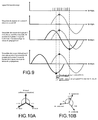
- FIG. 2 shows a sinusoid measured at the end A (solid line) and a sinusoid received from the end B and corrected time tp (dotted).
- tp corrected time
- the current sinusoidal registration is correct for the device located at the end B: the figures 4 , 5A and 5B compared to the figures 2 , 3A and 3B .
- the figure 6 represents a logic diagram illustrating such an operation of the differential protections with this first method of measuring the round trip delay.
- a sinusoidal recalibration error e currents appears in one direction for the device located at the end A.
- This error e is 2 ms, which corresponds to an angular offset of -36 °.
- this error is reflected in the Fresnel diagram by an angular offset between the vector of the current measured locally and the current vector received from the other end and incorrectly recaled.
- This angular phase shift is a function of the difference between the round trip delay and the network frequency.
- a second correction method of the known art which uses a synchronization of the protection devices by a device. external equipment, for example a GPS clock.
- a document referenced [2] at the end of the description describes a protection relay system in a power supply system capable of sampling at the same time several relays which function independently of each other by using a signal coming from a GPS satellite, the sampling times being made identical without having to worry about transmission delay times.
- this second method has a major disadvantage: A loss of the transmission of information between the protection relays installed on the electrical network and the GPS system leads to a total loss of the protection function of this electrical network. In addition, this second method has drawbacks in terms of hardware cost, installation and is likely to reduce the availability and dependability of the protection.
- the first test it is sought, in the case of a two-phase or three-phase network, whether a phase shift of current is found on each of the phases of the network, the compensation being applied only after a delay, which can be of the order of 100 msec.
- the first test it is investigated whether an insulation fault is detected. An alarm is generated when the compensation reaches a first determined level. A second alarm is generated and the protection is blocked when the compensation reaches a second determined level considered unacceptable.
- the invention also relates to a differential protection system for an electrical connection in a medium, high or very high voltage network, comprising two differential protection devices arranged at the two ends of this link, which comprises resynchronization means of these devices. shifted the data received from the end located at a distance of half of the forward / backward propagation time, characterized in that it comprises automatic compensation means by controlling the angle of the current vectors.
- it comprises current phase shift calculation means on each of the network phases, means for taking into account a determined delay, for example of the order of 100 msec.
- it comprises means for detecting an insulation fault, locking means and means for generating an alarm.
- the method of the invention consists in synchronizing the sinusoids of the currents measured locally and the sinusoids of the currents received from the other end of a link by realizing a servocontrol of the current vectors.
- these sinusoids of currents measured locally, and these sinusoids of currents received from a remote measurement are obligatorily synchronized since they are almost identical in amplitude and in phase.
- the method of the invention makes it possible to overcome the disadvantages of a GPS synchronization as used in the second known method of the art, by replacing this GPS synchronization by a synchronization of the current sinusoids without additional cost, available at each end. A and B of the link.
- a time constant of the order of magnitude of 0.5 sec is deliberately introduced into the servo-control function, so as to avoid compensation in the event of a fault appearing on the link.
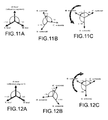
- FIGS 11A and 11B illustrate a misalignment of the current vectors of the Fresnel diagram due to a difference in propagation time at the end A (respectively at the end B) and the figure 11C (respectively 12C) illustrates the realignment of the vectors obtained with the method of the invention.
- the protection system can be blocked (choice of the operator) and an alarm can be generated (choice of the operator) indicating to the operator an anomaly too important in terms of spread.
- the figure 13 represents a logic diagram illustrating the operation of the method of the invention.
- the dashed portions correspond to the operation of the differential protection device of the prior art shown in FIG. figure 6 .
- the values used in the description above correspond to values actually seen on links.
- the propagation times are times typically encountered on communications across a multiplexer.
Landscapes
- Engineering & Computer Science (AREA)
- Power Engineering (AREA)
- Emergency Protection Circuit Devices (AREA)
- Organic Low-Molecular-Weight Compounds And Preparation Thereof (AREA)
Claims (11)
- Verfahren zum Schutz einer elektrischen Verbindung (7) in einem Netz mit mittlerer, hoher oder sehr hoher Spannung, wobei zwei Vorrichtungen zum Differentialschutz bzw. Relais (8, 9) an den beiden Enden (A, B) dieser Verbindung angeordnet sind, umfassend die nachfolgenden Schritte:- Anlegen einer Spannung an das Relais (Schritt 20),- Messen der Hin- und Rückweglaufzeit (Schritt 21),- Nachstellen der Sinuskurven des vom anderen Ende empfangenen Stroms auf Grundlage des Verhältnisses 0,5 Hinweg/0,5 Rückweg (Schritt 22),wobei das Verfahren dadurch gekennzeichnet ist, dass es folgende Schritte umfasst:- einen ersten Test (Schritt 23), um zu erfahren, ob eine bestimmte Zeitspanne abgelaufen ist,1) bei negativer Antwort auf diesen ersten Test (Schritt 23)- Nachstellen der Sinuskurven des vom anderen Ende empfangen Stroms auf Grundlage des Verhältnisses 0,5 Hinweg/0,5 Rückweg (Schritt 24),- Erhalten von Fresnel-Diagrammen des Stroms ohne Regelung der Phasen von dem Ende (Schritt 25),- Berechnen des Differentialstroms und des Haltestroms für jede Phase (Schritt 26),- einen zweiten Test, um zu erfahren, ob einer der Differentialströme in dem Auslösebereich liegt (Schritt 27),- Auslösen des Differentialschutzes bei einer positiven Antwort (Schritt 28) auf diesen zweiten Test.2) Bei positiver Antwort auf diesen ersten Test (Schritt 23) und bei negativer Antwort auf den zweiten Test (Schritt 27),- Test zum Vergleichen der Phasenverschiebung ΔØ zwischen dem lokalen Strom und dem entfernten Strom für jede Phase mit zumindest einem bestimmten Wert und gegebenenfalls Regeln der Phase eines jeden End-stroms auf 180° bezüglich eines jeden entsprechenden lokalen Stroms (Schritt 30).
- Verfahren nach Anspruch 1, wobei bei dem ersten Test im Falle eines Zwei- oder Drei-Phasennetzes untersucht wird, ob eine Phasenverschiebung des Stroms an jeder der Phasen des Netzes festzustellen ist.
- Verfahren nach Anspruch 1, wobei diese bestimmte Zeitspanne in der Größenordnung von 100 ms liegt.
- Verfahren nach Anspruch 1, wobei bei dem ersten Test untersucht wird, ob ein Isolationsfehler festzustellen ist.
- Verfahren nach Anspruch 1, wobei ein Alarm dann erzeugt wird, wenn die Kompensation ein bestimmtes erstes Niveau erreicht.
- Verfahren nach Anspruch 1, wobei ein Alarm dann erzeugt wird und der Schutz dann gesperrt wird, wenn die Kompensation ein bestimmtes zweites Niveau erreicht.
- System zum Schutz einer elektrischen Verbindung (7) in einem Netz mit mittlerer, hoher oder sehr hoher Spannung, enthaltend zwei Vorrichtungen zum Differentialschutz bzw. Relais (8, 9), die an den beiden Enden (A, B) dieser Verbindung angeordnet sind, und umfassend:- Mittel zum Anlegen einer Spannung an das Relais,- Mittel zum Messen der Hin- und Rückweglaufzeit,- Mittel zum Nachstellen der Sinuskurven des vom anderen Ende empfangen Stroms auf Grundlage des Verhältnisses 0,5 Hinweg/0,5 Rückweg, dadurch gekennzeichnet, dass es umfasst:- erste Testmittel, um zu erfahren, ob eine bestimmte Zeitspanne abgelaufen ist,- Mittel zum Erhalten von Fresnel-Diagrammen des Stroms ohne Regelung der Phasen von dem Ende,- Mittel zum Berechnen des Differentialstroms und des Haltestroms für jede Phase,- zweite Testmittel, um zu erfahren, ob einer der Differentialströme in dem Auslösebereich liegt,- Mittel zum Auslösen des Differentialschutzes,- Testmittel zum Vergleichen der Phasenverschiebung ΔØ zwischen dem lokalen Strom und dem entfernten Strom für jede Phase mit zumindest einem bestimmten Wert und zum Regeln der Phase eines jeden Endstroms um 180° bezüglich eines jeden entsprechenden lokalen Stroms.
- System nach Anspruch 7, umfassend Mittel zum Berechnen der Phasenverschiebung des Stroms an jeder der Phasen des Netzes.
- System nach Anspruch 7, umfassend Mittel zum Berücksichtigen einer bestimmten Zeitspanne.
- System nach Anspruch 9, wobei diese bestimmte Zeitspanne in der Größenordnung von 100 ms liegt.
- System nach Anspruch 7, umfassend Mittel zum Erfassen eines Isolationsfehlers, Mittel zum Sperren und Mittel zum Erzeugen eines Alarms.
Applications Claiming Priority (2)
| Application Number | Priority Date | Filing Date | Title |
|---|---|---|---|
| FR0853610A FR2932028B1 (fr) | 2008-06-02 | 2008-06-02 | Procede et systeme de protection differentielle d'une liaison electrique dans un reseau moyenne, haute ou tres haute tension |
| PCT/EP2009/056590 WO2009147078A1 (fr) | 2008-06-02 | 2009-05-29 | Procédé et système de protection différentielle d'une liaison électrique dans un réseau moyenne, haute ou très haute tension |
Publications (2)
| Publication Number | Publication Date |
|---|---|
| EP2283555A1 EP2283555A1 (de) | 2011-02-16 |
| EP2283555B1 true EP2283555B1 (de) | 2015-08-12 |
Family
ID=40086433
Family Applications (1)
| Application Number | Title | Priority Date | Filing Date |
|---|---|---|---|
| EP09757460.2A Active EP2283555B1 (de) | 2008-06-02 | 2009-05-29 | Verfahren und system zum differentialschutz einer elektrischen verbindung in einem netzwerk mit mittlerer spannung, hoher spannung oder sehr hoher spannung |
Country Status (6)
| Country | Link |
|---|---|
| US (1) | US8462476B2 (de) |
| EP (1) | EP2283555B1 (de) |
| CN (1) | CN102047518B (de) |
| CA (1) | CA2730375C (de) |
| FR (1) | FR2932028B1 (de) |
| WO (1) | WO2009147078A1 (de) |
Families Citing this family (5)
| Publication number | Priority date | Publication date | Assignee | Title |
|---|---|---|---|---|
| EP2638611B1 (de) | 2010-11-09 | 2020-10-07 | ABB Power Grids Switzerland AG | Synchronisationsverfahren für stromdifferentialschutz |
| ES2572956T3 (es) * | 2012-07-31 | 2016-06-03 | Abb Research Ltd. | Sincronización de relojes para protección diferencial de línea |
| CN105140894B (zh) * | 2015-08-07 | 2018-09-25 | 许继电气股份有限公司 | 一种基于相位差原理的配电网差动保护方法 |
| EP3136528B1 (de) | 2015-08-31 | 2020-04-22 | Siemens Aktiengesellschaft | Differentialschutzverfahren, differentialschutzeinrichtung und differentialschutzsystem |
| FR3137179B1 (fr) * | 2022-06-28 | 2024-10-04 | Sagemcom Energy & Telecom Sas | Détection de perte de neutre |
Family Cites Families (10)
| Publication number | Priority date | Publication date | Assignee | Title |
|---|---|---|---|---|
| US4851782A (en) * | 1987-01-15 | 1989-07-25 | Jeerings Donald I | High impedance fault analyzer in electric power distribution |
| US5267231A (en) | 1991-07-03 | 1993-11-30 | Abb Power T&D Company Inc. | Digital communication channel interface |
| JPH0837724A (ja) * | 1994-07-22 | 1996-02-06 | Fuji Facom Corp | アナログデータのサンプリング同期制御方法 |
| DE19959793B4 (de) * | 1999-12-07 | 2007-03-08 | Siemens Ag | Differentialschutzverfahren |
| EP1195876B1 (de) | 2000-10-06 | 2007-04-18 | Kabushiki Kaisha Toshiba | Digitales Schutzrelaissystem |
| FR2818454B1 (fr) * | 2000-12-19 | 2003-02-14 | Alstom | Protection pour reseau electrique ayant une liaison radio courte distance dite "bluetooth" |
| MXPA05000537A (es) * | 2002-07-12 | 2005-04-19 | Mc Graw Edison Co | Sistema de proteccion de red electrica. |
| GB2407927B (en) * | 2003-11-07 | 2006-03-01 | Responsiveload Ltd | Responsive electricity grid substation |
| US7480580B2 (en) * | 2005-10-18 | 2009-01-20 | Schweitzer Engineering Laboratories, Inc. | Apparatus and method for estimating synchronized phasors at predetermined times referenced to an absolute time standard in an electrical system |
| JP2008125251A (ja) * | 2006-11-13 | 2008-05-29 | Mitsubishi Electric Corp | 電気所におけるリレー方式およびpcm電流差動リレー方式 |
-
2008
- 2008-06-02 FR FR0853610A patent/FR2932028B1/fr not_active Expired - Fee Related
-
2009
- 2009-05-29 CN CN2009801204963A patent/CN102047518B/zh active Active
- 2009-05-29 EP EP09757460.2A patent/EP2283555B1/de active Active
- 2009-05-29 US US12/994,450 patent/US8462476B2/en active Active
- 2009-05-29 WO PCT/EP2009/056590 patent/WO2009147078A1/fr not_active Ceased
- 2009-05-29 CA CA2730375A patent/CA2730375C/en not_active Expired - Fee Related
Also Published As
| Publication number | Publication date |
|---|---|
| FR2932028B1 (fr) | 2012-12-14 |
| US8462476B2 (en) | 2013-06-11 |
| CN102047518A (zh) | 2011-05-04 |
| FR2932028A1 (fr) | 2009-12-04 |
| WO2009147078A1 (fr) | 2009-12-10 |
| CN102047518B (zh) | 2013-11-06 |
| CA2730375A1 (en) | 2009-12-10 |
| EP2283555A1 (de) | 2011-02-16 |
| US20110069421A1 (en) | 2011-03-24 |
| CA2730375C (en) | 2016-03-01 |
Similar Documents
| Publication | Publication Date | Title |
|---|---|---|
| RU2524383C1 (ru) | Способ синхронизации для дифференциально-токовой защиты | |
| US6678134B2 (en) | Digital protective relay system | |
| EP2520040B1 (de) | Verfahren und vorrichtung zur erkennung von verzögerungsasymmetrien bei kommunikationskanälen | |
| EP3814788B1 (de) | System und verfahren zur fehlerlokalisierung in einem mehrphasigen leistungssystem unter verwendung der entwicklung von vorwärts- und rückwärtsspannung | |
| CA2831115C (en) | Current differential protection | |
| EP2283555B1 (de) | Verfahren und system zum differentialschutz einer elektrischen verbindung in einem netzwerk mit mittlerer spannung, hoher spannung oder sehr hoher spannung | |
| EP2741390B1 (de) | Richtungserkennung einer Störung, insbesondere in einem Netz mit kompensiertem oder isoliertem Nulleiter | |
| FR2649259A1 (fr) | Declencheur statique comportant un systeme de desensibilisation de la protection terre | |
| EP2849195B1 (de) | Zusatzvorrichung für elektrischen Schutzschalter, elektrisches System mit einem Schutzschalter und dieser Zusatzvorrichtung und Verfahren zur Bestimmung des Grunds der Öffnung des Schutzshalters dank dieser Zusatzvorrichtung | |
| US7106565B2 (en) | Directional ground relay system | |
| EP3106887B1 (de) | Verfahren und vorrichtung zur detektion einer störung in einem stromnetz | |
| FR2682190A1 (fr) | Procede de detection selective d'un defaut resistant dans un reseau de distribution d'energie electrique et dispositif pour sa mise en óoeuvre. | |
| FR2976414A1 (fr) | Procede de protection differentielle d'une liaison electrique de grande longueur avec courant capacitif eleve dans un reseau moyenne, haute ou tres haute tension | |
| EP3259815A1 (de) | System für selektiven schutz eines elektrischen netzwerks und zugehöriges schutzverfahren | |
| EP3798648B1 (de) | Verfahren zur bestimmung der position einer fehlervorstufe in einem in betrieb befindlichen hochspannungskabel | |
| FR2969845A1 (fr) | Dispositif et procede de protection terre restreinte | |
| JP4391330B2 (ja) | 事故点標定方法及び事故点標定システム | |
| CA3004694A1 (fr) | Procede et dispositif de mise sous tension d'un transformateur de puissance | |
| EP4468732A2 (de) | Synchronisation von datenerfassungsvorrichtungen eines online-überwachungssystems eines elektrischen verteilungsnetzes | |
| FR2999294A1 (fr) | Detection directionnelle d'un defaut, notamment dans un reseau a neutre compense | |
| Paduraru | End-to-End Testing of the Alpha Plane Characteristic of the New Line Differential Relays Using Satellite Synchronization Signals | |
| Dzienis et al. | Ultra fast relay with small communication requirements | |
| WO2003043159A1 (fr) | Procede de securisation d'un systeme de protection differentielle de jeu de barres dans une ligne a isolation gazeuse, et systeme de protection de secours mettant en oeuvre le procede |
Legal Events
| Date | Code | Title | Description |
|---|---|---|---|
| PUAI | Public reference made under article 153(3) epc to a published international application that has entered the european phase |
Free format text: ORIGINAL CODE: 0009012 |
|
| 17P | Request for examination filed |
Effective date: 20101126 |
|
| AK | Designated contracting states |
Kind code of ref document: A1 Designated state(s): AT BE BG CH CY CZ DE DK EE ES FI FR GB GR HR HU IE IS IT LI LT LU LV MC MK MT NL NO PL PT RO SE SI SK TR |
|
| AX | Request for extension of the european patent |
Extension state: AL BA RS |
|
| DAX | Request for extension of the european patent (deleted) | ||
| RAP1 | Party data changed (applicant data changed or rights of an application transferred) |
Owner name: AREVA T&D PROTECTION & CONTROLE Owner name: ALSTOM GRID PROTECTION & CONTROLE SAS |
|
| RAP1 | Party data changed (applicant data changed or rights of an application transferred) |
Owner name: ALSTOM TECHNOLOGY LTD Owner name: AREVA T&D PROTECTION & CONTROLE |
|
| GRAP | Despatch of communication of intention to grant a patent |
Free format text: ORIGINAL CODE: EPIDOSNIGR1 |
|
| INTG | Intention to grant announced |
Effective date: 20150305 |
|
| RIN1 | Information on inventor provided before grant (corrected) |
Inventor name: MARMONIER, JEAN |
|
| GRAS | Grant fee paid |
Free format text: ORIGINAL CODE: EPIDOSNIGR3 |
|
| GRAA | (expected) grant |
Free format text: ORIGINAL CODE: 0009210 |
|
| AK | Designated contracting states |
Kind code of ref document: B1 Designated state(s): AT BE BG CH CY CZ DE DK EE ES FI FR GB GR HR HU IE IS IT LI LT LU LV MC MK MT NL NO PL PT RO SE SI SK TR |
|
| REG | Reference to a national code |
Ref country code: GB Ref legal event code: FG4D Free format text: NOT ENGLISH |
|
| REG | Reference to a national code |
Ref country code: CH Ref legal event code: EP |
|
| REG | Reference to a national code |
Ref country code: AT Ref legal event code: REF Ref document number: 742892 Country of ref document: AT Kind code of ref document: T Effective date: 20150815 |
|
| REG | Reference to a national code |
Ref country code: IE Ref legal event code: FG4D Free format text: LANGUAGE OF EP DOCUMENT: FRENCH |
|
| REG | Reference to a national code |
Ref country code: DE Ref legal event code: R096 Ref document number: 602009032847 Country of ref document: DE |
|
| REG | Reference to a national code |
Ref country code: LT Ref legal event code: MG4D |
|
| REG | Reference to a national code |
Ref country code: AT Ref legal event code: MK05 Ref document number: 742892 Country of ref document: AT Kind code of ref document: T Effective date: 20150812 |
|
| REG | Reference to a national code |
Ref country code: NL Ref legal event code: MP Effective date: 20150812 |
|
| PG25 | Lapsed in a contracting state [announced via postgrant information from national office to epo] |
Ref country code: LV Free format text: LAPSE BECAUSE OF FAILURE TO SUBMIT A TRANSLATION OF THE DESCRIPTION OR TO PAY THE FEE WITHIN THE PRESCRIBED TIME-LIMIT Effective date: 20150812 Ref country code: FI Free format text: LAPSE BECAUSE OF FAILURE TO SUBMIT A TRANSLATION OF THE DESCRIPTION OR TO PAY THE FEE WITHIN THE PRESCRIBED TIME-LIMIT Effective date: 20150812 Ref country code: GR Free format text: LAPSE BECAUSE OF FAILURE TO SUBMIT A TRANSLATION OF THE DESCRIPTION OR TO PAY THE FEE WITHIN THE PRESCRIBED TIME-LIMIT Effective date: 20151113 Ref country code: NO Free format text: LAPSE BECAUSE OF FAILURE TO SUBMIT A TRANSLATION OF THE DESCRIPTION OR TO PAY THE FEE WITHIN THE PRESCRIBED TIME-LIMIT Effective date: 20151112 Ref country code: LT Free format text: LAPSE BECAUSE OF FAILURE TO SUBMIT A TRANSLATION OF THE DESCRIPTION OR TO PAY THE FEE WITHIN THE PRESCRIBED TIME-LIMIT Effective date: 20150812 |
|
| PG25 | Lapsed in a contracting state [announced via postgrant information from national office to epo] |
Ref country code: SE Free format text: LAPSE BECAUSE OF FAILURE TO SUBMIT A TRANSLATION OF THE DESCRIPTION OR TO PAY THE FEE WITHIN THE PRESCRIBED TIME-LIMIT Effective date: 20150812 Ref country code: IS Free format text: LAPSE BECAUSE OF FAILURE TO SUBMIT A TRANSLATION OF THE DESCRIPTION OR TO PAY THE FEE WITHIN THE PRESCRIBED TIME-LIMIT Effective date: 20151212 Ref country code: ES Free format text: LAPSE BECAUSE OF FAILURE TO SUBMIT A TRANSLATION OF THE DESCRIPTION OR TO PAY THE FEE WITHIN THE PRESCRIBED TIME-LIMIT Effective date: 20150812 Ref country code: PL Free format text: LAPSE BECAUSE OF FAILURE TO SUBMIT A TRANSLATION OF THE DESCRIPTION OR TO PAY THE FEE WITHIN THE PRESCRIBED TIME-LIMIT Effective date: 20150812 Ref country code: HR Free format text: LAPSE BECAUSE OF FAILURE TO SUBMIT A TRANSLATION OF THE DESCRIPTION OR TO PAY THE FEE WITHIN THE PRESCRIBED TIME-LIMIT Effective date: 20150812 Ref country code: PT Free format text: LAPSE BECAUSE OF FAILURE TO SUBMIT A TRANSLATION OF THE DESCRIPTION OR TO PAY THE FEE WITHIN THE PRESCRIBED TIME-LIMIT Effective date: 20151214 Ref country code: AT Free format text: LAPSE BECAUSE OF FAILURE TO SUBMIT A TRANSLATION OF THE DESCRIPTION OR TO PAY THE FEE WITHIN THE PRESCRIBED TIME-LIMIT Effective date: 20150812 |
|
| PG25 | Lapsed in a contracting state [announced via postgrant information from national office to epo] |
Ref country code: NL Free format text: LAPSE BECAUSE OF FAILURE TO SUBMIT A TRANSLATION OF THE DESCRIPTION OR TO PAY THE FEE WITHIN THE PRESCRIBED TIME-LIMIT Effective date: 20150812 |
|
| REG | Reference to a national code |
Ref country code: FR Ref legal event code: PLFP Year of fee payment: 8 |
|
| PG25 | Lapsed in a contracting state [announced via postgrant information from national office to epo] |
Ref country code: CZ Free format text: LAPSE BECAUSE OF FAILURE TO SUBMIT A TRANSLATION OF THE DESCRIPTION OR TO PAY THE FEE WITHIN THE PRESCRIBED TIME-LIMIT Effective date: 20150812 Ref country code: SK Free format text: LAPSE BECAUSE OF FAILURE TO SUBMIT A TRANSLATION OF THE DESCRIPTION OR TO PAY THE FEE WITHIN THE PRESCRIBED TIME-LIMIT Effective date: 20150812 Ref country code: DK Free format text: LAPSE BECAUSE OF FAILURE TO SUBMIT A TRANSLATION OF THE DESCRIPTION OR TO PAY THE FEE WITHIN THE PRESCRIBED TIME-LIMIT Effective date: 20150812 Ref country code: EE Free format text: LAPSE BECAUSE OF FAILURE TO SUBMIT A TRANSLATION OF THE DESCRIPTION OR TO PAY THE FEE WITHIN THE PRESCRIBED TIME-LIMIT Effective date: 20150812 Ref country code: IT Free format text: LAPSE BECAUSE OF FAILURE TO SUBMIT A TRANSLATION OF THE DESCRIPTION OR TO PAY THE FEE WITHIN THE PRESCRIBED TIME-LIMIT Effective date: 20150812 |
|
| REG | Reference to a national code |
Ref country code: DE Ref legal event code: R097 Ref document number: 602009032847 Country of ref document: DE |
|
| PG25 | Lapsed in a contracting state [announced via postgrant information from national office to epo] |
Ref country code: RO Free format text: LAPSE BECAUSE OF FAILURE TO SUBMIT A TRANSLATION OF THE DESCRIPTION OR TO PAY THE FEE WITHIN THE PRESCRIBED TIME-LIMIT Effective date: 20150812 |
|
| PLBE | No opposition filed within time limit |
Free format text: ORIGINAL CODE: 0009261 |
|
| STAA | Information on the status of an ep patent application or granted ep patent |
Free format text: STATUS: NO OPPOSITION FILED WITHIN TIME LIMIT |
|
| 26N | No opposition filed |
Effective date: 20160513 |
|
| PG25 | Lapsed in a contracting state [announced via postgrant information from national office to epo] |
Ref country code: BE Free format text: LAPSE BECAUSE OF NON-PAYMENT OF DUE FEES Effective date: 20160531 Ref country code: SI Free format text: LAPSE BECAUSE OF FAILURE TO SUBMIT A TRANSLATION OF THE DESCRIPTION OR TO PAY THE FEE WITHIN THE PRESCRIBED TIME-LIMIT Effective date: 20150812 |
|
| PG25 | Lapsed in a contracting state [announced via postgrant information from national office to epo] |
Ref country code: LU Free format text: LAPSE BECAUSE OF FAILURE TO SUBMIT A TRANSLATION OF THE DESCRIPTION OR TO PAY THE FEE WITHIN THE PRESCRIBED TIME-LIMIT Effective date: 20160529 |
|
| REG | Reference to a national code |
Ref country code: CH Ref legal event code: PL |
|
| PG25 | Lapsed in a contracting state [announced via postgrant information from national office to epo] |
Ref country code: LI Free format text: LAPSE BECAUSE OF NON-PAYMENT OF DUE FEES Effective date: 20160531 Ref country code: CH Free format text: LAPSE BECAUSE OF NON-PAYMENT OF DUE FEES Effective date: 20160531 |
|
| REG | Reference to a national code |
Ref country code: IE Ref legal event code: MM4A |
|
| REG | Reference to a national code |
Ref country code: FR Ref legal event code: PLFP Year of fee payment: 9 |
|
| PG25 | Lapsed in a contracting state [announced via postgrant information from national office to epo] |
Ref country code: IE Free format text: LAPSE BECAUSE OF NON-PAYMENT OF DUE FEES Effective date: 20160529 |
|
| REG | Reference to a national code |
Ref country code: FR Ref legal event code: PLFP Year of fee payment: 10 |
|
| PG25 | Lapsed in a contracting state [announced via postgrant information from national office to epo] |
Ref country code: CY Free format text: LAPSE BECAUSE OF FAILURE TO SUBMIT A TRANSLATION OF THE DESCRIPTION OR TO PAY THE FEE WITHIN THE PRESCRIBED TIME-LIMIT Effective date: 20150812 Ref country code: HU Free format text: LAPSE BECAUSE OF FAILURE TO SUBMIT A TRANSLATION OF THE DESCRIPTION OR TO PAY THE FEE WITHIN THE PRESCRIBED TIME-LIMIT; INVALID AB INITIO Effective date: 20090529 |
|
| PG25 | Lapsed in a contracting state [announced via postgrant information from national office to epo] |
Ref country code: MK Free format text: LAPSE BECAUSE OF FAILURE TO SUBMIT A TRANSLATION OF THE DESCRIPTION OR TO PAY THE FEE WITHIN THE PRESCRIBED TIME-LIMIT Effective date: 20150812 Ref country code: MT Free format text: LAPSE BECAUSE OF FAILURE TO SUBMIT A TRANSLATION OF THE DESCRIPTION OR TO PAY THE FEE WITHIN THE PRESCRIBED TIME-LIMIT Effective date: 20150812 Ref country code: TR Free format text: LAPSE BECAUSE OF FAILURE TO SUBMIT A TRANSLATION OF THE DESCRIPTION OR TO PAY THE FEE WITHIN THE PRESCRIBED TIME-LIMIT Effective date: 20150812 Ref country code: MC Free format text: LAPSE BECAUSE OF FAILURE TO SUBMIT A TRANSLATION OF THE DESCRIPTION OR TO PAY THE FEE WITHIN THE PRESCRIBED TIME-LIMIT Effective date: 20150812 |
|
| PG25 | Lapsed in a contracting state [announced via postgrant information from national office to epo] |
Ref country code: BG Free format text: LAPSE BECAUSE OF FAILURE TO SUBMIT A TRANSLATION OF THE DESCRIPTION OR TO PAY THE FEE WITHIN THE PRESCRIBED TIME-LIMIT Effective date: 20150812 |
|
| PGFP | Annual fee paid to national office [announced via postgrant information from national office to epo] |
Ref country code: DE Payment date: 20250528 Year of fee payment: 17 |
|
| PGFP | Annual fee paid to national office [announced via postgrant information from national office to epo] |
Ref country code: GB Payment date: 20250526 Year of fee payment: 17 |
|
| PGFP | Annual fee paid to national office [announced via postgrant information from national office to epo] |
Ref country code: FR Payment date: 20250526 Year of fee payment: 17 |