EP4468732A2 - Synchronisation von datenerfassungsvorrichtungen eines online-überwachungssystems eines elektrischen verteilungsnetzes - Google Patents
Synchronisation von datenerfassungsvorrichtungen eines online-überwachungssystems eines elektrischen verteilungsnetzes Download PDFInfo
- Publication number
- EP4468732A2 EP4468732A2 EP24176826.6A EP24176826A EP4468732A2 EP 4468732 A2 EP4468732 A2 EP 4468732A2 EP 24176826 A EP24176826 A EP 24176826A EP 4468732 A2 EP4468732 A2 EP 4468732A2
- Authority
- EP
- European Patent Office
- Prior art keywords
- data acquisition
- time
- signal
- local
- acquisition device
- Prior art date
- Legal status (The legal status is an assumption and is not a legal conclusion. Google has not performed a legal analysis and makes no representation as to the accuracy of the status listed.)
- Pending
Links
Images


Classifications
-
- H—ELECTRICITY
- H04—ELECTRIC COMMUNICATION TECHNIQUE
- H04Q—SELECTING
- H04Q9/00—Arrangements in telecontrol or telemetry systems for selectively calling a substation from a main station, in which substation desired apparatus is selected for applying a control signal thereto or for obtaining measured values therefrom
- H04Q9/04—Arrangements for synchronous operation
-
- G—PHYSICS
- G01—MEASURING; TESTING
- G01R—MEASURING ELECTRIC VARIABLES; MEASURING MAGNETIC VARIABLES
- G01R19/00—Arrangements for measuring currents or voltages or for indicating presence or sign thereof
- G01R19/25—Arrangements for measuring currents or voltages or for indicating presence or sign thereof using digital measurement techniques
- G01R19/2506—Arrangements for conditioning or analysing measured signals, e.g. for indicating peak values ; Details concerning sampling, digitizing or waveform capturing
- G01R19/2509—Details concerning sampling, digitizing or waveform capturing
-
- G—PHYSICS
- G01—MEASURING; TESTING
- G01R—MEASURING ELECTRIC VARIABLES; MEASURING MAGNETIC VARIABLES
- G01R19/00—Arrangements for measuring currents or voltages or for indicating presence or sign thereof
- G01R19/25—Arrangements for measuring currents or voltages or for indicating presence or sign thereof using digital measurement techniques
- G01R19/2513—Arrangements for monitoring electric power systems, e.g. power lines or loads; Logging
-
- G—PHYSICS
- G01—MEASURING; TESTING
- G01R—MEASURING ELECTRIC VARIABLES; MEASURING MAGNETIC VARIABLES
- G01R31/00—Arrangements for testing electric properties; Arrangements for locating electric faults; Arrangements for electrical testing characterised by what is being tested not provided for elsewhere
- G01R31/08—Locating faults in cables, transmission lines, or networks
-
- G—PHYSICS
- G01—MEASURING; TESTING
- G01R—MEASURING ELECTRIC VARIABLES; MEASURING MAGNETIC VARIABLES
- G01R31/00—Arrangements for testing electric properties; Arrangements for locating electric faults; Arrangements for electrical testing characterised by what is being tested not provided for elsewhere
- G01R31/12—Testing dielectric strength or breakdown voltage ; Testing or monitoring effectiveness or level of insulation, e.g. of a cable or of an apparatus, for example using partial discharge measurements; Electrostatic testing
- G01R31/1227—Testing dielectric strength or breakdown voltage ; Testing or monitoring effectiveness or level of insulation, e.g. of a cable or of an apparatus, for example using partial discharge measurements; Electrostatic testing of components, parts or materials
- G01R31/1263—Testing dielectric strength or breakdown voltage ; Testing or monitoring effectiveness or level of insulation, e.g. of a cable or of an apparatus, for example using partial discharge measurements; Electrostatic testing of components, parts or materials of solid or fluid materials, e.g. insulation films, bulk material; of semiconductors or LV electronic components or parts; of cable, line or wire insulation
- G01R31/1272—Testing dielectric strength or breakdown voltage ; Testing or monitoring effectiveness or level of insulation, e.g. of a cable or of an apparatus, for example using partial discharge measurements; Electrostatic testing of components, parts or materials of solid or fluid materials, e.g. insulation films, bulk material; of semiconductors or LV electronic components or parts; of cable, line or wire insulation of cable, line or wire insulation, e.g. using partial discharge measurements
-
- G—PHYSICS
- G01—MEASURING; TESTING
- G01R—MEASURING ELECTRIC VARIABLES; MEASURING MAGNETIC VARIABLES
- G01R31/00—Arrangements for testing electric properties; Arrangements for locating electric faults; Arrangements for electrical testing characterised by what is being tested not provided for elsewhere
- G01R31/12—Testing dielectric strength or breakdown voltage ; Testing or monitoring effectiveness or level of insulation, e.g. of a cable or of an apparatus, for example using partial discharge measurements; Electrostatic testing
Definitions
- the present invention relates to the general field of monitoring the proper functioning of elements present in an electrical distribution network, in particular electrical cables, and more precisely the synchronization between at least two data acquisition devices belonging to an online monitoring system of an electrical distribution network.
- Detection and localization of discharges can provide crucial information to the network operator regarding the condition of the insulation of operating distribution cables and equipment in general.
- TDR time domain reflectometry
- online monitoring systems can detect and localize events that may represent anomalies, such as partial discharge, without affecting the normal operation of the network. Information on the progression of the phenomenon over time can prevent the occurrence of destructive faults, thus improving the reliability indices of the network and preventing the short-circuit current from stressing other equipment. As a result, such online monitoring systems contribute to one of the important aspects of the smart grid, namely the optimal use of existing assets through the implementation of optimized preventive maintenance and intelligent knowledge of the condition of the assets.
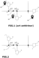
- the principle of online monitoring consists in placing a plurality of online data acquisition devices 1 at predefined locations in the network, for example at the ends of electrical cables present in this network.
- three of these online data acquisition devices 1 have been shown placed at three known locations illustrated by points A, B and C.
- the two devices 1 placed at points A and B can detect events corresponding to a partial discharge occurring at any position of a cable or equipment of the network, for example located between points A and B or even outside these points.
- the two devices 1 placed at points B and C can detect events corresponding to a partial discharge occurring at any position of a cable or equipment of the network, for example located between points B and C, or even outside these points.
- the arrival times t oa HAS and t oa B signals u A (t) and u B (t) acquired by each of the two data acquisition devices 1 must be determined in a common time frame.
- each data acquisition device 1 of the monitoring system with a receiver 10 of a satellite navigation system, for example a GPS receiver 10.
- a receiver 10 of a satellite navigation system for example a GPS receiver 10.
- Each event detected by each of the data acquisition devices 1, for example the previous signal u A (t) or u B (t) generated by a partial discharge can thus be time-stamped in a common reference system.
- This synchronization method is described for example in the document WO 2021/138569 .
- the difference between the arrival times of the signals u A (t) and u B (t) at the two data acquisition devices 1, expressed in a common time reference, and consequently the location Z PD of the partial discharge, can then be determined by applying relations (1) and (2) above.
- Another known method involves injecting high-frequency synchronization pulses into one end of a cable under surveillance of a distribution network, using an inductive coupler.
- This time synchronization method uses the power cable as the transmission medium for the synchronization pulses, which alleviates the disadvantage of satellite invisibility and the atmospheric conditions problems associated with GPS.
- the accuracy of this method is greatly affected by the attenuation and dispersion of the synchronization pulses propagating in the cable. This results in a loss of the time data sent by the cable.
- the present invention aims to overcome the drawbacks of the methods and systems for synchronizing at least two data acquisition devices of an online monitoring system of an electrical distribution network.
- said predefined duration T is greater than at least one estimated time of flight value of a signal between the first and second data acquisition devices.
- said first injected signal and said second injected signal comprise a sequence of high frequency pulses of predefined period.
- said predefined duration T is greater than the sum of the estimated flight time value and said predefined period.
- the method further comprises a timestamp of the high-frequency events detected by the first data acquisition device during a first passive data acquisition phase, via the first local timestamp means, and of the high-frequency events detected by the second data acquisition device during a second passive data acquisition phase, via the second local timestamp means.
- the first passive data acquisition phase is preferably triggered at the second reception time t A2 timestamped by the first local timestamping means.
- the second passive data acquisition phase is preferably triggered at the second injection time t B2 timestamped by the second local timestamping means.
- the first passive data acquisition phase and the second passive data acquisition phase can advantageously be carried out over a time window of the same predetermined duration.
- the first high-frequency event detected by the first data acquisition device and the second high-frequency event detected by the second data device correspond to two signals generated by the same partial discharge at a point of the network located between the first and second data acquisition devices
- ⁇ t oa denotes the difference between the arrival time of the partial discharge at the first data acquisition device time-stamped by the first local time-stamping means and the arrival time of the partial discharge at the second data acquisition device time-stamped by the second local time-stamping means.
- the first local timestamp means and the second local timestamp means are N-bit counters, N being an integer greater than or equal to 16.
- the first local timestamping means is integrated into the first data acquisition device, and/or the second local timestamping means is integrated into the second data acquisition device.
- the synchronization between at least two data acquisition devices of a monitoring system according to the invention will be described in the non-limiting case where the online monitoring system is configured to identify and locate partial discharges in the network.
- the synchronization principle can nevertheless be extended to any online monitoring system having several data acquisition devices which must be synchronized.
- the electrical distribution network is for example a high voltage or medium voltage network, composed of a plurality of electrical cables, connection or hook-up accessories, apparatus and/or transformers.
- the system comprises a plurality of acquisition devices 1 placed at different known points of the network, such as points A, B and C shown in the figure 2 .
- the points A, B, C where the data acquisition devices are located are preferably located at the ends of cables or cable sections.
- the data acquisition devices 1 are preferably placed at easily accessible locations, for example at the transformers.
- each device 1 conventionally comprises, as schematically illustrated in the figure 3 , detection means 11 capable of detecting pulse events caused in the cables by the partial discharges, such as the high-frequency pulses u A (t) and u B (t) generated by the pulse discharge 2 of the figure 2 .
- the means 11 are for example a non-invasive sensor, preferably an inductive sensor 11, located around the cable at the location point of the device.
- the online monitoring system further comprises a local time stamping means 12 associated with each data acquisition device 1, and time synchronization means configured to implement the steps of a synchronization method according to the invention.
- each local time stamping means 12 is either electrically and functionally connected to each device 1, or integrated into each device 1 as illustrated in the figure 3 .
- Each device 1 also comprises injection means 13 configured to generate high-frequency signals and inject these high-frequency signals via the detection means 11. These injection means 13 are part, as will become more clearly apparent below, of the time synchronization means.
- Each data acquisition device 1 may further advantageously comprise a mobile communication module 14 (4G or more) or by Ethernet, allowing it in particular to receive or even control signals emitted by a remote server (not shown) included in the online monitoring system, or to transmit information, such as acquired data, to this server.
- Each local time stamping means 12 is preferably a precise local clock, or a 16-bit or more counter. Such a local time stamping means 12 makes it possible to time stamp each injection of a high-frequency signal, each reception of a high-frequency signal, and each event detected by the high-frequency sensor 11 at the location point of the data acquisition device 1, during a passive data acquisition phase.
- a method of time synchronization, according to the present invention, between the data acquisition devices 1, will now be described with reference to the figures 4 And 5 .
- the explanation is given with respect to the two devices 1 located at points A and B, but can easily be extended to all data acquisition devices 1 present in the online monitoring system of the electrical network.
- the device 1 located at point A is called the "first data acquisition device”
- the device 1 located at point B is called the "second data acquisition device”. Since the two devices are identical, their role can nevertheless be reversed:
- the synchronization method begins with a step 110 during which the first data acquisition device 1 generates a first signal S A (t), and injects this first signal into the network, more precisely into the cable.
- This first signal S A (t), generated or delivered by the injection means 13 of the first device 1, comprises at least one high-frequency pulse. It is thus possible to inject this first signal into the network at point A, using the detection means 11 in an active mode (as opposed to the passive mode in which the detection means 11 receive signals).
- this first signal S A (t) corresponds to a sequence of high-frequency pulses of predetermined period.
- the use of several successive pulses, instead of a single pulse, advantageously improves the resolution of the signals and overcomes the effects of attenuation and dispersion of the signal during its propagation in the cable.
- the injection time t A1 of this first signal is timestamped by the local timestamping means 12 integrated, or more widely associated, with the first device 1, and recorded locally or transmitted for recording to the central server via the communication module 14 of the first device 1.
- the first injected signal propagates through the various components of the network (cables and transformers and/or switching equipment, and/or cable junctions, etc.) until it reaches the second data acquisition device 1.
- This first signal S A (t) is therefore received by the second device 1 during a step 120 via its detection means 11.
- the time of reception t B1 of this first signal is time-stamped by the local time-stamping means 12 integrated into, or more broadly associated with, the second device 1, and recorded locally.
- the second data acquisition device 1 After a predefined duration T following the reception time t B1 , the second data acquisition device 1 generates a second signal S B (t), identical to the first signal, and injects this second signal at point B of the network, more precisely in the cable, using its detection means 11 in an active mode (step 130 on the figures 4 And 5 ).
- the injection time t B2 of this second signal S B (t) is timestamped by the local timestamping means 12 integrated, or more broadly associated, with the second device 1, and recorded locally.
- the predefined duration T separating the reception time t B1 and the injection time t B2 of this second signal S B (t) is preferably chosen to be greater than at least one estimated time-of-flight value of a signal between the first and second data acquisition devices 1.
- the predefined duration T is preferably chosen to be greater than the sum of the estimated time-of-flight value and said predefined period T A/B .
- the estimated time-of-flight value through the network does not need to be precise. It may be an average time-of-flight value through the components of the network.
- This second injected signal S B (t) propagates in the different components of the network (cables and transformers and/or switching devices, and/or cable junctions, etc.) undergoing the same effects as those encountered during the propagation of the first signal S B (t), until reaching the first data acquisition device 1.
- This second signal S B (t) is therefore received by the first device 1 during a step 140 via its detection means 11.
- the time of reception t A2 of this second signal is time-stamped by the means local timestamp 12 integrated, or more broadly associated, with the first device 1, and recorded locally or transmitted for recording to the central server via the communication module 14 of the first device 1.
- This calculation can be performed locally (at the first device 1) or centralized at the remote server.
- Any high-frequency event likely to be detected by the detection means 11 of the first device 1 or of the second device 1 during passive data acquisition phases will subsequently be able to be time-stamped first locally, via the local time-stamping means 12, then in a common reference base thanks to the knowledge of the synchronization difference ⁇ t oa between the two data acquisition devices 1.
- the method therefore comprises the triggering of a first passive phase and a second passive phase of detection of these events at the level of the first data acquisition device 1 and the second data acquisition device 1 respectively, during a time window of the same predetermined duration for the two phases (step 160).
- the first passive data acquisition phase is triggered at the second reception time t A2 and the second passive phase of data acquisition is triggered at the second injection time t B2 .
- Z PD TOF ′ ⁇ ⁇ t oh 2 TOF ′ .
- This calculation step 170 can for example be carried out at the remote central server.
- ⁇ t oa denotes the difference between the arrival time of the partial discharge 2 at the first data acquisition device 1 timestamped by the first local timestamping means 12 and the arrival time of the partial discharge 2 at the second data acquisition device 1 timestamped by the second local timestamping means 12.
- Steps 110 to 150 are preferably repeated periodically (for example once or more times per day) so as to compensate for drifts that may affect the network, such as temperature changes, overloads, and/or dispersion in the meters 12.
Landscapes
- Physics & Mathematics (AREA)
- General Physics & Mathematics (AREA)
- Engineering & Computer Science (AREA)
- Power Engineering (AREA)
- Computer Networks & Wireless Communication (AREA)
- Data Exchanges In Wide-Area Networks (AREA)
- Remote Monitoring And Control Of Power-Distribution Networks (AREA)
- Synchronisation In Digital Transmission Systems (AREA)
- Locating Faults (AREA)
- Maintenance And Management Of Digital Transmission (AREA)
Applications Claiming Priority (1)
| Application Number | Priority Date | Filing Date | Title |
|---|---|---|---|
| FR2305072A FR3149093B1 (fr) | 2023-05-23 | 2023-05-23 | Synchronisation de dispositifs d’acquisition de données d’un système de surveillance en ligne d’un réseau de distribution électrique |
Publications (2)
| Publication Number | Publication Date |
|---|---|
| EP4468732A2 true EP4468732A2 (de) | 2024-11-27 |
| EP4468732A3 EP4468732A3 (de) | 2024-12-04 |
Family
ID=88290831
Family Applications (1)
| Application Number | Title | Priority Date | Filing Date |
|---|---|---|---|
| EP24176826.6A Pending EP4468732A3 (de) | 2023-05-23 | 2024-05-20 | Synchronisation von datenerfassungsvorrichtungen eines online-überwachungssystems eines elektrischen verteilungsnetzes |
Country Status (3)
| Country | Link |
|---|---|
| US (1) | US20250383379A1 (de) |
| EP (1) | EP4468732A3 (de) |
| FR (1) | FR3149093B1 (de) |
Citations (2)
| Publication number | Priority date | Publication date | Assignee | Title |
|---|---|---|---|---|
| WO2004013642A2 (en) | 2002-06-21 | 2004-02-12 | Stichting Voor De Technische Wetenschappen | Method and system for transmitting an information signal over a power cable |
| WO2021138569A1 (en) | 2019-12-31 | 2021-07-08 | 3M Innovative Properties Company | Monitoring system for evaluating a condition of an electrical grid |
Family Cites Families (5)
| Publication number | Priority date | Publication date | Assignee | Title |
|---|---|---|---|---|
| FR3052322B1 (fr) * | 2016-06-02 | 2018-07-06 | Maple High Tech | Methode de synchronisation de nœuds dans un reseau de capteurs sans fil |
| FR3101427B1 (fr) * | 2019-09-26 | 2021-10-08 | Electricite De France | Procédé de détermination d’une position d’un site de décharge partielle dans un câble haute tension en fonctionnement |
| EP4044466B1 (de) * | 2019-10-22 | 2025-02-19 | Huawei Technologies Co., Ltd. | Synchronisationsverfahren und -vorrichtung |
| US11844037B2 (en) * | 2021-07-23 | 2023-12-12 | Charter Communications Operating, Llc | Automated determination of a timing offset for DOCSIS time protocol to provide precision time protocol accuracy |
| CN115963359A (zh) * | 2021-10-13 | 2023-04-14 | 南京南瑞继保电气有限公司 | 一种高压电缆局部放电定位方法、系统及处理装置 |
-
2023
- 2023-05-23 FR FR2305072A patent/FR3149093B1/fr active Active
-
2024
- 2024-05-20 EP EP24176826.6A patent/EP4468732A3/de active Pending
- 2024-05-22 US US18/671,961 patent/US20250383379A1/en active Pending
Patent Citations (2)
| Publication number | Priority date | Publication date | Assignee | Title |
|---|---|---|---|---|
| WO2004013642A2 (en) | 2002-06-21 | 2004-02-12 | Stichting Voor De Technische Wetenschappen | Method and system for transmitting an information signal over a power cable |
| WO2021138569A1 (en) | 2019-12-31 | 2021-07-08 | 3M Innovative Properties Company | Monitoring system for evaluating a condition of an electrical grid |
Also Published As
| Publication number | Publication date |
|---|---|
| FR3149093B1 (fr) | 2025-12-12 |
| EP4468732A3 (de) | 2024-12-04 |
| FR3149093A1 (fr) | 2024-11-29 |
| US20250383379A1 (en) | 2025-12-18 |
Similar Documents
| Publication | Publication Date | Title |
|---|---|---|
| EP2550509B1 (de) | Verfahren und system zur zeitsynchronisation von signalphasen aus entsprechenden messvorrichtungen | |
| EP3798649B1 (de) | Verfahren zur bestimmung der position einer teilentladungsstelle in einem in betrieb befindlichen hochspannungskabel | |
| EP4468733A2 (de) | Synchronisation von datenerfassungsvorrichtungen eines online-überwachungssystems eines elektrischen verteilungsnetzes durch nulldurchgangsdetektion | |
| WO2010069938A1 (fr) | Recepteur numerique large bande comprenant un mecanisme de detection des sauts de phase | |
| EP4468732A2 (de) | Synchronisation von datenerfassungsvorrichtungen eines online-überwachungssystems eines elektrischen verteilungsnetzes | |
| EP4198526B1 (de) | Verfahren und systeme zur bestimmung einer elektrischen grösse in einer elektrischen anlage | |
| EP2693227B1 (de) | System zum Erfassen einer Impedanzänderung eines Nullleiters, Trafostation, die ein solches System umfasst, und Erfassungsverfahren einer Impedanzänderung eines Nullleiters mit einem solchen System | |
| EP2283555B1 (de) | Verfahren und system zum differentialschutz einer elektrischen verbindung in einem netzwerk mit mittlerer spannung, hoher spannung oder sehr hoher spannung | |
| EP2691785B1 (de) | System und verfahren zur erkennung von verschleiss oder unterbrechung eines kabels zur signalübermittlung | |
| EP3943955B1 (de) | Verfahren, vorrichtungen und systeme zur detektion eines isolationsfehlers in einer elektrischen anlage | |
| EP3001208B1 (de) | System zum erkennen einer elektrischen störung, und entsprechendes verfahren | |
| FR3013457A1 (fr) | Systeme de calcul de l'energie electrique, armoire electrique comprenant un tel systeme, poste de transformation et procede de calcul associes | |
| CN109343334A (zh) | 一种利用信号注入法的配电终端对时方法 | |
| FR3030764A1 (fr) | Dispositif et procede de surveillance d'une tension ou d'une intensite, systeme de surveillance d'un tableau electrique, armoire electrique et poste de transformation associes | |
| EP4414721B1 (de) | Verfahren und system zur kalibrierung von spannungsmessungen in einem system zur messung elektrischer grössen | |
| EP3048448B1 (de) | Verfahren und vorrichtung zur überwachung einer spannung oder eines stroms, entsprechendes überwachungssystem einer elektrischen schalttafel, entsprechender schaltschrank und entsprechende transformatoreinheit | |
| EP3798648B1 (de) | Verfahren zur bestimmung der position einer fehlervorstufe in einem in betrieb befindlichen hochspannungskabel | |
| EP3671231A1 (de) | Messverfahren und -system für elektrische grössen | |
| EP2577894A1 (de) | Verfahren zur aktualisierung von temporärer synchronisationsreferenz | |
| FR2983320A1 (fr) | Procede de gestion de la synchronisation d'un systeme distribue d'enregistrement d'evenements horodates | |
| EP4631194A1 (de) | Verfahren zur verzögerungskompensation in einem auf tdma protokoll basierenden datenübertragungsnetz | |
| EP3087789A1 (de) | Kommunikationssynchronisierung in einer fernlesevorrichtung | |
| FR2685779A1 (fr) | Detecteur de defauts pour reseau aerien polyphase de distribution electrique. |
Legal Events
| Date | Code | Title | Description |
|---|---|---|---|
| PUAI | Public reference made under article 153(3) epc to a published international application that has entered the european phase |
Free format text: ORIGINAL CODE: 0009012 |
|
| STAA | Information on the status of an ep patent application or granted ep patent |
Free format text: STATUS: THE APPLICATION HAS BEEN PUBLISHED |
|
| PUAL | Search report despatched |
Free format text: ORIGINAL CODE: 0009013 |
|
| AK | Designated contracting states |
Kind code of ref document: A2 Designated state(s): AL AT BE BG CH CY CZ DE DK EE ES FI FR GB GR HR HU IE IS IT LI LT LU LV MC ME MK MT NL NO PL PT RO RS SE SI SK SM TR |
|
| AK | Designated contracting states |
Kind code of ref document: A3 Designated state(s): AL AT BE BG CH CY CZ DE DK EE ES FI FR GB GR HR HU IE IS IT LI LT LU LV MC ME MK MT NL NO PL PT RO RS SE SI SK SM TR |
|
| RIC1 | Information provided on ipc code assigned before grant |
Ipc: G01R 31/12 20200101ALI20241030BHEP Ipc: G01R 31/08 20200101ALI20241030BHEP Ipc: G01R 19/25 20060101ALI20241030BHEP Ipc: H04Q 9/04 20060101AFI20241030BHEP |
|
| STAA | Information on the status of an ep patent application or granted ep patent |
Free format text: STATUS: REQUEST FOR EXAMINATION WAS MADE |
|
| 17P | Request for examination filed |
Effective date: 20250603 |