EP2283784A1 - Système chirurgical et procédé chirurgical de chirurgie endoscopique transluminale par orifice naturel (notes) - Google Patents
Système chirurgical et procédé chirurgical de chirurgie endoscopique transluminale par orifice naturel (notes) Download PDFInfo
- Publication number
- EP2283784A1 EP2283784A1 EP09738812A EP09738812A EP2283784A1 EP 2283784 A1 EP2283784 A1 EP 2283784A1 EP 09738812 A EP09738812 A EP 09738812A EP 09738812 A EP09738812 A EP 09738812A EP 2283784 A1 EP2283784 A1 EP 2283784A1
- Authority
- EP
- European Patent Office
- Prior art keywords
- assembly
- anvil
- axis
- hollow organ
- linear
- Prior art date
- Legal status (The legal status is an assumption and is not a legal conclusion. Google has not performed a legal analysis and makes no representation as to the accuracy of the status listed.)
- Granted
Links
- 238000000034 method Methods 0.000 title claims abstract description 114
- 238000002674 endoscopic surgery Methods 0.000 title claims description 3
- 210000000056 organ Anatomy 0.000 claims abstract description 326
- 230000002950 deficient Effects 0.000 claims abstract description 197
- 238000003780 insertion Methods 0.000 claims abstract description 168
- 230000037431 insertion Effects 0.000 claims abstract description 168
- 230000003872 anastomosis Effects 0.000 claims abstract description 161
- 230000007246 mechanism Effects 0.000 claims description 233
- 230000001154 acute effect Effects 0.000 claims description 91
- 238000010168 coupling process Methods 0.000 claims description 61
- 238000005859 coupling reaction Methods 0.000 claims description 61
- 230000008878 coupling Effects 0.000 claims description 60
- 239000012636 effector Substances 0.000 claims description 36
- 239000002775 capsule Substances 0.000 claims description 23
- 230000002441 reversible effect Effects 0.000 claims description 15
- 239000012212 insulator Substances 0.000 claims description 11
- 230000000149 penetrating effect Effects 0.000 claims description 5
- 239000004020 conductor Substances 0.000 claims description 2
- 210000001035 gastrointestinal tract Anatomy 0.000 description 201
- 238000010586 diagram Methods 0.000 description 84
- 210000004873 upper jaw Anatomy 0.000 description 39
- 230000009466 transformation Effects 0.000 description 37
- 230000000694 effects Effects 0.000 description 36
- 210000000436 anus Anatomy 0.000 description 23
- 210000001847 jaw Anatomy 0.000 description 19
- 230000005611 electricity Effects 0.000 description 18
- 210000004874 lower jaw Anatomy 0.000 description 17
- 238000001356 surgical procedure Methods 0.000 description 16
- 210000001015 abdomen Anatomy 0.000 description 13
- 230000004308 accommodation Effects 0.000 description 13
- 230000003187 abdominal effect Effects 0.000 description 9
- 238000003384 imaging method Methods 0.000 description 9
- XLYOFNOQVPJJNP-UHFFFAOYSA-N water Substances O XLYOFNOQVPJJNP-UHFFFAOYSA-N 0.000 description 8
- 239000000463 material Substances 0.000 description 7
- 229920001746 electroactive polymer Polymers 0.000 description 6
- 238000000926 separation method Methods 0.000 description 6
- 210000000683 abdominal cavity Anatomy 0.000 description 4
- 238000013459 approach Methods 0.000 description 4
- 230000002093 peripheral effect Effects 0.000 description 4
- 239000008280 blood Substances 0.000 description 3
- 210000004369 blood Anatomy 0.000 description 3
- 238000012790 confirmation Methods 0.000 description 3
- 230000005684 electric field Effects 0.000 description 3
- 238000005516 engineering process Methods 0.000 description 3
- 238000007667 floating Methods 0.000 description 3
- 230000005404 monopole Effects 0.000 description 3
- 238000005096 rolling process Methods 0.000 description 3
- 238000011282 treatment Methods 0.000 description 3
- 230000000712 assembly Effects 0.000 description 2
- 238000000429 assembly Methods 0.000 description 2
- 238000005452 bending Methods 0.000 description 2
- 230000000740 bleeding effect Effects 0.000 description 2
- 230000003247 decreasing effect Effects 0.000 description 2
- 239000011810 insulating material Substances 0.000 description 2
- 230000003902 lesion Effects 0.000 description 2
- 230000007257 malfunction Effects 0.000 description 2
- 238000002271 resection Methods 0.000 description 2
- 239000011347 resin Substances 0.000 description 2
- 229920005989 resin Polymers 0.000 description 2
- 230000004044 response Effects 0.000 description 2
- 238000013519 translation Methods 0.000 description 2
- 229920002595 Dielectric elastomer Polymers 0.000 description 1
- 101000793686 Homo sapiens Azurocidin Proteins 0.000 description 1
- 206010028980 Neoplasm Diseases 0.000 description 1
- 229910000639 Spring steel Inorganic materials 0.000 description 1
- 229910000831 Steel Inorganic materials 0.000 description 1
- RTAQQCXQSZGOHL-UHFFFAOYSA-N Titanium Chemical compound [Ti] RTAQQCXQSZGOHL-UHFFFAOYSA-N 0.000 description 1
- 201000011510 cancer Diseases 0.000 description 1
- 238000007796 conventional method Methods 0.000 description 1
- 238000011161 development Methods 0.000 description 1
- 229920001971 elastomer Polymers 0.000 description 1
- 229910052751 metal Inorganic materials 0.000 description 1
- 239000002184 metal Substances 0.000 description 1
- 210000003205 muscle Anatomy 0.000 description 1
- 230000003287 optical effect Effects 0.000 description 1
- 238000003825 pressing Methods 0.000 description 1
- 230000002035 prolonged effect Effects 0.000 description 1
- 239000004576 sand Substances 0.000 description 1
- 229910001285 shape-memory alloy Inorganic materials 0.000 description 1
- 239000010959 steel Substances 0.000 description 1
- 239000010936 titanium Substances 0.000 description 1
- 229910052719 titanium Inorganic materials 0.000 description 1
- 239000013585 weight reducing agent Substances 0.000 description 1
Images







Classifications
-
- A—HUMAN NECESSITIES
- A61—MEDICAL OR VETERINARY SCIENCE; HYGIENE
- A61B—DIAGNOSIS; SURGERY; IDENTIFICATION
- A61B17/00—Surgical instruments, devices or methods
- A61B17/068—Surgical staplers, e.g. containing multiple staples or clamps
- A61B17/072—Surgical staplers, e.g. containing multiple staples or clamps for applying a row of staples in a single action, e.g. the staples being applied simultaneously
- A61B17/07207—Surgical staplers, e.g. containing multiple staples or clamps for applying a row of staples in a single action, e.g. the staples being applied simultaneously the staples being applied sequentially
-
- A—HUMAN NECESSITIES
- A61—MEDICAL OR VETERINARY SCIENCE; HYGIENE
- A61B—DIAGNOSIS; SURGERY; IDENTIFICATION
- A61B17/00—Surgical instruments, devices or methods
- A61B17/068—Surgical staplers, e.g. containing multiple staples or clamps
- A61B17/072—Surgical staplers, e.g. containing multiple staples or clamps for applying a row of staples in a single action, e.g. the staples being applied simultaneously
-
- A—HUMAN NECESSITIES
- A61—MEDICAL OR VETERINARY SCIENCE; HYGIENE
- A61B—DIAGNOSIS; SURGERY; IDENTIFICATION
- A61B17/00—Surgical instruments, devices or methods
- A61B17/11—Surgical instruments, devices or methods for performing anastomosis; Buttons for anastomosis
- A61B17/115—Staplers for performing anastomosis, e.g. in a single operation
-
- A—HUMAN NECESSITIES
- A61—MEDICAL OR VETERINARY SCIENCE; HYGIENE
- A61B—DIAGNOSIS; SURGERY; IDENTIFICATION
- A61B17/00—Surgical instruments, devices or methods
- A61B17/32—Surgical cutting instruments
- A61B17/3205—Excision instruments
Definitions
- the present invention relates to a surgical system and method by which a diseased or defective site of a hollow organ of a living body (hereinafter “body”) is resected after which the cut-end sections of the hollow organ are stapled, and particularly relates to a system and method for use in Natural Orifice Transluminal 1 Endoscopic Surgery (Hereinafter "NOTES”) which reduces the invasiveness of surgical procedures by eliminating the need for large-scale surgery, such as that involving a conventional abdominal incision.
- NOTES Natural Orifice Transluminal 1 Endoscopic Surgery
- linear stapler linear stapler
- linear stapler linear stapler
- a circular anastomotic surgical stapler is used to staple the two cut-end sections of the remainder of the intestinal tract, and at the same time the cut-end sections of the remainder of the intestinal tract that have been closed by purse-string-like linear-stapling suturing are cut off.
- endoscopic hole a body's natural orifice or separately made endoscopic hole that is made so that endoscopic instruments can be inserted into the body
- An existing circular anastomotic surgical stapler for example as illustrated in Figure 39 (prior art), includes: (1) a head assembly for ligation 1060 that has an anvil component 1000 at the front end; (2) a head component 1061 that is positioned opposite to the anvil component 1000 and that has anastomotic staples and a circular cutter used for circular anastomosis of the two cut-end sections of the hollow organ; (3) a shaft assembly 1050, which is an insertion body to be inserted into the hollow organ, and which has a long, flexible support shaft 1070; (4) an actuator hand assembly 1086 that is connected to the shaft assembly 1050 and that controls the driving of the circular cutter and anastomotic staples; and wherein the anvil component 1000 is constructed so that it is releasably mounted to the head component 1061 via an anvil shaft 1104 and a trocar portion (not shown) that is connected thereto. (See, e.g., Figures 5 -47 of Patent Document 1.)
- an existing linear stapler 1500 includes: (1) an end effector 1503 that has an upper jaw 1504 that opens and closes, and a lower jaw 1505 that is positioned opposite to the upper jaw 1504 and that has one or more linear rows of staples and a linear cutter; (2) an insertion body 1501, to be inserted via an endoscopic hole, that has a long, flexible support shaft 1506 connected to the end effector 1503; and (3) an operating assembly 1502 that is connected to the support shaft 1506 and that controls the driving of one or more linear rows of staples and of the linear cutter.
- an end effector 1503 that has an upper jaw 1504 that opens and closes, and a lower jaw 1505 that is positioned opposite to the upper jaw 1504 and that has one or more linear rows of staples and a linear cutter
- an insertion body 1501 to be inserted via an endoscopic hole, that has a long, flexible support shaft 1506 connected to the end effector 1503
- an operating assembly 1502 that is connected to the support shaft 1506 and that controls the driving of one or more linear
- the shaft assembly 1050 of the circular anastomotic surgical stapler is inserted via, e.g., the anus under the condition that the anvil component 1000 is connected to the head component 1061; when the anvil component 1000 fully passes near the end of the diseased or defective site of the intestinal tract in the direction of the upper end of the intestinal tract (the front end), the anvil component 1000 is pushed and separated from the head component 1061; the shaft assembly 1050 on the side of head component 1061 retracts until the head component 1061 is located near the end of the diseased or defective site of the intestinal tract in the direction towards the anus (the rear end); and by using the linear stapler 1500, which is introduced from the opened abdominal cavity, the respective front and rear ends of the diseased or defective site of the intestinal tract are cut off and removed from the remainder of the intestinal tract, and, at the same time, the cut-end sections are closed by purse-string-like linear-stapling suturing.
- the cutting and linear-stapling suturing of the two end sections of the diseased or defective site are performed linearly in the transverse direction of the intestinal tract by one or more linear rows of staples and a linear cutter (both not shown) that are driven from the rear end to the front end inside the lower jaw 1505.
- the anvil shaft 1104 and the trocar portion (both not shown), which are respectively mounted on either the anvil component 1000 or the head component 1061, and which can be coupled to or decoupled from each other, are inserted by hand via the cut-end sections closed by purse-string-like linear-stapling suturing of the remainder of the intestinal tract, and the cut-end sections are tied tightly to the anvil shaft 1104 and the trocar portion, which are exposed, in a purse-string-like linear-stapling suturing manner (both not shown).
- the ends of the purse-string-like linear-stapling suturing sites toward both the mouth and the anus of the intestinal tract are put together and stapled, and at the same time the purse-string-like linear-stapling suturing sites of the intestinal tract are circularly cut off and removed from the remainder of the intestinal tract.
- the shaft assembly 1050 which is the insertion body of the circular anastomotic surgical stapler, can be inserted into a hollow organ via a natural orifice (e.g., the anus), such procedures as (1) tying the ends of cut-end sections of the remainder of the intestinal tract to the anvil shaft 1104 and the trocar portion in a purse-string-like linear-stapling suturing manner using a ligature after the diseased or defective site of the intestinal tract has been cut off by using the linear cutting/stapling device, and (2) connecting the anvil component 1000 and the head component 1061 via the anvil shaft 1104 and the trocar portion, must be performed by hand from outside the site of incisional opening of the body, and accordingly, large-scale operations are still required.
- a natural orifice e.g., the anus
- the present invention has been made in light of the above problems of the existing technologies, and the objectives of the present invention are to reduce the time and invasiveness of operations by eliminating the need for large-scale surgery, such as that which requires an incision of the abdomen of a body, and to provide a method and system that are that excellent in operability, reliability, and economic efficiency for use in NOTES.
- the invention of Claim 2 is a system for use in NOTES and includes a circular anastomosis surgical stapler that comprises:
- the invention of Claim 3 is a system according to Claim 1 for use in NOTES, and wherein there are accommodated near the connection between the head assembly and the support shaft: (a) a push-tube drive mechanism that moves a push tube forward or backward, with the push tube being provided to allow the anvil assembly to connect with or detach from the head assembly, (b) a staple/cutter driver mechanism that drives the anastomotic staples and the circular cutter (annular blade), and (c) a take-up unit that takes up the thin guide wire; with the operations of the mechanisms and take-up unit being remotely controlled via the operating assembly.
- a push-tube drive mechanism that moves a push tube forward or backward, with the push tube being provided to allow the anvil assembly to connect with or detach from the head assembly
- a staple/cutter driver mechanism that drives the anastomotic staples and the circular cutter (annular blade)
- a take-up unit that takes up the thin guide wire; with the operations of the mechanisms and take-up
- the invention of Claim 4 is a system according to Claim 3 for use in NOTES, and wherein a wireless transmitter/receiver and a battery are further provided near the connection between the head assembly and the support shaft, with the push-tube drive mechanism, the staple/cutter driver mechanism, and the take-up unit being controlled by wireless remote control.
- the invention of Claim 5 is a system according to any of the preceding claims for use in NOTES, and wherein the coupling (engaging) mechanism includes:
- Claim 6 is a system according to any of Claims 1, 2, or 5, for use in NOTES, and wherein are accommodated near the connection portion between the head assembly and the support shaft:
- the invention of Claim 7 is a system according to Claim 6 for use in NOTES, and wherein a wireless transmitter/receiver and a battery are further provided near the connection portion between the head assembly and the support shaft, with the push-tube drive mechanism, the lock-adjustment tube mechanism, and the staple/cutter driver mechanism being controlled by wireless remote control.
- the invention of Claim 8 is a system according to Claim 1 or Claim 2 for use in NOTES, and wherein the thin wire guide is an electric guide wire consisting of an electric conductor, with the front end of the electric guide wire being connected to the acute (rear) end of the trocar via a monopolar electrode; the trocar consists of an insulator or formed separately on the anvil shaft via an insulator and the two purse-string-like linear-stapling suturing sites of the remainder of the hollow organ, on the anvil-assembly side and the head-assembly side, respectively are (1) cauterized successively by conducting a monopolar current to the monopolar electrode via the electric guide wire that has been taken up, and (2) inserted by the trocar via both of said suturing sites so that said suturing sites will be opened.
- the thin wire guide is an electric guide wire consisting of an electric conductor, with the front end of the electric guide wire being connected to the acute (rear) end of the trocar via a monopolar electrode
- the invention of Claim 9 is a system according to Claim 8 for use in NOTES, and wherein the monopolar electrode is buried in the rear end of the trocar, with a small area of the monopolar electrode being exposed at the outer surface of the rear end of the trocar.
- the invention of Claim 10 is a system according to Claim 8 or Claim 9 for use in NOTES, and wherein the monopolar electrode is exposed in a narrow band-like manner of appropriate length in the axial direction at the outer peripheral surface of the rear end of the trocar.
- the invention of Claim 11 is a system according to any of Claims 8 ⁇ 10 for use in NOTES, and wherein the anvil shaft to which the trocar is coupled is also coupled to a rotary means by being rotatably supported by the anvil-shaft support, and is rotated by the rotary means when a monopolar current is conducted to the monopolar electrode.
- the invention of Claim 12 is a system according to any of Claims 8 ⁇ 11 for use in NOTES, and wherein the acute part is releasably connected at the rear end of the anvil assembly and penetrates both purse-string-like linear-stapling suturing sites of the hollow organ on the anvil-assembly side and the head-assembly side that are cauterized successively via the trocar, and detaches (removes) from the anvil shaft so as to be pulled into the head assembly.
- the invention of Claim 13 is a system according to Claim 2 or Claim 12 for use in NOTES, and wherein there is provided an anvil-assembly connecting aid that (a) is inserted so as to be able to be withdrawn from the rear end of the operating assembly to the front end of the head assembly via the inside of the support shaft, (b) consists of a trocar-like acute part, with the front end thereof being formed like a trocar, penetrating via the split-capture portion of the locking part, and (c) has a long, flexible shaft member that is connected to the trocar-like acute part and that aids the anvil assembly in again being coupled to the head assembly.
- the invention of Claim 14 is a system according to any of the preceding claims for use in NOTES, and wherein the anvil assembly has an anvil-assembly-attitude control mechanism that supports the anvil shaft and automatically controls the attitude of the anvil assembly in relation to the anvil shaft so that the main axis of the anvil shaft substantially corresponds to the main axis of the head assembly (X0-axis).
- the invention of Claim 15 is a system according to Claim 14 for use in NOTES, and wherein the anvil-assembly-attitude control mechanism includes: (a) a biaxial oscillating mechanism that can oscillate along the two axes (Y-axis and Z-axis) that meet at right angles with the main axis of the anvil shaft (X-axis), (b) angle sensors, mounted on the connection portion of the anvil shaft, for the Y-axis and Z-axis and (c) a drive means that drive the biaxial oscillating mechanism along Y-axis and Z-axis respectively.
- a biaxial oscillating mechanism that can oscillate along the two axes (Y-axis and Z-axis) that meet at right angles with the main axis of the anvil shaft (X-axis)
- angle sensors mounted on the connection portion of the anvil shaft, for the Y-axis and Z-axis
- a drive means that drive the biaxial oscillating mechanism along Y-axis
- the invention of Claim 16 is a system according to Claim 15 for use in NOTES, and wherein the biaxial oscillating mechanism consists of a gimbal mechanism in which a second frame able to oscillate along the Y-axis is provided on a first frame that is fixed inside the anvil assembly, and an anvil-shaft support able to oscillate along the Z-axis and supporting the anvil shaft is provided on the second frame.
- the biaxial oscillating mechanism consists of a gimbal mechanism in which a second frame able to oscillate along the Y-axis is provided on a first frame that is fixed inside the anvil assembly, and an anvil-shaft support able to oscillate along the Z-axis and supporting the anvil shaft is provided on the second frame.
- the invention of Claim 17 is a system according to either Claim 15 or Claim 16 for use in NOTES, and wherein the drive means consist of servomotors that control the drive of the biaxial oscillating mechanism along the Y-axis and the Z-axis respectively.
- the invention of Claim 18 is a system according to Claim 17 for use in NOTES, and further including an anvil-assembly-attitude control mechanism that comprises:
- the invention of Claim 19 is a system according to Claim 17 for use in NOTES, and further including an anvil-assembly-attitude control mechanism that comprises:
- the invention of Claim 20 is a system according to any of the preceding claims for use in NOTES, and wherein there is provided an wireless endoscope device or capsule endoscope device, with the front-end assembly of the endoscope arranged in the vicinity of the front end of the head assembly.
- the invention of Claim 21 is a system according to any of the preceding claims for use in NOTES, and wherein there is further provided (1) an anvil-assembly connecting aid that consists of a long, flexible, hollow shaft whose two ends are open and via which the rear end of the anvil shaft and the trocar can be inserted, and (2) a holding part that is provided at the rear end of the hollow shaft and that is inserted into the hollow organ under the condition that the rear end of the anvil shaft and the trocar are inserted into the front end of the hollow shaft so that the anvil assembly is coupled to the anvil-assembly connecting aid.
- an anvil-assembly connecting aid that consists of a long, flexible, hollow shaft whose two ends are open and via which the rear end of the anvil shaft and the trocar can be inserted
- a holding part that is provided at the rear end of the hollow shaft and that is inserted into the hollow organ under the condition that the rear end of the anvil shaft and the trocar are inserted into the front end
- the invention of Claim 22 is a system for use in NOTES, and including a linear stapler that comprises:
- the invention of Claim 23 is a system according to Claim 22 for use in NOTES, and wherein the pair of linear cutters of the end effector move back and forth in the direction opposite to each other due to the linear-staple/cutter-driving mechanism provided inside the other jaw.
- the invention of Claim 24 is a system according to Claim 23 for use in NOTES, and wherein the linear-staple/cutter-driving mechanism includes a linear staple/cutter driver shaft that (1) is rotatably provided inside a channel dug facing the rear of the staple cartridge in which one or more linear rows of suture staples are accommodated, (2) is removably fit inside the jaw (unmovable jaw) facing the one jaw (opening/closing jaw), and (3) has a male screw on which reverse screws in the right and left directions are formed on either the anterior half and or the posterior half of the male screw; and front-end and rear-end staple-driving mechanisms, both of which (1) have a wedge mechanism that is threadedly engaged with the respective left and right reverse screws of the linear-staple/cutter-driving mechanism, and (2) move back and forth in the direction opposite to each other inside the channel accompanying the reversible rotation of the linear staple/cutter driver shaft, so as to drive the one or more linear rows of suture staples; and wherein
- the invention of Claim 25 is a method for use in NOTES, and includes a circular anastomosis surgical stapler that comprises an anvil assembly that has an anvil shaft on which a trocar is protrudes rearward along the main axis (X-axis) at the rear end of the anvil assembly so that the anvil assembly is used as the front end of the circular anastomosis surgical stapler; an insertion body that is positioned opposite to the anvil assembly and that includes a head assembly that has (1) a circular cutter (annular blade) for cutting off in the cylindrical direction a specified section of a hollow (tubular) organ, (2) one or more annular rows of anastomotic staples for use in circular anastomosis of the two cut-end sections of the remainder of the hollow organ, and (3) a long, flexible support shaft that is connected to the head assembly; an operating assembly that is connected to the insertion body and that controls the driving of the circular cutter (annular blade) and the anastomotic staples; a thin guide
- the invention of Claim 26 is a method for use in NOTES, using a circular anastomosis surgical stapler that comprises:
- the invention of Claim 27 is a method for use in NOTES, using a circular anastomosis surgical stapler that comprises:
- the invention of Claim 28 is a method according to any of Claims 25 ⁇ 27 for use in NOTES, with said method using an anvil-assembly-attitude control mechanism that is inside the anvil assembly and connected to the anvil shaft, and that automatically controls the attitude of the anvil assembly in relation to the anvil shaft so that the main axis of the anvil shaft substantially corresponds to the main axis of the head assembly (X0-axis) when the anvil assembly is again coupled to the head assembly after the anvil assembly is removed from the head assembly.
- an anvil-assembly-attitude control mechanism that is inside the anvil assembly and connected to the anvil shaft, and that automatically controls the attitude of the anvil assembly in relation to the anvil shaft so that the main axis of the anvil shaft substantially corresponds to the main axis of the head assembly (X0-axis) when the anvil assembly is again coupled to the head assembly after the anvil assembly is removed from the head assembly.
- the invention of Claim 29 is a method according to Claim 28 for use in NOTES, using an anvil-assembly attitude-control system that includes:
- the invention of Claim 30 is a method according to Claim 28, for use in NOTES, using an anvil-assembly attitude-control system that includes
- the invention of Claim 31 is a method for use in NOTES, using a linear cutting/stapling device that includes
- Claims 1, 2, 25, and Claim 26 of the present invention disclose the following: an insertion body of a circular anastomosis surgical staplers is inserted via a natural orifice of the body into a hollow organ that has a diseased or defective site, and the anvil assembly is detached from the head assembly and temporarily remains near the front-end section of the diseased or defective site of the hollow organ, and the head-assembly-side insertion body retracts to near the rear end of the diseased or defective site, so as to create a space between the anvil assembly and the insertion body. Under this condition, a linear-stapling/cutting device is inserted into the body via an endoscopic hole to near the diseased or defective site of the hollow organ.
- all of the drive units such as a push-tube drive mechanism to couple and decouple the anvil assembly to the head assembly, a staple/cutter driving mechanism, and a take-up unit for taking up the thin wire guide, are accommodated in a connection portion between the head assembly and the support shaft, and the operation of all the drive units is performed by remote-control via the operating assembly.
- a wireless receiver and battery are provided near the connection portion between the head assembly and the support shaft, and control of the push-tube driving mechanism, the staple/cutter driving mechanism, and the take-up unit is effected remotely and wirelessly.
- the back-and-forth movement of the lock-adjusting pipe opens and closes the split-capture part located at the front end of the push tube together with the forward moving of the split-capture part, then captures the locked part of the anvil shaft and rolls back the push tube, so that the anvil assembly is pulled toward the head-assembly side, and at the same time the anvil assembly can be easily locked to the head assembly.
- the reliability of the coupling mechanism between the anvil assembly and the head assembly is improved.
- the push-tube drive mechanism, the lock-adjustment-tube drive mechanism, and the stable/cutter drive are accommodated near the connection portion between the head assembly and the support shaft, and control of those mechanisms is remotely performed via the operating assembly.
- those drive units' connecting members traditionally provided in the operating assembly such as the push tube, lock-adjustment tube, and driver tube to drive the staple/cutter, and hence the structures of the operating assembly and support shaft are simplified considerably, and it is possible to provide a system and method that further improve the operability and economic efficiency of the surgical devices for use in NOTES.
- a wireless receiver and a battery are further equipped near the connection portion between the head assembly and the support shaft, and the control of the push-tube drive mechanism, the lock-adjustment-tube drive mechanism, the staple/cutter driving mechanism, and the take-up unit is performed remotely and wirelessly.
- the control of the push-tube drive mechanism, the lock-adjustment-tube drive mechanism, the staple/cutter driving mechanism, and the take-up unit is performed remotely and wirelessly.
- the purse-string-like linear-stapling suturing sites of the two portions of the remainder of the hollow organ on the anvil-assembly side and the head-assembly side, respectively are cauterized successively by galvanization by monopolar electricity to the monopolar electrode via the rolled-up electric guide wire, so that the anvil shaft can easily penetrate purse-string-like linear-stapling suturing sites, and the contacting, reconnection, and locking of the anvil assembly to the head assembly becomes easy, and there is no need to connect the anvil assembly to the head assembly by a human hand from outside the site of the incision opening of the abdomen, as used to be done in previous procedures.
- the monopolar electrode exposes only a small area and is buried on the outer circumference at the rear end of the trocar, so that, by galvanization of monopolar electricity to the monopolar electrode, there is the effect of increasing the efficiency of cauterization of the purse-string-like linear-stapling suturing sites of the two portions of the remainder of the hollow organ.
- the monopolar electrode is exposed to an appropriate length in the axial direction on the outer circumference at the rear end of the trocar, so that cauterization of the purse-string-like linear-stapling suturing sites of the two portions of the remainder of the hollow organ is done by sequential movements in the axial direction via monopolar electrical galvanization to the monopolar electrode, which has the effect of further increasing the efficiency of cauterization.
- the anvil shaft that is connected to the trocar rotates when the monopolar electrode is galvanized by monopolar electricity, so as to prevent the burning out of the purse-string-like linear-stapling suturing sites of the two portions of the remainder of the hollow organ that could result from galvanization of monopolar electricity, which has the effect of further increasing the efficiency of cauterization.
- the acute part of the anvil shaft is able to easily penetrate both of the purse-sting-like linear-stapling suturing sites of the two portions of the remainder of the hollow organ on the anvil-assembly side and the head-assembly side, which sites are cauterized successively and pulled to the head-assembly side.
- the diseased or defective site of the hollow organ is cut off and removed from the remainder of the hollow organ and the two cut-end sections of the remainder of the hollow organ are closed by purse-string-like linear-stapling suturing.
- the anvil assembly is equipped with an anvil-assembly-attitude control mechanism that automatically controls the gradient attitude relating to the anvil shaft so that the central (main) axis of the anvil shaft substantially corresponds to the central (main) axis of the head assembly, which makes it is easy to reconnect the anvil assembly to the head assembly after being separated therefrom.
- anvil-assembly-attitude control mechanism that automatically controls the gradient attitude relating to the anvil shaft so that the central (main) axis of the anvil shaft substantially corresponds to the central (main) axis of the head assembly, which makes it is easy to reconnect the anvil assembly to the head assembly after being separated therefrom.
- the anvil-assembly-attitude control mechanism includes (1) a biaxial oscillating mechanism that can oscillate along the two axes (Y-axis and Z-axis) that intersect orthogonally with the anvil main axis (X-axis), (2) angle sensors for the Y-axis and Z-axis, and (3) a drive means for driving the biaxial oscillating mechanism along the Y-axis and Z-axis, which has the effect of automatically and stably controlling the gradient attitude relating to the anvil shaft so that the central (main) axis of the anvil shaft substantially corresponds to the central (main) axis of the head assembly.
- the biaxial oscillating mechanism consists of a gimbal mechanism in which a second frame body that is able to oscillate along the Y-axis is installed in the first frame body, which is fixed inside the anvil assembly, and an anvil-shaft support that is able to oscillate along the Z-axis and to support the anvil shaft is installed in the second frame body, which has the effect of saving space and providing high reliability and stableness of anvil-shaft-attitude control procedures.
- the drive means are two servomotors that control the drive of the biaxial oscillating mechanism along the Y-axis and Z-axis, respectively, which has the effect of controlling the anvil-shaft attitude with high accuracy and high speed.
- the anvil assembly in addition to having effects similar to those of Claims 11-14, Claim 18, or Claim 28, in the anvil-attitude control system, the anvil assembly is pulled by the thin wire guide and is moved to inside the locking portion of the head assembly, or is moved closer to the push-tube front end in which the locking portion is formed.
- the anvil-attitude control system automatically controls the attitude of the anvil with reference to the target angle of the anvil shaft, which is roughly set to fit the angle data of the head assembly at that time, which has the effect of ensuring the reliability of the anvil-attitude control system.
- the push tube and the head assembly are together pushed out forward to meet the acute-part connection hole that is formed rearward of the anvil shaft.
- the anvil-attitude control system automatically controls the attitude of the anvil assembly with reference to the target angle of the anvil shaft, which is set to roughly fit the angle data of the head assembly at that time, which has the effect of ensuring the reliability of the anvil-attitude control system.
- the anvil assembly that is connected at the front end of the anvil-assembly insertion aid is inserted via the natural orifice of the body and into a hollow organ that has a diseased or defective site, and then separated from the anvil-assembly insertion aid and allowed to temporarily remain as it is, so that the anvil assembly and the anvil-assembly insertion aid are temporarily left at the front end and rear end, respectively, of the diseased or defective site of the hollow organ.
- the linear cutting/stapling device is inserted into the body via an endoscopic hole that is opened so that endoscopic instruments can be inserted into the body, where it cuts off and removes the diseased or defective site from the remainder of the hollow organ.
- the anvil-assembly insertion aid is removed from the natural orifice, after which the anvil assembly is reconnected to the head assembly of the circular anastomosis surgical stapler, which, while within the hollow organ, performs circular anastomosis of the two cut-end sections of the remainder of the hollow organ, and at the same time cuts off the purse-string-like linear-stapling suturing site of the remainder of the hollow organ, which has the effect of enabling the sections to be easily again interconnected.
- the linear cutting/stapling device that is inserted into the body via an endoscopic hole, quickly cuts off the respective front-end and rear-end sections of the diseased or defective site of the hollow organ by using a pair of linear cutters that move back and forth to and from each other in reverse directions so as to pinch the diseased or defective site from both sides toward the middle portion of the diseased or defective site straight in the transverse direction, and at the same time the linear cutting/stapling device quickly closes the respective cut-end sections of the remainder of the hollow organ by using the suture staples that are driven so as to pinch, straight in transverse direction, the diseased or defective site, from the two sides toward the middle portion of the diseased or defective site, thereby eliminating the current need for a large-scale abdominal incision and reducing the operating time and invasiveness of the surgical procedure, which has the effect of providing a system and method that are improved in operability of the surgical devices and the reliability and economic efficiency of the operation for use in NOTES.
- a pair of linear cutters move back and forth to and from each other in reverse directions, or move so as to pinch the diseased or defective site from the two sides toward the midsection of the diseased or defective site and then quickly cut off the diseased or defective site of the hollow organs straight in the transverse direction, as a result of which the cutting time is reduced to one-half that of the time of an existing device that is equipped with one cutter and that moves only in one direction. Also, it is possible to efficiently cut off the diseased or defective site from the hollow organ in such a way that the thin wire guide of the circular anastomosis surgical staplers temporarily remains in said midsection, thereby keeping stable the cutting function.
- the linear-staple/cutter-driving mechanism has (1) a front-end staple-driving mechanism and a rear-end staple-driving mechanism that are respectively screwed to the male and reverse screws formed on the anterior half and posterior half of the linear staple/cutter driver shaft installed in the other jaw, and that move reciprocally back and forth, and (2) a pair of linear cutters that are vertically installed on the front end and rear-end staple-driving mechanisms, respectively, so that it is possible to make the linear-staple/cutter-driving mechanism simple and compact.
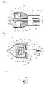
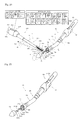
- Fig. 1 is a conceptual diagram of the system and method for use in NOTES showing the main configuration concept in one implementation form (Embodiment 1) for carrying out the this invention.
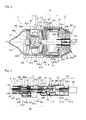
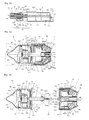
- Fig. 2 is a perspective diagram of the circular anastomosis surgical stapler 1 for the system for use in NOTES, showing the main configuration concept.
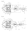
- Fig. 3 is a vertical-section diagram of the head assembly shown in Fig. 2 .
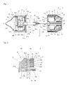
- Fig. 4(a) is a vertical-section diagram of the anvil assembly shown in Fig. 2
- Fig. 4(b) is a cross-sectional diagram taken along the section lines P-P shown in 4(a).
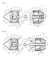
- Fig. 5 is a vertical-section diagram of the anvil assembly and the head assembly shown in Fig. 2 and coupled with each other.
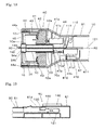
- Fig. 6 is a vertical-section diagram showing the main configuration concept of the operating assembly shown in Fig. 2 .
- Fig. 7 is a vertical-section diagram of the anvil assembly and the head assembly shown in Fig. 2 , decoupled from each other.
- Fig. 8 is an enlarged sectional diagram of the E-portion shown in Fig. 6 .
- all of the attached drawings are conceptual diagrams showing the main configuration concept expressed at NTS scale, and, especially in Figs. 3-5 , the radial direction is enlarged compared to the axial direction in order to easily show the inside configuration.
- the system of Embodiment 1 for use in NOTES is as shown in Fig. 1 , and comprises: (1) a circular anastomosis surgical stapler 1 that (a) is inserted via a natural orifice Ma of a body M to inside a hollow organ T that has a diseased or defective site; and (b) performs circular anastomosis of the two cut-end sections of the remainder of the hollow organ from inside the hollow organ T after the diseased or defective site has been cut off and removed from the remainder of the hollow organ, which at the same time has been closed by purse-string-like linear-stapling suturing of the two cut-end sections of the remainder of the hollow organ; (2) a linear cutting/stapling device 500 that is inserted via an endoscopic hole Mb or Md that is opened on the body M so that endoscopic instruments can be inserted into the body via a cannula Mc, and that cuts off and removes the diseased or defective site T3 from the remainder of the hollow organ T and at the same time closes the cut-
- the circular anastomosis surgical stapler 1 of Embodiment 1 is as shown in Fig. 1, 2 , and includes: (a) an anvil assembly 3 that configures the forward portion of the device and that has an anvil shaft 34 on its rear end along the main axis (X-shaft); (b) a head assembly 4 that sits opposite to the anvil assembly 3 and includes a circular cutter 45 (see Fig.
- an operating assembly 6 that is connected to the rear end of the insertion body 2 and that controls the locking/unlocking of the coupling mechanism, the driving of the anastomotic staples 10 and the circular cutter 45, and other operations.
- the head assembly 4 comprises: (a) a tapered head outer casing 41, whose rear-end diameter is reduced to equal the outer diameter of the support shaft 5; (b) a staple cartridge 44 that is housed in the front end of the head outer casing 41, and that includes one or more annular rows of staple accommodation slots 44a that accommodate a number of anastomotic staples 10 (see Fig.
- a tubular circular cutter 45 that has the same central axis as the above-mentioned parts 41, 44, 44 in the staple cartridge 44;
- a tubular staple-driving finger 43 that is housed at the rear end of the head outer casing 41, and that drives the anastomotic staples 10 outside the front-end surface of said staple cartridge;
- a staple/cutter driver 42 that fixes the respective rear ends of the tubular-shaped staple-driving finger 43 and the circular cutter 45 and simultaneously drives the anastomotic staples 10 and the circular cutter 45 together forward along the main axis (X0).
- a push tube 7 and connecting pipe 53 are inserted (see Fig. 6 ) from the operating assembly 6 via the supporting shaft 5 and arranged to have the same central (principal) axis as the head assembly 4, and the front ends of the push tube and the connecting pipe 7a, 53a are leaded to the inside of the head assembly 4.
- the rear end of the connection pipe 53 is fixed to the inside of the operation assembly 6. Details regarding the push tube 7 are presented below.
- the staple/cutter driver 42 is connected to the front end of a drive tube 52 and is loosely mounted on the outer surface of the connecting pipe 53 so as to be movable back and forth via the drive tube 52 by the operating assembly 6, as described later. Due to the driving by the staple/cutter driver 42, a number of anastomotic staplers 10 and the circular cutter 45 are driven forward at the same time.
- the above-described members of the head assembly 4 can be the same as those described in Patent Document 1, for example.
- a locking portion 54 is provided at the front end 7a of the push tube 7, and it detachably captures the locked portion 35 on the anvil shaft 34 that protrudes at the rear end of the anvil assembly 3, as will be described below (see Figs. 3 and 5 ).
- the configuration and function of the locking portion 54 and the push tube 7 also are described later.
- the push tube 7 is loosely inserted in the connection pipe 53 so as to be movable back and forth via the locking portion 54 of the front end so as to impact the front end of the anvil shaft 34 of the anvil assembly 3, which is pulled toward the head assembly 4 by the operating assembly 6 and into the interior of said push tube 7, and on the other hand, to push out the anvil shaft 34 and to separate the anvil shaft 34 from the locking portion 54 (see Figs. 5 and 6 ).
- a wireless-endoscope insertion-tube body 121 and wireless-endoscope front end 122 are inserted from the operating assembly to near the front end 7a of the push tube 7, passing via the support shaft 5.
- An electric guide wire 100 which is a thin wire guide, also is inserted (see Figs. 3-5 ).
- the configuration inside the push tube 7 and the configuration of the anvil assembly 3 are among of the main distinctive features of the present invention, in which a unique technology is included. These configurations and functions are precisely explained later.
- the anvil assembly 3 comprises: (1) a tubular anvil 31; (2) a hollow, conical end cap 36 that has a small, convex-curved face and that is coupled detachably at the front end of the tubular anvil 31; (3) a tubular lining washer 37 of that is housed in the groove portion 31a and that receives a blade edge of the circular cutter 45; (4) an anvil shaft 34 that protrudes at the rear end of the anvil 31 along the main axis (X axis), with said anvil shaft 34 connected by its rear end to a trocar 34b; (5) an anvil-assembly-attitude control mechanism 30 that automatically controls the anvil-assembly's inclined attitude against the anvil shaft 34, which is rotatably supported on the anvil-shaft support 33c that is installed in the middle of the anvil 31 and fixed to a bracket 32 that is mounted in a protruding condition inside the anvil 31; (6) a flexible cover 38 that seals the
- a number of staple-forming grooves 31b are formed at the rear-end face of the anvil 31 on the respective circumferences of the two concentric circles that correspond to the staple accommodation slot 44a that is at the front-end face of the staple cartridge 44 inside the head assembly 4.
- a number of staple-forming grooves 31b respectively receive a number of anastomotic staples 10 driven from the staple accommodation slot 44a and bend the respective tips of the anastomotic staples 10, being pressed by the tubular staple-driving finger 43, so as to perform circular anastomosis of the two cut end sections of the remainder of the hollow organ.
- a trocar 34b that has a monopolar electrode 34c on its rear end is connected at the rear end of the anvil shaft 34 via the insulator 34a.
- the anvil shaft 34, the insulator 34a, and the trocar 34b are all connected at almost equal radii, and the rear end of the trocar 34b, which has the monopolar electrode 34c, is formed as a sharp leading shape so as to easily penetrate the purse-string-like linear-stapling suturing sites T1a, T2a on the two portions T1, T2 of the remainder of the hollow organ (see Fig. 7 ), as described below.
- the reasons for using the insulator 34a and the monopolar electrode 34c are presented below.
- the monopolar electrode 34c of appropriate length is exposed and buried in a narrow band-like manner in the axial direction on the outer peripheral surface at the rear end of the trocar 34b.
- the exposed width and length of the monopolar electrode 34c are set so as to correspond to the characteristic features, such as the thickness of the tube walls, of the purse-string-like linear-stapling suturing sites T1a, T2a on the two portions T1, T2 of the remainder of the hollow organ ( Fig. 7 ).
- the cauterization of the respective purse-string-like linear-stapling suturing sites T1a, T2a is done sequentially in the axial direction by galvanization of monopolar electricity to the monopolar electrode 34c, which has the effect of increasing the efficiency of the cauterization.
- the anvil shaft 34 which is coupled with the trocar 34b, is connected to a rotating means, as described later, being supported rotatably on an anvil support shaft 33c, and is rotated by the rotating means when the monopolar electrode 34c is galvanized by monopolar electricity.
- the anvil shaft 34 which is connected to the trocar 34b, rotates when the monopolar electrode 34c is galvanized by the monopolar electricity, so as to prevent the branding of the respective purse-sting-like suturing sites T1a, T2a on the two portions of the remainder of the hollow organ T (see Fig. 7 ) that would otherwise result due to the galvanization of the monopolar electrode 34c by monopolar electricity, which has the effect of further increasing the efficiency of the cauterization.
- a convex-shaped locked portion 35 is formed on the outer surface of the anvil shaft 34 near the forward part of the insulator 34a and is coupled with and fixed to the locking portion 54 that is provided at the front end of the push tube 7 in the head assembly 4.
- the coupling mechanism which is composed of the locking portion 54 and the locked portion 35, is necessarily provided with: (1) a function that keeps those portions connected so that the anvil assembly 3 faces the head assembly 4 but is apart from the head assembly 4 by the specified gap E; and (2) a positioning function that controls and mechanically specifies the angles around the respective main axes (X-axis, X0-axis) of the anvil assembly 3 and head assembly 4, so that the staple accommodation slots 44a are positioned opposite to their corresponding staple-forming grooves 31b.
- the coupling mechanism can be made having the same configuration as those of existing embodiments, such as those described in Patent Document 1.
- the coupling mechanism provides a spline mechanism so that the locking portion 54 and the locked portion 35 freely move slidably in the axial direction to and from each other, though their rotation around the main axes (X-axis, X0-axis) is restrained.
- concave spline grooves (female splines) 54a are formed on the inner surface of the locking portion 54
- convex spline grooves (male splines) 35a are formed on the outer surface of the locked portion 35, in such a way that the concave an convex grooves are able to engage each other. Therefore, the above-mentioned two angles around the respective main axes (X-axis, X0-axis) of the anvil assembly 3 and the head assembly 4 are controlled and mechanically specified so that the staple accommodation slots 44a are positioned opposite to the staple-forming grooves 31b.
- the two ends of the respective outer surfaces of the locked portion 35 and the locking portion 54 are chamfered and become smooth, inclined faces, so that the cauterized opening of the respective purse-string-like linear-stapling suturing sites T1a, T2a on the two portions T1, T2 of the remainder of the hollow organ are easily penetrated, and the locked portion 35 is easily mated and engaged with the locking portion 54.
- the locking portion 54 can be made of electroactive polymer (EAP) material, which constricts due to galvanization. In this case, the locking portion constricts due to galvanization and tightly holds the locked portion 35, and stopping the galvanization releases the holding of the locked portion 35.
- EAP electroactive polymer
- a dielectric elastomer If a dielectric elastomer is placed in a strong electric field, it constricts in the electric field and expands in the direction perpendicular to the electric field. This deforming force is referred to as a Maxwell stress. If a condenser-like member that is made of EAP dielectric bodies so that it has elasticity similar to rubber is set between two charged electrode plates that are then galvanized, a positive charge is stored in one electrode and a negative charge is stored in the other electrode. Attracting forces arise, and the condenser-like member is pressed by these forces, and then the EAP dielectric bodies' quality of expanding toward the surface is used to cause the locking portion to lock. Such EAP materials are manufactured and sold, for example, in the U.S.A by Artificial Muscle Inc. and by Santa Fe Science and Technology, and in Japan by Emex Co., Ltd.
- the monopolar electrode 34c is installed on the rear end of the trocar 34b, which is connected to the rear end of the anvil shaft 34.
- the electric guide wire 100 (a thin wire guide) is inserted from the operating assembly 6 to the head assembly 4, passing via the inside of the push tube 7, and the electric guide wire 100 is then connected to the monopolar electrode 34c.
- the electric guide wire 100 has the following three functions when circular anastomosis of the two cut ends of the diseased or defective site T3 of the remainder of the hollow organ T is performed: (1) a retracting function that retracts the anvil assembly 3, which is separated from the head assembly 4 by rolling up the electric guide wire 100, to the head assembly 4; (2) a continuation function of continuing the retracting operation (rolling up of the electric guide wire 100) and maintaining the coupling/locking of anvil assembly 3 and head assembly 4, and a supplementary function of unlocking and separating the anvil assembly 3 from the head assembly 4 by releasing the electric guide wire 100; and (3) a cauterized-site-opening function, by which the monopolar electrode is galvanized by monopolar electricity so that the anvil shaft 34 penetrates the respective purse-string-like linear-stapling suturing sites T1a, T2a on the two portions T1, T2 of the remainder of the hollow organ, and is pulled to the head-assembly side 4, where the respective purse-string-like linear-stapling su
- the lock/unlock mechanism of the anvil assembly 3 and the head assembly 4 that employs the EAP materials can be replaced by the take-up/release of the electric guide wire 100 at the time of coupling/locking of the anvil assembly 3 and head assembly 4.
- the anvil-assembly-attitude control mechanism 30 includes: (1) a biaxial oscillating mechanism 33 that can oscillate along the two axes (Y-axis, Z-axis) that orthogonally intersect the anvil main axis (X-axis); (2) angle sensors 305, 306 that are installed around the Y-axis and Z-axis at the anvil-shaft support 33c; and (3) a driving means that drives the biaxial oscillating mechanism 33 around the y-axis and Z-axis.
- the biaxial oscillating mechanism 33 is a gimbal mechanism in which a second frame body 33b is installed in the first frame body 33f, which is fixed at the bracket 32 inside the anvil 31, and which oscillates around the Y-axis.
- An anvil-shaft support 33c is installed in the second frame body and supports the anvil shaft, which oscillates around the Z-axis.
- the anvil shaft 34 is inserted in the anvil-shaft support 33c and supported rotatably, and the front end of said the anvil shaft 34 is connected to the rotating shaft of the anvil-shaft-rotation motor 307, which is one of the driving means.
- a noninterference hole 33e is opened on the X axis, which is the center axis of the first frame body 33f, so that the first body frame 33f does not interfere with the anvil-shaft-rotation motor 307.
- Said driving means are composed of a Y axis servomotor 300 that controls the driving of the second frame body 33b around the Y axis, and a Z axis servomotor 301 that controls the driving of the anvil-shaft support 33c around the Z axis, which have the effect of controlling the anvil shaft 34 attitude with high accuracy and high speed.
- a battery 302 is provided in the anvil assembly 3 as the source of electricity for the Y, Z axis servomotors 300, 301, for the Y, Z axis-angle sensors 305, 306, and for the wireless transceiver (transmitter/receiver) 303 that communicates the control signals between those devices and the operating assembly 6.
- the support shaft 5 of the circular anastomosis surgical stapler 1 comprises: (1) an outer tube 51 whose front end is connected to the head outer casing 41 of the head assembly 4, and whose rear end is connected to an operating-assembly housing 61; (2) a driver tube 52; (3) a connecting pipe 53; and (4) a push tube 7 — all of which are inserted concentrically inside the outer tube 51.
- the wireless-endoscope insertion-tube body 121 and electric guide wire 100 are passed inside and via the push tube 7.
- the members that constitute the support shaft 5 or other members inside the support shaft 5 are all made of flexible materials. As a result, members used for existing medical-purpose devices, such as a circular anastomosis surgical stapler or an endoscope, can be used.
- the operating assembly 6 of the circular anastomosis surgical stapler 1 includes: (1) an operating-assembly housing 61 that has an approximately tubular shape and that is connected with the outer tube 51 of the support shaft 5 at the front end of the operating-assembly housing 61; (2) a push-tube drive mechanism 64 that moves the push tube back and forth; and (3) a staple/cutter driving mechanism 66 that drives the anastomotic staples 10 and the circular cutter 45.
- the push-tube drive mechanism 64 and the staple/cutter driving mechanism 66 are both electric-motor-driven and differ from the manual adjusting-knob mechanism and the staple/cutter driving-handle mechanism such as the prior art described in Patent Document 1.
- the push-tube drive mechanism 64 comprises: (1) a mail-screw shaft 72 that is connected to the rear end of the push tube 7, which is passed inside and via the support shaft 5 and moves slidably back and forth via the U-shaped clip 76; and (2) a push-tube drive motor 90 mounted at the rear end of the operating-assembly housing 61.
- a hollow rotation nut 62 is supported rotatably at the front end of the push-tube drive mechanism 64 by a bracket 61b that is mounted in a protruding condition on the inner surface of the operating-assembly housing 61, and wherein a female-screw portion 62b that is formed at the front end of the rotation nut 62 is screwed with the male-screw shaft 72 that is housed in the rotation nut 62, and the rotation shaft 90a of the push-tube drive motor 90 is fixed into the motor connection hole 62a that is located on the rear-end face of the rotation nut 62.
- the push tube 7 moves back and forth by the driving force of the male-screw shaft 72 which is screwed with the rotation nut 62. At this time, the rotation around the center axis of the push tube 7 is restrained by the U-shaped clip 76 by which the rotation break screw 78 is inserted on the side face of the U-shaped clip 76.
- the male-screw shaft 72 which is connected to the push tube 7, retracts to a recessed position in its normal initial condition, as shown in Fig. 6 .
- An indicator indicates on the scale (not shown) of an indication window 61d the driving strokes of the staple/cutter driver 42 in response to the back-and-forth movement of the push tube 7.
- the other elements of a safety mechanism to prevent malfunction of the staple/cutter driving mechanism 66, the above-specified indicators, and so on, can be configured to be the same as those of many embodiments of existing circular anastomosis surgical staplers, and so illustrations and a detailed explanation are omitted here.
- Said safety mechanism engages with the indicator so that the indicator inclines backward along the scale marks (not shown) and indicates the specified driving stroke of staple/cutter driver 42 when the anvil assembly 3 is coupled and locked with the head assembly 4 while maintaining a specified gap E (see Fig. 8 ).
- the size of the specified gap E between the anvil assembly 3 and the head assembly 4 at the time of the locking of both the assemblies almost equals the sum of the thicknesses on the anvil-assembly side T1 and head-assembly side T2 of the remainder of the hollow organ.
- the staple/cutter driving mechanism 66 comprises: (1) a male-screw tube 52a that is connected to the rear end of the driver tube 52, which moves forward and pushes out the staple/cutter driver 42, on the circumference of which are formed male screws 52b and the male-screw tube 52a is passed via the inside of the driver tube 52 by the connecting pipe 53; (2) an externally-toothed rotating nut 65 that is rotatably supported by the coupling of a hollow rear-half area 65c with the connecting pipe 53, wherein external teeth 65a are formed on the forward half of the outer circumference and female screws 65b are formed on the forward half of the inner surface being screwed to the male tube 52a; (3) a staple/cutter driving motor 91 that is fixed at the lower opening portion of the front end of the operating-assembly housing 61; and (4) a staple/cutter driver shaft 63 whose rear end is connected to the rotation shaft of the staple/cutter driving motor 91 and on whose front end a pinion 63a
- the male-screw tube 52a that is connected with the driver tube 52 is usually back at a recessed position, as shown in Fig. 6 . Due to the rotation/reverse rotation of the externally-toothed rotating nut 65 that is driven by the staple/cutter driving motor 91, the driver tube 52 moves back and forth by the driving force of the male-screw tube 52a, which is screwed to the externally-toothed rotating nut 65. At this time, the rotation of the externally-toothed rotating nut 65 around the central axis of the push tube 7 is restrained by a key/guide groove mechanism (not shown) that is installed between the connection pipe 53 and the push tube 7.
- the operating assembly 6 includes: (1) a take-up unit 110 that takes up or releases the electric guide wire 100 by a motor (not shown), and that is withdrawn from a roller-guide aperture 7g that is opened at the lower-rear portion of the push tube 7, wherein the electric guide wire 100 is connected to the monopolar electrode 34c on the rear end of the trocar 34b, which is inserted into the push tube 7 from the head assembly 4 and passed via the inside of the push tube 7, reaching the rear end of the push tube 7; (2) an insertion-tube body 121 that is withdrawn in a bent U-shape from the roller-guide aperture 7b that is opened at the upper-rear portion of the push tube 7; and (3) a wireless endoscope 120 that is equipped with a wireless endoscope unit 130 that is connected to the rear end of the insertion-tube body 121.
- a safety/electronic-control configuration can be employed.
- a safety/electronic-control configuration includes, e.g., a take-up detecting sensor (not shown in the figure) for the take-up unit, wherein the lengths of the back-and-forth movements of the electric guide wire 100 that is connected to the anvil assembly 3 are measured by the take-up detecting sensor, and therefore the specified gap E between the anvil assembly 3 and the head assembly 4 and the specified strokes of the anastomotic staples 10 are displayed on a monitor (not shown in the figure), and the safety/electronic-control configuration can be applied by introducing a motor-drive interlock such as a staple/cutter driving motor 91.
- a motor-drive interlock such as a staple/cutter driving motor 91.
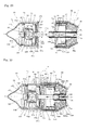
- Fig. 9 shows the main configuration concept of the wireless endoscope 120.
- Fig. 9(a) is a side-elevation view of the endoscope 122
- Fig. 9(b) is a front-elevation view of the front end of the endoscope 122.
- the wireless endoscope 120 in Embodiment 1 comprises a flexible insertion-tube body 121 whose rear end is connected with the front end of the endoscope 122 and whose front end is connected with the wireless endoscope unit 130 of the insertion-tube body 121. It is possible to employ a configuration similar to those described in Patent Application Publication (translation of PCT application) 2004-524076 . A detailed explanation is omitted here.
- the front end of the endoscope 122 is composed of: (1) an optical window 124 that is installed on the insertion-tube body 121 and formed to be a convex curved surface, such as an ellipsoid, that is suitable for optimizing the conditions of image graphics; (2) a CMOS imaging machine 125 that is arranged in the center of the front end of the endoscope 122; a number (number 4 in Fig.
- LEDs light-emitting diodes
- CMOS imaging machine 125 (3) a utility channel 121a that is equipped with a utility channel 127 that is installed in the lower-near portion of the endoscope 122 and used, for example, to supply air and cleansing water to the inside of the abdomen, or to suction blood and water from the inside of the abdomen.
- a wireless endoscope unit 130 (2) a wireless transceiver (transmitter/receiver) 131 that communicates control signals and images, (3) a CMOS imaging machine 125, and (4) a battery 132 that serves as the source of electric power for the wireless transceiver 131.
- Embodiment 1 it is possible to use the battery 132 as an electric-power source, by employing the light-emitting diodes (LEDs) 126 of a low-power-consuming element and the CMOS imaging machine 125.
- the CMOS is advantageous, when compared with a CCD, in its low-power consumption and in point of the system being on a chip.
- wireless endoscope unit 130 are: (1) utility-control devices for supplying sources of air/cleansing water and for suctioning blood/water, (2) a control knob to move the front end of the endoscope 122, and (3) a wireless transceiver to communicate control signals to the operating assembly 6.
- the image signals from the CMOS imaging machine 125 are transmitted via the wireless transceiver 131 using microwaves or wireless periodicity applying some kind(s) of digital- or analog-modulation technique(s).
- an FSK (frequency shift keying)-modulation technique can be used to transmit digital images via a wireless channel.
- Some configuration elements, such as image sensors and irradiation sources, are single-use battery-operate units.
- the wireless endoscope 120 is superior in operability to a conventional wireless endoscope.
- An operating unit 140 is provided at an upper position of the operating-assembly housing 61, as shown in Fig. 1 , and it includes at least the following: an endoscope monitor; an anvil-shaft-angle monitor; a push-tube-driving-motor operation LED (push-tube-drive-motor operation-indicating lamp); a staple/cutter driving-motor operation LED (a staple/cutter-drive-motor c); an endoscope ON/OFF switch (hereinafter "SW") (a switch for operating the wireless endoscope); an electric-guide-wire release/take-up SW (take-up unit 110: electric-guide-wire 100 release/take-up SW); a monopole ON/OFF SW (monopolar current ON/OFF switch); an anvil-shaft rotation/stop SW; an X-axis-servomotor operation LED (X-axis servomotor operation-indicating lamp); a Y-axis-servomotor operation LED (Y-axis-servomotor Y-axis-servomotor operation-indicating
- Wireless operation using the operating unit 140 operates the circular anastomosis surgical stapler 1, as is explained below.
- Fig. 10 is a block diagram showing the main configuration concept of Embodiment 1 of the anvil-assembly attitude-control system for the system for use in NOTES.
- the anvil-assembly attitude-control system of Embodiment 1 comprises: (a) two axes (Y0-axis, Z0-axis)-angle sensors 401, 402 that are installed in the head assembly 4 and that orthogonally intersect the main axis (X0-axis) of the head assembly 4; (b) a head-assembly-side transceiver 403 that wirelessly transmits output from the above-mentioned angle sensors 401, 402; (c) an anvil-assembly-side transceiver 303 that is installed inside the anvil assembly 4 and that receives the output of the Y0-axis-and Z0-axis-angle sensors 401, 402 from the head-assembly-side transceiver 403; and (d) an angle-command generator 310 that includes (1) an angle detector 311 that detects all angle data, using the output of the Y-axis and Z-axis-angle sensors 305, 306 from the anvil-assembly-
- the anvil assembly 3 that is separated from the head assembly 4 floats in an unstable position, inclining toward the head assembly 4 in the remainder of the hollow organ of the body M (see Fig. 1 ) and is suspended and inclining toward the head assembly 4.
- the electric guide wire 100 tries to pull the anvil assembly 3 and to connect the anvil assembly 3 to the head assembly 4, and at this time also applying the anvil-attitude control system.
- the rear end of the trocar 34b in the anvil assembly 3 is pulled by the electric guide wire 100 and is moved to inside of the locking portion 54 that is an anvil-shaft-coupling portion, or is moved closer to near the front end 7a of the push tube 7, in which the locking portion 35 is formed.
- the anvil-assembly-attitude control system automatically controls the attitude of the anvil assembly 3, referring to the target angle of the anvil shaft 34, which is roughly specified to fit the angle data of the head assembly 4, which are angles of the Y0-axis, Z0-axis-angle sensors 401, 402 at that point in time.
- the main axis (X-axis) of the anvil shaft 34 conforms to the main axis X0-axis of the head assembly 4, and then, as shown in Fig. 5 , the anvil shaft 34 easily couples into the push tube 7 and a coupling/lock state can be achieved.
- the circular anastomosis surgical stapler 1 of the present invention comprises: (1) an anvil-assembly-attitude control mechanism 30 that wirelessly controls the attitude of the anvil assembly 3 in relation to the anvil shaft 34; (2) a monopolar electrode 34c at the rear end of the trocar 34b; (3) an electric guide wire 100 that is connected to the monopolar electrode 34c and the take-up unit 110 of the electric guide wire 100; (4) a push-tube drive motor 90 that moves the push tube 7 back and forth, and presses the anvil assembly 3 forward and separates the anvil assembly 3 from the head assembly 4; (5) a staple/cutter driving mechanism 66 that causes the anastomotic staples 10 and the circular cutter 45 to move forward and backward; and (6) a wireless endoscope 120 that is inserted into and passes via the push tube 7 to the front end of the push tube 7.
- the entire system is controlled by a wireless electronic-control system that most differentiates the present invention's configuration from those of the existing circular anastomosis surgical staple
- Fig. 11 is a perspective diagram of the linear stapler 500 for the system for use in NOTES, showing the main configuration concept in one mode (Embodiment 1) for carrying out the present invention
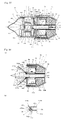
- Fig. 12 is a vertical-section diagram showing the end effector 503 of Fig. 11 when the upper jaw is open.
- Fig. 13 is a vertical-section diagram showing the end effector 503 of Fig. 11 the upper jaw is closed.
- Fig. 14 is a cross-sectional diagram taken along section lines A-A shown in Fig. 13 .
- Fig. 15 is a cross-sectional diagram taken along section lines B-B shown in Fig. 13 .
- Fig. 16 is a cross-sectional diagram taken along section lines C-C shown in Fig. 13 .
- the linear stapler 500 in Embodiment 1 of the present invention is comprised of, from its front end: (1) an insertion body 501, that is to be inserted into a body's abdominal cavity via an endoscopic hole, and that includes an end effector 503 that has (a) an upper jaw 504 that can open and close; (b) a lower jaw 505 that faces the upper jaw 504 and is equipped with two linear rows of suture staples 511 that linearly staple a specified section of a hollow organ, and a pair of (front-end/rear-end) linear cutters 558, 559 (see Figs.
- the linear stapler 500 of the present invention differs from those of conventional linear cutting/stapling devices (linear staplers) — e.g., the conventional linear stapler described in Patent Document 2 — especially in regard to the pair of (front-end/rear-end) linear cutters 558, 559 and the linear staple/cutter driver (driving) mechanism 520 that drives these linear cutters (see Fig. 12 ), as described later. Except for these two main differences, the configuration of the members in the present device can be same as those of various kinds of conventional linear cutting/stapling devices (linear staplers).
- the lower jaw 505 comprises: a lower-jaw body 550 whose rear end 550b can either be down as a flat rectangular shape of the plan view (see Fig. 16 ) or can stand upright to form an L shape; a staple cartridge 510 that is detachably housed in the upper surface of the lower jaw 550, facing the upper jaw 504, and that accommodates two linear rows of suture staples 511 in the longitudinal direction; a linear staple/cutter driver (driving) mechanism 520 that is installed in the channel 551 facing the lower plane of the staple cartridge 510 and that drives the pair of (front-end/rear-end) linear cutters 558, 559 to move back and forth opposite to each other.
- a linear staple/cutter driver (driving) mechanism 520 that is installed in the channel 551 facing the lower plane of the staple cartridge 510 and that drives the pair of (front-end/rear-end) linear cutters 558, 559 to move back and forth opposite to each other.
- a dovetail-groove-type slide groove is formed in front of the rear end 550b and engages with and supports the rear end of the upper jaw 504 and causes the upper jaw 504 to slide up and down.
- An upper-jaw opening/closing drive shaft 554 is inserted rotatably in the upper-shaft support hole 552 that is provided in the back-and-forth direction.
- a number of staple accommodation slots 512 that accommodate a number of the suture staples 511 are provided in two linear rows in the staple cartridge 510, and said staple accommodation slots 512 pierce the staple cartridge 510 in the upper and lower directions (see Fig. 11 ).
- the linear staple/cutter driver (driving) mechanism 520 16 comprises: (1) a linear staple/cutter driver (driving) shaft 555 that is rotatably installed in the lower-shaft support hole 553 that is longitudinally formed in the channel 551 in the lower portion of the lower jaw 505, and that includes a male screw on which reverse screws in the right and left directions 555a, 555b are formed on the anterior and posterior halves of the male screw; and (2) a front-end staple-pushing (driving) member (hereinafter "front-end staple-driver") 556 and a rear-end staple-driver 557 that are provided, respectively, with a slope 556a, 557a, with both of said staple-drivers having a wedge mechanism to push out (drive), in order, the two linear rows of suture staples 511.
- front-end staple-driver front-end staple-driver
- rear-end staple-driver 557 that are provided, respectively, with a slope 556a, 557a, with both of
- the front-end staple-driving mechanism 556 and the rear-end staple-driving member (hereinafter rear-end staple-driver) 557 are threadedly engaged with the left and right reverse male screws 555a, 555b, and move back and forth in directions opposite to each other inside the channel 551, accompanying the reversible rotation of the linear staple/cutter driver shaft 555, so as to drive the suture staples 511.
- a pair of linear cutters are arranged along either the left or right side of the staple cartridge 510 so as to pass via the staple cartridge 510, and are put in a standing position on the front-end staple-driver 556 and rear-end staple-driver 557 so that the two blade edges face each other and move toward the upper jaw 504.
- Respective concave notches 558a, 559a are formed on the upper blade edge of the (front-end/rear-end) linear cutters 558, 559, respectively.
- the concave notches 558a, 559a have a noninterference function so that only the hollow organ T will be incised, without cutting the thin wire guide (electric guide wire) 100 of the circular anastomosis surgical stapler 1 (see Fig. 1 ).
- the upper blade edges of the pair of (front-end/rear-end) linear cutters 558, 559 overlap each other when they meet at the middle portion 555c of the linear staple/cutter driver shaft 555.
- the cutting of a specific portion of the hollow organ ( Fig. 1 ) is carried out effectively.
- the concave notches 558a and 559a are also formed to have a noninterference function so that only the hollow organ T is incised, without cutting the thin wire guide (electric guide wire) 100 of the circular anastomosis surgical stapler 1.
- the rear ends of the upper-jaw opening/closing drive shaft 554 and the linear staple/cutter driver (driving) shaft 555 are connected, respectively, to flexible drive shafts 560, 562, via couplings 561 and 563, and are driven by a motor of the operating assembly 602, as described below.
- the upper jaw 504 in this Embodiment 1 can have the same configuration as that of one of the various kinds of existing linear cutting/stapling devices (linear staplers), and comprises: a rectangular upper-jaw body 540 corresponding to the lower jaw 505; a staple guide 544 in the lower portion of the upper-jaw body 540, opposite to the staple cartridge 510 of the lower jaw 505; and an upper-jaw opening/closing mechanism 530 that has the rectangular shape of the plan view and that is installed at the groove portion 541 and that opens and closes the upper jaw 504 in the upper and lower directions.
- linear staplers linear cutting/stapling devices
- a dovetail-groove-type slide groove 542 is formed at the rear end of the upper jaw 504, and the dovetail-groove-type slide groove 542 is slidably engaged/supported with the dovetail-groove-type slide groove 550a that is located in the upright portion of the rear-end 550b of the lower-jaw body 550.
- the upper-jaw opening/closing mechanism 530 differs from that of existing linear staplers, as shown, for example, in Figs. 12-15 , and is comprised of: a rack 543 on one of the two sides of the groove portion 541 of the upper-jaw body 540; an upper-jaw opening/closing drive shaft 554 that has a pinion 554a on its front end and that mates with the rack 543; and a dovetail-groove-type slide groove 542 that is engaged/supported slidably with the dovetail-groove-type slide groove 550a of the lower-jaw body 550, and that enables the upper-jaw body 540 to slide up and down through the rack 543.
- the upper-jaw opening/closing drive shaft 554 rotates normally/reversely, which causes the upper-jaw body 540 to slide up and down via the rack 543, and said sliding makes the upper jaw 504 open and close with the lower jaw 505.
- Fig. 17 is a block diagram showing the main procedures of the method of Embodiment 1 of the present invention for use in NOTES.
- Embodiment 1 of the present invention for use in NOTES as applied to, for example, a body M, with the intestinal tract being the hollow organ T of that body, includes the following main steps.
- Step 1S making endoscopic hole(s)).
- Step 2S laparoscopic identification of diseased or defective site of intestinal tract.
- the endoscope 600 is used to carefully observe the diseased or defective site and the location thereof from inside the intestinal tract T and via the (wireless) operating units 140 and 509, respectively, and via various kinds of monitors and the operation-indicating LED of the circular anastomosis surgical stapler 1 and the linear stapler 500. In this way, the NOTES is performed carefully.
- the insertion body 2 of the circular anastomosis surgical staplers 1 of which the anvil assembly 3 is connected to the head assembly 4 is inserted via a natural orifice (e.g., the anus Ma) of the human body M until the front end of the anvil assembly 3 fully passes via the diseased or defective site T3 in the intestinal tract T (Step 11S: insertion of circular anastomosis surgical stapler into intestinal tract).
- the anvil assembly 3 is inserted until the monopolar electrode 34c ( Fig. 4 ) at the rear end of the trocar 34b passes near the front-end section C 1 of the diseased or defective site T3 of the intestinal tract T and reaches the intestinal tract on the anvil-assembly side (in the direction of the mouth) T1.
- the electric guide wire 100 is released using the release operation of the take-up unit 110 of the circular anastomosis surgical stapler 1.
- the anvil assembly 3 is forced to move forward by the push-tube drive motor 90, and the anvil assembly 3 is pushed out via the coupling mechanism of the anvil shaft 34, after which the anvil assembly 3 is separated from the head assembly 4, with the anvil assembly 3 temporarily left inside the intestinal tract on the anvil-assembly side T1.
- Step 12S release of anvil assembly from head assembly.
- the head assembly 4 is unlocked from and released from the anvil shaft 34 (the locking portion 54 separates from the locked portion 35), and the push tube 7 is moved back to its recessed position (see Figs. 5 and 6 ).
- Said anvil-assembly separation is observed and confirmed from outside the intestinal tract T by the endoscope 600, and at the same time is observed and confirmed from inside the intestinal tract T by the wireless endoscope 120 that has been inserted in the head assembly 4 of the circular anastomosis surgical staplers 1.
- the insertion body 501 having the closed-jaw end effector 503 of the linear stapler 500 is inserted near said diseased or defective site T3 of the intestinal tract T, through the cannula Mc via the endoscopic hole Mb or Md (Step 21S: insertion of linear stapler into intestinal tract).
- Step 12S When the anvil assembly is being released from the head assembly (Step 12S), it is also possible to withdraw the insertion body 2 on the head assembly 4 side and to move it back to position C2 of the intestinal tract T2, holding the anvil assembly 3 that has been inserted into the intestinal tract T1 on the anvil assembly 3 side (in the direction of the mouth) together with the hollow organ T1 from outside the hollow organ T1.
- the anvil assembly 3 By thus keeping the anvil assembly 3 near the front-end section C1 of the diseased or defective site T3 of the intestinal tract, it is possible to separate the head assembly 4 and to set it precisely near the rear-end section C2 of the diseased or defective site T3.
- the jaw-opening/closing motor 507 of the operating assembly 602 of the linear stapler 500 is continuously operated to open the upper jaw 504 of the end effector 503, and to hold any of the near front-end/rear-end sections C1 C2 of the diseased or defective site T3 so that the upper jaw 504 of the end effector 503 is closed (Step of holding one end section of the diseased or defective site of the intestinal tract 22S).
- the linear-staple/cutter driving motor 508 of the operating assembly 602 is operated, and the front-end linear-staple driver 556 and the front-end linear cutter 558, and the rear-end linear-staple-driver 557 and the rear-end linear cutter 55, respectively move in directions opposite from the front end and rear end of the end effector 503 to the center portion of the opening of the end effector 503, and approach each other.
- the front-end linear-staple driver 556 and the front-end linear cutter 558, and the rear-end linear-staple-driver 557 and the rear-end linear cutter 55 respectively move in directions opposite from the front end and rear end of the end effector 503 to the center portion of the opening of the end effector 503, and approach each other.
- a number of the suture staples 511 are driven, in order, from both the front end and rear end of the end effector 503 and one of the two of the front-end/rear-end sections C1, C2 of the diseased or defective site T3 of the intestinal tract is closed by purse-string-like linear-stapling suturing straight in the transverse direction (purse-string-like linear-stapling suturing site T1a or T2a) so as to wrap the electric guide wire 100 of said circular anastomosis surgical stapler 1.
- the (front-end/rear-end) linear cutters 558, 559 see Figs.
- Step 23S cutting off one end section of diseased or defective site of intestinal tract and closing that cut-end section of the remainder of intestinal tract by purse-string-like linear-stapling suturing).
- Step 24S cutting off other end section of diseased or defective site of intestinal tract and closing the corresponding cut-end section of the remainder of the intestinal tract by purse-string-like linear-stapling suturing).
- each of the suture staples 511 is formed by being pressed, by the front-end/rear-end linear staple-driver 556, between the staple-forming grooves 544a, which are the lower face of the staple guide 544 of the upper jaw 504, and by the front-end/rear-end linear staple-driver 556, 557, in order to close the front-end/rear-end sections C1/C2 of the intestinal tract on the anvil-assembly side (in the direction of the mouth) T1 and on the head-assembly side (in the direction of the anus) T2 by purse-string-like linear-stapling suturing straight in the transverse direction.
- Each blade edge of the pair of said (front-end/rear-end) linear cutters 558, 559 cuts off straight in the transverse direction the respective front-end/rear-end sections C1, C2 of the diseased or defective site T3 of the intestinal tract and removes said diseased or defective site T3 from the remainder of the intestinal tract having said purse-string-like linear-stapling suturing site T1a or T2a, as if pinching said C1 or C2 from its respective outsides.
- the pair of linear cutters 558, 559 are arranged along either the left or right side so as to pass near the staple cartridge 510, it is possible to set the pair of (front-end/rear-end) linear cutters 558, 559 near their respective front-end/rear-end sections C1, C2 of the diseased or defective site T3 of the intestinal tract, and to further adjust the vertical location of the end effector 503, so that the respective two end sections of the diseased of defective site T3 of the intestinal tract are effectively cut off and closed by purse-string-like linear-stapling suturing.
- the diseased or defective site T3 of the intestinal tract whose two cut-end sections have been cut continues to be held between the upper jaw 504 and lower jaw 505 of the end effector 503. Also, the electric guide wire 100 of the circular anastomosis surgical stapler 1 is left, without being cut, and between the concave notches 558a, 559a ( Figs. 12 and 13 ) of each blade edge in the pair of linear cutters 558, 559.
- Step 25S withdrawal of linear stapler from abdomen.
- the diseased or defective site T3 that has been cut off and removed from the remainder of the intestinal tract and held by the end effector 503 is removed from the abdominal cavity via the endoscopic hole Mb or Md together with the linear cutting/stapling device 500.
- the purse-string-like linear-stapling suturing site T1a of the intestinal tract on the anvil assembly 3 side and the purse-string-like linear-stapling suturing site T2a of the intestinal tract on the head assembly 4 side are brought together.
- the two main axes X, X0 of the anvil assembly 3 and the head-assembly side 4 almost never align with each other, being different from the condition shown in Fig. 7 , so that these axes are skewed.
- the diseased or defective site T3 whose two end sections have been cut off and removed from the remainder of the intestinal tract is able, by using an endoscopic tool (not shown in the figures) in the endoscope 600, to be removed from the abdominal cavity via the endoscopic hole Md or Mb.
- the monopolar electrode 34c is galvanized via the electric guide wire 100 by switching on an electric-power source, the anvil shaft 34 is rotated by operating the anvil-shaft-rotation motor 307 of the anvil shaft, and the electric guide wire 100 is gradually taken up by the take-up unit 110.
- the push-tube drive motor 90 forces the front of the locking portion 54 of the push tube 7 to move forward to the front of the head assembly (see Fig.
- Step 7 of the intestinal tract on their respective sides of the anvil assembly 3 and the head assembly 4 are cauterized in order, and said respective cauterized portions are opened by the trocar 34b, after which the anvil shaft 34 is inserted into and passed via said respective cauterized portions (Step 13S: cauterization ofpurse-string-like linear-stapling suturing sites).
- the rotation of the anvil shaft 34 that is connected to the trocar 34b prevents the branding of the purse-string-like linear-stapling suturing sites T1a, T2a of the intestinal tract that otherwise would result from the galvanization by monopolar electricity, and the cauterization and opening of T1a, T2a by the trocar 34b are successfully achieved.
- the opening portions of the anvil assembly 3 side and the head assembly 4 side (not shown in the figures), whose purse-string-like linear-stapling suturing sites T1a, T2a of the intestinal tract are cauterized and then opened, are stopped from bleeding, and the anvil shaft 34 (and locked portion 35) passes through said opening portion of the anvil assembly 3 side in a sticking condition, and the locking portion 54 (and push tube 7) passes through said opening portion of head assembly 4 side in a sticking condition.
- both of said cauterized opening portions of the remainder of the intestinal tracts are bound tightly with thread, which prevents foreign materials from leaking from the two portions T1, T2 of the remainder of the intestinal tracts, which also further increases the reliability of subsequent treatments.
- the anvil assembly 3 which has been separated from the head assembly 4, is floating in an unsteady position, being inclined toward the head assembly 4, in the remainder of the intestinal tract of the body M.
- the electric guide wire 100 tries to pull the anvil assembly 3 and to connect the anvil assembly 3 to the head assembly 4.
- the rear end of the trocar 34b in the anvil assembly 3 is pulled by the electric guide wire 100 and moves to inside the locking portion 54, or moves closer to inside near the front end 7a of the push tube 7, in which the rear end of the locking part 54 is mounted.
- a base point (temporally fixed point) is set at the rear end of the trocar 34b, which meets the front end 7a of the push tube 7, and the anvil-attitude control system causes the target angle of the anvil shaft 34 to approximately agree at this point in time with the angle data from the Y0-axis, the Z0-axis angle sensors 402, 403 of the head assembly 4, thereby to automatically control the way that the anvil assembly 3 is positioned (Step 14S: controlling the attitude of anvil assembly).
- the observation and confirmation of the condition of the intestinal tract T is made from inside of the intestinal tract T by using a wireless endoscope 120, in addition to using an endoscope 600 from outside of the intestinal tract for that purpose.
- the take-up unit 110 pulls the electric guide wire 100 and fits the anvil shaft 34 into the locking portion 54 and then into the push tube 7, and at the same time couples/locks the locked portion 35 of the anvil shaft 34 with the locking portion 54 at the front end 7a of the push tube 7, then connects/locks the anvil assembly 3 with the head assembly 4 (Step 15S: connecting/locking the anvil assembly to the head assembly).
- Step 15S connecting/locking the anvil assembly to the head assembly.
- the anvil assembly 3 is connected to and locked to the head assembly 4 while maintaining a predetermined gap E, which is the gap between the anvil assembly 3 and the head assembly 4 and which almost equals the sum of the thicknesses of the remainders of the intestinal tract on the anvil-assembly side T1 and on the head-assembly side T2.
- the observation and confirmation of said step 15S is performed from inside the remainder of the intestinal tract T2 by using a wireless endoscope 120, in addition to conducting said observation and confirmation from outside of the tract T by using the endoscope 600.
- Step 16S performing circular anastomosis of the two cut-end sections of remainder of intestinal tract.
- the anastomotic staples 10 are pressed between the staple-forming grooves 31b on the rear-end face of the anvil 31 and the staple-driver (driving) finger 43 in the central axis (X0) direction so that the anastomotic staples are in a condition to perform circular anastomosis of said two cut-end sections T1, T2 of the remainder of the intestinal tract, and the blade edge of the circular (annular) cutter 45 is pressed so that said blade edge breaks into the rear-end face of the lining washer 37 in the anvil 31, and cuts off in a circular shape the two intestinal tracts T4, T5 at their respective purse-string-like linear-stapling suturing sites T1a, T2a, with said two cut intestinal tracts T4, T5 being left inside the circular (annular) cutter 45.
- the insertion body 2, including the connected/locked condition of the anvil head assembly 3 and the head assembly 4, of the circular anastomosis surgical stapler 1 is withdrawn from the anus Ma (Step 17S: withdrawal of circular anastomosis surgical stapler from intestinal tract).
- Step 17S withdrawal of circular anastomosis surgical stapler from intestinal tract.
- the intestinal-tract parts T4, T5 that have been left inside the circular (annular) cutter 45 are removed from the anus together with the circular anastomosis surgical stapler 1.
- the insertion body 2 of the circular anastomosis surgical stapler 1 is inserted via a natural orifice of the body into the hollow organ T that has a diseased or defective site T3, and the anvil assembly 3 is separated from the head assembly 4 by the distance between the respective the front end C1 and the rear end C2 of the diseased or defective site T3 in the hollow organ T.
- the linear stapler 500 that is inserted via an endoscopic hole Mb or Md, the diseased or defective site T3 is cut off and removed from the remainder of the hollow organ T by a procedure outside of said hollow organ T, with said procedure observed via the endoscope 600 inserted via another endoscopic hole Md or Mb.
- the respective two cut-end sections of the remainder of the hollow organ T are closed by purse-string-like linear-stapling suturing, after which the circular anastomosis surgical stapler 1 automatically or semiautomatically performs circular anastomosis of the two cut-end sections T1, T2 of the remainder of the hollow organs by a procedure inside the hollow organ T. Therefore, by eliminating the existing need for a large-scale abdominal incision and by reducing the operating time and invasiveness of surgical procedures, it is possible to provide a system and method for use in NOTES that is improved in regard to the operability of the surgical devices and the reliability and economic efficiency of the operation.
- each member, mechanism sand configuration of the circular anastomosis surgical stapler 1 and the linear stapler 500 can be changed as desired.
- the pinion/rack mechanism of the upper-jaw opening/closing mechanism 530 can be replaced by a motor-driven rotating nut/screw mechanism that opens and closes an upper jaw 504 of a parallel type.
- an inclined opening-and-closing mechanism that rotatably supports the rear end of the upper-jaw support shaft and opens the front side of the upper jaw can be also employed freely with this invention.
- the motor-driven rotating nut/screw mechanism employed in the push-tube drive mechanism 64 and the staple/cutter driver (driving) mechanism 66 of the circular anastomosis surgical stapler 1 is also freely replaceable by a microlinear actuator such as a heretofore-known small motor-driven cylinder that is commercially supplied by the name of "ROBO Cylinder" and the like.
- Fig. 18 is a vertical-section diagram that shows a transformation implementation form of Embodiment 1, including the main configuration concept of a head assembly 4C of a circular anastomosis surgical stapler.
- Fig. 19 is a vertical-section diagram showing the main configuration concept of an operating assembly 6C of the circular anastomosis surgical stapler shown in Fig. 18.
- Figs. 18 and 19 correspond, respectively, to Figs. 3 and 6 in the original mode, so that the same alphanumeric references used in Figs. 3 and 6 are also used in Figs. 18 and 19 when the functions of the corresponding members of the two modes (original mode and transformation implementation form) are same even, if their shapes are partly different.
- the head assembly 4C of the circular anastomosis surgical stapler in the transformation implementation form of Embodiment 1 differs from the head assembly 4 of the circular anastomosis surgical stapler 1 in the original mode of Embodiment 1.
- a push-tube drive mechanism 47 which causes the push tube 7C to move forward/rearward
- a locking portion 54 that is formed at the front end 7Ca of the push tube 7C and that couples/decouples the anvil assembly 3 to the head assembly 4s
- a staple/cutter driver (driving) mechanism 48 that makes the staple/cutter driver 42 forward/rearward
- a take-up unit 112 which takes-up/releases the thin wire guide (electric guide wire) 100
- a guide roller 113 a wireless transmitter/transceiver 410, including an antenna 411, for communicating control signals between the driving mechanisms/units for the above-mentioned members and the operating assembly 6C
- a battery 412 as a power source for said mechanisms/units.
- those two modes do not differ.
- microlinear actuators such as said small motor-driven cylinders can be applied to the push-tube drive mechanism 47 and the staple/cutter driver (driving) mechanism 48, and actuators for those mechanisms are fixed respectively at the actuator mounting holes 41c, 41b of the brackets 41a, 41b located on the head outer casing 41; the rod ends 47a, 48a (of the microlinear actuator) that move forward/rearward are fixed at the respective rear-end surfaces 7Cc, 42a of the push tube 7C and the staple/cutter driver 42.
- the push tube 7C and the staple/cutter driver 42 move forward/rearward by receiving forward/rearward driving power from the respective rod ends 47a, 48a.
- drive units for the push-tube drive mechanism 64, the staple/cutter driver (driving) mechanism 66, and the take-up unit 110 installed in the operating assembly 6 of the circular anastomosis surgical stapler 1 in Embodiment 1 can all be eliminated, and drive-unit connecting members - such as the connecting pipe 53, the push tube 7, the driver tube 52, and the electric guide wire 100 - that connect those drive units and the head assembly 4 by being inserted and passing inside the support shaft 5, also can all be eliminated. Therefore, the configuration of the operating assembly 6C and the support shaft 5C are simplified substantially, and it is possible to provide a system and method for use in NOTES that is improved in operability and economic efficiency of the surgical devices used.
- the operating assembly 6C of the circular anastomosis surgical stapler in this transformation implementation form differs distinctly from those of the original mode, resulting in significant simplification and a lighter weight.
- Fig. 20 is a conceptual diagram of a system for use in NOTES, showing the main configuration concept in the implementation form of Embodiment 2 of the present invention.
- Fig. 21 is a perspective diagram of the circular anastomosis surgical stapler 1A of Embodiment 2, showing the main configuration concept.
- Fig. 22(a) is a vertical-section diagram of the anvil assembly 3A shown in Fig. 21 , showing the configuration concept, and
- Fig. 22(b) is a cross-sectional diagram taken along the section lines R-R shown in Fig. 22(a).
- Fig. 23(a) is a vertical-section diagram of the head assembly 4A shown in Fig. 21 , showing the configuration concept, and Fig.
- FIG. 23(b) is a cross-sectional diagram taken along the section lines Q-Q shown in 23(a).
- Fig. 24 is a vertical-section diagram of the operating assembly shown in Fig. 21 , showing the main configuration concept.
- Fig. 25 is a vertical-section diagram of the anvil assembly 3A and the head assembly 4A when coupled with each other and inserted into an intestinal tract (hollow organ) T.
- Fig. 26 (continuing the condition shown in Fig.
- FIG. 25 is a vertical-section diagram showing the anvil assembly 3A decoupled from the head assembly 4A, with a diseased or defective site T3 of the intestinal tract being cut off while at the same time the respective cut-end sections of said remainder of the intestinal tract are being closed by purse-string-like linear-stapling suturing using the linear cutting/stapling device.
- Fig. 27 (continuing the condition shown in Fig.
- FIG. 26 is a vertical-section diagram showing that an acute part 34Ab on which a trocar is formed is being pulled by the electric guide wire 100 (galvanized by monopolar electricity) and separated from the anvil shaft 34A, while cauterizing and penetrating, in order, the purse-string-like linear-stapling suturing sites T1a, T2a of the remainder of the intestinal tract on the anvil assembly 3A side T1 and on the head assembly 4A side T2, then being pulled further rearward inside the head assembly 4A.
- Fig. 28 (continuing the condition shown in Fig.
- FIG. 27 is a vertical-section diagram showing that the anvil-assembly connecting aid 55 being inserted into the push tube 7A from the rear end of the operation assembly 6A is pushed forward together with the head assembly 4A, coming close to the rear end of the anvil shaft 34A.
- Fig. 29 (continuing the condition shown in Fig. 28 ) is a vertical-section diagram showing that the anvil-assembly connecting aid 55 moves rearward in the push tube 7A and, at the same time, the lock-adjustment tube 53A moves forward and the locking portion 54A closes itself and couples to the locked portion 35A of the anvil shaft 34A.
- Fig. 30 (continuing the condition shown in Fig.
- FIG. 29 is a vertical-section diagram showing that the push tube 7A moves back to be locked with the anvil shaft 34A, and the anvil assembly 3A is pulled to a predetermined position to be coupled with the head assembly 4A.
- all the attached diagrams here are conceptual diagrams showing the main configuration concepts expressed at NTS scale, and especially in Figs. 22, 23 , 25 -30 , the radial direction is enlarged compared to the axial direction to make it easier to see inside these configurations.
- the circular anastomosis surgical stapler 1A of Embodiment 2 comprises, from front to rear: (a) an anvil assembly 3A that has an anvil shaft 34A concentrically formed so as to protrude at the rear end of the anvil assembly 3A; (b) a head assembly 4A that is positioned opposite to the anvil assembly 3A and that has (1) one or more of annular rows of staples (anastomotic staples) (hereinafter “anastomotic staples”) 10 for use in circular anastomosis of the two cut-end sections of the remainder of the hollow organ T, and (2) a circular (annular) cutter 45 (see Fig.
- an insertion body 2A that has a long, flexible support shaft 5A that is connected to the head assembly 4A; (d) a coupling (engaging) mechanism equipped with a locked portion 35A on the anvil shaft 34A and a locking portion 54A on the head assembly 4A, detachably coupled with each other; and (e) an operating assembly 6A that is connected to the rear end of the insertion body 2A and that controls the locking/unlocking of the coupling mechanism, the driving of the anastomotic staples 10 and the circular (annular) cutter 45, and other operations.
- the anvil assembly 3A has the same configurations as the anvil assembly 3 of Embodiment 1, except for one specific portion to be mentioned below.
- the anvil shaft 34A of Embodiment 2 is formed in the anvil 31 and along the main axis (central axis) (X axis) of the anvil 31, and an acute part 34Aa that is equipped with a trocar 34Ab is connected detachably to the rear end of the anvil shaft 34A.
- An acute-part coupling hole 34Ae is formed at the rear face of the anvil shaft 34Aa to connect the acute part 34Aa with the anvil shaft 34A.
- the acute part 34Aa is made of an insulating material such as resin and includes: a small-diameter connecting-shaft 34Ad of at the front end, to be inserted into and coupled with an acute-part coupling hole 34Ae of the anvil shaft 34A; and a trocar 34Ab that has at its rear end a monopolar electrode 34c similar to that of Embodiment 1.
- the anvil shaft 34A and the acute-part coupling hole 34Ae are formed so as to have almost the same diameter and to be connected with each other, with the rear-end portion of the trocar 34Ab where the monopolar electrode 34c is located being sharp in order to easily penetrate the purse-string-like linear-stapling suturing sites of the remainder of the hollow organ (intestinal tract) T1a, T2a (see Fig. 26 ), as will be further described below. Why the monopolar electrode 34c is provided in the trocar 34Ab even if the acute part 34Aa is made of insulating material is explained below.
- the anvil shaft 34A that is coupled with the acute part 34Aa that has the trocar 34Ab is rotatably supported by the anvil-shaft support 33c and is connected to a rotation means, as is explained below, and the anvil shaft 34A is rotated by said rotating means when the monopolar electrode 34c is galvanized by monopolar electricity.
- the electric guide wire (thin wire guide member) 100 that extends from the operating assembly 6A to the head assembly 4A and that is inserted via the inside of the push tube 7A, is connected to the monopolar electrode 34c at the rear end of the trocar 34Ab of the acute part 34Aa.
- the electric guide wire 100 has the following three functions when circular anastomosis of the two cut-end sections of the remainder of the hollow organ T is performed: (a) a retracting function to retract the acute part 34Aa into the head assembly 4A by separating the acute part 34Aa from the rear end of the anvil shaft 34A, while the operating assembly 6A takes up the electric guide wire 100, as described later; (b) an auxiliary function to separate and unlock the anvil assembly 3A from the head assembly 4A by releasing the electric guide wire 100; and (c) a function of opening a cauterization site, whereby the monopolar electrode is galvanized by monopolar electricity so that the anvil shaft 34 penetrates the respective purse-string-like linear-stapling suturing sites T1a, T2a of the two portions - T1 on the anvil-assembly side and T2 on the head assembly 4A side - of the remainder of the hollow organ (intestinal tract), and then, being pulled to the head-assembly side 4, sequentially cauter
- a locked portion 35A is formed on the outer surface of the anvil shaft 34A at the front near the acute part 34Aa.
- the locked portion 3A has a convex shape such as a sphere, and is coupled to and locked with the locking portion 54A that is at the front end of the push tube 7A in the head assembly 4A, as is described further below.
- the detail of the function of the coupling mechanism provided with the locked portion 35A and the locking portion 54A is further described below.
- the anvil-assembly-attitude control mechanism 30 is the same as the one in Embodiment 1, and therefore a detailed explanation of said mechanism is omitted here.
- the head assembly 4A in Embodiment 2 is the same as the one in Embodiment 1, except for the coupling/locking mechanism (explained later).
- the push tube 7A and the lock-adjusting pipe 53A are inserted concentrically in the center of the shaft support 5A from the operating assembly 6A (see Fig. 24 ) and the front end of the two pipes 7Aa and 53Aa so as to reach the inner center of the head assembly 4A.
- the staple/cutter driver 42 that is connected to the front end of the driver tube 52 of Embodiment 2 is installed so as to be slidable back and forth on the outer surface of the lock-adjusting pipe 53A (see Fig. 24 ).
- a locking portion 54A which detachably captures and locks the locked portion 35A of the anvil shaft 34A, is formed at the front end 7Aa of the push tube 7A of Embodiment 2, (see Figs. 23 and 25 ).
- the locking portion 54A is installed in the center of the head assembly 4A, and is composed of: (1) a split-capture part 54Ab that is divided into at least three parts in the circumferential direction and formed to have a concave shape, such as that of an almost-hollow sphere, and to be able to detachably capture the locked portion 35A that is on the anvil shaft 34A; (2) flexible supports 54Ac (three members in this example), installed at the front end 7Aa of the push tube 7A, that flexibly support the split-capture part 54Ab in freely bending and expanding to increase the radius of the split-capture part 54Ab from the central axis (main axis).
- the flexible supports 54Ac are made of spring steel or a shape-memory alloy having suitable stiffness
- the push tube 7A captures, by the locking portion 54A, the locked portion 35A on the anvil shaft 34A of the anvil assembly 3A, and makes the acute part 34Aa retract into itself and then connects the anvil assembly 3A to the head assembly 4A.
- the push tube 7A pushes forward the anvil shaft 34A and releases the locked portion 35A on the anvil shaft 34A from the locking portion 54A on the front end 7Aa of the push tube 7A, and by being installed inside of the lock-adjustment tube 53A, moves slidably back and forth so that the anvil assembly 3A is separated from the head assembly 4A (see Figs. 24 and 25 ).
- the push tube 7A is open after passing via the inside of the operating assembly 6A to the rear opening 7Ae, and the electric guide wire 100 is inserted via the inside of the push tube 7A from the operating assembly 6A to the support shaft 5A.
- the acute part 34Aa separated from the rear end of the anvil shaft 34A, is pulled by the electric guide wire 100 and withdrawn from the rear opening 7Ae (see Figs. 22 , 25 , and 27 ).
- an anvil-assembly connecting aid 55 that assists the reconnection of the anvil assembly 3A with the head assembly 4A is inserted so as to be able to be withdrawn from the rear-end opening 7Ae of the push tube 7A, and the anvil-assembly connecting aid 55 comprises a trocar-like acute part 55a whose front end is formed like a trocar and passes via the inside of the split-capture part 54Ab of the locking portion 54A, and a flexible shaft member 55b that is connected to the trocar-like acute part 55a.
- the lock-adjustment tube 53A of Embodiment 2 is installed onto the outer surface of the push tube 7A, being free in its back-and-forth movement, and the front end 53Aa moves forward to contact the rear end of the split-capture part 54Ab so that the flexible support 54Ac is pressed from the outside and closes the split-capture part 54Ab in the decreasing-diameter direction (see Figs. 23 , 25 -27 , and 29 ).
- the front end 53Aa moves rearward in order to open mainly the split-capture part 54Ab in the increasing-diameter direction (see Fig. 28 ).
- the coupling mechanism to connect the anvil assembly 3A with the head assembly 4A comprises the locked portion 35A at the rear end of the anvil shaft 34A, the locking portion 54A at the front end 7Aa of the push tube 7A, and the lock-adjustment tube 53A.
- the locked portion 35A at the rear end of the anvil shaft 34A the locking portion 54A at the front end 7Aa of the push tube 7A
- the lock-adjustment tube 53A As shown in Fig. 30 and Fig.
- this coupling mechanism is required to have: (1) a function of maintaining the anvil assembly 3A in said connection of the anvil assembly 3A, having the predetermined gap of E, as described later, while connected to the head assembly 4A when there is performed circular anastomosis of the two cut-end sections of said remainders of the hollow organs T1, T2, which included the diseased or defective site T3, and (2) an angle-positioning function that that makes it possible for the shaft attitudes around the principal axes (central axes) of the anvil assembly 3A and the head assembly 4A to be specified so that the staple accommodation slots 44a of the staple cartridge in the head assembly 4A and the grooves for forming staplers 31b in the rearward face of the anvil 31 face each other appropriately.
- this Embodiment 2 has a spline mechanism in which the rotation is restrained around the principal axes (central axes) (X-axis and X0-axis) and moves slidably in the direction of the principal axes (central axis). That is, as shown in Figs. 23(a) and 23(b) , a concave-shaped spline (female spline tooth) 54Aa is formed on the cylindrical inner surface of the locking portion 54A, and as shown in Figs.
- a convex-shaped spline (male spline tooth) 35Aa is formed on the outer surface of the locked portion 35A, so that those two splines are coupled with each other.
- the shaft attitudes around the principal axes (central axes) of the anvil assembly 3A and the head assembly 4A are prescribed so that the staple accommodation slots 44a of the staple cartridge in the head assembly 4A and the grooves for forming staplers 31b in the rearward face of the anvil 31 face each other appropriately.
- the configurations of the push tube 7A and the connection mechanism are, together with the configuration of the anvil assembly 3A, among the important and unique characteristics of the present invention. The functions of those configuration will explained in detail below.
- peripheral corner portions of the front edge and rear edge of the locked portion 35A and the locking portion 54A are chamfered, and become smooth, inclined faces so that the cauterized openings of the respective purse-string-like linear-stapling suturing sites T1a, T2a of the remainder of the hollow organs T1, T2 are easily penetrated, and so that the locked portion 35A is easily mated and coupled with the locking portion 54A.
- the shaft support 5A in Embodiment 2 comprises: (1) an outer tube 51 whose front end is connected to the head outer casing 41 of the head assembly 4A, and whose rear end is connected to the operating-assembly housing 61; (2) a driver tube 52; (3) a lock-adjustment tube 53A; and (4) push tube 7A - all of which are inserted, in order, having the same central axis and juxtaposed inside the outer tube 51.
- the wireless-endoscope insertion-tube body 121 and the electric guide wire 100 are inserted via the push tube 7A.
- the members that constitute the support shaft 5A or other members inserted inside the support shaft are all made of flexible materials, as a result of which members used for existing medical purpose devices, such as circular anastomosis surgical staplers or endoscopic instruments, can be applied.
- the operating assembly 6A in Embodiment 2 is provided with: (1) an operating-assembly housing 61 of an almost-circular cylinder type, connected at the front end of the outer tube 51 of the support shaft 5A; (2) a staple/cutter driver (driving) mechanism 66 that drives the anastomotic staples 10 and the circular (annular) cutter 45; (3) a push-tube drive mechanism 67 that moves the push tube 7A back and forth; and (3) a lock-adjusting-pipe drive mechanism 68 that moves the lock-adjusting pipe 53A back and forth.
- those three mechanisms are all electric-motor-driven and differ from the manual adjusting knob mechanism and the staple/cutter driving handle mechanisms described in, for example, Patent Document 1.
- the staple/cutter driver (driving) mechanism 66 of Embodiment 2 comprises: (1) a male-screw tube 52a; (2) an externally-toothed rotating nut 65; (3) an outer tooth 65a; (4) a staple/cutter driver (driving) motor 91; and (5) the staple/cutter driver shaft 63. Accordingly, a detailed explanation is omitted here.
- the push-tube drive mechanism 67 and the lock-adjusting-pipe drive mechanism 68 are composed of a male-screw tube, an externally-toothed rotating nut, and a drive motor that has a pinion, as is similar to said staple/cutter driver (driving) mechanism 66.
- the push tube 7A and the lock-adjustment tube 53A which receive the axial thrust of the male-screw tube that is screwed to the externally-toothed rotating nut, move back and forth, respectively.
- An indicator that inclines back and forth along the scale marks (not shown in the figures) of an indication window 61d in response to the back-and-forth movements of the push tube 7 and that indicates the predetermined driving stroke of the staple/cutter driver 42, small members for a safety mechanism to prevent malfunction of the staple/cutter driver (driving) mechanism 66, and the above-mentioned indicators can all be configured to be same as in many embodiments of the existing circular anastomosis surgical staplers. Accordingly, illustrations and a detailed explanation are omitted here.
- the above-mentioned safety mechanism engages with the indicator so that the indicator inclines backward along the scale marks (not shown in the figures), and indicates the predetermined driving stroke of the staple/cutter driver 42 when the anvil assembly 3A is coupled and locked with the head assembly 4A, maintaining a predetermined gap E similar to that of Embodiment 1 (see Fig. 8 ).
- the predetermined value of the gap E between the anvil assembly 3A and the head assembly 4A at the time of locking of those assemblies 3A, 4A is also almost equal to the sum of the thicknesses of the remainder of the hollow organ on the anvil-assembly side T1 and the head-assembly side T2.
- the F area in Fig. 30 of Embodiment 2 is shown in the same way as that of Embodiment 1 in Fig. 8 .
- the push tube 7A passes via the lock-adjustment drive mechanism 68 and the push-tube drive mechanism 67, and is opened up to the rear opening 7Ae.
- a take-up unit 110 that takes up or releases the electric guide wire 100 due to the operation of a motor (not shown in the figures) is provided outside of the rear end 61a of the operating assembly 6A.
- An electric guide wire 100 is connected to the monopolar electrode 34c at the rear end of the trocar 34Ab of said acute part 34Aa, and it passes via the inside of the push tube 7A from the head assembly 4A to the rear opening 7Ae of the push tube 7A, being withdrawn through a pair of the roller-guide aperture 7Af installed near the rearward opening 7Ae of the push tube 7A.
- a safety/electronic control configuration instead of a mechanical control configuration composed of an existing safety mechanism, indicators, and so on, a safety/electronic control configuration can be employed.
- the safety/electronic control configuration includes, e.g., a take-up detecting sensor (not shown in the figure) for the take-up unit 110, wherein the lengths of the two-way movements of the electric guide wire 100 that is connected to the anvil assembly 3A are measured by the take-up detecting sensor, and therefore both the predetermined gap E between the anvil assembly 3A and the head assembly 4A and the predetermined stroke of the anastomotic staples 10 are displayed on a monitor (not shown in the figure), and the safety/electronic control configuration can be applied by introducing a motor-drive interlock such as a staple/cutter driving motor 91.
- a motor-drive interlock such as a staple/cutter driving motor 91.
- the modified Embodiment 2 eliminates the need for a complicated mechanical control configuration that uses existing safety mechanisms, indicators, and so on, and the structure of the operating assembly 6A can be simplified.
- a capsule endoscope 150 is accommodated inside the head assembly 4A, as shown in Fig. 23a .
- the capsule endoscope 150 in Embodiment 2 consists of: (1) an embedded pill-type box made from resin, having an approximate outer diameter of 9 mm-11 mm and a length of 23 mm-26 mm: (2) an ultracompact capsule-type CCD camera or CMOS imaging device (neither is shown in the figures); (3) one or more light-emitting diodes (LEDs); (4) a microbattery or power-transmission source; and (5) a coil for controlling the attitude of the capsule endoscope 150.
- the capsule endoscope As for the capsule endoscope, several devices are already in practical use, such as the PillCam SB of Given Imaging Ltd., the NORIKA and the Sayaka of RF Co., Ltd., and similar devices described in Unexamined Patent Application Republication W02004/112593 have been proposed. Thus, a detailed explanation about the capsule endoscope 150 is omitted here.
- the capsule endoscope 150 By employing for the capsule endoscope 150 one or more light-emitting diodes (LEDs), which consumes little electric power, and a CMOS imaging device, it is possible to use a microbattery for electric power.
- the CMOS is advantageous in that it consumes little power and in that the system is on a chip.
- the operating assembly 6A accommodates air/cleansing-water supply sources, a utility-control device for the air/cleansing-water supply and blood/water suction operations, and a wireless endoscope unit for the wireless endoscope.
- the wireless endoscope unit has a control knob to actuate the capsule endoscope 150, along with a wireless transceiver to communicate control signals to the operating assembly (neither is shown in the figure).
- the image-picture data signals from the imaging device are transmitted via the wireless transceiver 131 using microwaves or wireless periodicity applying some kind of digital or analog modulation technique.
- an FSK (frequency shift keying) modulation technique can be used to transmit the digital images via a wireless channel.
- Some configuration elements, such as the image sensor and irradiation source, are single-use battery-operated units.
- the capsule endoscope 150 is superior in operability to a conventional wireless endoscope in that the operation of the capsule endoscope 150 is simpler.
- an operating unit 140A is provided at an upper place of the operating-assembly housing 61, and includes at least: an endoscope monitor; an anvil-shaft-angle monitor; a lock-adjustment-tube-drive motor-operation LED; a staple/cutter-driver motor-operation LED; an endoscope ON/OFF SW (operating switch of the capsule endoscope 150); an electric-guide-wire release/take-up SW (for the take-up unit 110: an electric guide wire 100 release/take-up switch); a monopole ON/OFF SW (monopole current ON/OFF switch); an anvil-shaft rotation/stop SW; an X-axis-servomotor-operation LED; a Y-axis-servomotor-operation LED; an anvil-shaft-rotation motor-operation LED; an anvil-shaft-attitude-control ON/OFF SW; a push-tube forward/rearward SW; a lock-adjustment-tube forward/rearward SW;
- the circular anastomosis surgical staplers 1A are wirelessly operated by the operating unit 140A, as will be further described below.
- the motor-driven rotating nut/screw mechanism employed in the push-tube drive mechanism 64, as well as the lock-adjustment-tube drive mechanism 68 and the staple/cutter driver (driving) mechanism 66, of the circular anastomosis surgical stapler 1A are all also freely replaceable in this invention by microlinear actuators such as heretofore-known small motor-driven cylinders, including the ROBO Cylinder and so on, that are commercially available.
- Fig. 31 (a) is a vertical-section diagram showing the main configuration concept of the head assembly 4B in the circular anastomosis surgical stapler of the transformation implementation form in Embodiment 2 of the present invention.
- Fig. 31 (b) is a vertical-section diagram showing the main configuration concept of the operating assembly 6B of the circular anastomosis surgical stapler shown in Fig. 31 (a).
- Figs. 31(a) and 31(b) correspond, respectively, to Figs. 22 and 24 in the original mode. Therefore the same alphanumeric reference characters shown in Fig. 22 and Fig. 24 are used in Figs. 31 (a) and 31(b ) when the functions of the corresponding members in the two implementation forms (the original and the transformation implementation form) are the same, even if their shapes are partly different.
- the head assembly 4B of the circular anastomosis surgical staplers in the transformation implementation form differs from the head assembly 4A of the circular anastomosis surgical stapler in said Embodiment 2, inasmuch as the following parts, which in the transformation implementation form are in the head assembly 4B, are not in the head assembly 4A in the original mode: the push-tube drive mechanism 47 that moves the push tube 7B forward/backward so as to couple with and decouple from the anvil assembly 3A and the head assembly 4B; the staple/cutter driver (driving) mechanism 48 that moves the staple/cutter push members 42 forward and backward; the lock-adjustment-tube drive mechanism 49 that moves the lock-adjustment tube 53b forward and backward; the wireless transmitter/transceiver 410, including the antenna 411, that communicates control signals between the driving mechanisms/unit for the above-specified members and the operating assembly 6B; the battery 412, which is the power source for said mechanisms/unit.
- microlinear actuators such as a small motor-driven cylinder can be applied to the push-tube drive mechanism 47, the staple/cutter driver (driving) mechanism 48, and the lock-adjustment-tube drive mechanism 49.
- Actuators for those mechanisms are fixed, respectively, at the actuator mounting holes 41d, 41c and at the front face of the bracket 41e.
- the rod ends 47a, 49a, 48a, which move forward/backward, are fixed, respectively, to the end members 7Bc, 53Bc at the rear-end openings 7Bd, 53Bd of the push tube 7B lock-adjustment tube 53B, respectively, and to the rear end 42a of the staple/cutter driver 42.
- the push tube 7B, the staple/cutter driver 42, and the lock-adjustment tube 53B move forward/backward along the main axis (central axis) (X0 axis) by receiving driving power from the respective rod ends 47a, 48a, 49a of the microlinear actuators.
- drive units for the push-tube drive mechanism 67, staple/cutter driver (driving) mechanism 66, and lock-adjustment-tube drive mechanism 68 - all in the operating assembly 6A of the circular anastomosis surgical staplers 1A — can be eliminated, and drive-unit connecting members, such as the push tube 7A, driver pipe 52, and lock-adjustment tube 53A, that connect those drive units and the head assembly 4A by being inserted into and passing via the inside of the support shaft 5A, also can be all eliminated. Therefore, in this transformation implementation form the configuration of the support shaft 5B and the operating assembly 6B are simplified substantially, and it is possible to provide a system and method for use in NOTES that is improved in regard to the operability and economic efficiency of the surgical devices used.
- Fig. 31(b) regarding the operating assembly 6B of the circular anastomosis surgical stapler in this transformation implementation form, only the air/cleaning-water supply sources, the utility-control device and the wireless endoscope unit are accommodated in the operating assembly 6C, and all other inner functional members are eliminated.
- Figs. 31 (a) and 31(b) inside the support shaft 5B only the guide pipe 56 is extended to the rear end 56b via the operating assembly 6B and has the same diameter as the push tube 7B.
- the distal-end portion 56a of the guide pipe 56 is fixed at the bracket 41b, and all the other drive-connecting members are eliminated.
- the operating assembly 6B and the support shaft 5B in the circular anastomosis surgical stapler of the transformation implementation form differ distinctly from those of Embodiment 2, and significant simplification and weight reduction are attained.
- a take-up unit 110 that takes up and releases the electric guide wire 100 due to the operation of a motor (not shown in the figures) is provided in the lower portion of the guide portion 7Bf.
- the electric guide wire 100 passes via the inside of the guide pipe 56 from the rear end 56b of the guide pipe 56 and is withdrawn from the rear end 56b by a pair of rollers 7Bf near the rear end 56b of the guide pipe 56.
- the acute part 34Aa that is separated from the rear end of the anvil shaft 34A is pulled by the electric guide wire 100 and withdrawn from the rear end 56b of the guide pipe 56.
- Fig. 32 is a block diagram showing the main configuration concept for the anvil-assembly-attitude control system of Embodiment 2 for use in NOTES.
- Embodiment 2 The anvil-assembly-attitude control system of Embodiment 2 is the same as that of Embodiment 1, except for the connection configuration of the circular anastomosis surgical staplers 1A and the use of the anvil-assembly connecting aid 55. Therefore, a detailed explanation of the configuration is omitted here.
- the anvil assembly 3A is separated from the head assembly 4A (or 4B of said transformation implementation form), the diseased or defective site T3 of the hollow organ T is cut off and removed, and the two cut-end sections of the remainder of the hollow organ are closed by purse-string-like linear-stapling suturing straight in the transverse direction.
- the acute part 34Aa cauterizes and penetrates said respective purse-string-like linear-stapling suturing sites T1a, T2a, the acute part 34Aa is removed from the rear end of the operating assembly 6A.
- the anvil assembly 3A that has been separated from the head assembly 4A (or 4B) is floating in an unsteady position (being inclined in relation to the head assembly 4A or 4B) in the remainder of the hollow organ of the body M (see Fig. 20 ).
- the anvil connecting aid 55 from the rear opening 7Ae of the push tube 7A (or the rear end 56b of the guide pipe 56 in said transformation implementation form), and at the same time to observe and confirm the diseased or defective site T3 of the hollow organ by using the capsule endoscope 150 or/and endoscope 600 ( Fig.
- the main axis X-axis of anvil shaft 34A and the main axis X0-axis of head assembly 4A (or 4B) almost align with each other, and then, as shown in Fig. 30 , the anvil shaft 34A easily couples into the push tube 7A and a coupling/locked state can be achieved.
- the circular anastomosis surgical stapler 1 A of Embodiment 2 comprises: (1) an anvil-assembly-attitude control mechanism 30 that wirelessly controls the attitude of the anvil assembly 3A in relation to the anvil shaft 34A; (2) a monopolar electrode 34c on the rear end of the trocar 34Ab; (3) an electric guide wire 100 that is connected to a monopolar electrode 34c and a take-up unit 110; (4) a push-tube drive mechanism 67 that moves the push tube 7A forward and backward, presses the anvil assembly 3A forward, and separates the anvil assembly 3A from the head assembly 4A; (5) a staple/cutter driver (driving) mechanism that moves the anastomotic staples 10 and the circular (annular) cutter 45 forward and backward; (6) a lock-adjustment-tube drive mechanism 68 that makes the lock-adjustment tube 53A move forward and backward; and (7) a capsule endoscope 150 that is installed in the head assembly 4A.
- a diseased or defective site T3 of a hollow organ such as an intestinal tract is cut off and removed, after which circular anastomosis of the two cut-end sections of the remainder of the hollow organ is performed.
- Fig. 33 is a block diagram showing the main procedural steps of the method of Embodiment 2 for use in NOTES.
- the method of Embodiment 2 for use in NOTES includes: Step 1S, making endoscopic hole(s); Step 2S, laparoscopic identification of the diseased or defective site of the intestinal tract, and, in this case, the intestinal tract T as the hollow organ of the body M, for example, a human, and includes the following main procedural steps.
- the insertion body 2A of the circular anastomosis surgical stapler 1A is inserted via a natural orifice (e.g., the anus Ma) of the human body M until the tip of the anvil assembly 3A fully passes via the diseased or defective site T3 (of the hollow organ) in the intestinal tract T (11S: insertion of circular anastomosis surgical stapler into intestinal tract).
- a natural orifice e.g., the anus Ma
- the anvil assembly 3A is inserted until the monopolar electrode 34c (see Fig.
- the trocar 34Ab passes near the front-end section C1 of the diseased or defective site T3 of the intestinal tract and reaches the inside of the intestinal tract on the anvil-assembly side (in the direction of the mouth) T 1.
- the take-up unit 110 of the circular anastomosis surgical staplers 1A releases the electric guide wire 100, and the push-tube drive motor and lock-adjustment-tube drive motor move the push tube 7A and the lock-adjustment tube 53A, respectively, forward, and then push the anvil assembly 3A forward via the anvil shaft 34A in a locked condition.
- the lock-adjustment-tube drive motor forces the lock-adjustment tube 53A to move rearward, and the locking portion 54A opens, increasing its diameter, and releases the locked portion 35A on the anvil shaft 34A.
- the push tube 7A and the lock-adjustment tube 53A are moved back to recessed positions (see Fig. 23 ), after which the anvil assembly 3A is separated from the head assembly 4A and is temporarily left in the intestinal tract on the anvil-assembly side (in the direction of the mouth) T1.
- Step 12S release of anvil assembly from head assembly.
- the separation of the anvil assembly from the head assembly is simultaneously observed and confirmed from outside the intestinal tract T by using the endoscope 600, and from inside the intestinal tract T2 by using the capsule endoscope 150 that is in the head assembly 4A.
- Step 21S inserting the linear stapler into the intestinal tract
- Step 22S holding one end section of the diseased or defective site of the intestinal tract
- Step 23S cutting off, and then closing by purse-string-like linear-stapling suturing, either one of the two end sections of the diseased or defective site of the intestinal tract
- Step 24S cutting off the other end section of the diseased or defective site of the intestinal tract, and then closing, by purse-string-like linear-stapling suturing, the corresponding cut-end section of the remainder of the intestinal tract
- Step 25S withdrawing the linear stapler from the abdomen.
- the two end sections of the diseased or defective site T3 of the intestinal tract are cut off and removed via the endoscopic hole Md or Mb by using a endoscopic tool (not shown in the figures) of the endoscope 600.
- the monopolar electrode 34c is galvanized via the electric guide wire 100, and the anvil assembly 34A is rotated by operating the anvil-shaft-rotation motor (rotary means) 307 of the anvil shaft 34A, and then the monopolar electrode 34c of the acute part 34Aa cauterizes the respective purse-string-like linear-stapling suturing sites T1a, T2a ( Fig. 26 ) of the respective sides of the remainders of the intestinal tract on the anvil assembly 3A (in the direction of the mouth) T1 and the intestinal tract on the head assembly 4A (in the direction of the anus) T2 in order. Said respective cauterized portions are penetrated and opened by the acute part 34Aa, (Step 13S: cauterization of purse-string-like linear-stapling suturing sites).
- the rotation of the anvil shaft 34 that is connected with the acute part 34Aa that has the trocar 34Ab prevents the branding of the purse-string-like linear-stapling suturing sites T1a, T2a of the two portions T1, T2 of the remainder of the intestinal tract that otherwise would result from the galvanization of monopolar electricity, and said cauterization and opening of T1a, T2a by the acute part 34Aa are done smoothly.
- the bleeding of the respective cauterized opening portions T1b, T2b is stopped, and by using an endoscopic tool (not shown in the figures) in the endoscope 600, the two cauterized opening portions T1b, T2b are adjusted in their positions so as to be passed, in a sticking condition, via the anvil shaft 34A and the locking portion 54A, on the forward side of the rocked portion 34A and lock-adjustment tube 53A. in that order (see Fig. 27 ). Under this condition, by tightly binding the two cauterized opening portions T1, T2 of the remainder of the intestinal tracts with thread, it is possible to prevent foreign materials from leaking from the two portions T1, T2, and the reliability of the following treatments is further increased.
- the acute part 34Aa is separated from the rear end of the anvil shaft 34A and is withdrawn via the push tube 7A to outside the rear opening 7Ae (see Fig. 24 ) (Step 13aS: withdrawal of acute part). Also, in this step (13a), when the circular anastomosis surgical stapler of the transformation implementation form shown in Fig. 31 is employed, the acute part 34Aa is pulled and withdrawn from inside the push tube 7B via the guide pipe to outside the rear end 56b.
- the anvil connecting aid 55 is inserted from the rear opening 7Ae of the push tube 7A in the operating assembly 6A (or rear end 56b of the guide pipe 56, in the transformation implementation form) until the trocar-like acute part 55a penetrates the split-capture part 54Ab of the locking portion 54A via the inside of the push tube 7A (Step 13bS: insertion of anvil-assembly connecting aid).
- the push-tube drive motor pushes the tube 7A forward (at this time, the diameter of the locking portion 54A is at its maximum), and at the same time pushes forward the insertion body 2A and the anvil-assembly connecting aid 55, and also causes the trocar-like acute part 55a of the anvil-assembly connecting aid 55 to contact the inside of the acute-part coupling hole 34Ae at the rear end of the anvil shaft 34A (see Fig. 32 ) (Step 13cS: contacting anvil-assembly connecting aid to anvil shaft).
- anvil-attitude control system by operating the anvil-attitude control system it is possible to appropriately adjust the incline angle of the anvil shaft 34A by observing the diseased or defective site from outside the intestinal tract T by using the endoscope 600, or from inside the intestinal tract on the head-assembly side (in the direction of the anus) T2 by using the capsule endoscope 150.
- the trocar-like acute part 55a of the anvil-assembly connecting aid 55 is made to contact the inside of the acute-part coupling hole 34Ae at the rear end of the anvil shaft 34A, and, under this condition, by setting a base point (temporally fixed point) at the trocar-like acute part 55a, the anvil-attitude control system automatically controls the attitude of the anvil assembly 3A, referring to the target angle of the anvil shaft 34A, which is predetermined to almost agree with the angle data of the head assembly 4A, which are the angles measured by the Y0-axis, Z0-axis-angle sensors 402, 403 at that time (Step 14S: controlling attitude of anvil assembly).
- the capsule endoscope 150 is used to observe and confirm that control situation from inside the intestinal tract T.
- the trocar-like acute part 55a of the anvil-assembly connecting aid 55 is pushed forward into the acute-part coupling hole 34Ae at the rear end of the anvil shaft 34A, and the insertion body 2A is pushed forward to the anvil assembly 3A side, and the trocar-like acute part 55a of the anvil-assembly connecting aid 55 is inserted into the acute-part coupling hole 34Ae at the rear end of the anvil shaft 34A.
- the lock-adjusting-pipe drive motor forces the lock-adjusting pipe 53A to move forward and also forces the locking portion 54A to close by decreasing the diameter of the locking portion 54A in order to capture and lock the locked portion 35A of the anvil shaft 34A (Step 14aS: capture/locking of anvil shaft).
- Step 14bS withdrawal of anvil-assembly connecting aid from intestinal tract
- Step 15S connecting and locking anvil assembly to head assembly.
- the anvil assembly 3A is connected to and locked with the head assembly 4A, keeping between them a predetermined gap E, which almost equals the sum of the thicknesses of the remainders of the intestinal tract on the anvil-assembly side (in the direction of the mouth) T1 and the head-assembly side (in the direction of the anus) T2.
- the capsule endoscope 150 In addition to using the endoscope 600 to confirm, from outside the intestinal tract T, said step (15S) of connecting and locking the anvil assembly to the head assembly, the capsule endoscope 150 also is used, from inside the remainder of the intestinal tract T2, for that same purpose.
- the diseased or defective site T3 of the hollow organ (intestinal tract) T is cut off under the condition that the anvil assembly 3A is separated from the head assembly 4A, and the respective cut-end sections of the remainder of the intestinal tract on the anvil-assembly side T1 and on the head-assembly side T2 are closed by purse-string-like linear-stapling suturing.
- the anvil assembly 3A is reconnected to the head assembly 4A, at which time the trocar-like acute part 55a of the anvil-assembly connecting aid 55 that was inserted from the rear end of the operating assembly 6A is easily fit into the acute-part coupling hole 34Ae at the rear end of the anvil shaft 34A.
- the operation of reconnecting/locking of the anvil assembly 3A and the head assembly 4A becomes easy, so that the reliability of the operation is improved.
- Fig. 34 is a vertical-section diagram that shows the main configuration concept of the anvil-assembly insertion aid 8 of the transformation implementation form in Embodiment 2 of the system for use in NOTES, and shows a connected condition with the anvil assembly 3A inserted in the hollow organ T.
- Fig. 35 is a vertical-section diagram showing the anvil assembly 3A in a disconnected condition, with the diseased or defective site T3 of the intestinal tract T cut off. At the same time, the respective cut-end sections of said remainder of the hollow organ are closed by purse-string-like linear-stapling suturing using the linear stapler 500.
- the system of this transformation implementation form for use in NOTES further provides an anvil-assembly insertion aid 8 that comprises: (1) a long, flexible hollow shaft 8a, whose two ends are open, and via which the inside of the rear end of the anvil shaft 34A and the acute part 34Aa can pass; and (2) a holding part 8d installed at the rear end 8c of the hollow shaft 8a, and in which the front end 8b is inserted by the rear end of the anvil shaft 34A and the acute part 34A, whereby the anvil-assembly insertion aid 8 is inserted into the remainder of the hollow organ T and connected with the anvil assembly 3A.
- the acute part 34Aa is separated from the anvil shaft 34A that is pulled by the electric guide wire 100 that is inserted via the hollow shaft 8a, and is withdrawn from the rear end 8c.
- the function of the anvil-assembly insertion aid 8 is described below.
- Fig. 36 is a block diagram showing the main procedural steps of the method of the transformation implementation form of Embodiment 2 for use in NOTES.
- the method of this transformation implementation form for use in NOTES differs from the method for use in NOTES (see Fig. 33 ) of Embodiment 2 only in the use of the anvil-assembly insertion aid 8 after laparoscopic identification of the diseased or defective site of the intestinal tract 2S(Steps 11aS-12cS), and the other steps of 1S, 2S, 13S-17S, and 21S-25S are completely the same as in Embodiment 2. Therefore, only the differing steps of 11aS-12cS are explained below.
- the electric guide wire 100 is inserted via the rear end 8c of the hollow shaft 8a, and, at the same time, the anvil-assembly insertion aid 8 that is connected to the anvil assembly 3A, under the condition that both the rear end of the anvil shaft 34A and the acute part 4Aa are inserted inside the front end 8b of the anvil-assembly insertion aid 8 (see Fig.
- the anvil assembly 3A is inserted via a natural orifice of the human body M, e.g., the anus Ma, until the front end of the anvil assembly 3A fully passes via the diseased or defective site T3 in the intestinal tract T (Step 11as: insertion of anvil assembly and anvil-assembly insertion aid into intestinal tract).
- the anvil assembly 3A is inserted until the monopolar electrode 34c at the rear end of the trocar 34Ab passes near the front-end section C1 of the diseased or defective site T3 of the intestinal tract T and moves into the intestinal tract on the anvil-assembly side T1 (see Fig. 20 ).
- the endoscope 600 uses a endoscopic tool (not shown in the figures) in the endoscope 600 to hold the anvil assembly 3A that has been inserted into the intestinal tract on the anvil-assembly side (in the direction of the mouth) T1, so that the anvil assembly 3A will not shift in position, and gradually pulling the anvil-assembly insertion aid 8, the anvil assembly 3A is separated from the front end of the anvil-assembly insertion aid 8 and is temporarily left in the intestinal tract on the anvil-assembly side T1, as shown in Fig. 35 .
- the anvil-assembly insertion aid 8 is retracted until the front face of the front end 8b passes near C2 of the rearward side of the diseased or defective site T3 and reaches the inside of the intestinal tract on the head-assembly side T2 (Step 12aS: separation of anvil assembly). The separation of the anvil-assembly is observed and confirmed by the endoscope 600 from outside the intestinal tract T.
- Step 21S insertion of linear stapler into intestinal tract
- Step 22S holding one end section of diseased or defective site of intestinal tract
- Step 23S cutting off one end section of diseased or defective site of intestinal tract, and closing the corresponding cut-end section of the remainder of the intestinal tract by purse-string-like linear-stapling suturing
- 24S cutting off other end section of the diseased or defective site of the intestinal tract, and closing the corresponding cut-end section of remainder of intestinal tract by purse-string-like linear-stapling suturing
- 25S withdrawal of linear stapler from the intestinal tract. Then the diseased or defective site T3 of the intestinal tract is cut off near C1, C2 of the front-end and rear
- the anvil-assembly insertion aid 8 is moved away from the remainder of the intestinal tract on the head-assembly side T2, whose cut-end section has been closed by purse-string-like linear-stapling suturing, and the anvil-assembly insertion aid 8 is removed from the anus Ma (Step 12bs: withdrawal of anvil-assembly insertion aid from intestinal tract). In this step, the anvil assembly 3A is temporarily left in the intestinal tract on the anvil-assembly side T1.
- the insertion body 2A of the head assembly 4A side that has been inserted by the electric guide wire 100 wired from the rear end opening 7Ae of the push tube 7A in the rear portion of the operating assembly 6A and passed via the inside of the push tube 7A, is inserted via the anus Ma into the purse-string-like linear-stapling suturing site T2a in the intestinal tract on the head-assembly side (in the direction of the anus) T2 (Step 12cS: insertion of insertion body on head-assembly-side into intestinal tract).
- Step 12cS insertion of insertion body on head-assembly-side into intestinal tract.
- the anvil-assembly insertion aid 8 which is easy to operate and has a simple structure, is connected with the anvil assembly 3A and then inserted via a natural orifice of the body and into the hollow organ T that has a diseased or defective site T3. Then the anvil assembly 3A is separated from the anvil-assembly insertion aid 8 and is temporarily left inside the remainder of the hollow organ T.
- the linear stapler 500 is inserted via an endoscopic hole Mb of Md so that the diseased or defective site T3 can be cut off and removed from the hollow organ T.
- the anvil-assembly insertion aid 8 is withdrawn from the natural orifice, and the anvil assembly 3A is reconnected with and locked to the head assembly 4 of the insertion body 2 that has been inserted into the remainder of the hollow organ T. At this time, it is easy to perform circular anastomosis of said two cut-end sections inside of the hollow organ T.
- the insertion body 2A of the circular anastomosis surgical stapler 1A is inserted into the body via a natural orifice and into the living hollow organ T having a diseased or defective site T3, near said diseased or defective site. Then the anvil assembly 3A is separated from the head assembly 4A to a distance of between C1 and C2, corresponding to the proximity of the front end and rear end of the diseased or defective site T3 in the remainder of the hollow organ.
- the linear stapler 500 is inserted via the endoscopic hole Mb or Md, and as is observed by using another endoscope 600, the diseased or defective site T3 is cut off and removed by a procedure outside of the hollow organ T, and at the same time the respective two cut-end sections of the remainder of the hollow organ are closed by purse-string-like linear-stapling suturing, after which the circular anastomosis surgical staplers 1A can automatically or semiautomatically perform circular anastomosis of the two cut-end sections T1, T2 of the hollow organ from inside the hollow organ T.
- each member of the circular anastomosis surgical stapler 1, 1A, the linear stapler 500, and the shape and configuration of the mechanisms can be changed as desired.
- Fig. 37 is a vertical-section diagram showing the coupled condition of an anvil assembly 3D and a head assembly 4D of the circular anastomosis surgical stapler in one additional transformation implementation form.
- the same alphanumeric reference characters are assigned to the same function members as in the head assembly 4 in Embodiment 1, even if the shape is partly different.
- the head assembly 4D in this transformation implementation form differs from the head assembly 4 in Embodiment 1 in that here a locking portion 54 that detachably locks the locked portion 35 of the anvil shaft 34 is formed at the rear end 53a of the connecting pipe 53. Because the rear end of the connecting pipe 53 is similar to that of Embodiment 1 and is fixed to the inside of the operating assembly (not shown in the figures), the movement of the locking portion 54 at the front end 53a of the connecting pipe 53 is also restrained in the direction of the main axis (X0 axis) relative to the head assembly 4D.
- the front end of the locking portion 54 of this transformation implementation form is, as shown in Fig. 37 , arranged up to near the front end of the head assembly 4D, and the locked portion 35 that is fitted to the locking portion 54 is arranged near the rear end of the anvil shaft 34.
- anvil-attitude control mechanism which is similar to that of Embodiment 1, makes the two axis centers between the main axis (X axis) of the anvil shaft 34 and the main axis (X0 axis) of the head assembly 4D almost align with each other. Then the anvil shaft 34 is fit in the push tube 7 and it connects and locks the locked portion 35 of the anvil shaft 34 with the locking portion 54 at the front end 53a of the connection pipe 53, whereby the anvil shaft 34 is locked to the head assembly 4D.
- Fig. 38 is a vertical-section diagram of the head assembly 4E showing the opening condition of the locking portion 54B in the circular anastomosis surgical staplers in an additional transformation implementation form of Embodiment 2.
- the same alphanumeric reference characters are assigned to the same function members as in the head assembly 4A (see Fig. 28 ) of Embodiment 2, even if their shapes are partly different.
- the flexible support 54Ac (see Fig. 28 ) that flexibly supports the split-capture part 54Bc by bending the flexible support 54Ac and freely expanding its diameter from the axis center to the outer circumference, can be replaced, as shown in Figs. 38(a) and 38(b) , by straight-shaped split-capture support members 54Bc made of high-stiffness metal stock such as titanium, SUS (stainless used steel), or the like, which are supported at the front end 7Aa of the push tube 7A.
- a transformation implementation form of the invention that is provided with a different shaft-support configuration that includes a spring 57 and that will have spring power in the direction of increasing the diameter of the above-mentioned split-capture support members 54Bc.
- the bracket rear end 54Bca that is set up in a split-capture support member 54Bc is supported in free rotation by the bracket 7aa that is set at the front end 7Aa of the push tube 7A via the stem (shaft) member 58.
- one end 57a of the spring 57 (a torsion spring) that is inserted by the shaft member 58 is fixed at the front end 7Aa of the push tube 7A, and the other end 57b is fixed at the split-capture support member 54Bc, respectively.
- this spring 57 which has spring power in the diameter-increasing direction, the diameter of the split-capture support member 54Bc, on whose front end the split-capture part 54Ab is formed, is increased.
- the front end 53Ba whose diameter is larger than that of the lock-adjusting pipe 53B, moves forward and, as shown by the two dotted lines in Fig. 38(a) , by pressing the split-capture part 54Ab from the outside to close in the diameter- decreasing direction, and in contrast and as the opposite operation, by retracting the front end 53Ba of the lock-adjusting pipe 53B from the split-capture support members 54Bc, it becomes possible to easily expand the split-capture part 54Ab to be fully open, as shown in Fig. 38(a) .
- the system of the present invention for use in NOTES being equipped with a circular anastomosis surgical stapler and a linear stapler, and including a heretofore existing endoscope, eliminates the existing need for large-scale abdominal incisions and reduces the operating time and invasiveness of surgical procedures, thereby provide a system and method for use in NOTES that is improved in the operability of the surgical devices used, the reliability of the operation, and economic efficiency, so that it is possible to contribute to revolutionary progress in the field of surgery of a hollow organ of a body.
Landscapes
- Health & Medical Sciences (AREA)
- Life Sciences & Earth Sciences (AREA)
- Surgery (AREA)
- Heart & Thoracic Surgery (AREA)
- Engineering & Computer Science (AREA)
- Biomedical Technology (AREA)
- Nuclear Medicine, Radiotherapy & Molecular Imaging (AREA)
- Medical Informatics (AREA)
- Molecular Biology (AREA)
- Animal Behavior & Ethology (AREA)
- General Health & Medical Sciences (AREA)
- Public Health (AREA)
- Veterinary Medicine (AREA)
- Surgical Instruments (AREA)
Applications Claiming Priority (2)
| Application Number | Priority Date | Filing Date | Title |
|---|---|---|---|
| JP2008119277 | 2008-04-30 | ||
| PCT/JP2009/058328 WO2009133875A1 (fr) | 2008-04-30 | 2009-04-28 | Système chirurgical et procédé chirurgical de chirurgie endoscopique transluminale par orifice naturel (notes) |
Publications (3)
| Publication Number | Publication Date |
|---|---|
| EP2283784A1 true EP2283784A1 (fr) | 2011-02-16 |
| EP2283784A4 EP2283784A4 (fr) | 2015-05-06 |
| EP2283784B1 EP2283784B1 (fr) | 2016-06-22 |
Family
ID=41255091
Family Applications (1)
| Application Number | Title | Priority Date | Filing Date |
|---|---|---|---|
| EP09738812.8A Not-in-force EP2283784B1 (fr) | 2008-04-30 | 2009-04-28 | Système de chirurgie endoscopique transluminale par orifice naturel (notes) |
Country Status (6)
| Country | Link |
|---|---|
| US (1) | US8640940B2 (fr) |
| EP (1) | EP2283784B1 (fr) |
| JP (1) | JP5376380B2 (fr) |
| KR (1) | KR101565441B1 (fr) |
| CN (1) | CN102014768B (fr) |
| WO (1) | WO2009133875A1 (fr) |
Cited By (5)
| Publication number | Priority date | Publication date | Assignee | Title |
|---|---|---|---|---|
| WO2013140422A1 (fr) * | 2012-03-21 | 2013-09-26 | Universita' Degli Studi Di Padova | Enclume pour agrafeuse circulaire mécanique chirurgicale |
| WO2013103505A3 (fr) * | 2012-01-05 | 2013-11-28 | Ethicon Endo-Surgery, Inc. | Caractéristique d'enclume d'agrafeuse de tissu pour prévenir une ouverture de mâchoire prématurée |
| EP2524656A3 (fr) * | 2011-05-19 | 2014-03-19 | Ethicon Endo-Surgery, Inc. | Agrafeuse circulaire avec mécanisme de verrouillage automatique |
| WO2017172589A1 (fr) * | 2016-04-01 | 2017-10-05 | Ethicon Llc | Système d'agrafage chirurgical comprenant un dispositif de verrouillage de fixation à mâchoire |
| EP3213692A4 (fr) * | 2014-10-31 | 2018-04-25 | Olympus Corporation | Instrument chirurgical |
Families Citing this family (715)
| Publication number | Priority date | Publication date | Assignee | Title |
|---|---|---|---|---|
| US5865361A (en) | 1997-09-23 | 1999-02-02 | United States Surgical Corporation | Surgical stapling apparatus |
| US8025199B2 (en) * | 2004-02-23 | 2011-09-27 | Tyco Healthcare Group Lp | Surgical cutting and stapling device |
| US9060770B2 (en) | 2003-05-20 | 2015-06-23 | Ethicon Endo-Surgery, Inc. | Robotically-driven surgical instrument with E-beam driver |
| US20070084897A1 (en) | 2003-05-20 | 2007-04-19 | Shelton Frederick E Iv | Articulating surgical stapling instrument incorporating a two-piece e-beam firing mechanism |
| US11890012B2 (en) | 2004-07-28 | 2024-02-06 | Cilag Gmbh International | Staple cartridge comprising cartridge body and attached support |
| US9072535B2 (en) | 2011-05-27 | 2015-07-07 | Ethicon Endo-Surgery, Inc. | Surgical stapling instruments with rotatable staple deployment arrangements |
| US11291443B2 (en) * | 2005-06-03 | 2022-04-05 | Covidien Lp | Surgical stapler with timer and feedback display |
| US10159482B2 (en) | 2005-08-31 | 2018-12-25 | Ethicon Llc | Fastener cartridge assembly comprising a fixed anvil and different staple heights |
| US7669746B2 (en) | 2005-08-31 | 2010-03-02 | Ethicon Endo-Surgery, Inc. | Staple cartridges for forming staples having differing formed staple heights |
| US11246590B2 (en) | 2005-08-31 | 2022-02-15 | Cilag Gmbh International | Staple cartridge including staple drivers having different unfired heights |
| US11484312B2 (en) | 2005-08-31 | 2022-11-01 | Cilag Gmbh International | Staple cartridge comprising a staple driver arrangement |
| US7934630B2 (en) | 2005-08-31 | 2011-05-03 | Ethicon Endo-Surgery, Inc. | Staple cartridges for forming staples having differing formed staple heights |
| US20070106317A1 (en) | 2005-11-09 | 2007-05-10 | Shelton Frederick E Iv | Hydraulically and electrically actuated articulation joints for surgical instruments |
| US7845537B2 (en) | 2006-01-31 | 2010-12-07 | Ethicon Endo-Surgery, Inc. | Surgical instrument having recording capabilities |
| US7753904B2 (en) | 2006-01-31 | 2010-07-13 | Ethicon Endo-Surgery, Inc. | Endoscopic surgical instrument with a handle that can articulate with respect to the shaft |
| US11793518B2 (en) | 2006-01-31 | 2023-10-24 | Cilag Gmbh International | Powered surgical instruments with firing system lockout arrangements |
| US11278279B2 (en) | 2006-01-31 | 2022-03-22 | Cilag Gmbh International | Surgical instrument assembly |
| US8708213B2 (en) | 2006-01-31 | 2014-04-29 | Ethicon Endo-Surgery, Inc. | Surgical instrument having a feedback system |
| US8186555B2 (en) | 2006-01-31 | 2012-05-29 | Ethicon Endo-Surgery, Inc. | Motor-driven surgical cutting and fastening instrument with mechanical closure system |
| US8820603B2 (en) | 2006-01-31 | 2014-09-02 | Ethicon Endo-Surgery, Inc. | Accessing data stored in a memory of a surgical instrument |
| US20110290856A1 (en) | 2006-01-31 | 2011-12-01 | Ethicon Endo-Surgery, Inc. | Robotically-controlled surgical instrument with force-feedback capabilities |
| US20120292367A1 (en) | 2006-01-31 | 2012-11-22 | Ethicon Endo-Surgery, Inc. | Robotically-controlled end effector |
| US8992422B2 (en) | 2006-03-23 | 2015-03-31 | Ethicon Endo-Surgery, Inc. | Robotically-controlled endoscopic accessory channel |
| US8322455B2 (en) | 2006-06-27 | 2012-12-04 | Ethicon Endo-Surgery, Inc. | Manually driven surgical cutting and fastening instrument |
| US10568652B2 (en) | 2006-09-29 | 2020-02-25 | Ethicon Llc | Surgical staples having attached drivers of different heights and stapling instruments for deploying the same |
| US11980366B2 (en) | 2006-10-03 | 2024-05-14 | Cilag Gmbh International | Surgical instrument |
| US7845535B2 (en) | 2006-10-06 | 2010-12-07 | Tyco Healthcare Group Lp | Surgical instrument having a plastic surface |
| US8684253B2 (en) | 2007-01-10 | 2014-04-01 | Ethicon Endo-Surgery, Inc. | Surgical instrument with wireless communication between a control unit of a robotic system and remote sensor |
| US11291441B2 (en) | 2007-01-10 | 2022-04-05 | Cilag Gmbh International | Surgical instrument with wireless communication between control unit and remote sensor |
| US8632535B2 (en) | 2007-01-10 | 2014-01-21 | Ethicon Endo-Surgery, Inc. | Interlock and surgical instrument including same |
| US20080169332A1 (en) | 2007-01-11 | 2008-07-17 | Shelton Frederick E | Surgical stapling device with a curved cutting member |
| US7655004B2 (en) | 2007-02-15 | 2010-02-02 | Ethicon Endo-Surgery, Inc. | Electroporation ablation apparatus, system, and method |
| US8727197B2 (en) | 2007-03-15 | 2014-05-20 | Ethicon Endo-Surgery, Inc. | Staple cartridge cavity configuration with cooperative surgical staple |
| US8931682B2 (en) | 2007-06-04 | 2015-01-13 | Ethicon Endo-Surgery, Inc. | Robotically-controlled shaft based rotary drive systems for surgical instruments |
| US11857181B2 (en) | 2007-06-04 | 2024-01-02 | Cilag Gmbh International | Robotically-controlled shaft based rotary drive systems for surgical instruments |
| US7753245B2 (en) | 2007-06-22 | 2010-07-13 | Ethicon Endo-Surgery, Inc. | Surgical stapling instruments |
| US11849941B2 (en) | 2007-06-29 | 2023-12-26 | Cilag Gmbh International | Staple cartridge having staple cavities extending at a transverse angle relative to a longitudinal cartridge axis |
| US8061576B2 (en) | 2007-08-31 | 2011-11-22 | Tyco Healthcare Group Lp | Surgical instrument |
| US7819298B2 (en) | 2008-02-14 | 2010-10-26 | Ethicon Endo-Surgery, Inc. | Surgical stapling apparatus with control features operable with one hand |
| US7866527B2 (en) | 2008-02-14 | 2011-01-11 | Ethicon Endo-Surgery, Inc. | Surgical stapling apparatus with interlockable firing system |
| RU2493788C2 (ru) | 2008-02-14 | 2013-09-27 | Этикон Эндо-Серджери, Инк. | Хирургический режущий и крепежный инструмент, имеющий радиочастотные электроды |
| US11986183B2 (en) | 2008-02-14 | 2024-05-21 | Cilag Gmbh International | Surgical cutting and fastening instrument comprising a plurality of sensors to measure an electrical parameter |
| US8573465B2 (en) | 2008-02-14 | 2013-11-05 | Ethicon Endo-Surgery, Inc. | Robotically-controlled surgical end effector system with rotary actuated closure systems |
| US8636736B2 (en) | 2008-02-14 | 2014-01-28 | Ethicon Endo-Surgery, Inc. | Motorized surgical cutting and fastening instrument |
| US9179912B2 (en) | 2008-02-14 | 2015-11-10 | Ethicon Endo-Surgery, Inc. | Robotically-controlled motorized surgical cutting and fastening instrument |
| US20130153641A1 (en) | 2008-02-15 | 2013-06-20 | Ethicon Endo-Surgery, Inc. | Releasable layer of material and surgical end effector having the same |
| US8888792B2 (en) | 2008-07-14 | 2014-11-18 | Ethicon Endo-Surgery, Inc. | Tissue apposition clip application devices and methods |
| US9005230B2 (en) | 2008-09-23 | 2015-04-14 | Ethicon Endo-Surgery, Inc. | Motorized surgical instrument |
| US7896214B2 (en) | 2008-09-23 | 2011-03-01 | Tyco Healthcare Group Lp | Tissue stop for surgical instrument |
| US7988028B2 (en) | 2008-09-23 | 2011-08-02 | Tyco Healthcare Group Lp | Surgical instrument having an asymmetric dynamic clamping member |
| US8210411B2 (en) | 2008-09-23 | 2012-07-03 | Ethicon Endo-Surgery, Inc. | Motor-driven surgical cutting instrument |
| US9386983B2 (en) | 2008-09-23 | 2016-07-12 | Ethicon Endo-Surgery, Llc | Robotically-controlled motorized surgical instrument |
| US11648005B2 (en) | 2008-09-23 | 2023-05-16 | Cilag Gmbh International | Robotically-controlled motorized surgical instrument with an end effector |
| US8628544B2 (en) | 2008-09-23 | 2014-01-14 | Covidien Lp | Knife bar for surgical instrument |
| US8608045B2 (en) | 2008-10-10 | 2013-12-17 | Ethicon Endo-Sugery, Inc. | Powered surgical cutting and stapling apparatus with manually retractable firing system |
| US8231042B2 (en) | 2008-11-06 | 2012-07-31 | Tyco Healthcare Group Lp | Surgical stapler |
| US8157834B2 (en) | 2008-11-25 | 2012-04-17 | Ethicon Endo-Surgery, Inc. | Rotational coupling device for surgical instrument with flexible actuators |
| US8361066B2 (en) | 2009-01-12 | 2013-01-29 | Ethicon Endo-Surgery, Inc. | Electrical ablation devices |
| US8281974B2 (en) | 2009-01-14 | 2012-10-09 | Tyco Healthcare, Group LP | Surgical stapler with suture locator |
| US8292154B2 (en) | 2009-04-16 | 2012-10-23 | Tyco Healthcare Group Lp | Surgical apparatus for applying tissue fasteners |
| US8146790B2 (en) | 2009-07-11 | 2012-04-03 | Tyco Healthcare Group Lp | Surgical instrument with safety mechanism |
| US20110098704A1 (en) | 2009-10-28 | 2011-04-28 | Ethicon Endo-Surgery, Inc. | Electrical ablation devices |
| US9028483B2 (en) | 2009-12-18 | 2015-05-12 | Ethicon Endo-Surgery, Inc. | Surgical instrument comprising an electrode |
| US8220688B2 (en) | 2009-12-24 | 2012-07-17 | Ethicon Endo-Surgery, Inc. | Motor-driven surgical cutting instrument with electric actuator directional control assembly |
| US8714430B2 (en) * | 2009-12-31 | 2014-05-06 | Covidien Lp | Indicator for surgical stapler |
| EP2582314B1 (fr) | 2010-06-15 | 2019-12-18 | Avenu Medical, Inc. | Anastomose intravasculaire d'une artère à une veine, et cathéter pour soudage de tissu |
| JP5864064B2 (ja) | 2010-06-15 | 2016-02-17 | アベヌ メディカル インコーポレイテッドAvenu Medical,Inc. | 動静脈(av)フィステルを作るためのシステムおよび方法 |
| US8783543B2 (en) | 2010-07-30 | 2014-07-22 | Ethicon Endo-Surgery, Inc. | Tissue acquisition arrangements and methods for surgical stapling devices |
| US8827136B2 (en) * | 2010-08-11 | 2014-09-09 | Covidien Lp | Endoscopic purse string surgical device |
| JP2013537057A (ja) * | 2010-09-09 | 2013-09-30 | クイーン マリー アンド ウエストフィールド カレッジ、ユニバーシティ オブ ロンドン | トロカール先端部を有する鉗子 |
| US8360296B2 (en) | 2010-09-09 | 2013-01-29 | Ethicon Endo-Surgery, Inc. | Surgical stapling head assembly with firing lockout for a surgical stapler |
| WO2012032302A1 (fr) | 2010-09-09 | 2012-03-15 | Queen Mary & Westfiled College | Procédé et appareil pour former des orifices de stomie et des anastomoses |
| CN103189003A (zh) * | 2010-09-09 | 2013-07-03 | 伦敦大学玛丽皇后西域学院 | 包括套管针尖端的钳子 |
| US9241714B2 (en) | 2011-04-29 | 2016-01-26 | Ethicon Endo-Surgery, Inc. | Tissue thickness compensator and method for making the same |
| US11925354B2 (en) | 2010-09-30 | 2024-03-12 | Cilag Gmbh International | Staple cartridge comprising staples positioned within a compressible portion thereof |
| US11812965B2 (en) | 2010-09-30 | 2023-11-14 | Cilag Gmbh International | Layer of material for a surgical end effector |
| US12213666B2 (en) | 2010-09-30 | 2025-02-04 | Cilag Gmbh International | Tissue thickness compensator comprising layers |
| US10405854B2 (en) | 2010-09-30 | 2019-09-10 | Ethicon Llc | Surgical stapling cartridge with layer retention features |
| US9320523B2 (en) | 2012-03-28 | 2016-04-26 | Ethicon Endo-Surgery, Llc | Tissue thickness compensator comprising tissue ingrowth features |
| US10945731B2 (en) | 2010-09-30 | 2021-03-16 | Ethicon Llc | Tissue thickness compensator comprising controlled release and expansion |
| US9629814B2 (en) | 2010-09-30 | 2017-04-25 | Ethicon Endo-Surgery, Llc | Tissue thickness compensator configured to redistribute compressive forces |
| US11298125B2 (en) | 2010-09-30 | 2022-04-12 | Cilag Gmbh International | Tissue stapler having a thickness compensator |
| US9113865B2 (en) | 2010-09-30 | 2015-08-25 | Ethicon Endo-Surgery, Inc. | Staple cartridge comprising a layer |
| US8695866B2 (en) | 2010-10-01 | 2014-04-15 | Ethicon Endo-Surgery, Inc. | Surgical instrument having a power control circuit |
| US8899461B2 (en) | 2010-10-01 | 2014-12-02 | Covidien Lp | Tissue stop for surgical instrument |
| US9233241B2 (en) | 2011-02-28 | 2016-01-12 | Ethicon Endo-Surgery, Inc. | Electrical ablation devices and methods |
| US9254169B2 (en) | 2011-02-28 | 2016-02-09 | Ethicon Endo-Surgery, Inc. | Electrical ablation devices and methods |
| US9125654B2 (en) | 2011-03-14 | 2015-09-08 | Ethicon Endo-Surgery, Inc. | Multiple part anvil assemblies for circular surgical stapling devices |
| US9049987B2 (en) | 2011-03-17 | 2015-06-09 | Ethicon Endo-Surgery, Inc. | Hand held surgical device for manipulating an internal magnet assembly within a patient |
| BR112013027794B1 (pt) | 2011-04-29 | 2020-12-15 | Ethicon Endo-Surgery, Inc | Conjunto de cartucho de grampos |
| US11207064B2 (en) | 2011-05-27 | 2021-12-28 | Cilag Gmbh International | Automated end effector component reloading system for use with a robotic system |
| US9289209B2 (en) | 2011-06-09 | 2016-03-22 | Covidien Lp | Surgical fastener applying apparatus |
| US9451959B2 (en) | 2011-06-09 | 2016-09-27 | Covidien Lp | Surgical fastener applying apparatus |
| US9271728B2 (en) | 2011-06-09 | 2016-03-01 | Covidien Lp | Surgical fastener applying apparatus |
| US8763876B2 (en) | 2011-06-30 | 2014-07-01 | Covidien Lp | Surgical instrument and cartridge for use therewith |
| US20130012958A1 (en) | 2011-07-08 | 2013-01-10 | Stanislaw Marczyk | Surgical Device with Articulation and Wrist Rotation |
| US9155537B2 (en) | 2011-08-08 | 2015-10-13 | Covidien Lp | Surgical fastener applying apparatus |
| US9724095B2 (en) | 2011-08-08 | 2017-08-08 | Covidien Lp | Surgical fastener applying apparatus |
| US9539007B2 (en) | 2011-08-08 | 2017-01-10 | Covidien Lp | Surgical fastener applying aparatus |
| US8708212B2 (en) | 2011-10-18 | 2014-04-29 | Covidien Lp | Tilt top anvil with torsion spring |
| US9016539B2 (en) | 2011-10-25 | 2015-04-28 | Covidien Lp | Multi-use loading unit |
| US9016547B2 (en) | 2011-10-26 | 2015-04-28 | Covidien Lp | EEA tilt top anvil with ratchet/locking mechanism |
| US8740036B2 (en) | 2011-12-01 | 2014-06-03 | Covidien Lp | Surgical instrument with actuator spring arm |
| US9010605B2 (en) | 2012-01-12 | 2015-04-21 | Covidien Lp | Sliding sleeve for circular stapling instrument reloads |
| US10299815B2 (en) | 2012-01-19 | 2019-05-28 | Covidien Lp | Surgical instrument with clam releases mechanism |
| US8864010B2 (en) | 2012-01-20 | 2014-10-21 | Covidien Lp | Curved guide member for articulating instruments |
| JP6182545B2 (ja) | 2012-02-08 | 2017-08-16 | アベヌ メディカル インコーポレイテッドAvenu Medical,Inc. | 血管内の動脈静脈吻合及び組織接合カテーテル |
| US9022274B2 (en) | 2012-02-15 | 2015-05-05 | Covidien Lp | Circular stapler with increased lumen diameter |
| US8979827B2 (en) | 2012-03-14 | 2015-03-17 | Covidien Lp | Surgical instrument with articulation mechanism |
| MX358135B (es) | 2012-03-28 | 2018-08-06 | Ethicon Endo Surgery Inc | Compensador de grosor de tejido que comprende una pluralidad de capas. |
| MX350846B (es) | 2012-03-28 | 2017-09-22 | Ethicon Endo Surgery Inc | Compensador de grosor de tejido que comprende cápsulas que definen un ambiente de baja presión. |
| CN102626333B (zh) * | 2012-04-29 | 2014-02-05 | 中南大学 | 排针引线缝合器 |
| US9526497B2 (en) | 2012-05-07 | 2016-12-27 | Covidien Lp | Surgical instrument with articulation mechanism |
| US9427255B2 (en) | 2012-05-14 | 2016-08-30 | Ethicon Endo-Surgery, Inc. | Apparatus for introducing a steerable camera assembly into a patient |
| US9101358B2 (en) | 2012-06-15 | 2015-08-11 | Ethicon Endo-Surgery, Inc. | Articulatable surgical instrument comprising a firing drive |
| US9351734B2 (en) | 2012-06-19 | 2016-05-31 | Covidien Lp | Spring loaded anvil retainer |
| BR112014032776B1 (pt) | 2012-06-28 | 2021-09-08 | Ethicon Endo-Surgery, Inc | Sistema de instrumento cirúrgico e kit cirúrgico para uso com um sistema de instrumento cirúrgico |
| US20140001231A1 (en) | 2012-06-28 | 2014-01-02 | Ethicon Endo-Surgery, Inc. | Firing system lockout arrangements for surgical instruments |
| US11197671B2 (en) | 2012-06-28 | 2021-12-14 | Cilag Gmbh International | Stapling assembly comprising a lockout |
| US9282974B2 (en) | 2012-06-28 | 2016-03-15 | Ethicon Endo-Surgery, Llc | Empty clip cartridge lockout |
| US9289256B2 (en) | 2012-06-28 | 2016-03-22 | Ethicon Endo-Surgery, Llc | Surgical end effectors having angled tissue-contacting surfaces |
| US12383267B2 (en) | 2012-06-28 | 2025-08-12 | Cilag Gmbh International | Robotically powered surgical device with manually-actuatable reversing system |
| US9226751B2 (en) | 2012-06-28 | 2016-01-05 | Ethicon Endo-Surgery, Inc. | Surgical instrument system including replaceable end effectors |
| US9232944B2 (en) | 2012-06-29 | 2016-01-12 | Covidien Lp | Surgical instrument and bushing |
| US9078662B2 (en) | 2012-07-03 | 2015-07-14 | Ethicon Endo-Surgery, Inc. | Endoscopic cap electrode and method for using the same |
| US10213205B2 (en) | 2012-07-06 | 2019-02-26 | Covidien Lp | T-slot tilt anvil for circular stapling instrument |
| US9545290B2 (en) * | 2012-07-30 | 2017-01-17 | Ethicon Endo-Surgery, Inc. | Needle probe guide |
| US10314649B2 (en) | 2012-08-02 | 2019-06-11 | Ethicon Endo-Surgery, Inc. | Flexible expandable electrode and method of intraluminal delivery of pulsed power |
| US9277957B2 (en) | 2012-08-15 | 2016-03-08 | Ethicon Endo-Surgery, Inc. | Electrosurgical devices and methods |
| US9675359B2 (en) | 2012-10-10 | 2017-06-13 | Covidien Lp | Surgical instrument with preload assembly |
| US9364217B2 (en) | 2012-10-16 | 2016-06-14 | Covidien Lp | In-situ loaded stapler |
| US9572572B2 (en) | 2012-11-09 | 2017-02-21 | Covidien Lp | Circular stapler mechanical lockout |
| JP6175511B2 (ja) | 2012-11-14 | 2017-08-02 | アベヌ メディカル インコーポレイテッドAvenu Medical,Inc. | 動静脈ろうを作成するデバイス |
| CN103829985B (zh) * | 2012-11-26 | 2016-12-21 | 天津瑞贝精密机械技术研发有限公司 | 电动弯端吻合器 |
| CN103784175B (zh) * | 2012-11-26 | 2015-09-16 | 天津瑞贝精密机械技术研发有限公司 | 电动吻合器 |
| US9724100B2 (en) * | 2012-12-04 | 2017-08-08 | Ethicon Llc | Circular anvil introduction system with alignment feature |
| US9445816B2 (en) | 2012-12-17 | 2016-09-20 | Ethicon Endo-Surgery, Llc | Circular stapler with selectable motorized and manual control |
| US9351724B2 (en) | 2013-01-11 | 2016-05-31 | Covidien Lp | Circular stapling instrument |
| US9345480B2 (en) | 2013-01-18 | 2016-05-24 | Covidien Lp | Surgical instrument and cartridge members for use therewith |
| CN103110441B (zh) * | 2013-01-29 | 2016-06-15 | 北京派尔特医疗科技股份有限公司 | 电动外科装订器械的通用手柄 |
| US10098527B2 (en) | 2013-02-27 | 2018-10-16 | Ethidcon Endo-Surgery, Inc. | System for performing a minimally invasive surgical procedure |
| MX368026B (es) | 2013-03-01 | 2019-09-12 | Ethicon Endo Surgery Inc | Instrumento quirúrgico articulable con vías conductoras para la comunicación de la señal. |
| RU2669463C2 (ru) | 2013-03-01 | 2018-10-11 | Этикон Эндо-Серджери, Инк. | Хирургический инструмент с мягким упором |
| US10561432B2 (en) | 2013-03-05 | 2020-02-18 | Covidien Lp | Pivoting screw for use with a pair of jaw members of a surgical instrument |
| US9566064B2 (en) | 2013-03-13 | 2017-02-14 | Covidien Lp | Surgical stapling apparatus |
| US9814463B2 (en) | 2013-03-13 | 2017-11-14 | Covidien Lp | Surgical stapling apparatus |
| US12161322B2 (en) | 2013-03-13 | 2024-12-10 | Covidien Lp | Surgical stapling apparatus |
| US9629628B2 (en) | 2013-03-13 | 2017-04-25 | Covidien Lp | Surgical stapling apparatus |
| US9717498B2 (en) | 2013-03-13 | 2017-08-01 | Covidien Lp | Surgical stapling apparatus |
| US9592056B2 (en) | 2013-03-14 | 2017-03-14 | Covidien Lp | Powered stapling apparatus |
| US9629629B2 (en) | 2013-03-14 | 2017-04-25 | Ethicon Endo-Surgey, LLC | Control systems for surgical instruments |
| CN104042292A (zh) | 2013-03-15 | 2014-09-17 | 柯惠Lp公司 | 包括可重复利用的组件的手术吻合装置 |
| US9510827B2 (en) | 2013-03-25 | 2016-12-06 | Covidien Lp | Micro surgical instrument and loading unit for use therewith |
| US9801626B2 (en) | 2013-04-16 | 2017-10-31 | Ethicon Llc | Modular motor driven surgical instruments with alignment features for aligning rotary drive shafts with surgical end effector shafts |
| BR112015026109B1 (pt) | 2013-04-16 | 2022-02-22 | Ethicon Endo-Surgery, Inc | Instrumento cirúrgico |
| US9445810B2 (en) | 2013-06-12 | 2016-09-20 | Covidien Lp | Stapling device with grasping jaw mechanism |
| US9532780B2 (en) | 2013-06-12 | 2017-01-03 | Covidien Lp | EEA anvil snap ring activator |
| US9668740B2 (en) | 2013-06-14 | 2017-06-06 | Covidien Lp | Anvil assembly with sliding sleeve |
| WO2014201608A1 (fr) | 2013-06-17 | 2014-12-24 | Covidien Lp | Instrument chirurgical présentant un mécanisme de verrouillage |
| US9629633B2 (en) | 2013-07-09 | 2017-04-25 | Covidien Lp | Surgical device, surgical adapters for use between surgical handle assembly and surgical loading units, and methods of use |
| US9750503B2 (en) | 2013-07-11 | 2017-09-05 | Covidien Lp | Methods and devices for performing a surgical anastomosis |
| US10070866B1 (en) | 2013-08-01 | 2018-09-11 | Avenu Medical, Inc. | Percutaneous arterial to venous anastomosis clip application catheter system and methods |
| CN103405271B (zh) * | 2013-08-05 | 2015-07-01 | 上海交通大学 | 一种多功能腹腔微创手术工具 |
| MX369362B (es) | 2013-08-23 | 2019-11-06 | Ethicon Endo Surgery Llc | Dispositivos de retraccion de miembros de disparo para instrumentos quirurgicos electricos. |
| US20150053737A1 (en) | 2013-08-23 | 2015-02-26 | Ethicon Endo-Surgery, Inc. | End effector detection systems for surgical instruments |
| US9662108B2 (en) | 2013-08-30 | 2017-05-30 | Covidien Lp | Surgical stapling apparatus |
| US9693773B2 (en) | 2013-09-11 | 2017-07-04 | Covidien Lp | Anvil assembly with sliding sleeve |
| US10478189B2 (en) * | 2015-06-26 | 2019-11-19 | Ethicon Llc | Method of applying an annular array of staples to tissue |
| US10463365B2 (en) * | 2013-10-17 | 2019-11-05 | Covidien Lp | Chip assembly for surgical instruments |
| CN105682568B (zh) | 2013-11-04 | 2018-10-23 | 柯惠Lp公司 | 手术紧固件施加装置 |
| CA2926748A1 (fr) | 2013-11-04 | 2015-05-07 | Covidien Lp | Appareil d'application d'agrafes chirurgicales |
| CN110063762B (zh) | 2013-11-04 | 2022-04-15 | 柯惠Lp公司 | 手术紧固件施加装置 |
| US9517070B2 (en) | 2013-11-13 | 2016-12-13 | Covidien Lp | Anvil assembly and delivery system |
| US9554802B2 (en) | 2013-11-13 | 2017-01-31 | Covidien Lp | Anvil assembly with frangible retaining member |
| US9867613B2 (en) | 2013-12-19 | 2018-01-16 | Covidien Lp | Surgical staples and end effectors for deploying the same |
| US9962161B2 (en) * | 2014-02-12 | 2018-05-08 | Ethicon Llc | Deliverable surgical instrument |
| US9848874B2 (en) | 2014-02-14 | 2017-12-26 | Covidien Lp | Small diameter endoscopic stapler |
| US10772672B2 (en) | 2014-03-06 | 2020-09-15 | Avenu Medical, Inc. | Systems and methods for percutaneous access and formation of arteriovenous fistulas |
| BR112016021943B1 (pt) | 2014-03-26 | 2022-06-14 | Ethicon Endo-Surgery, Llc | Instrumento cirúrgico para uso por um operador em um procedimento cirúrgico |
| US9750499B2 (en) | 2014-03-26 | 2017-09-05 | Ethicon Llc | Surgical stapling instrument system |
| US12232723B2 (en) | 2014-03-26 | 2025-02-25 | Cilag Gmbh International | Systems and methods for controlling a segmented circuit |
| US10013049B2 (en) | 2014-03-26 | 2018-07-03 | Ethicon Llc | Power management through sleep options of segmented circuit and wake up control |
| US9757126B2 (en) | 2014-03-31 | 2017-09-12 | Covidien Lp | Surgical stapling apparatus with firing lockout mechanism |
| US20150297223A1 (en) | 2014-04-16 | 2015-10-22 | Ethicon Endo-Surgery, Inc. | Fastener cartridges including extensions having different configurations |
| JP6532889B2 (ja) | 2014-04-16 | 2019-06-19 | エシコン エルエルシーEthicon LLC | 締結具カートリッジ組立体及びステープル保持具カバー配置構成 |
| CN106456158B (zh) | 2014-04-16 | 2019-02-05 | 伊西康内外科有限责任公司 | 包括非一致紧固件的紧固件仓 |
| CN106456176B (zh) | 2014-04-16 | 2019-06-28 | 伊西康内外科有限责任公司 | 包括具有不同构型的延伸部的紧固件仓 |
| US10327764B2 (en) | 2014-09-26 | 2019-06-25 | Ethicon Llc | Method for creating a flexible staple line |
| US9668733B2 (en) | 2014-04-21 | 2017-06-06 | Covidien Lp | Stapling device with features to prevent inadvertent firing of staples |
| US9861366B2 (en) | 2014-05-06 | 2018-01-09 | Covidien Lp | Ejecting assembly for a surgical stapler |
| US9913643B2 (en) | 2014-05-09 | 2018-03-13 | Covidien Lp | Interlock assemblies for replaceable loading unit |
| JP6382570B2 (ja) * | 2014-05-12 | 2018-08-29 | 大平 猛 | 低侵襲巾着縫合デバイス |
| EP3142569B1 (fr) | 2014-05-15 | 2023-12-27 | Covidien LP | Appareil d'application d'agrafe chirurgicale |
| US10974382B2 (en) * | 2014-06-09 | 2021-04-13 | Soft Robotics Inc. | Soft robotic actuators utilizing asymmetric surfaces |
| WO2015188347A1 (fr) | 2014-06-12 | 2015-12-17 | Covidien Lp | Appareil d'agrafage chirurgical |
| US9867619B2 (en) | 2014-06-24 | 2018-01-16 | Covidien Lp | System for delivering an anvil assembly to a surgical site |
| US9861367B2 (en) | 2014-06-24 | 2018-01-09 | Covidien Lp | Anvil assembly delivery systems |
| JP6405041B2 (ja) | 2014-07-04 | 2018-10-17 | コヴィディエン リミテッド パートナーシップ | 外科手術ステープリングデバイスのための送り出し部材を備えた装填ユニット |
| US9757133B2 (en) | 2014-07-09 | 2017-09-12 | Covidien Lp | Methods and devices for performing a surgical anastomosis |
| BR112017004361B1 (pt) | 2014-09-05 | 2023-04-11 | Ethicon Llc | Sistema eletrônico para um instrumento cirúrgico |
| US9724094B2 (en) | 2014-09-05 | 2017-08-08 | Ethicon Llc | Adjunct with integrated sensors to quantify tissue compression |
| US11311294B2 (en) | 2014-09-05 | 2022-04-26 | Cilag Gmbh International | Powered medical device including measurement of closure state of jaws |
| US10105142B2 (en) | 2014-09-18 | 2018-10-23 | Ethicon Llc | Surgical stapler with plurality of cutting elements |
| US11523821B2 (en) | 2014-09-26 | 2022-12-13 | Cilag Gmbh International | Method for creating a flexible staple line |
| US9924944B2 (en) | 2014-10-16 | 2018-03-27 | Ethicon Llc | Staple cartridge comprising an adjunct material |
| US11141153B2 (en) | 2014-10-29 | 2021-10-12 | Cilag Gmbh International | Staple cartridges comprising driver arrangements |
| US10517594B2 (en) | 2014-10-29 | 2019-12-31 | Ethicon Llc | Cartridge assemblies for surgical staplers |
| US9844376B2 (en) | 2014-11-06 | 2017-12-19 | Ethicon Llc | Staple cartridge comprising a releasable adjunct material |
| JP2017533038A (ja) * | 2014-11-07 | 2017-11-09 | カーディオバスキュラー システムズ, インコーポレイテッド | 交換可能駆動軸および噛合い歯車を有する回転アテローム切除装置 |
| US10085744B2 (en) | 2014-12-08 | 2018-10-02 | Covidien Lp | Loading unit attachment band for surgical stapling instrument |
| US9855045B2 (en) | 2014-12-09 | 2018-01-02 | Covidien Lp | Anvil assembly delivery system |
| US10736636B2 (en) | 2014-12-10 | 2020-08-11 | Ethicon Llc | Articulatable surgical instrument system |
| JP6466580B2 (ja) | 2014-12-11 | 2019-02-06 | コヴィディエン リミテッド パートナーシップ | 外科用ステープル留め装填ユニット |
| US10772627B2 (en) | 2014-12-11 | 2020-09-15 | Covidien Lp | Stapler with auto-matic lockout mechanism |
| EP3232946A1 (fr) | 2014-12-17 | 2017-10-25 | Covidien LP | Dispositif d'agrafage chirurgical avec indicateur de déclenchement |
| US9844374B2 (en) | 2014-12-18 | 2017-12-19 | Ethicon Llc | Surgical instrument systems comprising an articulatable end effector and means for adjusting the firing stroke of a firing member |
| US10245027B2 (en) | 2014-12-18 | 2019-04-02 | Ethicon Llc | Surgical instrument with an anvil that is selectively movable about a discrete non-movable axis relative to a staple cartridge |
| RU2703684C2 (ru) | 2014-12-18 | 2019-10-21 | ЭТИКОН ЭНДО-СЕРДЖЕРИ, ЭлЭлСи | Хирургический инструмент с упором, который выполнен с возможностью избирательного перемещения относительно кассеты со скобами вокруг дискретной неподвижной оси |
| US10085748B2 (en) | 2014-12-18 | 2018-10-02 | Ethicon Llc | Locking arrangements for detachable shaft assemblies with articulatable surgical end effectors |
| US9987000B2 (en) | 2014-12-18 | 2018-06-05 | Ethicon Llc | Surgical instrument assembly comprising a flexible articulation system |
| US9844375B2 (en) | 2014-12-18 | 2017-12-19 | Ethicon Llc | Drive arrangements for articulatable surgical instruments |
| US10022126B2 (en) | 2015-01-07 | 2018-07-17 | Covidien Lp | Loading unit locking collar |
| US10039549B2 (en) | 2015-01-07 | 2018-08-07 | Covidien Lp | Loading unit retention clip for surgical stapling instrument |
| US10117656B2 (en) | 2015-01-07 | 2018-11-06 | Covidien Lp | Loading unit locking collar |
| CN107249479B (zh) | 2015-02-15 | 2020-05-08 | 柯惠有限合伙公司 | 包括具有整体构造的击发指示器的外科吻合装置 |
| US10376181B2 (en) * | 2015-02-17 | 2019-08-13 | Endochoice, Inc. | System for detecting the location of an endoscopic device during a medical procedure |
| US10039545B2 (en) | 2015-02-23 | 2018-08-07 | Covidien Lp | Double fire stapling |
| US10085749B2 (en) | 2015-02-26 | 2018-10-02 | Covidien Lp | Surgical apparatus with conductor strain relief |
| US10285698B2 (en) | 2015-02-26 | 2019-05-14 | Covidien Lp | Surgical apparatus |
| US11154301B2 (en) | 2015-02-27 | 2021-10-26 | Cilag Gmbh International | Modular stapling assembly |
| US10548504B2 (en) | 2015-03-06 | 2020-02-04 | Ethicon Llc | Overlaid multi sensor radio frequency (RF) electrode system to measure tissue compression |
| US10441279B2 (en) | 2015-03-06 | 2019-10-15 | Ethicon Llc | Multiple level thresholds to modify operation of powered surgical instruments |
| US9993248B2 (en) | 2015-03-06 | 2018-06-12 | Ethicon Endo-Surgery, Llc | Smart sensors with local signal processing |
| JP2020121162A (ja) | 2015-03-06 | 2020-08-13 | エシコン エルエルシーEthicon LLC | 測定の安定性要素、クリープ要素、及び粘弾性要素を決定するためのセンサデータの時間依存性評価 |
| US9808246B2 (en) | 2015-03-06 | 2017-11-07 | Ethicon Endo-Surgery, Llc | Method of operating a powered surgical instrument |
| US9918717B2 (en) | 2015-03-18 | 2018-03-20 | Covidien Lp | Pivot mechanism for surgical device |
| US10390825B2 (en) | 2015-03-31 | 2019-08-27 | Ethicon Llc | Surgical instrument with progressive rotary drive systems |
| US10463368B2 (en) | 2015-04-10 | 2019-11-05 | Covidien Lp | Endoscopic stapler |
| US10226239B2 (en) * | 2015-04-10 | 2019-03-12 | Covidien Lp | Adapter assembly with gimbal for interconnecting electromechanical surgical devices and surgical loading units, and surgical systems thereof |
| US10881408B2 (en) | 2015-04-22 | 2021-01-05 | Covidien Lp | Interlock assembly for replaceable loading units |
| US10426480B2 (en) | 2015-04-29 | 2019-10-01 | Covidien Lp | Cutting ring assembly with rigid cutting member |
| US10117650B2 (en) | 2015-05-05 | 2018-11-06 | Covidien Lp | Adapter assembly and loading units for surgical stapling devices |
| US10299789B2 (en) | 2015-05-05 | 2019-05-28 | Covidie LP | Adapter assembly for surgical stapling devices |
| US10039532B2 (en) | 2015-05-06 | 2018-08-07 | Covidien Lp | Surgical instrument with articulation assembly |
| EP4245227B1 (fr) | 2015-05-08 | 2025-12-31 | Bolder Surgical, LLC | Agrafeuse chirurgicale |
| CA2986480A1 (fr) | 2015-05-25 | 2016-12-01 | Covidien Lp | Dispositif d'agrafage chirurgical de petit diametre |
| US10172615B2 (en) | 2015-05-27 | 2019-01-08 | Covidien Lp | Multi-fire push rod stapling device |
| US10349941B2 (en) | 2015-05-27 | 2019-07-16 | Covidien Lp | Multi-fire lead screw stapling device |
| US9987001B2 (en) | 2015-06-12 | 2018-06-05 | Covidien Lp | Surgical anastomosis apparatus |
| US10405855B2 (en) * | 2015-06-26 | 2019-09-10 | Ethicon Llc | Firing circuit for surgical stapler |
| US10111668B2 (en) | 2015-07-02 | 2018-10-30 | Covidien Lp | Anvil assembly with snap backup ring |
| US9974536B2 (en) | 2015-07-02 | 2018-05-22 | Covidien Lp | Anvil assemblies and delivery systems |
| US10548599B2 (en) | 2015-07-20 | 2020-02-04 | Covidien Lp | Endoscopic stapler and staple |
| US9987012B2 (en) | 2015-07-21 | 2018-06-05 | Covidien Lp | Small diameter cartridge design for a surgical stapling instrument |
| US10117655B2 (en) | 2015-07-22 | 2018-11-06 | Covidien Lp | Loading unit locking band for surgical stapling instrument |
| US10085756B2 (en) | 2015-07-24 | 2018-10-02 | Covidien Lp | Anvil assembly and anvil assembly delivery system |
| US10117675B2 (en) | 2015-07-28 | 2018-11-06 | Covidien Lp | Trocar tip protector |
| US10064622B2 (en) | 2015-07-29 | 2018-09-04 | Covidien Lp | Surgical stapling loading unit with stroke counter and lockout |
| US10045782B2 (en) | 2015-07-30 | 2018-08-14 | Covidien Lp | Surgical stapling loading unit with stroke counter and lockout |
| WO2017035034A1 (fr) | 2015-08-21 | 2017-03-02 | Avenu Medical, Inc. | Systèmes et procédés pour un 'accès percutané et la formation de fistules artérioveineuses |
| US9980730B2 (en) | 2015-09-21 | 2018-05-29 | Covidien Lp | Loading unit locking collar with rotational actuated release |
| US10105139B2 (en) | 2015-09-23 | 2018-10-23 | Ethicon Llc | Surgical stapler having downstream current-based motor control |
| US10238386B2 (en) | 2015-09-23 | 2019-03-26 | Ethicon Llc | Surgical stapler having motor control based on an electrical parameter related to a motor current |
| US10492790B2 (en) * | 2015-09-24 | 2019-12-03 | Ethicon Llc | Apparatus and method for cinching a straight staple line |
| US10299878B2 (en) | 2015-09-25 | 2019-05-28 | Ethicon Llc | Implantable adjunct systems for determining adjunct skew |
| US10111684B2 (en) | 2015-09-25 | 2018-10-30 | Covidien Lp | Adapter assembly including a removable trocar assembly |
| US11890015B2 (en) | 2015-09-30 | 2024-02-06 | Cilag Gmbh International | Compressible adjunct with crossing spacer fibers |
| US10172620B2 (en) | 2015-09-30 | 2019-01-08 | Ethicon Llc | Compressible adjuncts with bonding nodes |
| US10736633B2 (en) | 2015-09-30 | 2020-08-11 | Ethicon Llc | Compressible adjunct with looping members |
| US10213204B2 (en) | 2015-10-02 | 2019-02-26 | Covidien Lp | Micro surgical instrument and loading unit for use therewith |
| US10542992B2 (en) | 2015-10-19 | 2020-01-28 | Covidien Lp | Loading unit with stretchable bushing |
| EP3364885B1 (fr) | 2015-10-20 | 2020-12-02 | Covidien LP | Agrafeuse circulaire avec ensemble d'indicateur d'écartement de tissu |
| AU2015412610A1 (en) | 2015-10-21 | 2018-03-15 | Covidien Lp | Annular knife for surgical stapler |
| US10772632B2 (en) | 2015-10-28 | 2020-09-15 | Covidien Lp | Surgical stapling device with triple leg staples |
| US10512466B2 (en) | 2015-11-05 | 2019-12-24 | Covidien Lp | Adapter assembly for surgical device |
| US10932783B2 (en) | 2015-11-13 | 2021-03-02 | Covidien Lp | Circular stapler with audible indicator mechanism |
| US10595864B2 (en) | 2015-11-24 | 2020-03-24 | Covidien Lp | Adapter assembly for interconnecting electromechanical surgical devices and surgical loading units, and surgical systems thereof |
| US10111660B2 (en) | 2015-12-03 | 2018-10-30 | Covidien Lp | Surgical stapler flexible distal tip |
| WO2017096502A1 (fr) | 2015-12-07 | 2017-06-15 | Covidien Lp | Ensemble enclume et système d'administration |
| US10390835B2 (en) | 2015-12-10 | 2019-08-27 | Covidien Lp | Surgical fastener apparatus with linear position sensor |
| US10265068B2 (en) | 2015-12-30 | 2019-04-23 | Ethicon Llc | Surgical instruments with separable motors and motor control circuits |
| US10292704B2 (en) | 2015-12-30 | 2019-05-21 | Ethicon Llc | Mechanisms for compensating for battery pack failure in powered surgical instruments |
| CN108463258B (zh) * | 2015-12-31 | 2020-05-19 | 心脏器械股份有限公司 | 多片万向环 |
| US10966717B2 (en) | 2016-01-07 | 2021-04-06 | Covidien Lp | Surgical fastener apparatus |
| WO2017120477A1 (fr) * | 2016-01-08 | 2017-07-13 | Boston Scientific Scimed, Inc. | Dispositifs, systèmes et procédés de guidage chirurgical |
| US10524797B2 (en) | 2016-01-13 | 2020-01-07 | Covidien Lp | Adapter assembly including a removable trocar assembly |
| US10660623B2 (en) | 2016-01-15 | 2020-05-26 | Covidien Lp | Centering mechanism for articulation joint |
| EP3410957B1 (fr) | 2016-02-04 | 2020-06-03 | Covidien LP | Agrafeuse circulaire à mécanisme d'indicateur visuel |
| US11213293B2 (en) | 2016-02-09 | 2022-01-04 | Cilag Gmbh International | Articulatable surgical instruments with single articulation link arrangements |
| BR112018016098B1 (pt) | 2016-02-09 | 2023-02-23 | Ethicon Llc | Instrumento cirúrgico |
| US10349937B2 (en) | 2016-02-10 | 2019-07-16 | Covidien Lp | Surgical stapler with articulation locking mechanism |
| US10398439B2 (en) | 2016-02-10 | 2019-09-03 | Covidien Lp | Adapter, extension, and connector assemblies for surgical devices |
| US10603042B2 (en) | 2016-02-10 | 2020-03-31 | Covidien Lp | Flexible circular stapler |
| US10420559B2 (en) | 2016-02-11 | 2019-09-24 | Covidien Lp | Surgical stapler with small diameter endoscopic portion |
| US10448948B2 (en) | 2016-02-12 | 2019-10-22 | Ethicon Llc | Mechanisms for compensating for drivetrain failure in powered surgical instruments |
| US11224426B2 (en) | 2016-02-12 | 2022-01-18 | Cilag Gmbh International | Mechanisms for compensating for drivetrain failure in powered surgical instruments |
| US11284890B2 (en) | 2016-04-01 | 2022-03-29 | Cilag Gmbh International | Circular stapling system comprising an incisable tissue support |
| CN109310432B (zh) * | 2016-04-01 | 2021-08-24 | 伊西康有限责任公司 | 包括钳口附接闭锁件的外科缝合系统 |
| US11064997B2 (en) | 2016-04-01 | 2021-07-20 | Cilag Gmbh International | Surgical stapling instrument |
| US10357246B2 (en) | 2016-04-01 | 2019-07-23 | Ethicon Llc | Rotary powered surgical instrument with manually actuatable bailout system |
| CN109219399B (zh) | 2016-04-01 | 2022-05-03 | 伊西康有限责任公司 | 外科缝合器械 |
| US11607239B2 (en) | 2016-04-15 | 2023-03-21 | Cilag Gmbh International | Systems and methods for controlling a surgical stapling and cutting instrument |
| US10426467B2 (en) | 2016-04-15 | 2019-10-01 | Ethicon Llc | Surgical instrument with detection sensors |
| US10357247B2 (en) | 2016-04-15 | 2019-07-23 | Ethicon Llc | Surgical instrument with multiple program responses during a firing motion |
| US10828028B2 (en) | 2016-04-15 | 2020-11-10 | Ethicon Llc | Surgical instrument with multiple program responses during a firing motion |
| US10492783B2 (en) | 2016-04-15 | 2019-12-03 | Ethicon, Llc | Surgical instrument with improved stop/start control during a firing motion |
| US20170296173A1 (en) | 2016-04-18 | 2017-10-19 | Ethicon Endo-Surgery, Llc | Method for operating a surgical instrument |
| US11317917B2 (en) | 2016-04-18 | 2022-05-03 | Cilag Gmbh International | Surgical stapling system comprising a lockable firing assembly |
| US10433840B2 (en) | 2016-04-18 | 2019-10-08 | Ethicon Llc | Surgical instrument comprising a replaceable cartridge jaw |
| US10561419B2 (en) | 2016-05-04 | 2020-02-18 | Covidien Lp | Powered end effector assembly with pivotable channel |
| US10595871B2 (en) | 2016-05-10 | 2020-03-24 | Covidien Lp | Insertion instrument, adapter assemblies and protector assemblies for a flexible circular stapler |
| US11065022B2 (en) | 2016-05-17 | 2021-07-20 | Covidien Lp | Cutting member for a surgical instrument |
| US11141162B2 (en) | 2016-07-08 | 2021-10-12 | Covidien Lp | Loading unit locking collar with linearly actuated release |
| US11452522B2 (en) | 2016-08-15 | 2022-09-27 | Covidien Lp | Circular stapling device with articulating anvil retainer assembly |
| US10500000B2 (en) | 2016-08-16 | 2019-12-10 | Ethicon Llc | Surgical tool with manual control of end effector jaws |
| US10426470B2 (en) | 2016-11-04 | 2019-10-01 | Covidien Lp | Stapling device with releasable knife carrier |
| US10631857B2 (en) | 2016-11-04 | 2020-04-28 | Covidien Lp | Loading unit for surgical instruments with low profile pushers |
| US11642126B2 (en) | 2016-11-04 | 2023-05-09 | Covidien Lp | Surgical stapling apparatus with tissue pockets |
| US10499922B2 (en) | 2016-11-04 | 2019-12-10 | Covidien Lp | Stapling device with self-releasing knife carrier pusher |
| US10492784B2 (en) | 2016-11-08 | 2019-12-03 | Covidien Lp | Surgical tool assembly with compact firing assembly |
| US10463371B2 (en) | 2016-11-29 | 2019-11-05 | Covidien Lp | Reload assembly with spent reload indicator |
| US10758230B2 (en) | 2016-12-21 | 2020-09-01 | Ethicon Llc | Surgical instrument with primary and safety processors |
| US10918385B2 (en) | 2016-12-21 | 2021-02-16 | Ethicon Llc | Surgical system comprising a firing member rotatable into an articulation state to articulate an end effector of the surgical system |
| US11090048B2 (en) | 2016-12-21 | 2021-08-17 | Cilag Gmbh International | Method for resetting a fuse of a surgical instrument shaft |
| US20180168623A1 (en) | 2016-12-21 | 2018-06-21 | Ethicon Endo-Surgery, Llc | Surgical stapling systems |
| JP7010956B2 (ja) | 2016-12-21 | 2022-01-26 | エシコン エルエルシー | 組織をステープル留めする方法 |
| MX2019007311A (es) | 2016-12-21 | 2019-11-18 | Ethicon Llc | Sistemas de engrapado quirurgico. |
| US11419606B2 (en) | 2016-12-21 | 2022-08-23 | Cilag Gmbh International | Shaft assembly comprising a clutch configured to adapt the output of a rotary firing member to two different systems |
| US20180168615A1 (en) | 2016-12-21 | 2018-06-21 | Ethicon Endo-Surgery, Llc | Method of deforming staples from two different types of staple cartridges with the same surgical stapling instrument |
| US10568626B2 (en) | 2016-12-21 | 2020-02-25 | Ethicon Llc | Surgical instruments with jaw opening features for increasing a jaw opening distance |
| US10639035B2 (en) | 2016-12-21 | 2020-05-05 | Ethicon Llc | Surgical stapling instruments and replaceable tool assemblies thereof |
| JP2020501815A (ja) | 2016-12-21 | 2020-01-23 | エシコン エルエルシーEthicon LLC | 外科用ステープル留めシステム |
| CN110099619B (zh) | 2016-12-21 | 2022-07-15 | 爱惜康有限责任公司 | 用于外科端部执行器和可替换工具组件的闭锁装置 |
| JP7010957B2 (ja) | 2016-12-21 | 2022-01-26 | エシコン エルエルシー | ロックアウトを備えるシャフトアセンブリ |
| CN110114014B (zh) | 2016-12-21 | 2022-08-09 | 爱惜康有限责任公司 | 包括端部执行器闭锁件和击发组件闭锁件的外科器械系统 |
| US10709901B2 (en) | 2017-01-05 | 2020-07-14 | Covidien Lp | Implantable fasteners, applicators, and methods for brachytherapy |
| US11241232B2 (en) | 2017-01-24 | 2022-02-08 | Covidien Lp | Surgical stapling device with resettable anvil assembly |
| US11678885B2 (en) | 2017-01-25 | 2023-06-20 | Covidien Lp | Circular stapling device and method of use |
| US10952767B2 (en) | 2017-02-06 | 2021-03-23 | Covidien Lp | Connector clip for securing an introducer to a surgical fastener applying apparatus |
| US20180235618A1 (en) | 2017-02-22 | 2018-08-23 | Covidien Lp | Loading unit for surgical instruments with low profile pushers |
| US11350915B2 (en) | 2017-02-23 | 2022-06-07 | Covidien Lp | Surgical stapler with small diameter endoscopic portion |
| US10849621B2 (en) | 2017-02-23 | 2020-12-01 | Covidien Lp | Surgical stapler with small diameter endoscopic portion |
| US10542993B2 (en) | 2017-02-24 | 2020-01-28 | Covidien Lp | Anvil assembly of circular stapling device including alignment splines |
| US10299790B2 (en) | 2017-03-03 | 2019-05-28 | Covidien Lp | Adapter with centering mechanism for articulation joint |
| EP3592252B1 (fr) | 2017-03-09 | 2023-10-25 | Covidien LP | Ensemble effecteur terminal pour appareil d'agrafeuse circulaire |
| CN115192106B (zh) | 2017-03-09 | 2026-04-03 | 柯惠有限合伙公司 | 具有可听指示器机构的手术钉合装置 |
| US10660641B2 (en) | 2017-03-16 | 2020-05-26 | Covidien Lp | Adapter with centering mechanism for articulation joint |
| US10342534B2 (en) | 2017-03-23 | 2019-07-09 | Covidien Lp | Surgical stapling device with releasable knife carrier |
| EP3600078B1 (fr) | 2017-03-23 | 2022-06-22 | Covidien LP | Dispositif d'agrafage circulaire avec cannelures d'alignement |
| US10881409B2 (en) | 2017-05-02 | 2021-01-05 | Covidien Lp | Rotation assembly for a surgical device |
| US11324502B2 (en) | 2017-05-02 | 2022-05-10 | Covidien Lp | Surgical loading unit including an articulating end effector |
| US10603035B2 (en) | 2017-05-02 | 2020-03-31 | Covidien Lp | Surgical loading unit including an articulating end effector |
| US10524784B2 (en) | 2017-05-05 | 2020-01-07 | Covidien Lp | Surgical staples with expandable backspan |
| US10390826B2 (en) | 2017-05-08 | 2019-08-27 | Covidien Lp | Surgical stapling device with elongated tool assembly and methods of use |
| US10420551B2 (en) | 2017-05-30 | 2019-09-24 | Covidien Lp | Authentication and information system for reusable surgical instruments |
| US10478185B2 (en) | 2017-06-02 | 2019-11-19 | Covidien Lp | Tool assembly with minimal dead space |
| US10932784B2 (en) | 2017-06-09 | 2021-03-02 | Covidien Lp | Handheld electromechanical surgical system |
| US11596400B2 (en) | 2017-06-09 | 2023-03-07 | Covidien Lp | Handheld electromechanical surgical system |
| US11045199B2 (en) * | 2017-06-09 | 2021-06-29 | Covidien Lp | Handheld electromechanical surgical system |
| US10307170B2 (en) | 2017-06-20 | 2019-06-04 | Ethicon Llc | Method for closed loop control of motor velocity of a surgical stapling and cutting instrument |
| US11382638B2 (en) | 2017-06-20 | 2022-07-12 | Cilag Gmbh International | Closed loop feedback control of motor velocity of a surgical stapling and cutting instrument based on measured time over a specified displacement distance |
| US10779820B2 (en) | 2017-06-20 | 2020-09-22 | Ethicon Llc | Systems and methods for controlling motor speed according to user input for a surgical instrument |
| US11653914B2 (en) | 2017-06-20 | 2023-05-23 | Cilag Gmbh International | Systems and methods for controlling motor velocity of a surgical stapling and cutting instrument according to articulation angle of end effector |
| US10881399B2 (en) | 2017-06-20 | 2021-01-05 | Ethicon Llc | Techniques for adaptive control of motor velocity of a surgical stapling and cutting instrument |
| US11517325B2 (en) | 2017-06-20 | 2022-12-06 | Cilag Gmbh International | Closed loop feedback control of motor velocity of a surgical stapling and cutting instrument based on measured displacement distance traveled over a specified time interval |
| US11266405B2 (en) | 2017-06-27 | 2022-03-08 | Cilag Gmbh International | Surgical anvil manufacturing methods |
| US10993716B2 (en) | 2017-06-27 | 2021-05-04 | Ethicon Llc | Surgical anvil arrangements |
| US11324503B2 (en) | 2017-06-27 | 2022-05-10 | Cilag Gmbh International | Surgical firing member arrangements |
| US10765427B2 (en) | 2017-06-28 | 2020-09-08 | Ethicon Llc | Method for articulating a surgical instrument |
| US20190000461A1 (en) | 2017-06-28 | 2019-01-03 | Ethicon Llc | Surgical cutting and fastening devices with pivotable anvil with a tissue locating arrangement in close proximity to an anvil pivot axis |
| US11000279B2 (en) | 2017-06-28 | 2021-05-11 | Ethicon Llc | Surgical instrument comprising an articulation system ratio |
| USD906355S1 (en) | 2017-06-28 | 2020-12-29 | Ethicon Llc | Display screen or portion thereof with a graphical user interface for a surgical instrument |
| US11564686B2 (en) | 2017-06-28 | 2023-01-31 | Cilag Gmbh International | Surgical shaft assemblies with flexible interfaces |
| BR112019027065B1 (pt) | 2017-06-28 | 2023-12-26 | Ethicon Llc | Instrumento cirúrgico e sistema cirúrgico |
| EP4070740B1 (fr) | 2017-06-28 | 2025-03-26 | Cilag GmbH International | Instrument chirurgical comprenant des coupleurs rotatifs actionnables de façon sélective |
| US10932772B2 (en) | 2017-06-29 | 2021-03-02 | Ethicon Llc | Methods for closed loop velocity control for robotic surgical instrument |
| US10987107B2 (en) | 2017-07-05 | 2021-04-27 | Covidien Lp | Surgical stapling device |
| CN107242889B (zh) * | 2017-07-28 | 2023-02-28 | 广西壮族自治区人民医院 | 一种荷包缝合切割闭合器 |
| US11974742B2 (en) | 2017-08-03 | 2024-05-07 | Cilag Gmbh International | Surgical system comprising an articulation bailout |
| US11304695B2 (en) | 2017-08-03 | 2022-04-19 | Cilag Gmbh International | Surgical system shaft interconnection |
| US11944300B2 (en) | 2017-08-03 | 2024-04-02 | Cilag Gmbh International | Method for operating a surgical system bailout |
| US11471155B2 (en) | 2017-08-03 | 2022-10-18 | Cilag Gmbh International | Surgical system bailout |
| US11090054B2 (en) | 2017-08-07 | 2021-08-17 | Covidien Lp | Stapling device with resettable tilt anvil assembly |
| US10828026B2 (en) | 2017-08-08 | 2020-11-10 | Covidien Lp | Tiltable anvil assembly |
| US10695069B2 (en) | 2017-08-23 | 2020-06-30 | Covidien Lp | Circular stapling device with offset spline tip |
| US10624636B2 (en) | 2017-08-23 | 2020-04-21 | Covidien Lp | Surgical stapling device with floating staple cartridge |
| US10806452B2 (en) | 2017-08-24 | 2020-10-20 | Covidien Lp | Loading unit for a surgical stapling instrument |
| JP2019042075A (ja) * | 2017-08-31 | 2019-03-22 | シャープ株式会社 | 体内撮像装置、および体内監視カメラシステム |
| WO2019041315A1 (fr) | 2017-09-01 | 2019-03-07 | Covidien Lp | Dispositif d'agrafage circulaire à nervures de positionnement |
| US10743872B2 (en) | 2017-09-29 | 2020-08-18 | Ethicon Llc | System and methods for controlling a display of a surgical instrument |
| US11134944B2 (en) | 2017-10-30 | 2021-10-05 | Cilag Gmbh International | Surgical stapler knife motion controls |
| US10842490B2 (en) | 2017-10-31 | 2020-11-24 | Ethicon Llc | Cartridge body design with force reduction based on firing completion |
| US11324507B2 (en) | 2017-11-03 | 2022-05-10 | Covidien Lp | Device and method for attachment of a stomal sleeve |
| US10925603B2 (en) | 2017-11-14 | 2021-02-23 | Covidien Lp | Reload with articulation stabilization system |
| US10863987B2 (en) | 2017-11-16 | 2020-12-15 | Covidien Lp | Surgical instrument with imaging device |
| US10779826B2 (en) | 2017-12-15 | 2020-09-22 | Ethicon Llc | Methods of operating surgical end effectors |
| US10835330B2 (en) | 2017-12-19 | 2020-11-17 | Ethicon Llc | Method for determining the position of a rotatable jaw of a surgical instrument attachment assembly |
| US11311290B2 (en) | 2017-12-21 | 2022-04-26 | Cilag Gmbh International | Surgical instrument comprising an end effector dampener |
| US12336705B2 (en) | 2017-12-21 | 2025-06-24 | Cilag Gmbh International | Continuous use self-propelled stapling instrument |
| US11751867B2 (en) | 2017-12-21 | 2023-09-12 | Cilag Gmbh International | Surgical instrument comprising sequenced systems |
| US10945732B2 (en) | 2018-01-17 | 2021-03-16 | Covidien Lp | Surgical stapler with self-returning assembly |
| CN111801055B (zh) | 2018-03-02 | 2024-07-05 | 柯惠有限合伙公司 | 外科缝合器械 |
| US11497501B2 (en) | 2018-03-26 | 2022-11-15 | Covidien Lp | Circular stapling device with A-frame splines |
| US10952734B2 (en) | 2018-04-23 | 2021-03-23 | Covidien Lp | Stapling device with cut ring biasing member |
| US10849622B2 (en) | 2018-06-21 | 2020-12-01 | Covidien Lp | Articulated stapling with fire lock |
| US11197676B2 (en) | 2018-06-28 | 2021-12-14 | Covidien Lp | Tie-down method for anvil assembly delivery system |
| US10736631B2 (en) | 2018-08-07 | 2020-08-11 | Covidien Lp | End effector with staple cartridge ejector |
| US11241234B2 (en) | 2018-08-14 | 2022-02-08 | Covidien Lp | Anvil assembly with self-retaining backup member |
| US11324501B2 (en) | 2018-08-20 | 2022-05-10 | Cilag Gmbh International | Surgical stapling devices with improved closure members |
| US11291440B2 (en) | 2018-08-20 | 2022-04-05 | Cilag Gmbh International | Method for operating a powered articulatable surgical instrument |
| US20200054321A1 (en) | 2018-08-20 | 2020-02-20 | Ethicon Llc | Surgical instruments with progressive jaw closure arrangements |
| US11207065B2 (en) | 2018-08-20 | 2021-12-28 | Cilag Gmbh International | Method for fabricating surgical stapler anvils |
| CN110855855A (zh) * | 2018-08-21 | 2020-02-28 | 林莳青 | 微型摄像机的辅助治具 |
| US11564691B2 (en) | 2018-08-24 | 2023-01-31 | Covidien Lp | Powered circular stapling device |
| US10849620B2 (en) | 2018-09-14 | 2020-12-01 | Covidien Lp | Connector mechanisms for surgical stapling instruments |
| US11510669B2 (en) | 2020-09-29 | 2022-11-29 | Covidien Lp | Hand-held surgical instruments |
| CN112351723B (zh) * | 2018-09-27 | 2024-01-05 | Hoya株式会社 | 电子内窥镜系统与数据处理装置 |
| US10973544B2 (en) | 2018-10-02 | 2021-04-13 | Covidien Lp | Retaining mechanism for trocar assembly |
| US11141163B2 (en) | 2018-10-04 | 2021-10-12 | Covidien Lp | Circular stapling device with anvil rotation locking structure |
| JP7097793B2 (ja) * | 2018-10-17 | 2022-07-08 | 株式会社Kelk | 検出装置 |
| US11090051B2 (en) | 2018-10-23 | 2021-08-17 | Covidien Lp | Surgical stapling device with floating staple cartridge |
| US11197673B2 (en) | 2018-10-30 | 2021-12-14 | Covidien Lp | Surgical stapling instruments and end effector assemblies thereof |
| US11065005B2 (en) | 2018-11-07 | 2021-07-20 | Covidien Lp | Reload assembly for a circular stapling device |
| US11147561B2 (en) | 2018-11-28 | 2021-10-19 | Covidien Lp | Reload assembly for a circular stapling device |
| US11389263B2 (en) | 2018-12-13 | 2022-07-19 | Covidien Lp | Lockout mechanisms for surgical instruments |
| US11291450B2 (en) * | 2018-12-31 | 2022-04-05 | Cilag Gmbh International | Anvil for circular surgical stapler and associated method of manufacture with MIM |
| US10912563B2 (en) | 2019-01-02 | 2021-02-09 | Covidien Lp | Stapling device including tool assembly stabilizing member |
| CN111466975B (zh) * | 2019-01-24 | 2022-04-15 | 苏州英途康医疗科技有限公司 | 外科手术器械和直线型吻合器 |
| US11166728B2 (en) | 2019-02-08 | 2021-11-09 | Covidien Lp | Reload assembly for a circular stapling device |
| CN109820558B (zh) * | 2019-02-19 | 2023-12-05 | 王锡山 | 腔镜下抵钉座穿刺取出器 |
| US11529144B2 (en) | 2019-02-22 | 2022-12-20 | Covidien Lp | Encapsulated plug assembly for electromechanical surgical devices |
| US11547411B2 (en) | 2019-02-22 | 2023-01-10 | Covidien Lp | Anastomosis wound protector |
| US11344297B2 (en) | 2019-02-28 | 2022-05-31 | Covidien Lp | Surgical stapling device with independently movable jaws |
| US11337701B2 (en) | 2019-03-01 | 2022-05-24 | Covidien Lp | Devices and methods for assembling adapter assemblies |
| US11331782B2 (en) | 2019-03-01 | 2022-05-17 | Covidien Lp | Reload assembly for a circular stapling device |
| US11259808B2 (en) | 2019-03-13 | 2022-03-01 | Covidien Lp | Tool assemblies with a gap locking member |
| US11696761B2 (en) | 2019-03-25 | 2023-07-11 | Cilag Gmbh International | Firing drive arrangements for surgical systems |
| US11457921B2 (en) | 2019-03-26 | 2022-10-04 | Covidien Lp | Anvil assembly for surgical stapling instrument |
| US11324509B2 (en) | 2019-03-28 | 2022-05-10 | Covidien Lp | Spline crash correction with motor oscillation |
| US11284892B2 (en) | 2019-04-02 | 2022-03-29 | Covidien Lp | Loading unit and adapter with modified coupling assembly |
| US11284893B2 (en) | 2019-04-02 | 2022-03-29 | Covidien Lp | Stapling device with articulating tool assembly |
| US11534164B2 (en) | 2019-04-05 | 2022-12-27 | Covidien Lp | Strain gauge stabilization in a surgical device |
| US11241228B2 (en) | 2019-04-05 | 2022-02-08 | Covidien Lp | Surgical instrument including an adapter assembly and an articulating surgical loading unit |
| US11596410B2 (en) | 2019-04-05 | 2023-03-07 | Covidien Lp | Surgical stapling device |
| US11419631B2 (en) | 2019-04-16 | 2022-08-23 | Covidien Lp | Trocar assemblies for adapter assemblies for surgical stapling instruments |
| US11660116B2 (en) | 2019-04-16 | 2023-05-30 | Covidien Lp | Trocar assemblies for adapter assemblies for surgical stapling instruments |
| US11344330B2 (en) | 2019-04-16 | 2022-05-31 | Covidien Lp | Trocar assemblies for adapter assemblies for surgical stapling instruments |
| US11317945B2 (en) | 2019-04-16 | 2022-05-03 | Covidien Lp | Trocar assemblies for adapter assemblies for surgical stapling instruments |
| US11839378B2 (en) | 2019-04-19 | 2023-12-12 | Covidien Lp | Circular stapling instruments |
| US11399838B2 (en) | 2019-04-22 | 2022-08-02 | Covidien Lp | Reload assembly for circular stapling devices |
| US11246599B2 (en) | 2019-04-25 | 2022-02-15 | Covidien Lp | End effector for circular stapling instrument |
| US11903581B2 (en) | 2019-04-30 | 2024-02-20 | Cilag Gmbh International | Methods for stapling tissue using a surgical instrument |
| US11452528B2 (en) | 2019-04-30 | 2022-09-27 | Cilag Gmbh International | Articulation actuators for a surgical instrument |
| US11253254B2 (en) | 2019-04-30 | 2022-02-22 | Cilag Gmbh International | Shaft rotation actuator on a surgical instrument |
| US11471157B2 (en) | 2019-04-30 | 2022-10-18 | Cilag Gmbh International | Articulation control mapping for a surgical instrument |
| US11648009B2 (en) | 2019-04-30 | 2023-05-16 | Cilag Gmbh International | Rotatable jaw tip for a surgical instrument |
| US11432816B2 (en) | 2019-04-30 | 2022-09-06 | Cilag Gmbh International | Articulation pin for a surgical instrument |
| US11426251B2 (en) | 2019-04-30 | 2022-08-30 | Cilag Gmbh International | Articulation directional lights on a surgical instrument |
| US11896233B2 (en) | 2019-05-31 | 2024-02-13 | Covidien Lp | Circular stapling device |
| US11690624B2 (en) | 2019-06-21 | 2023-07-04 | Covidien Lp | Reload assembly injection molded strain gauge |
| US11446035B2 (en) | 2019-06-24 | 2022-09-20 | Covidien Lp | Retaining mechanisms for trocar assemblies |
| US11123101B2 (en) | 2019-07-05 | 2021-09-21 | Covidien Lp | Retaining mechanisms for trocar assemblies |
| US11497492B2 (en) | 2019-06-28 | 2022-11-15 | Cilag Gmbh International | Surgical instrument including an articulation lock |
| US11426167B2 (en) | 2019-06-28 | 2022-08-30 | Cilag Gmbh International | Mechanisms for proper anvil attachment surgical stapling head assembly |
| US11660163B2 (en) | 2019-06-28 | 2023-05-30 | Cilag Gmbh International | Surgical system with RFID tags for updating motor assembly parameters |
| US12004740B2 (en) | 2019-06-28 | 2024-06-11 | Cilag Gmbh International | Surgical stapling system having an information decryption protocol |
| US11241235B2 (en) | 2019-06-28 | 2022-02-08 | Cilag Gmbh International | Method of using multiple RFID chips with a surgical assembly |
| US11627959B2 (en) | 2019-06-28 | 2023-04-18 | Cilag Gmbh International | Surgical instruments including manual and powered system lockouts |
| US11638587B2 (en) | 2019-06-28 | 2023-05-02 | Cilag Gmbh International | RFID identification systems for surgical instruments |
| US11376098B2 (en) | 2019-06-28 | 2022-07-05 | Cilag Gmbh International | Surgical instrument system comprising an RFID system |
| US11853835B2 (en) | 2019-06-28 | 2023-12-26 | Cilag Gmbh International | RFID identification systems for surgical instruments |
| US11464601B2 (en) | 2019-06-28 | 2022-10-11 | Cilag Gmbh International | Surgical instrument comprising an RFID system for tracking a movable component |
| US11291451B2 (en) | 2019-06-28 | 2022-04-05 | Cilag Gmbh International | Surgical instrument with battery compatibility verification functionality |
| US11771419B2 (en) | 2019-06-28 | 2023-10-03 | Cilag Gmbh International | Packaging for a replaceable component of a surgical stapling system |
| US11361176B2 (en) | 2019-06-28 | 2022-06-14 | Cilag Gmbh International | Surgical RFID assemblies for compatibility detection |
| US11399837B2 (en) | 2019-06-28 | 2022-08-02 | Cilag Gmbh International | Mechanisms for motor control adjustments of a motorized surgical instrument |
| US11523822B2 (en) | 2019-06-28 | 2022-12-13 | Cilag Gmbh International | Battery pack including a circuit interrupter |
| US11553971B2 (en) | 2019-06-28 | 2023-01-17 | Cilag Gmbh International | Surgical RFID assemblies for display and communication |
| US11298132B2 (en) | 2019-06-28 | 2022-04-12 | Cilag GmbH Inlernational | Staple cartridge including a honeycomb extension |
| US11246678B2 (en) | 2019-06-28 | 2022-02-15 | Cilag Gmbh International | Surgical stapling system having a frangible RFID tag |
| US11259803B2 (en) | 2019-06-28 | 2022-03-01 | Cilag Gmbh International | Surgical stapling system having an information encryption protocol |
| US11478241B2 (en) | 2019-06-28 | 2022-10-25 | Cilag Gmbh International | Staple cartridge including projections |
| US11298127B2 (en) | 2019-06-28 | 2022-04-12 | Cilag GmbH Interational | Surgical stapling system having a lockout mechanism for an incompatible cartridge |
| US11684434B2 (en) | 2019-06-28 | 2023-06-27 | Cilag Gmbh International | Surgical RFID assemblies for instrument operational setting control |
| US11357509B2 (en) | 2019-07-11 | 2022-06-14 | Covidien Lp | Reload assembly for a circular stapling device |
| US11192227B2 (en) | 2019-07-16 | 2021-12-07 | Covidien Lp | Reload assembly for circular stapling devices |
| US11464510B2 (en) | 2019-07-26 | 2022-10-11 | Covidien Lp | Reload assembly with knife carrier lockout |
| US11253255B2 (en) | 2019-07-26 | 2022-02-22 | Covidien Lp | Knife lockout wedge |
| US11224424B2 (en) | 2019-08-02 | 2022-01-18 | Covidien Lp | Linear stapling device with vertically movable knife |
| CN110559080A (zh) * | 2019-08-05 | 2019-12-13 | 北京航空航天大学 | 腹腔镜机器人及具有其的系统 |
| CN110403654A (zh) * | 2019-08-23 | 2019-11-05 | 秦纯 | 一种缝合件设备 |
| US11406385B2 (en) | 2019-10-11 | 2022-08-09 | Covidien Lp | Stapling device with a gap locking member |
| WO2021070386A1 (fr) * | 2019-10-11 | 2021-04-15 | オリンパス株式会社 | Endoscope |
| US11399825B2 (en) | 2019-10-28 | 2022-08-02 | Covidien Lp | Reload assembly with knife carrier lockout |
| US11123068B2 (en) | 2019-11-08 | 2021-09-21 | Covidien Lp | Surgical staple cartridge |
| US11534163B2 (en) | 2019-11-21 | 2022-12-27 | Covidien Lp | Surgical stapling instruments |
| US11974743B2 (en) | 2019-12-02 | 2024-05-07 | Covidien Lp | Linear stapling device with a gap locking member |
| US11707274B2 (en) | 2019-12-06 | 2023-07-25 | Covidien Lp | Articulating mechanism for surgical instrument |
| US11109862B2 (en) | 2019-12-12 | 2021-09-07 | Covidien Lp | Surgical stapling device with flexible shaft |
| US12383260B2 (en) | 2019-12-13 | 2025-08-12 | Covidien Lp | Surgical stapler with universal tip reload |
| US11553918B2 (en) | 2019-12-16 | 2023-01-17 | Covidien Lp | Reload assembly with knife carrier lockout |
| US11737747B2 (en) | 2019-12-17 | 2023-08-29 | Covidien Lp | Hand-held surgical instruments |
| US11504122B2 (en) | 2019-12-19 | 2022-11-22 | Cilag Gmbh International | Surgical instrument comprising a nested firing member |
| US11529137B2 (en) | 2019-12-19 | 2022-12-20 | Cilag Gmbh International | Staple cartridge comprising driver retention members |
| US11911032B2 (en) | 2019-12-19 | 2024-02-27 | Cilag Gmbh International | Staple cartridge comprising a seating cam |
| US11607219B2 (en) | 2019-12-19 | 2023-03-21 | Cilag Gmbh International | Staple cartridge comprising a detachable tissue cutting knife |
| US11291447B2 (en) | 2019-12-19 | 2022-04-05 | Cilag Gmbh International | Stapling instrument comprising independent jaw closing and staple firing systems |
| US11931033B2 (en) | 2019-12-19 | 2024-03-19 | Cilag Gmbh International | Staple cartridge comprising a latch lockout |
| US11529139B2 (en) | 2019-12-19 | 2022-12-20 | Cilag Gmbh International | Motor driven surgical instrument |
| US11304696B2 (en) | 2019-12-19 | 2022-04-19 | Cilag Gmbh International | Surgical instrument comprising a powered articulation system |
| US11559304B2 (en) | 2019-12-19 | 2023-01-24 | Cilag Gmbh International | Surgical instrument comprising a rapid closure mechanism |
| US11234698B2 (en) | 2019-12-19 | 2022-02-01 | Cilag Gmbh International | Stapling system comprising a clamp lockout and a firing lockout |
| US11446029B2 (en) | 2019-12-19 | 2022-09-20 | Cilag Gmbh International | Staple cartridge comprising projections extending from a curved deck surface |
| US12035913B2 (en) | 2019-12-19 | 2024-07-16 | Cilag Gmbh International | Staple cartridge comprising a deployable knife |
| US11844520B2 (en) | 2019-12-19 | 2023-12-19 | Cilag Gmbh International | Staple cartridge comprising driver retention members |
| US11464512B2 (en) | 2019-12-19 | 2022-10-11 | Cilag Gmbh International | Staple cartridge comprising a curved deck surface |
| US11701111B2 (en) | 2019-12-19 | 2023-07-18 | Cilag Gmbh International | Method for operating a surgical stapling instrument |
| US11576672B2 (en) | 2019-12-19 | 2023-02-14 | Cilag Gmbh International | Surgical instrument comprising a closure system including a closure member and an opening member driven by a drive screw |
| US11517317B2 (en) | 2020-01-06 | 2022-12-06 | Covidien Lp | Trocar release assemblies for a surgical stapler |
| US11730481B2 (en) | 2020-01-06 | 2023-08-22 | Covidien Lp | Assemblies for retaining a trocar assembly |
| US11911038B2 (en) | 2020-01-13 | 2024-02-27 | Covidien Lp | Cut optimization for excessive tissue conditions |
| US11523828B2 (en) | 2020-01-28 | 2022-12-13 | Covidien Lp | Sealed reload assembly for stapling device |
| US11278282B2 (en) | 2020-01-31 | 2022-03-22 | Covidien Lp | Stapling device with selective cutting |
| US11452524B2 (en) | 2020-01-31 | 2022-09-27 | Covidien Lp | Surgical stapling device with lockout |
| CN115052539B (zh) | 2020-02-03 | 2025-08-08 | 柯惠有限合伙公司 | 外科缝合装置 |
| US11890014B2 (en) | 2020-02-14 | 2024-02-06 | Covidien Lp | Cartridge holder for surgical staples and having ridges in peripheral walls for gripping tissue |
| CN115103642B (zh) | 2020-02-14 | 2025-12-30 | 柯惠有限合伙公司 | 手术钉合装置 |
| US11622767B2 (en) | 2020-02-19 | 2023-04-11 | Covidien Lp | Sealed trocar assembly for stapling device |
| US11547438B2 (en) | 2020-02-24 | 2023-01-10 | Covidien Lp | Tip protector for ensuring trocar insertion |
| US11382630B2 (en) | 2020-02-25 | 2022-07-12 | Covidien Lp | Surgical stapling device with two part knife assembly |
| US11779343B2 (en) | 2020-02-26 | 2023-10-10 | Covidien Lp | Staple reload assembly with releasable knife |
| US11298152B2 (en) | 2020-02-28 | 2022-04-12 | Covidien Lp | Trocar retaining mechanism including band support |
| US11344301B2 (en) | 2020-03-02 | 2022-05-31 | Covidien Lp | Surgical stapling device with replaceable reload assembly |
| US11272998B2 (en) | 2020-03-04 | 2022-03-15 | Covidien Lp | Strain gage fixation in tension |
| US11344302B2 (en) | 2020-03-05 | 2022-05-31 | Covidien Lp | Articulation mechanism for surgical stapling device |
| US11246593B2 (en) | 2020-03-06 | 2022-02-15 | Covidien Lp | Staple cartridge |
| US11707278B2 (en) | 2020-03-06 | 2023-07-25 | Covidien Lp | Surgical stapler tool assembly to minimize bleeding |
| US11317911B2 (en) | 2020-03-10 | 2022-05-03 | Covidien Lp | Tool assembly with replaceable cartridge assembly |
| US11357505B2 (en) | 2020-03-10 | 2022-06-14 | Covidien Lp | Surgical stapling apparatus with firing lockout mechanism |
| US11406383B2 (en) | 2020-03-17 | 2022-08-09 | Covidien Lp | Fire assisted powered EGIA handle |
| JP7490802B2 (ja) | 2020-03-24 | 2024-05-27 | コヴィディエン リミテッド パートナーシップ | 交換可能なステープルカートリッジを備える外科用ステープル留め装置 |
| US11426170B2 (en) | 2020-03-24 | 2022-08-30 | Covidien Lp | Retaining mechanisms for trocar assemblies |
| US11350939B2 (en) | 2020-03-24 | 2022-06-07 | Covidien Lp | Retaining mechanisms for trocar assemblies |
| US11426169B2 (en) | 2020-03-24 | 2022-08-30 | Covidien Lp | Retaining mechanisms for trocar assemblies |
| US11426159B2 (en) | 2020-04-01 | 2022-08-30 | Covidien Lp | Sled detection device |
| US11331098B2 (en) | 2020-04-01 | 2022-05-17 | Covidien Lp | Sled detection device |
| US11504117B2 (en) | 2020-04-02 | 2022-11-22 | Covidien Lp | Hand-held surgical instruments |
| US11937794B2 (en) | 2020-05-11 | 2024-03-26 | Covidien Lp | Powered handle assembly for surgical devices |
| US11191537B1 (en) | 2020-05-12 | 2021-12-07 | Covidien Lp | Stapling device with continuously parallel jaws |
| US11406387B2 (en) | 2020-05-12 | 2022-08-09 | Covidien Lp | Surgical stapling device with replaceable staple cartridge |
| US11653925B2 (en) | 2020-05-21 | 2023-05-23 | Covidien Lp | Tissue relaxation monitoring for optimized tissue stapling |
| US11547405B2 (en) | 2020-05-22 | 2023-01-10 | Covidien Lp | Surgical stapling device |
| US11534167B2 (en) | 2020-05-28 | 2022-12-27 | Covidien Lp | Electrotaxis-conducive stapling |
| USD975278S1 (en) | 2020-06-02 | 2023-01-10 | Cilag Gmbh International | Staple cartridge |
| USD974560S1 (en) | 2020-06-02 | 2023-01-03 | Cilag Gmbh International | Staple cartridge |
| USD976401S1 (en) | 2020-06-02 | 2023-01-24 | Cilag Gmbh International | Staple cartridge |
| USD967421S1 (en) | 2020-06-02 | 2022-10-18 | Cilag Gmbh International | Staple cartridge |
| USD975851S1 (en) | 2020-06-02 | 2023-01-17 | Cilag Gmbh International | Staple cartridge |
| USD966512S1 (en) | 2020-06-02 | 2022-10-11 | Cilag Gmbh International | Staple cartridge |
| USD975850S1 (en) | 2020-06-02 | 2023-01-17 | Cilag Gmbh International | Staple cartridge |
| US11191538B1 (en) | 2020-06-08 | 2021-12-07 | Covidien Lp | Surgical stapling device with parallel jaw closure |
| US11844517B2 (en) | 2020-06-25 | 2023-12-19 | Covidien Lp | Linear stapling device with continuously parallel jaws |
| US11324500B2 (en) | 2020-06-30 | 2022-05-10 | Covidien Lp | Surgical stapling device |
| US12023027B2 (en) | 2020-07-02 | 2024-07-02 | Covidien Lp | Surgical stapling device with compressible staple cartridge |
| US11446028B2 (en) | 2020-07-09 | 2022-09-20 | Covidien Lp | Tool assembly with pivotable clamping beam |
| US11517305B2 (en) | 2020-07-09 | 2022-12-06 | Covidien Lp | Contoured staple pusher |
| US12349902B2 (en) | 2020-07-09 | 2025-07-08 | Covidien Lp | Powered handle assembly for surgical devices |
| US11553921B2 (en) | 2020-07-15 | 2023-01-17 | Covidien Lp | Surgical stapling device with flexible shaft |
| US12089838B2 (en) | 2020-07-21 | 2024-09-17 | Covidien Lp | Shipping cover for staple cartridge |
| US11547412B2 (en) | 2020-07-22 | 2023-01-10 | Covidien Lp | Surgical instruments and methods of assembly |
| US11638582B2 (en) | 2020-07-28 | 2023-05-02 | Cilag Gmbh International | Surgical instruments with torsion spine drive arrangements |
| US11266402B2 (en) | 2020-07-30 | 2022-03-08 | Covidien Lp | Sensing curved tip for surgical stapling instruments |
| US11439392B2 (en) | 2020-08-03 | 2022-09-13 | Covidien Lp | Surgical stapling device and fastener for pathological exam |
| US11395654B2 (en) | 2020-08-07 | 2022-07-26 | Covidien Lp | Surgical stapling device with articulation braking assembly |
| US11877744B2 (en) | 2020-08-14 | 2024-01-23 | Covidien Lp | Low-cost powered stapler with end stop selection |
| US11627966B2 (en) | 2020-08-26 | 2023-04-18 | Covidien Lp | Surgical stapling device |
| US11602342B2 (en) | 2020-08-27 | 2023-03-14 | Covidien Lp | Surgical stapling device with laser probe |
| US11678878B2 (en) | 2020-09-16 | 2023-06-20 | Covidien Lp | Articulation mechanism for surgical stapling device |
| US11801054B2 (en) | 2020-09-22 | 2023-10-31 | Covidien Lp | Surgical stapler with oval tool assembly |
| US11660092B2 (en) | 2020-09-29 | 2023-05-30 | Covidien Lp | Adapter for securing loading units to handle assemblies of surgical stapling instruments |
| US11963683B2 (en) | 2020-10-02 | 2024-04-23 | Cilag Gmbh International | Method for operating tiered operation modes in a surgical system |
| US12016566B2 (en) | 2020-10-02 | 2024-06-25 | Cilag Gmbh International | Surgical instrument with adaptive function controls |
| US12484897B2 (en) | 2020-10-02 | 2025-12-02 | Cilag Gmbh International | Surgical instrument with adaptive configuration control |
| US11712509B2 (en) | 2020-10-02 | 2023-08-01 | Covidien Lp | Seal assembly for circular stapling instrument |
| US20220104820A1 (en) * | 2020-10-02 | 2022-04-07 | Ethicon Llc | Surgical instrument with adaptive motor control |
| US11406384B2 (en) | 2020-10-05 | 2022-08-09 | Covidien Lp | Stapling device with drive assembly stop member |
| US11576674B2 (en) | 2020-10-06 | 2023-02-14 | Covidien Lp | Surgical stapling device with articulation lock assembly |
| USD1013170S1 (en) | 2020-10-29 | 2024-01-30 | Cilag Gmbh International | Surgical instrument assembly |
| US11534259B2 (en) | 2020-10-29 | 2022-12-27 | Cilag Gmbh International | Surgical instrument comprising an articulation indicator |
| US11931025B2 (en) | 2020-10-29 | 2024-03-19 | Cilag Gmbh International | Surgical instrument comprising a releasable closure drive lock |
| US11517390B2 (en) | 2020-10-29 | 2022-12-06 | Cilag Gmbh International | Surgical instrument comprising a limited travel switch |
| US12053175B2 (en) | 2020-10-29 | 2024-08-06 | Cilag Gmbh International | Surgical instrument comprising a stowed closure actuator stop |
| US11617577B2 (en) | 2020-10-29 | 2023-04-04 | Cilag Gmbh International | Surgical instrument comprising a sensor configured to sense whether an articulation drive of the surgical instrument is actuatable |
| US11717289B2 (en) | 2020-10-29 | 2023-08-08 | Cilag Gmbh International | Surgical instrument comprising an indicator which indicates that an articulation drive is actuatable |
| US11844518B2 (en) | 2020-10-29 | 2023-12-19 | Cilag Gmbh International | Method for operating a surgical instrument |
| US11779330B2 (en) | 2020-10-29 | 2023-10-10 | Cilag Gmbh International | Surgical instrument comprising a jaw alignment system |
| USD980425S1 (en) | 2020-10-29 | 2023-03-07 | Cilag Gmbh International | Surgical instrument assembly |
| US11452526B2 (en) | 2020-10-29 | 2022-09-27 | Cilag Gmbh International | Surgical instrument comprising a staged voltage regulation start-up system |
| US11896217B2 (en) | 2020-10-29 | 2024-02-13 | Cilag Gmbh International | Surgical instrument comprising an articulation lock |
| US11890007B2 (en) | 2020-11-18 | 2024-02-06 | Covidien Lp | Stapling device with flex cable and tensioning mechanism |
| US11627967B2 (en) | 2020-11-23 | 2023-04-18 | Covidien Lp | Trans-anastomotic insertion device |
| US11627960B2 (en) | 2020-12-02 | 2023-04-18 | Cilag Gmbh International | Powered surgical instruments with smart reload with separately attachable exteriorly mounted wiring connections |
| US11678882B2 (en) | 2020-12-02 | 2023-06-20 | Cilag Gmbh International | Surgical instruments with interactive features to remedy incidental sled movements |
| US11653915B2 (en) | 2020-12-02 | 2023-05-23 | Cilag Gmbh International | Surgical instruments with sled location detection and adjustment features |
| US11944296B2 (en) | 2020-12-02 | 2024-04-02 | Cilag Gmbh International | Powered surgical instruments with external connectors |
| US12471982B2 (en) | 2020-12-02 | 2025-11-18 | Cilag Gmbh International | Method for tissue treatment by surgical instrument |
| US11890010B2 (en) | 2020-12-02 | 2024-02-06 | Cllag GmbH International | Dual-sided reinforced reload for surgical instruments |
| US11744581B2 (en) | 2020-12-02 | 2023-09-05 | Cilag Gmbh International | Powered surgical instruments with multi-phase tissue treatment |
| US11653920B2 (en) | 2020-12-02 | 2023-05-23 | Cilag Gmbh International | Powered surgical instruments with communication interfaces through sterile barrier |
| US11737751B2 (en) | 2020-12-02 | 2023-08-29 | Cilag Gmbh International | Devices and methods of managing energy dissipated within sterile barriers of surgical instrument housings |
| US11849943B2 (en) | 2020-12-02 | 2023-12-26 | Cilag Gmbh International | Surgical instrument with cartridge release mechanisms |
| US11737774B2 (en) | 2020-12-04 | 2023-08-29 | Covidien Lp | Surgical instrument with articulation assembly |
| US12310591B2 (en) | 2020-12-15 | 2025-05-27 | Covidien Lp | Surgical stapling device with flexible shaft |
| US11819200B2 (en) | 2020-12-15 | 2023-11-21 | Covidien Lp | Surgical instrument with articulation assembly |
| US11553914B2 (en) | 2020-12-22 | 2023-01-17 | Covidien Lp | Surgical stapling device with parallel jaw closure |
| US11744582B2 (en) | 2021-01-05 | 2023-09-05 | Covidien Lp | Surgical stapling device with firing lockout mechanism |
| US11759206B2 (en) | 2021-01-05 | 2023-09-19 | Covidien Lp | Surgical stapling device with firing lockout mechanism |
| US11877750B2 (en) | 2021-01-21 | 2024-01-23 | Covidien Lp | Surgical stapler with powered and manual functions |
| US11759207B2 (en) | 2021-01-27 | 2023-09-19 | Covidien Lp | Surgical stapling apparatus with adjustable height clamping member |
| US11517313B2 (en) | 2021-01-27 | 2022-12-06 | Covidien Lp | Surgical stapling device with laminated drive member |
| US11986187B2 (en) | 2021-01-29 | 2024-05-21 | Covidien Lp | Circular stapling device with integrated visualization device |
| US11786241B2 (en) | 2021-02-16 | 2023-10-17 | Covidien Lp | Surgical stapling device including a hydraulic staple formation mechanism |
| US11950777B2 (en) | 2021-02-26 | 2024-04-09 | Cilag Gmbh International | Staple cartridge comprising an information access control system |
| US12108951B2 (en) | 2021-02-26 | 2024-10-08 | Cilag Gmbh International | Staple cartridge comprising a sensing array and a temperature control system |
| US11950779B2 (en) | 2021-02-26 | 2024-04-09 | Cilag Gmbh International | Method of powering and communicating with a staple cartridge |
| US11730473B2 (en) | 2021-02-26 | 2023-08-22 | Cilag Gmbh International | Monitoring of manufacturing life-cycle |
| US11751869B2 (en) | 2021-02-26 | 2023-09-12 | Cilag Gmbh International | Monitoring of multiple sensors over time to detect moving characteristics of tissue |
| US11812964B2 (en) | 2021-02-26 | 2023-11-14 | Cilag Gmbh International | Staple cartridge comprising a power management circuit |
| US11696757B2 (en) | 2021-02-26 | 2023-07-11 | Cilag Gmbh International | Monitoring of internal systems to detect and track cartridge motion status |
| US11980362B2 (en) | 2021-02-26 | 2024-05-14 | Cilag Gmbh International | Surgical instrument system comprising a power transfer coil |
| US11701113B2 (en) | 2021-02-26 | 2023-07-18 | Cilag Gmbh International | Stapling instrument comprising a separate power antenna and a data transfer antenna |
| US12324580B2 (en) | 2021-02-26 | 2025-06-10 | Cilag Gmbh International | Method of powering and communicating with a staple cartridge |
| US11925349B2 (en) | 2021-02-26 | 2024-03-12 | Cilag Gmbh International | Adjustment to transfer parameters to improve available power |
| US11744583B2 (en) | 2021-02-26 | 2023-09-05 | Cilag Gmbh International | Distal communication array to tune frequency of RF systems |
| US11723657B2 (en) | 2021-02-26 | 2023-08-15 | Cilag Gmbh International | Adjustable communication based on available bandwidth and power capacity |
| US11749877B2 (en) | 2021-02-26 | 2023-09-05 | Cilag Gmbh International | Stapling instrument comprising a signal antenna |
| US11793514B2 (en) | 2021-02-26 | 2023-10-24 | Cilag Gmbh International | Staple cartridge comprising sensor array which may be embedded in cartridge body |
| US11717300B2 (en) | 2021-03-11 | 2023-08-08 | Covidien Lp | Surgical stapling apparatus with integrated visualization |
| US11723658B2 (en) | 2021-03-22 | 2023-08-15 | Cilag Gmbh International | Staple cartridge comprising a firing lockout |
| US11717291B2 (en) | 2021-03-22 | 2023-08-08 | Cilag Gmbh International | Staple cartridge comprising staples configured to apply different tissue compression |
| US11737749B2 (en) | 2021-03-22 | 2023-08-29 | Cilag Gmbh International | Surgical stapling instrument comprising a retraction system |
| US11826042B2 (en) | 2021-03-22 | 2023-11-28 | Cilag Gmbh International | Surgical instrument comprising a firing drive including a selectable leverage mechanism |
| US11826012B2 (en) | 2021-03-22 | 2023-11-28 | Cilag Gmbh International | Stapling instrument comprising a pulsed motor-driven firing rack |
| US11759202B2 (en) | 2021-03-22 | 2023-09-19 | Cilag Gmbh International | Staple cartridge comprising an implantable layer |
| US11806011B2 (en) | 2021-03-22 | 2023-11-07 | Cilag Gmbh International | Stapling instrument comprising tissue compression systems |
| US11849945B2 (en) | 2021-03-24 | 2023-12-26 | Cilag Gmbh International | Rotary-driven surgical stapling assembly comprising eccentrically driven firing member |
| US11903582B2 (en) | 2021-03-24 | 2024-02-20 | Cilag Gmbh International | Leveraging surfaces for cartridge installation |
| US11944336B2 (en) | 2021-03-24 | 2024-04-02 | Cilag Gmbh International | Joint arrangements for multi-planar alignment and support of operational drive shafts in articulatable surgical instruments |
| US11786243B2 (en) | 2021-03-24 | 2023-10-17 | Cilag Gmbh International | Firing members having flexible portions for adapting to a load during a surgical firing stroke |
| US11793516B2 (en) | 2021-03-24 | 2023-10-24 | Cilag Gmbh International | Surgical staple cartridge comprising longitudinal support beam |
| US11857183B2 (en) | 2021-03-24 | 2024-01-02 | Cilag Gmbh International | Stapling assembly components having metal substrates and plastic bodies |
| US11744603B2 (en) | 2021-03-24 | 2023-09-05 | Cilag Gmbh International | Multi-axis pivot joints for surgical instruments and methods for manufacturing same |
| US12102323B2 (en) | 2021-03-24 | 2024-10-01 | Cilag Gmbh International | Rotary-driven surgical stapling assembly comprising a floatable component |
| US11832816B2 (en) | 2021-03-24 | 2023-12-05 | Cilag Gmbh International | Surgical stapling assembly comprising nonplanar staples and planar staples |
| US11849944B2 (en) | 2021-03-24 | 2023-12-26 | Cilag Gmbh International | Drivers for fastener cartridge assemblies having rotary drive screws |
| US11896218B2 (en) | 2021-03-24 | 2024-02-13 | Cilag Gmbh International | Method of using a powered stapling device |
| US11896219B2 (en) | 2021-03-24 | 2024-02-13 | Cilag Gmbh International | Mating features between drivers and underside of a cartridge deck |
| US11786239B2 (en) | 2021-03-24 | 2023-10-17 | Cilag Gmbh International | Surgical instrument articulation joint arrangements comprising multiple moving linkage features |
| US11974750B2 (en) | 2021-03-26 | 2024-05-07 | Covidien Lp | Surgical staple cartridge |
| US11497495B2 (en) | 2021-03-31 | 2022-11-15 | Covidien Lp | Continuous stapler strip for use with a surgical stapling device |
| US11666330B2 (en) | 2021-04-05 | 2023-06-06 | Covidien Lp | Surgical stapling device with lockout mechanism |
| CN113100923B (zh) * | 2021-04-16 | 2022-08-02 | 吉林大学 | 一种便于医生调节方向的胃肠外科肠道吻合器 |
| US11553920B2 (en) | 2021-05-03 | 2023-01-17 | Covidien Lp | Trocar retainer assembly for surgical stapler |
| US11576670B2 (en) | 2021-05-06 | 2023-02-14 | Covidien Lp | Surgical stapling device with optimized drive assembly |
| US11490894B1 (en) | 2021-05-12 | 2022-11-08 | Covidien Lp | Surgical device with grease filter |
| US11642131B2 (en) | 2021-05-17 | 2023-05-09 | Covidien Lp | Devices and methods for shortening a rectal stump during a lower anterior resection procedure |
| USD1028598S1 (en) | 2021-05-17 | 2024-05-28 | Miir Holdings, Llc | Pour-over kettle |
| US11812956B2 (en) | 2021-05-18 | 2023-11-14 | Covidien Lp | Dual firing radial stapling device |
| US11696755B2 (en) | 2021-05-19 | 2023-07-11 | Covidien Lp | Surgical stapling device with reload assembly removal lockout |
| WO2022241744A1 (fr) | 2021-05-21 | 2022-11-24 | Covidien Lp | Ensemble articulation pour un dispositif chirurgical |
| US11612400B2 (en) | 2021-05-24 | 2023-03-28 | Covidien Lp | Trocar assembly with bearing assembly for load sharing |
| WO2022246600A1 (fr) * | 2021-05-24 | 2022-12-01 | Covidien Lp | Enclume et ensemble système de distribution avec libération de suture à retenue automatique |
| US11771423B2 (en) | 2021-05-25 | 2023-10-03 | Covidien Lp | Powered stapling device with manual retraction |
| US11510673B1 (en) | 2021-05-25 | 2022-11-29 | Covidien Lp | Powered stapling device with manual retraction |
| US11701119B2 (en) | 2021-05-26 | 2023-07-18 | Covidien Lp | Powered stapling device with rack release |
| US20220378425A1 (en) | 2021-05-28 | 2022-12-01 | Cilag Gmbh International | Stapling instrument comprising a control system that controls a firing stroke length |
| US11576675B2 (en) | 2021-06-07 | 2023-02-14 | Covidien Lp | Staple cartridge with knife |
| WO2022257040A1 (fr) | 2021-06-09 | 2022-12-15 | Covidien Lp | Trocart rétractable pour instruments d'agrafage circulaires |
| US11707275B2 (en) | 2021-06-29 | 2023-07-25 | Covidien Lp | Asymmetrical surgical stapling device |
| US11771432B2 (en) * | 2021-06-29 | 2023-10-03 | Covidien Lp | Stapling and cutting to default values in the event of strain gauge data integrity loss |
| US11617579B2 (en) | 2021-06-29 | 2023-04-04 | Covidien Lp | Ultra low profile surgical stapling instrument for tissue resections |
| US11602344B2 (en) | 2021-06-30 | 2023-03-14 | Covidien Lp | Surgical stapling apparatus with firing lockout assembly |
| CN113288292B (zh) * | 2021-07-05 | 2022-04-15 | 苏州法兰克曼医疗器械有限公司 | 一种安全性高的肠道用吻合器 |
| USD1009544S1 (en) | 2021-08-04 | 2024-01-02 | Miir Holdings, Llc | French press |
| US11737759B2 (en) | 2021-08-05 | 2023-08-29 | Covidien Lp | Surgical stapling device accommodating prolapsed tissue |
| US11819208B2 (en) | 2021-08-05 | 2023-11-21 | Covidien Lp | Handheld electromechanical surgical device with strain gauge drift detection |
| US11744592B2 (en) | 2021-08-05 | 2023-09-05 | Covidien Lp | Handheld electromechanical stapler with tissue thickness detection |
| US11540831B1 (en) | 2021-08-12 | 2023-01-03 | Covidien Lp | Staple cartridge with actuation sled detection |
| US11779334B2 (en) | 2021-08-19 | 2023-10-10 | Covidien Lp | Surgical stapling device including a manual retraction assembly |
| US11576671B1 (en) | 2021-08-20 | 2023-02-14 | Covidien Lp | Small diameter linear surgical stapling apparatus |
| US11707277B2 (en) | 2021-08-20 | 2023-07-25 | Covidien Lp | Articulating surgical stapling apparatus with pivotable knife bar guide assembly |
| US12023028B2 (en) | 2021-08-20 | 2024-07-02 | Covidien Lp | Articulating surgical stapling apparatus with pivotable knife bar guide assembly |
| US11883028B2 (en) | 2021-09-08 | 2024-01-30 | Covidien Lp | Systems and methods for post-operative anastomotic leak detection |
| US11864761B2 (en) | 2021-09-14 | 2024-01-09 | Covidien Lp | Surgical instrument with illumination mechanism |
| US11660094B2 (en) | 2021-09-29 | 2023-05-30 | Covidien Lp | Surgical fastening instrument with two-part surgical fasteners |
| US11653922B2 (en) | 2021-09-29 | 2023-05-23 | Covidien Lp | Surgical stapling device with firing lockout mechanism |
| US11849949B2 (en) | 2021-09-30 | 2023-12-26 | Covidien Lp | Surgical stapling device with firing lockout member |
| US11717299B2 (en) | 2021-10-12 | 2023-08-08 | Covidien Lp | Surgical stapling device with probiotics |
| US12035909B2 (en) | 2021-10-13 | 2024-07-16 | Covidien Lp | Surgical stapling device with firing lockout mechanism |
| US11957337B2 (en) | 2021-10-18 | 2024-04-16 | Cilag Gmbh International | Surgical stapling assembly with offset ramped drive surfaces |
| US11980363B2 (en) | 2021-10-18 | 2024-05-14 | Cilag Gmbh International | Row-to-row staple array variations |
| US12239317B2 (en) | 2021-10-18 | 2025-03-04 | Cilag Gmbh International | Anvil comprising an arrangement of forming pockets proximal to tissue stop |
| US11877745B2 (en) | 2021-10-18 | 2024-01-23 | Cilag Gmbh International | Surgical stapling assembly having longitudinally-repeating staple leg clusters |
| US12089841B2 (en) | 2021-10-28 | 2024-09-17 | Cilag CmbH International | Staple cartridge identification systems |
| US11937816B2 (en) | 2021-10-28 | 2024-03-26 | Cilag Gmbh International | Electrical lead arrangements for surgical instruments |
| US12432790B2 (en) | 2021-10-28 | 2025-09-30 | Cilag Gmbh International | Method and device for transmitting UART communications over a security short range wireless communication |
| US12268389B2 (en) | 2021-11-12 | 2025-04-08 | Covidien Lp | Surgical stapling device with firing lockout |
| US12213674B2 (en) | 2021-12-08 | 2025-02-04 | Covidien Lp | Determination of premature staple ejection |
| WO2023135809A1 (fr) * | 2022-01-17 | 2023-07-20 | オリンパスメディカルシステムズ株式会社 | Dispositif commutateur de presse pour endoscope, et endoscope |
| CN114699126B (zh) * | 2022-02-24 | 2025-01-28 | 黄华 | 一种置入式完全腔内电动管型吻合器 |
| CN114847860B (zh) * | 2022-04-12 | 2025-08-01 | 首都医科大学附属北京儿童医院 | 漏斗胸微创手术可视引导系统 |
| US12137905B2 (en) | 2022-05-16 | 2024-11-12 | Covidien Lp | Gas-powered continuous feed surgical fastening device |
| US12193666B2 (en) | 2022-05-27 | 2025-01-14 | Covidien Lp | Replaceable staple cartridge with retractable knife |
| US12502173B2 (en) | 2023-05-09 | 2025-12-23 | Covidien Lp | Surgical stapling device with jaws that pivot between an open position and a clamped position |
| CN118975827B (zh) * | 2024-08-20 | 2025-05-27 | 中国人民解放军总医院第一医学中心 | 一种单钳道内镜用通道导管辅助大创面缝合系统 |
Family Cites Families (13)
| Publication number | Priority date | Publication date | Assignee | Title |
|---|---|---|---|---|
| US5197649A (en) * | 1991-10-29 | 1993-03-30 | The Trustees Of Columbia University In The City Of New York | Gastrointestinal endoscoptic stapler |
| US5314435A (en) * | 1992-05-19 | 1994-05-24 | United States Surgical Corporation | Anvil delivery system |
| US5389098A (en) | 1992-05-19 | 1995-02-14 | Olympus Optical Co., Ltd. | Surgical device for stapling and/or fastening body tissues |
| JPH0630944A (ja) * | 1992-05-19 | 1994-02-08 | Olympus Optical Co Ltd | 縫合装置 |
| JPH0647050A (ja) * | 1992-06-04 | 1994-02-22 | Olympus Optical Co Ltd | 組織縫合結紮器 |
| CA2146508C (fr) | 1994-08-25 | 2006-11-14 | Robert H. Schnut | Enclume pour agrafeuse circulaire |
| US5855312A (en) * | 1996-07-25 | 1999-01-05 | Toledano; Haviv | Flexible annular stapler for closed surgery of hollow organs |
| JP4233656B2 (ja) | 1998-12-11 | 2009-03-04 | ジョンソン・エンド・ジョンソン株式会社 | 自動吻合器及び該吻合器に装着可能な案内バルーン |
| US6517565B1 (en) | 1999-06-02 | 2003-02-11 | Power Medical Interventions, Inc. | Carriage assembly for controlling a steering wire steering mechanism within a flexible shaft |
| US6264087B1 (en) | 1999-07-12 | 2001-07-24 | Powermed, Inc. | Expanding parallel jaw device for use with an electromechanical driver device |
| US7695485B2 (en) * | 2001-11-30 | 2010-04-13 | Power Medical Interventions, Llc | Surgical device |
| EP1399201B1 (fr) | 2001-01-11 | 2012-04-11 | Given Imaging Ltd. | Dispositif pour techniques in vivo |
| CA2530718C (fr) | 2003-06-24 | 2009-09-01 | Olympus Corporation | Endoscope gaine et systeme d'endoscope gaine |
-
2009
- 2009-04-28 CN CN2009801156033A patent/CN102014768B/zh active Active
- 2009-04-28 WO PCT/JP2009/058328 patent/WO2009133875A1/fr not_active Ceased
- 2009-04-28 EP EP09738812.8A patent/EP2283784B1/fr not_active Not-in-force
- 2009-04-28 JP JP2010510128A patent/JP5376380B2/ja active Active
- 2009-04-28 US US12/989,730 patent/US8640940B2/en active Active
- 2009-04-28 KR KR1020107026634A patent/KR101565441B1/ko not_active Expired - Fee Related
Non-Patent Citations (1)
| Title |
|---|
| See references of WO2009133875A1 * |
Cited By (13)
| Publication number | Priority date | Publication date | Assignee | Title |
|---|---|---|---|---|
| US8910847B2 (en) | 2011-05-19 | 2014-12-16 | Ethicon Endo-Surgery, Inc. | Low cost anvil assembly for a circular stapler |
| AU2012202750B2 (en) * | 2011-05-19 | 2015-02-19 | Ethicon Endo-Surgery, Inc. | Low cost anvil assembly for a circular stapler |
| EP2524656A3 (fr) * | 2011-05-19 | 2014-03-19 | Ethicon Endo-Surgery, Inc. | Agrafeuse circulaire avec mécanisme de verrouillage automatique |
| US10226246B2 (en) | 2012-01-05 | 2019-03-12 | Ethicon Llc | Tissue stapler anvil feature to prevent premature jaw opening |
| WO2013103505A3 (fr) * | 2012-01-05 | 2013-11-28 | Ethicon Endo-Surgery, Inc. | Caractéristique d'enclume d'agrafeuse de tissu pour prévenir une ouverture de mâchoire prématurée |
| US9186148B2 (en) | 2012-01-05 | 2015-11-17 | Ethicon Endo-Surgery, Inc. | Tissue stapler anvil feature to prevent premature jaw opening |
| EP3895630A1 (fr) * | 2012-01-05 | 2021-10-20 | Ethicon LLC | Caractéristique d'enclume d'agrafeuse de tissu pour prévenir une ouverture de mâchoire prématurée |
| EP4101396A1 (fr) * | 2012-01-05 | 2022-12-14 | Ethicon LLC | Caractéristique d'enclume d'agrafeuse de tissu pour prévenir une ouverture de mâchoire prématurée |
| WO2013140422A1 (fr) * | 2012-03-21 | 2013-09-26 | Universita' Degli Studi Di Padova | Enclume pour agrafeuse circulaire mécanique chirurgicale |
| EP3213692A4 (fr) * | 2014-10-31 | 2018-04-25 | Olympus Corporation | Instrument chirurgical |
| WO2017172589A1 (fr) * | 2016-04-01 | 2017-10-05 | Ethicon Llc | Système d'agrafage chirurgical comprenant un dispositif de verrouillage de fixation à mâchoire |
| EP3225193A3 (fr) * | 2016-04-01 | 2017-10-11 | Ethicon LLC | Système d'agrafage chirurgical comprenant un verrouillage de fixation de mâchoire |
| EP3656316A3 (fr) * | 2016-04-01 | 2020-07-22 | Ethicon LLC | Système d'agrafage chirurgical comprenant un verrouillage de fixation de mâchoire |
Also Published As
| Publication number | Publication date |
|---|---|
| JPWO2009133875A1 (ja) | 2011-09-01 |
| KR20110014611A (ko) | 2011-02-11 |
| EP2283784B1 (fr) | 2016-06-22 |
| CN102014768A (zh) | 2011-04-13 |
| US8640940B2 (en) | 2014-02-04 |
| WO2009133875A1 (fr) | 2009-11-05 |
| CN102014768B (zh) | 2013-01-30 |
| KR101565441B1 (ko) | 2015-11-03 |
| US20110095067A1 (en) | 2011-04-28 |
| JP5376380B2 (ja) | 2013-12-25 |
| EP2283784A4 (fr) | 2015-05-06 |
Similar Documents
| Publication | Publication Date | Title |
|---|---|---|
| EP2283784B1 (fr) | Système de chirurgie endoscopique transluminale par orifice naturel (notes) | |
| US12161324B2 (en) | Surgical stapler with independently actuated drivers to provide varying staple heights | |
| JP4142369B2 (ja) | 内視鏡処置システム | |
| RU2659019C2 (ru) | Привод шарнира концевого эффектора хирургического инструмента с шестерней и противостоящими рейками | |
| EP3363385B1 (fr) | Agrafeuse chirurgicale à pointe d'enclume distale insérable | |
| JP4453801B2 (ja) | 双極性の又は超音波の外科用装置 | |
| JP4237488B2 (ja) | 内視鏡用ステープラ | |
| RU2676445C2 (ru) | Встроенные элементы для расположения ткани и выравнивания браншей для хирургического сшивающего инструмента | |
| EP2215978B1 (fr) | Dispositif d'entraînement électromécanique s'utilisant avec des instruments d'anastomose, d'agrafage et de résection | |
| EP3320858B1 (fr) | Agrafeuse chirurgicale circulaire à pont en retrait | |
| JP4423365B2 (ja) | 可撓シャフト内の操舵ワイヤ操舵機構を制御するキャリッジ・アセンブリ | |
| RU2663488C2 (ru) | Блокирующий элемент для выполненного с возможностью перемещения режущего элемента хирургического инструмента | |
| JP7571129B2 (ja) | 動力付き円形外科用ステープラのためのアンビル保持及び解放機構 | |
| EP3146913B1 (fr) | Appareil de groupement radial d'un lumen corporel | |
| JPH0647050A (ja) | 組織縫合結紮器 | |
| CN107753078B (zh) | 具有铰接式砧座保持器组件的圆形吻合装置 | |
| JP2006212453A (ja) | 組織縫合結紮器 | |
| EP4548863A1 (fr) | Enclume intelligente pour agrafeuse chirurgicale circulaire | |
| JP6325073B2 (ja) | ステープルカートリッジの組織厚感知器システム | |
| KR102021430B1 (ko) | 원형 문합기 | |
| US20250204910A1 (en) | Surgical staplers with removable and reusable control attachments | |
| EP4497396A2 (fr) | Enclume alimentée indépendamment pour agrafeuse chirurgicale circulaire | |
| US20210259693A1 (en) | Surgical stapling device with flexible shaft | |
| JP2006198434A (ja) | 組織縫合結紮器 |
Legal Events
| Date | Code | Title | Description |
|---|---|---|---|
| PUAI | Public reference made under article 153(3) epc to a published international application that has entered the european phase |
Free format text: ORIGINAL CODE: 0009012 |
|
| 17P | Request for examination filed |
Effective date: 20101130 |
|
| AK | Designated contracting states |
Kind code of ref document: A1 Designated state(s): AT BE BG CH CY CZ DE DK EE ES FI FR GB GR HR HU IE IS IT LI LT LU LV MC MK MT NL NO PL PT RO SE SI SK TR |
|
| AX | Request for extension of the european patent |
Extension state: AL BA RS |
|
| DAX | Request for extension of the european patent (deleted) | ||
| RA4 | Supplementary search report drawn up and despatched (corrected) |
Effective date: 20150407 |
|
| RIC1 | Information provided on ipc code assigned before grant |
Ipc: A61B 17/115 20060101AFI20150330BHEP Ipc: A61B 17/072 20060101ALI20150330BHEP |
|
| GRAP | Despatch of communication of intention to grant a patent |
Free format text: ORIGINAL CODE: EPIDOSNIGR1 |
|
| INTG | Intention to grant announced |
Effective date: 20160122 |
|
| GRAS | Grant fee paid |
Free format text: ORIGINAL CODE: EPIDOSNIGR3 |
|
| GRAA | (expected) grant |
Free format text: ORIGINAL CODE: 0009210 |
|
| AK | Designated contracting states |
Kind code of ref document: B1 Designated state(s): AT BE BG CH CY CZ DE DK EE ES FI FR GB GR HR HU IE IS IT LI LT LU LV MC MK MT NL NO PL PT RO SE SI SK TR |
|
| REG | Reference to a national code |
Ref country code: GB Ref legal event code: FG4D |
|
| REG | Reference to a national code |
Ref country code: CH Ref legal event code: EP |
|
| REG | Reference to a national code |
Ref country code: IE Ref legal event code: FG4D |
|
| REG | Reference to a national code |
Ref country code: AT Ref legal event code: REF Ref document number: 807176 Country of ref document: AT Kind code of ref document: T Effective date: 20160715 |
|
| REG | Reference to a national code |
Ref country code: DE Ref legal event code: R096 Ref document number: 602009039334 Country of ref document: DE |
|
| REG | Reference to a national code |
Ref country code: LT Ref legal event code: MG4D |
|
| REG | Reference to a national code |
Ref country code: NL Ref legal event code: MP Effective date: 20160622 |
|
| PG25 | Lapsed in a contracting state [announced via postgrant information from national office to epo] |
Ref country code: FI Free format text: LAPSE BECAUSE OF FAILURE TO SUBMIT A TRANSLATION OF THE DESCRIPTION OR TO PAY THE FEE WITHIN THE PRESCRIBED TIME-LIMIT Effective date: 20160622 Ref country code: NO Free format text: LAPSE BECAUSE OF FAILURE TO SUBMIT A TRANSLATION OF THE DESCRIPTION OR TO PAY THE FEE WITHIN THE PRESCRIBED TIME-LIMIT Effective date: 20160922 Ref country code: LT Free format text: LAPSE BECAUSE OF FAILURE TO SUBMIT A TRANSLATION OF THE DESCRIPTION OR TO PAY THE FEE WITHIN THE PRESCRIBED TIME-LIMIT Effective date: 20160622 |
|
| REG | Reference to a national code |
Ref country code: AT Ref legal event code: MK05 Ref document number: 807176 Country of ref document: AT Kind code of ref document: T Effective date: 20160622 |
|
| PG25 | Lapsed in a contracting state [announced via postgrant information from national office to epo] |
Ref country code: HR Free format text: LAPSE BECAUSE OF FAILURE TO SUBMIT A TRANSLATION OF THE DESCRIPTION OR TO PAY THE FEE WITHIN THE PRESCRIBED TIME-LIMIT Effective date: 20160622 Ref country code: GR Free format text: LAPSE BECAUSE OF FAILURE TO SUBMIT A TRANSLATION OF THE DESCRIPTION OR TO PAY THE FEE WITHIN THE PRESCRIBED TIME-LIMIT Effective date: 20160923 Ref country code: LV Free format text: LAPSE BECAUSE OF FAILURE TO SUBMIT A TRANSLATION OF THE DESCRIPTION OR TO PAY THE FEE WITHIN THE PRESCRIBED TIME-LIMIT Effective date: 20160622 Ref country code: SE Free format text: LAPSE BECAUSE OF FAILURE TO SUBMIT A TRANSLATION OF THE DESCRIPTION OR TO PAY THE FEE WITHIN THE PRESCRIBED TIME-LIMIT Effective date: 20160622 Ref country code: NL Free format text: LAPSE BECAUSE OF FAILURE TO SUBMIT A TRANSLATION OF THE DESCRIPTION OR TO PAY THE FEE WITHIN THE PRESCRIBED TIME-LIMIT Effective date: 20160622 |
|
| PG25 | Lapsed in a contracting state [announced via postgrant information from national office to epo] |
Ref country code: SK Free format text: LAPSE BECAUSE OF FAILURE TO SUBMIT A TRANSLATION OF THE DESCRIPTION OR TO PAY THE FEE WITHIN THE PRESCRIBED TIME-LIMIT Effective date: 20160622 Ref country code: RO Free format text: LAPSE BECAUSE OF FAILURE TO SUBMIT A TRANSLATION OF THE DESCRIPTION OR TO PAY THE FEE WITHIN THE PRESCRIBED TIME-LIMIT Effective date: 20160622 Ref country code: IT Free format text: LAPSE BECAUSE OF FAILURE TO SUBMIT A TRANSLATION OF THE DESCRIPTION OR TO PAY THE FEE WITHIN THE PRESCRIBED TIME-LIMIT Effective date: 20160622 Ref country code: IS Free format text: LAPSE BECAUSE OF FAILURE TO SUBMIT A TRANSLATION OF THE DESCRIPTION OR TO PAY THE FEE WITHIN THE PRESCRIBED TIME-LIMIT Effective date: 20161022 Ref country code: CZ Free format text: LAPSE BECAUSE OF FAILURE TO SUBMIT A TRANSLATION OF THE DESCRIPTION OR TO PAY THE FEE WITHIN THE PRESCRIBED TIME-LIMIT Effective date: 20160622 Ref country code: EE Free format text: LAPSE BECAUSE OF FAILURE TO SUBMIT A TRANSLATION OF THE DESCRIPTION OR TO PAY THE FEE WITHIN THE PRESCRIBED TIME-LIMIT Effective date: 20160622 |
|
| PG25 | Lapsed in a contracting state [announced via postgrant information from national office to epo] |
Ref country code: BE Free format text: LAPSE BECAUSE OF FAILURE TO SUBMIT A TRANSLATION OF THE DESCRIPTION OR TO PAY THE FEE WITHIN THE PRESCRIBED TIME-LIMIT Effective date: 20160622 Ref country code: PT Free format text: LAPSE BECAUSE OF FAILURE TO SUBMIT A TRANSLATION OF THE DESCRIPTION OR TO PAY THE FEE WITHIN THE PRESCRIBED TIME-LIMIT Effective date: 20161024 Ref country code: PL Free format text: LAPSE BECAUSE OF FAILURE TO SUBMIT A TRANSLATION OF THE DESCRIPTION OR TO PAY THE FEE WITHIN THE PRESCRIBED TIME-LIMIT Effective date: 20160622 Ref country code: ES Free format text: LAPSE BECAUSE OF FAILURE TO SUBMIT A TRANSLATION OF THE DESCRIPTION OR TO PAY THE FEE WITHIN THE PRESCRIBED TIME-LIMIT Effective date: 20160622 Ref country code: AT Free format text: LAPSE BECAUSE OF FAILURE TO SUBMIT A TRANSLATION OF THE DESCRIPTION OR TO PAY THE FEE WITHIN THE PRESCRIBED TIME-LIMIT Effective date: 20160622 |
|
| REG | Reference to a national code |
Ref country code: DE Ref legal event code: R097 Ref document number: 602009039334 Country of ref document: DE |
|
| PLBE | No opposition filed within time limit |
Free format text: ORIGINAL CODE: 0009261 |
|
| STAA | Information on the status of an ep patent application or granted ep patent |
Free format text: STATUS: NO OPPOSITION FILED WITHIN TIME LIMIT |
|
| 26N | No opposition filed |
Effective date: 20170323 |
|
| PG25 | Lapsed in a contracting state [announced via postgrant information from national office to epo] |
Ref country code: DK Free format text: LAPSE BECAUSE OF FAILURE TO SUBMIT A TRANSLATION OF THE DESCRIPTION OR TO PAY THE FEE WITHIN THE PRESCRIBED TIME-LIMIT Effective date: 20160622 |
|
| PG25 | Lapsed in a contracting state [announced via postgrant information from national office to epo] |
Ref country code: SI Free format text: LAPSE BECAUSE OF FAILURE TO SUBMIT A TRANSLATION OF THE DESCRIPTION OR TO PAY THE FEE WITHIN THE PRESCRIBED TIME-LIMIT Effective date: 20160622 |
|
| REG | Reference to a national code |
Ref country code: CH Ref legal event code: PL |
|
| REG | Reference to a national code |
Ref country code: IE Ref legal event code: MM4A |
|
| REG | Reference to a national code |
Ref country code: FR Ref legal event code: ST Effective date: 20171229 |
|
| PG25 | Lapsed in a contracting state [announced via postgrant information from national office to epo] |
Ref country code: FR Free format text: LAPSE BECAUSE OF NON-PAYMENT OF DUE FEES Effective date: 20170502 Ref country code: MC Free format text: LAPSE BECAUSE OF FAILURE TO SUBMIT A TRANSLATION OF THE DESCRIPTION OR TO PAY THE FEE WITHIN THE PRESCRIBED TIME-LIMIT Effective date: 20160622 |
|
| PG25 | Lapsed in a contracting state [announced via postgrant information from national office to epo] |
Ref country code: LU Free format text: LAPSE BECAUSE OF NON-PAYMENT OF DUE FEES Effective date: 20170428 Ref country code: CH Free format text: LAPSE BECAUSE OF NON-PAYMENT OF DUE FEES Effective date: 20170430 Ref country code: LI Free format text: LAPSE BECAUSE OF NON-PAYMENT OF DUE FEES Effective date: 20170430 |
|
| PG25 | Lapsed in a contracting state [announced via postgrant information from national office to epo] |
Ref country code: IE Free format text: LAPSE BECAUSE OF NON-PAYMENT OF DUE FEES Effective date: 20170428 |
|
| PG25 | Lapsed in a contracting state [announced via postgrant information from national office to epo] |
Ref country code: MT Free format text: LAPSE BECAUSE OF NON-PAYMENT OF DUE FEES Effective date: 20170428 |
|
| PG25 | Lapsed in a contracting state [announced via postgrant information from national office to epo] |
Ref country code: HU Free format text: LAPSE BECAUSE OF FAILURE TO SUBMIT A TRANSLATION OF THE DESCRIPTION OR TO PAY THE FEE WITHIN THE PRESCRIBED TIME-LIMIT; INVALID AB INITIO Effective date: 20090428 |
|
| PGFP | Annual fee paid to national office [announced via postgrant information from national office to epo] |
Ref country code: DE Payment date: 20190621 Year of fee payment: 11 |
|
| PG25 | Lapsed in a contracting state [announced via postgrant information from national office to epo] |
Ref country code: BG Free format text: LAPSE BECAUSE OF FAILURE TO SUBMIT A TRANSLATION OF THE DESCRIPTION OR TO PAY THE FEE WITHIN THE PRESCRIBED TIME-LIMIT Effective date: 20160622 |
|
| PG25 | Lapsed in a contracting state [announced via postgrant information from national office to epo] |
Ref country code: CY Free format text: LAPSE BECAUSE OF NON-PAYMENT OF DUE FEES Effective date: 20160622 |
|
| PGFP | Annual fee paid to national office [announced via postgrant information from national office to epo] |
Ref country code: GB Payment date: 20190429 Year of fee payment: 11 |
|
| PG25 | Lapsed in a contracting state [announced via postgrant information from national office to epo] |
Ref country code: MK Free format text: LAPSE BECAUSE OF FAILURE TO SUBMIT A TRANSLATION OF THE DESCRIPTION OR TO PAY THE FEE WITHIN THE PRESCRIBED TIME-LIMIT Effective date: 20160622 |
|
| PG25 | Lapsed in a contracting state [announced via postgrant information from national office to epo] |
Ref country code: TR Free format text: LAPSE BECAUSE OF FAILURE TO SUBMIT A TRANSLATION OF THE DESCRIPTION OR TO PAY THE FEE WITHIN THE PRESCRIBED TIME-LIMIT Effective date: 20160622 |
|
| REG | Reference to a national code |
Ref country code: DE Ref legal event code: R119 Ref document number: 602009039334 Country of ref document: DE |
|
| PG25 | Lapsed in a contracting state [announced via postgrant information from national office to epo] |
Ref country code: DE Free format text: LAPSE BECAUSE OF NON-PAYMENT OF DUE FEES Effective date: 20201103 |
|
| GBPC | Gb: european patent ceased through non-payment of renewal fee |
Effective date: 20200428 |
|
| PG25 | Lapsed in a contracting state [announced via postgrant information from national office to epo] |
Ref country code: GB Free format text: LAPSE BECAUSE OF NON-PAYMENT OF DUE FEES Effective date: 20200428 |