EP2283980A2 - Enveloppe de poignée d'outil - Google Patents
Enveloppe de poignée d'outil Download PDFInfo
- Publication number
- EP2283980A2 EP2283980A2 EP20100170259 EP10170259A EP2283980A2 EP 2283980 A2 EP2283980 A2 EP 2283980A2 EP 20100170259 EP20100170259 EP 20100170259 EP 10170259 A EP10170259 A EP 10170259A EP 2283980 A2 EP2283980 A2 EP 2283980A2
- Authority
- EP
- European Patent Office
- Prior art keywords
- tool
- handle
- cover
- damping element
- damping
- Prior art date
- Legal status (The legal status is an assumption and is not a legal conclusion. Google has not performed a legal analysis and makes no representation as to the accuracy of the status listed.)
- Granted
Links
Images


Classifications
-
- B—PERFORMING OPERATIONS; TRANSPORTING
- B25—HAND TOOLS; PORTABLE POWER-DRIVEN TOOLS; MANIPULATORS
- B25G—HANDLES FOR HAND IMPLEMENTS
- B25G1/00—Handle constructions
- B25G1/01—Shock-absorbing means
-
- B—PERFORMING OPERATIONS; TRANSPORTING
- B25—HAND TOOLS; PORTABLE POWER-DRIVEN TOOLS; MANIPULATORS
- B25G—HANDLES FOR HAND IMPLEMENTS
- B25G1/00—Handle constructions
- B25G1/10—Handle constructions characterised by material or shape
Definitions
- the invention relates to a tool handle cover for an actuating tool with a handle, wherein the tool handle cover consists of a plastic sleeve, which consists of at least two plastic components with different hardness and which encloses the handle of the actuating tool.
- Tool handle covers with two or more plastic components of different hardness for actuation tools with handle are known and used in many ways.
- screwdrivers, pliers, bolt cutters and other actuation tools with such tool handle covers are commercially available.
- the softer, often rubber-like, feel-enhancing plastic component increases the grip of the tool handle and leads to a pleasant feel for the user of the tool.
- the harder plastic component which is also guided in some areas as far as the outer surface of the tool handle casing, serves for the actual transmission of force to the handle of the tool.
- Tool grips are often ergonomically shaped to provide a favorable hand and arm position when the tool is actuated and to ensure optimum tool handle wrap in the hand. In this way, a safe stop and a correct operation of the tool accidents are prevented. Furthermore, harmful stresses on the skin and the musculoskeletal system of the hand and arm are avoided.
- the DE 20 2004 002 614 U1 describes a handle for torque wrench, which consists of a handle component with relatively high hardness and a second handle component with relatively low hardness.
- the second handle component with low hardness is supported by the harder handle component and forms a soft gripping surface against which the user's hand rests when using the torque wrench.
- the known operating tools with handle have the disadvantage that shocks and vibrations that occur when using the respective operating tool, are transmitted directly to the user. Such impacts and vibrations occur, for example, when using separating tools such as bolt cutters, side cutters or combination pliers. This is perceived by the user as unpleasant and also burdens the entire organism of the user. In particular, in the musculoskeletal system of the hands and arms disorders or diseases can occur due to these loads.
- the object of the invention is therefore to avoid the disadvantages of the prior art and to provide a device which partially reduces or completely prevents transmission of shock or vibration from the tool to a user's body.
- the object is achieved in that in a tool grip shell of the type mentioned for an operating tool with a handle Damping element for damping shocks or vibrations, which are transmitted via the handle, is provided.
- damping element When the damping element are shocks and vibrations when using actuation tools, such as occur in bolt cutters, side cutters and combi pliers at a separation as a separation shock damped.
- actuation tools such as occur in bolt cutters, side cutters and combi pliers at a separation as a separation shock damped.
- the damping element consists of the softer of the two plastic components. Due to its material properties, the soft plastic component is particularly suitable for absorption of shocks and vibrations. Preferably, the soft plastic component bears against a handle or a handle lever of the actuating tool and is located on the inside of the plastic sleeve. In this way, a reliable damping of shocks and vibrations is achieved.
- the damping element of the softer of the two plastic components can also be produced inexpensively and with little effort with known manufacturing methods.
- the damping element consists of at least one groove or a web, which is arranged along the inside of the plastic sheath. Due to these structures on the inside of the plastic cover, only parts of the surface abut the handle, while cavities are located between them. Upon loading, the structures adjacent the handle deform into the cavities, effectively dampening impact or vibration.
- longitudinal grooves and webs are alternately provided on the inside of the Kunststofftiüllen. The bars are located on the handle and deform over the bridge width for damping shocks. Webs or grooves can be realized easily and inexpensively already in the production of the plastic shell.
- a preferred embodiment of the tool handle casing according to the invention further consists in that the damping element contains a plurality of nubs, which are provided between the plastic shell and the handle.
- the pimples deform under load into intervening cavities, effectively damping shocks and vibrations. Even knobs are inexpensive and easy to produce.
- the damping element contains a damping gel.
- a damping gel Such gels are e.g. known by running shoes or bicycle saddles. The gel absorbs shocks and vibrations particularly effectively.
- a particular embodiment of the tool handle casing according to the invention results from the fact that the damping element has an elastic spring element.
- the elastic spring element consists for example of plastic or metal. With such a spring element as a damping element, an effective damping of vibrations or impacts is also achieved. occur when using bolt cutters, side cutters or combination pliers.
- a further advantageous embodiment of the invention is achieved in that the damping element is provided in the region of the contact surfaces of a hand. At the contact surfaces between the hand and tool handle cover, the power transmission between the hand and tool handle cover takes place. Impacts and vibrations are transmitted from the tool grip to the hand via these surfaces. Damping elements in the area of the contact surfaces thus dampen shocks and vibrations directly at the place of transfer to the hand.
- the tool grip sleeve is ergonomically adapted to a grasping hand. Due to the ergonomic shape is a favorable attitude of hand and arm pretend on actuation of the tool and achieved an optimal concern of the tool grip cover to the gripping hand. A secure hold and proper operation of the tool will damage the tool, material or environment and cause injury avoided by the user. Furthermore, harmful strains on the skin and musculoskeletal system of the hand and arm are avoided.
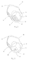
- Fig. 1 10 is a tool grip cover for an actuating tool.
- the tool handle shell 10 can be used, for example, in separating actuating tools, such as bolt cutters, mat cutters, wire mesh cutters, bolt cutters, side cutters, force side cutters, combination pliers, power packs and cable shears.
- actuating tools such as bolt cutters, mat cutters, wire mesh cutters, bolt cutters, side cutters, force side cutters, combination pliers, power packs and cable shears.
- the tool grip casing 10 with an opening 12 takes a in Fig. 1 not shown handle or handle lever of the actuating tool, also not shown, surrounds the handle or handle lever and is firmly connected thereto.
- the tool grip shell 10 consists of a plastic shell with a hard plastic component 14 and a soft plastic component 16 relative to the hard plastic components 14. In alternative embodiments, more than two plastic components with different material properties are contained in the tool grip shell 10.
- the hard plastic component 14 is used inter alia for reliable power transmission from one hand to the handle and consists of a suitable hard plastic.
- the soft plastic component 16 may e.g. consist of a rubber-like soft plastic. The soft plastic component 16 increases the grip.
- the tool grip shell 10 is slip-proof. Furthermore, the soft plastic component 16 creates a pleasant haptic perception for a user upon actuation of the tool.
- the tool handle shell 10 is ergonomically shaped and has corresponding form elements 18. This will give an optimal position and attitude of the hand and arm of the user and achieved a good concern of the tool grip shell to the hand. A secure hold and proper operation of the tool prevents accidents and reduces damaging stress on the skin and musculoskeletal system.
- a cover 20 is provided to a behind it located damping element (s. Fig. 2 to 5 ) to protect against contamination.
- the cover 20 is connected by pressing or gluing flush with the tool handle shell 10.
- the tool grip cover 10 is formed closed by a launch 22.
- the end 22 is either an integral part of the tool handle shell 10 or connected as plugged, screwed, glued or pressed cap with the tool handle shell 10. In this way, the end of the handle or handle lever is protected from damage or contamination.
- Fig. 2 the tool grip 10 is after Fig. 1 in a section along the line AB in Fig. 1 shown.
- the same components are therefore designated by corresponding reference numerals.
- Grooves 30 and webs 32 on the inner surface 34 of the tool handle shell 10 can be seen.
- the webs 32 abut against the handle or handle lever of the actuating tool and are located opposite a contact surface of a hand, on which the soft plastic component 16 is arranged on the outside of the tool grip casing 10.
- the webs 32 are formed by the hard plastic component 14 and together with the grooves 30 constitute a damping element 36. Under load, the webs 32 deform into the grooves 30 and thus absorb impacts and vibrations, such as separation impacts when disconnecting bolts or cables. Depending on the width and shape of the webs 32 a different degrees of damping is given. For example, wide webs 32 attenuate less than narrow ones.
- the webs 32 are formed by the soft plastic component 16 or consist of a soft molded plastic.
- the deformability of the soft plastic component 16 or the additionally used soft plastic increase the absorption of shocks and vibrations by the webs 32.
- the material of the webs 32 contributes substantially to the damping.
- Fig. 3 shows a further embodiment of a tool grip shell 10 with a damping element 36 in a sectional view.
- the damping element 36 is realized by nubs 38.
- the nubs are located in a recess 40 in the inner surface 34 of the tool handle shell 10 opposite the contact surface of a hand, on which the soft plastic component 16 is arranged on the outside of the tool handle shell 10.
- the faces of the nubs 38 are located on the in Fig. 3 not shown handle or handle lever of the actuating tool on.
- the nubs 38 upon loading into the recess 40 damps shocks and vibrations, e.g. a separation stroke with separating actuating tools.
- the nubs 38 are formed either by the hard plastic component 14, the soft plastic component 16 or an additional, preferably soft plastic component.
- a section of a tool grip cover 10 with a very soft plastic 42, such as a gel, as a damping element 36 is shown.
- the very soft plastic 42 is disposed in a recess 44 on the inner surface 34 of the tool handle shell 10 and is positively against the handle or the handle lever of the actuating tool.
- the very soft plastic 42 also fills the recess 44 in a form-fitting manner and is located opposite the hand-contact surface with the soft plastic component 16 on the outside of the tool grip cover 10.
- the damping element 36 is formed by the soft plastic component 16, wherein the soft plastic component 16 extends in the region of the hand contact surface of the inner surface 34 to the outer surface of the tool grip shell 10. Also in this way a damping of shocks and vibrations is achieved.
- Fig. 5 shows a section through a horriggle with a damping element 36, which includes spring elements 46.
- the spring elements 46 are made of plastic or metal or are formed as an integral part of the hard plastic component 14 or the soft plastic component 16.
- the spring elements 46 are arranged in a recess 48 of the tool grip casing 10 between a handle or handle lever of the tool and the tool grip casing 10. A part of a spring element 46 rests against the handle, while another part is carried by the tool handle cover in the region of a hand contact surface.
- the spring elements 46 dampen separation and other unwanted vibrations and shocks upon actuation of the tool.
- the spring elements 46 are configured in this embodiment as leaf springs. But it is also a use of membrane, plate, coil or coil springs as spring element 46 possible.
Landscapes
- Engineering & Computer Science (AREA)
- Mechanical Engineering (AREA)
- Scissors And Nippers (AREA)
- Harvester Elements (AREA)
- Knives (AREA)
Priority Applications (1)
| Application Number | Priority Date | Filing Date | Title |
|---|---|---|---|
| SI201031347A SI2283980T1 (sl) | 2009-08-10 | 2010-07-21 | Prijemalni ovoj orodja |
Applications Claiming Priority (1)
| Application Number | Priority Date | Filing Date | Title |
|---|---|---|---|
| DE202009010760U DE202009010760U1 (de) | 2009-08-10 | 2009-08-10 | Werkzeuggriffhülle |
Publications (3)
| Publication Number | Publication Date |
|---|---|
| EP2283980A2 true EP2283980A2 (fr) | 2011-02-16 |
| EP2283980A3 EP2283980A3 (fr) | 2014-10-22 |
| EP2283980B1 EP2283980B1 (fr) | 2016-09-21 |
Family
ID=41153171
Family Applications (1)
| Application Number | Title | Priority Date | Filing Date |
|---|---|---|---|
| EP10170259.5A Active EP2283980B1 (fr) | 2009-08-10 | 2010-07-21 | Enveloppe de poignée d'outil |
Country Status (4)
| Country | Link |
|---|---|
| EP (1) | EP2283980B1 (fr) |
| DE (1) | DE202009010760U1 (fr) |
| ES (1) | ES2607188T3 (fr) |
| SI (1) | SI2283980T1 (fr) |
Cited By (1)
| Publication number | Priority date | Publication date | Assignee | Title |
|---|---|---|---|---|
| US20150158171A1 (en) * | 2013-12-06 | 2015-06-11 | Mick B. Saunders | Slide-on grip for objects having a handle |
Families Citing this family (1)
| Publication number | Priority date | Publication date | Assignee | Title |
|---|---|---|---|---|
| DE102019102670A1 (de) * | 2019-02-04 | 2020-08-06 | Wera Werkzeuge Gmbh | Aufsteckelement |
Citations (1)
| Publication number | Priority date | Publication date | Assignee | Title |
|---|---|---|---|---|
| DE202004002614U1 (de) | 2004-02-24 | 2004-05-06 | Eduard Wille Gmbh & Co. Kg | Griffanordnung an einem Drehmomentschlüssel |
Family Cites Families (5)
| Publication number | Priority date | Publication date | Assignee | Title |
|---|---|---|---|---|
| AU8303891A (en) * | 1990-07-19 | 1992-02-18 | Cabot Safety Corporation | Vibration damping handle grip and grip cover |
| DE10348974A1 (de) * | 2003-10-22 | 2005-05-25 | Carl Freudenberg Kg | Vibrationsgedämpfter Handgriff |
| US7409747B2 (en) * | 2005-02-10 | 2008-08-12 | Shiow-Hui Chen | Pliable handle |
| DE102005055981B4 (de) * | 2005-11-22 | 2008-10-23 | Felo-Werkzeugfabrik Holland-Letz Gmbh | Handgriff für Werkzeuge und Betätigungselemente |
| EP1963072B1 (fr) * | 2005-12-23 | 2011-04-13 | Felo-Werkzeugfabrik Holland-Letz GmbH | Procede de production d'un manche |
-
2009
- 2009-08-10 DE DE202009010760U patent/DE202009010760U1/de not_active Expired - Lifetime
-
2010
- 2010-07-21 EP EP10170259.5A patent/EP2283980B1/fr active Active
- 2010-07-21 SI SI201031347A patent/SI2283980T1/sl unknown
- 2010-07-21 ES ES10170259.5T patent/ES2607188T3/es active Active
Patent Citations (1)
| Publication number | Priority date | Publication date | Assignee | Title |
|---|---|---|---|---|
| DE202004002614U1 (de) | 2004-02-24 | 2004-05-06 | Eduard Wille Gmbh & Co. Kg | Griffanordnung an einem Drehmomentschlüssel |
Cited By (1)
| Publication number | Priority date | Publication date | Assignee | Title |
|---|---|---|---|---|
| US20150158171A1 (en) * | 2013-12-06 | 2015-06-11 | Mick B. Saunders | Slide-on grip for objects having a handle |
Also Published As
| Publication number | Publication date |
|---|---|
| EP2283980A3 (fr) | 2014-10-22 |
| ES2607188T3 (es) | 2017-03-29 |
| DE202009010760U1 (de) | 2009-10-08 |
| SI2283980T1 (sl) | 2017-03-31 |
| EP2283980B1 (fr) | 2016-09-21 |
Similar Documents
| Publication | Publication Date | Title |
|---|---|---|
| EP2123406B1 (fr) | Support à vibrations amorties pour poignée supplémentaire | |
| EP1882559B1 (fr) | Outil à main doté d'un dispositif de découplage | |
| DE69507262T2 (de) | Auf schlagwerkzeugen angebrachte greif- und dämpfungsvorrichtung | |
| EP1332023A1 (fr) | Machine-outil a main comportant au moins une poignee | |
| EP2125299A1 (fr) | Manche | |
| DE202013105823U1 (de) | Leistungswerkzeug | |
| WO2011072916A1 (fr) | Machine-outil à main comportant un dispositif d'amortissement des vibrations | |
| DE2804223A1 (de) | Zusatzhandgriff fuer eine motorisch angetriebene, insbesondere axiale schlaege ausfuehrende handwerkzeugmaschine | |
| DE112014001999T5 (de) | Handgriffvorrichtung und angetriebenes Werkzeug mit derselben Handgriffvorrichtung | |
| WO2009143906A1 (fr) | Marteau perforateur et/ou burineur | |
| DE102007000408A1 (de) | Handwerkzeuggerät | |
| EP1817139B1 (fr) | Systeme de prehension de machine-outil portative pourvu d'une unite antivibrations | |
| DE102006061247A1 (de) | Handgriff | |
| EP2283980B1 (fr) | Enveloppe de poignée d'outil | |
| DE10236135B4 (de) | Tragbares, handgeführtes Werkzeug | |
| EP2750835B1 (fr) | Machine-outil portable | |
| DE102007011787A1 (de) | Handgriff | |
| WO2009043627A1 (fr) | Système de poignée supplémentaire | |
| EP2014544B1 (fr) | Poignée de bicyclette | |
| WO2009074410A1 (fr) | Poignée | |
| EP2237928A1 (fr) | Système de poignée auxiliaire | |
| WO2009077251A1 (fr) | Dispositif de préhension, en particulier dispositif de préhension de machine-outil à main | |
| EP3269518B1 (fr) | Poignee | |
| WO2008110546A1 (fr) | Poignée présentant un élément d'amortissement avec une unité d'articulation. | |
| DE102007062719A1 (de) | Zusatzhandgriffvorrichtung |
Legal Events
| Date | Code | Title | Description |
|---|---|---|---|
| PUAI | Public reference made under article 153(3) epc to a published international application that has entered the european phase |
Free format text: ORIGINAL CODE: 0009012 |
|
| AK | Designated contracting states |
Kind code of ref document: A2 Designated state(s): AL AT BE BG CH CY CZ DE DK EE ES FI FR GB GR HR HU IE IS IT LI LT LU LV MC MK MT NL NO PL PT RO SE SI SK SM TR |
|
| AX | Request for extension of the european patent |
Extension state: BA ME RS |
|
| PUAL | Search report despatched |
Free format text: ORIGINAL CODE: 0009013 |
|
| AK | Designated contracting states |
Kind code of ref document: A3 Designated state(s): AL AT BE BG CH CY CZ DE DK EE ES FI FR GB GR HR HU IE IS IT LI LT LU LV MC MK MT NL NO PL PT RO SE SI SK SM TR |
|
| AX | Request for extension of the european patent |
Extension state: BA ME RS |
|
| RIC1 | Information provided on ipc code assigned before grant |
Ipc: B25G 1/10 20060101AFI20140916BHEP Ipc: B25G 1/01 20060101ALI20140916BHEP |
|
| 17P | Request for examination filed |
Effective date: 20150422 |
|
| RBV | Designated contracting states (corrected) |
Designated state(s): AL AT BE BG CH CY CZ DE DK EE ES FI FR GB GR HR HU IE IS IT LI LT LU LV MC MK MT NL NO PL PT RO SE SI SK SM TR |
|
| 17Q | First examination report despatched |
Effective date: 20150723 |
|
| GRAP | Despatch of communication of intention to grant a patent |
Free format text: ORIGINAL CODE: EPIDOSNIGR1 |
|
| INTG | Intention to grant announced |
Effective date: 20160304 |
|
| GRAS | Grant fee paid |
Free format text: ORIGINAL CODE: EPIDOSNIGR3 |
|
| GRAA | (expected) grant |
Free format text: ORIGINAL CODE: 0009210 |
|
| RAP1 | Party data changed (applicant data changed or rights of an application transferred) |
Owner name: STAHLWILLE EDUARD WILLE GMBH & CO. KG |
|
| AK | Designated contracting states |
Kind code of ref document: B1 Designated state(s): AL AT BE BG CH CY CZ DE DK EE ES FI FR GB GR HR HU IE IS IT LI LT LU LV MC MK MT NL NO PL PT RO SE SI SK SM TR |
|
| REG | Reference to a national code |
Ref country code: GB Ref legal event code: FG4D Free format text: NOT ENGLISH |
|
| REG | Reference to a national code |
Ref country code: CH Ref legal event code: EP |
|
| REG | Reference to a national code |
Ref country code: AT Ref legal event code: REF Ref document number: 830660 Country of ref document: AT Kind code of ref document: T Effective date: 20161015 |
|
| REG | Reference to a national code |
Ref country code: IE Ref legal event code: FG4D Free format text: LANGUAGE OF EP DOCUMENT: GERMAN |
|
| REG | Reference to a national code |
Ref country code: DE Ref legal event code: R096 Ref document number: 502010012432 Country of ref document: DE |
|
| REG | Reference to a national code |
Ref country code: LT Ref legal event code: MG4D Ref country code: NL Ref legal event code: MP Effective date: 20160921 |
|
| PG25 | Lapsed in a contracting state [announced via postgrant information from national office to epo] |
Ref country code: LT Free format text: LAPSE BECAUSE OF FAILURE TO SUBMIT A TRANSLATION OF THE DESCRIPTION OR TO PAY THE FEE WITHIN THE PRESCRIBED TIME-LIMIT Effective date: 20160921 Ref country code: FI Free format text: LAPSE BECAUSE OF FAILURE TO SUBMIT A TRANSLATION OF THE DESCRIPTION OR TO PAY THE FEE WITHIN THE PRESCRIBED TIME-LIMIT Effective date: 20160921 Ref country code: NO Free format text: LAPSE BECAUSE OF FAILURE TO SUBMIT A TRANSLATION OF THE DESCRIPTION OR TO PAY THE FEE WITHIN THE PRESCRIBED TIME-LIMIT Effective date: 20161221 |
|
| PG25 | Lapsed in a contracting state [announced via postgrant information from national office to epo] |
Ref country code: GR Free format text: LAPSE BECAUSE OF FAILURE TO SUBMIT A TRANSLATION OF THE DESCRIPTION OR TO PAY THE FEE WITHIN THE PRESCRIBED TIME-LIMIT Effective date: 20161222 Ref country code: LV Free format text: LAPSE BECAUSE OF FAILURE TO SUBMIT A TRANSLATION OF THE DESCRIPTION OR TO PAY THE FEE WITHIN THE PRESCRIBED TIME-LIMIT Effective date: 20160921 Ref country code: SE Free format text: LAPSE BECAUSE OF FAILURE TO SUBMIT A TRANSLATION OF THE DESCRIPTION OR TO PAY THE FEE WITHIN THE PRESCRIBED TIME-LIMIT Effective date: 20160921 Ref country code: NL Free format text: LAPSE BECAUSE OF FAILURE TO SUBMIT A TRANSLATION OF THE DESCRIPTION OR TO PAY THE FEE WITHIN THE PRESCRIBED TIME-LIMIT Effective date: 20160921 |
|
| PG25 | Lapsed in a contracting state [announced via postgrant information from national office to epo] |
Ref country code: EE Free format text: LAPSE BECAUSE OF FAILURE TO SUBMIT A TRANSLATION OF THE DESCRIPTION OR TO PAY THE FEE WITHIN THE PRESCRIBED TIME-LIMIT Effective date: 20160921 Ref country code: RO Free format text: LAPSE BECAUSE OF FAILURE TO SUBMIT A TRANSLATION OF THE DESCRIPTION OR TO PAY THE FEE WITHIN THE PRESCRIBED TIME-LIMIT Effective date: 20160921 |
|
| PG25 | Lapsed in a contracting state [announced via postgrant information from national office to epo] |
Ref country code: CZ Free format text: LAPSE BECAUSE OF FAILURE TO SUBMIT A TRANSLATION OF THE DESCRIPTION OR TO PAY THE FEE WITHIN THE PRESCRIBED TIME-LIMIT Effective date: 20160921 Ref country code: SM Free format text: LAPSE BECAUSE OF FAILURE TO SUBMIT A TRANSLATION OF THE DESCRIPTION OR TO PAY THE FEE WITHIN THE PRESCRIBED TIME-LIMIT Effective date: 20160921 Ref country code: PT Free format text: LAPSE BECAUSE OF FAILURE TO SUBMIT A TRANSLATION OF THE DESCRIPTION OR TO PAY THE FEE WITHIN THE PRESCRIBED TIME-LIMIT Effective date: 20170123 Ref country code: BG Free format text: LAPSE BECAUSE OF FAILURE TO SUBMIT A TRANSLATION OF THE DESCRIPTION OR TO PAY THE FEE WITHIN THE PRESCRIBED TIME-LIMIT Effective date: 20161221 Ref country code: SK Free format text: LAPSE BECAUSE OF FAILURE TO SUBMIT A TRANSLATION OF THE DESCRIPTION OR TO PAY THE FEE WITHIN THE PRESCRIBED TIME-LIMIT Effective date: 20160921 Ref country code: IS Free format text: LAPSE BECAUSE OF FAILURE TO SUBMIT A TRANSLATION OF THE DESCRIPTION OR TO PAY THE FEE WITHIN THE PRESCRIBED TIME-LIMIT Effective date: 20170121 Ref country code: PL Free format text: LAPSE BECAUSE OF FAILURE TO SUBMIT A TRANSLATION OF THE DESCRIPTION OR TO PAY THE FEE WITHIN THE PRESCRIBED TIME-LIMIT Effective date: 20160921 |
|
| REG | Reference to a national code |
Ref country code: DE Ref legal event code: R097 Ref document number: 502010012432 Country of ref document: DE |
|
| REG | Reference to a national code |
Ref country code: FR Ref legal event code: PLFP Year of fee payment: 8 |
|
| PLBE | No opposition filed within time limit |
Free format text: ORIGINAL CODE: 0009261 |
|
| STAA | Information on the status of an ep patent application or granted ep patent |
Free format text: STATUS: NO OPPOSITION FILED WITHIN TIME LIMIT |
|
| PG25 | Lapsed in a contracting state [announced via postgrant information from national office to epo] |
Ref country code: DK Free format text: LAPSE BECAUSE OF FAILURE TO SUBMIT A TRANSLATION OF THE DESCRIPTION OR TO PAY THE FEE WITHIN THE PRESCRIBED TIME-LIMIT Effective date: 20160921 |
|
| 26N | No opposition filed |
Effective date: 20170622 |
|
| REG | Reference to a national code |
Ref country code: CH Ref legal event code: PL |
|
| REG | Reference to a national code |
Ref country code: IE Ref legal event code: MM4A |
|
| PG25 | Lapsed in a contracting state [announced via postgrant information from national office to epo] |
Ref country code: CH Free format text: LAPSE BECAUSE OF NON-PAYMENT OF DUE FEES Effective date: 20170731 Ref country code: LI Free format text: LAPSE BECAUSE OF NON-PAYMENT OF DUE FEES Effective date: 20170731 Ref country code: IE Free format text: LAPSE BECAUSE OF NON-PAYMENT OF DUE FEES Effective date: 20170721 |
|
| REG | Reference to a national code |
Ref country code: BE Ref legal event code: MM Effective date: 20170731 |
|
| PG25 | Lapsed in a contracting state [announced via postgrant information from national office to epo] |
Ref country code: LU Free format text: LAPSE BECAUSE OF NON-PAYMENT OF DUE FEES Effective date: 20170721 |
|
| REG | Reference to a national code |
Ref country code: FR Ref legal event code: PLFP Year of fee payment: 9 |
|
| PG25 | Lapsed in a contracting state [announced via postgrant information from national office to epo] |
Ref country code: BE Free format text: LAPSE BECAUSE OF NON-PAYMENT OF DUE FEES Effective date: 20170731 |
|
| PG25 | Lapsed in a contracting state [announced via postgrant information from national office to epo] |
Ref country code: MT Free format text: LAPSE BECAUSE OF FAILURE TO SUBMIT A TRANSLATION OF THE DESCRIPTION OR TO PAY THE FEE WITHIN THE PRESCRIBED TIME-LIMIT Effective date: 20160921 |
|
| PG25 | Lapsed in a contracting state [announced via postgrant information from national office to epo] |
Ref country code: AL Free format text: LAPSE BECAUSE OF FAILURE TO SUBMIT A TRANSLATION OF THE DESCRIPTION OR TO PAY THE FEE WITHIN THE PRESCRIBED TIME-LIMIT Effective date: 20160921 |
|
| PGFP | Annual fee paid to national office [announced via postgrant information from national office to epo] |
Ref country code: AL Payment date: 20160415 Year of fee payment: 7 Ref country code: FR Payment date: 20180723 Year of fee payment: 9 Ref country code: ES Payment date: 20180829 Year of fee payment: 9 |
|
| PGFP | Annual fee paid to national office [announced via postgrant information from national office to epo] |
Ref country code: AT Payment date: 20180719 Year of fee payment: 9 Ref country code: SI Payment date: 20180705 Year of fee payment: 9 Ref country code: GB Payment date: 20180725 Year of fee payment: 9 |
|
| PG25 | Lapsed in a contracting state [announced via postgrant information from national office to epo] |
Ref country code: HU Free format text: LAPSE BECAUSE OF FAILURE TO SUBMIT A TRANSLATION OF THE DESCRIPTION OR TO PAY THE FEE WITHIN THE PRESCRIBED TIME-LIMIT; INVALID AB INITIO Effective date: 20100721 Ref country code: MC Free format text: LAPSE BECAUSE OF FAILURE TO SUBMIT A TRANSLATION OF THE DESCRIPTION OR TO PAY THE FEE WITHIN THE PRESCRIBED TIME-LIMIT Effective date: 20160921 |
|
| PG25 | Lapsed in a contracting state [announced via postgrant information from national office to epo] |
Ref country code: CY Free format text: LAPSE BECAUSE OF NON-PAYMENT OF DUE FEES Effective date: 20160921 |
|
| PG25 | Lapsed in a contracting state [announced via postgrant information from national office to epo] |
Ref country code: MK Free format text: LAPSE BECAUSE OF FAILURE TO SUBMIT A TRANSLATION OF THE DESCRIPTION OR TO PAY THE FEE WITHIN THE PRESCRIBED TIME-LIMIT Effective date: 20160921 |
|
| REG | Reference to a national code |
Ref country code: AT Ref legal event code: MM01 Ref document number: 830660 Country of ref document: AT Kind code of ref document: T Effective date: 20190721 |
|
| GBPC | Gb: european patent ceased through non-payment of renewal fee |
Effective date: 20190721 |
|
| PG25 | Lapsed in a contracting state [announced via postgrant information from national office to epo] |
Ref country code: TR Free format text: LAPSE BECAUSE OF FAILURE TO SUBMIT A TRANSLATION OF THE DESCRIPTION OR TO PAY THE FEE WITHIN THE PRESCRIBED TIME-LIMIT Effective date: 20160921 |
|
| REG | Reference to a national code |
Ref country code: SI Ref legal event code: KO00 Effective date: 20200310 |
|
| PG25 | Lapsed in a contracting state [announced via postgrant information from national office to epo] |
Ref country code: GB Free format text: LAPSE BECAUSE OF NON-PAYMENT OF DUE FEES Effective date: 20190721 Ref country code: AT Free format text: LAPSE BECAUSE OF NON-PAYMENT OF DUE FEES Effective date: 20190721 |
|
| PG25 | Lapsed in a contracting state [announced via postgrant information from national office to epo] |
Ref country code: SI Free format text: LAPSE BECAUSE OF NON-PAYMENT OF DUE FEES Effective date: 20190722 |
|
| PG25 | Lapsed in a contracting state [announced via postgrant information from national office to epo] |
Ref country code: FR Free format text: LAPSE BECAUSE OF NON-PAYMENT OF DUE FEES Effective date: 20190731 Ref country code: HR Free format text: LAPSE BECAUSE OF FAILURE TO SUBMIT A TRANSLATION OF THE DESCRIPTION OR TO PAY THE FEE WITHIN THE PRESCRIBED TIME-LIMIT Effective date: 20160921 |
|
| PG25 | Lapsed in a contracting state [announced via postgrant information from national office to epo] |
Ref country code: IT Free format text: LAPSE BECAUSE OF NON-PAYMENT OF DUE FEES Effective date: 20190721 |
|
| REG | Reference to a national code |
Ref country code: ES Ref legal event code: FD2A Effective date: 20201201 |
|
| PG25 | Lapsed in a contracting state [announced via postgrant information from national office to epo] |
Ref country code: ES Free format text: LAPSE BECAUSE OF NON-PAYMENT OF DUE FEES Effective date: 20190722 |
|
| PGFP | Annual fee paid to national office [announced via postgrant information from national office to epo] |
Ref country code: DE Payment date: 20250725 Year of fee payment: 16 |