EP2284027A2 - Dispositif de climatisation d'un véhicule - Google Patents
Dispositif de climatisation d'un véhicule Download PDFInfo
- Publication number
- EP2284027A2 EP2284027A2 EP10171643A EP10171643A EP2284027A2 EP 2284027 A2 EP2284027 A2 EP 2284027A2 EP 10171643 A EP10171643 A EP 10171643A EP 10171643 A EP10171643 A EP 10171643A EP 2284027 A2 EP2284027 A2 EP 2284027A2
- Authority
- EP
- European Patent Office
- Prior art keywords
- groove
- spring
- housing part
- air conditioning
- housing
- Prior art date
- Legal status (The legal status is an assumption and is not a legal conclusion. Google has not performed a legal analysis and makes no representation as to the accuracy of the status listed.)
- Withdrawn
Links
Images



Classifications
-
- B—PERFORMING OPERATIONS; TRANSPORTING
- B60—VEHICLES IN GENERAL
- B60H—ARRANGEMENTS OF HEATING, COOLING, VENTILATING OR OTHER AIR-TREATING DEVICES SPECIALLY ADAPTED FOR PASSENGER OR GOODS SPACES OF VEHICLES
- B60H1/00—Heating, cooling or ventilating devices
- B60H1/00507—Details, e.g. mounting arrangements, desaeration devices
- B60H1/00514—Details of air conditioning housings
- B60H1/00528—Connections between housing parts
-
- B—PERFORMING OPERATIONS; TRANSPORTING
- B60—VEHICLES IN GENERAL
- B60H—ARRANGEMENTS OF HEATING, COOLING, VENTILATING OR OTHER AIR-TREATING DEVICES SPECIALLY ADAPTED FOR PASSENGER OR GOODS SPACES OF VEHICLES
- B60H1/00—Heating, cooling or ventilating devices
- B60H1/00507—Details, e.g. mounting arrangements, desaeration devices
- B60H2001/00635—Air-tight sealing devices
Definitions
- the present invention relates to an automotive air conditioning system according to the preamble of claims 1, 5, 10, 12 and 14.
- Automotive air conditioning systems include a refrigerant evaporator, a blower, louvers, e.g. B. flaps, which are arranged in a housing.
- the housing is generally made of plastic and is made of several housing parts, eg. B. two or four housing parts assembled. The individual housing parts are connected to each other by means of a tongue and groove connection.
- the DE 94 20 291 U1 shows a housing of at least two composable by means of a tongue and groove housing parts for a heating or air conditioning unit in a motor vehicle with a housing part with an abutment edge with a groove-like depression and another housing part with a cam-like projection.
- the groove-like depression is mutually resiliently locked with the cam-like projection.
- the DE 81 13 742.7 U1 shows a housing for an automotive air conditioning system of at least two housing parts, wherein the housing parts are formed flat on the connecting sides and on a first housing part retaining bracket and on a second housing part locking lugs, which cooperate with the retaining clips have.
- the first housing part has on its connection side a groove into which engages a arranged on the connecting side of the second housing part spring.
- the locking lugs are formed directly on the spring and the headband formed by openings in a groove wall.
- the DE 199 43 278 A1 shows a tongue and groove connection of housing parts of a housing of an air conditioning system of a motor vehicle with a groove in one of the housing parts to be connected and a spring on the other housing part, wherein the spring is U-shaped in cross-section and in the assembled state of the housing parts U- Leg of the spring abut against side walls of the groove under pressure and the spring is formed in the connecting region of the U-legs with thinner wall thickness than the U-legs, so that the U-legs are resiliently connected to each other.
- the object of the present invention is therefore to provide an automotive air conditioning system in which the tongue and groove connection between the housing parts ensures a secure and reliable connection and sealing, even during deformations.
- an automotive air conditioning system comprising a housing of interconnected housing parts, a tongue and groove connection for connecting the housing parts with one of a first and second groove wall limited groove on a housing part and a spring on another housing part, wherein the spring is arranged for connection in the groove, wherein in the groove a sealing lip is arranged and the spring between the sealing lip and the first groove wall of the groove is arranged.
- the sealing lip makes it possible to seal the tongue and groove joint even in the case of deformations in the area of the tongue and groove joint, because the elastic sealing lip can absorb possible deformations within the tongue and groove joint, so that there is constant contact between the spring and the sealing lip is available.
- the sealing lip preferably has approximately the same length in cross-section as the rib.
- the length of the sealing lip and / or the spring is measured perpendicular to a transverse direction.
- the length of the sealing lip is at least 20% of the length of the spring in cross section. This can form a relatively large bearing surface for fluidic sealing between the sealing lip and the spring.
- the sealing lip in the non-introduced state of the spring in the groove at a distance from the second groove wall in order to bend the sealing lip during insertion of the spring in the groove to the second groove wall can.
- the distance between the second groove wall and the sealing lip also makes it possible to absorb deformations, because the geometry of the tongue and groove connection is designed so that even after the complete insertion of the spring into the groove a distance between the sealing lip and the second groove wall is present which can absorb possible deformations in the area of the tongue and groove joint.
- the sealing lip is at least partially made of an elastic material, for. B. plastic.
- the elastic properties of the sealing lip make it possible to deform within the tongue and groove joint absorb and thereby ensure a secure sealing of the tongue and groove joint even during deformation.
- the housing consists at least partially of plastic and the sealing lip by means of, preferably by means of encapsulation, attached to the first and / or second groove wall.
- the sealing lip of elastic material is previously inserted in the injection molding of the housing part in the mold for injection molding and then the sealing lip is positively connected by means of encapsulation with the plastic of the housing part.
- the sealing lip is fastened in a bottom region of the groove on the housing.
- Automotive air conditioning system comprising a housing of interconnected housing parts, a tongue and groove connection for connecting the housing parts with a limited by a first and second groove wall groove on a housing part and a spring on another housing part, wherein the spring for connection in the groove is arranged, wherein the spring before insertion of the spring into the groove in the transverse direction is greater than the groove, so that at least one groove wall in an insertion of the spring into the groove of the spring deformable, in particular bendable, is.
- the groove is increased due to the size of the spring.
- the spring between the first and second groove wall is clamped under bias.
- the bearing surface between the two groove walls and the spring is thus under pressure, so that a secure and reliable seal and connection is ensured here.
- the at least one groove wall in the transverse direction is deformable by the spring during insertion of the spring into the groove in such a way that the groove increases.
- the first groove wall has a smaller wall thickness than the second groove wall, so that essentially the first groove wall is deformable when inserting the spring into the groove.
- the spring in the transverse direction by at least 1% larger than the groove, so that the at least one groove wall deformable by at least 0.5% of the dimension of the spring in the transverse direction upon insertion of the spring into the groove of the spring, in particular bendable, is.
- first and second groove walls are aligned at an acute angle to each other, so that the groove has a wedge-shaped cross-section and / or the spring has a wedge-shaped cross-section.
- the groove and the spring are wedge-shaped in cross section, so that when inserting the spring into the groove, the two or a groove wall are pressed apart by the spring.
- Automotive air conditioning system comprising a housing of interconnected housing parts, a tongue and groove connection for connecting the housing parts with a limited by a first and second groove wall groove on a housing part and a spring on another housing part, wherein the spring for connection in the groove arranged and the spring is positively fixed in the groove, wherein the geometry of the spring and the groove are formed so that arise in cross section at least three bearing surfaces of the spring on the first and / or second groove wall and / or the groove has at least two undercuts engage in the at least two projections of the spring for positive fixing.
- Three bearing surfaces of the spring on the two groove walls or two undercuts, in which engage projections of the spring, allow a particularly secure and reliable connection between the groove and the spring.
- the spring and the first and / or second groove wall at least three flat or convex surfaces on which the spring rests on the first and / or second groove wall.
- a flat and / or a convex surface on the groove wall in the region of the groove and / or the spring makes it possible reliably and safely to obtain corresponding bearing surfaces between the spring and the first and second groove walls, which permit a continuous and complete sealing of the groove spring connection, so that in the tongue and groove connection substantially no areas occur at which no bearing surfaces are present.
- Automotive air conditioning system in particular an automotive air conditioning system described in this application, comprising a housing of interconnected housing parts, a tongue and groove connection for connecting the housing parts with a limited by a first and second groove wall groove on a housing part and a spring on another housing part, wherein the spring is arranged for connection in the groove, one arranged on the one and the other housing part clamp for connecting the one housing part with the other housing part, wherein the clip is integrally connected to a housing part.
- the clip is used for, preferably detachable, connecting the two housing parts by positive engagement and / or jamming.
- the clip is integrally formed with a housing part, so that the Clamp particularly inexpensive in the manufacture of the housing part during injection molding can be made with this.
- the clip can not be lost, because it is integrally connected to the housing part. The assembly is made much easier because only the clip still has to be pivoted from one housing part to the other housing part.
- the clip is pivotally connected by means of a film hinge with the one housing part and / or the clip is connected to the one housing part at a portion having a low material thickness, so that the clip is pivotable at the portion with the small material thickness.
- Automotive air conditioning system in particular an automotive air conditioning system described in this application, comprising a housing of interconnected housing parts, a tongue and groove connection for connecting the housing parts with a limited by a first and second groove wall groove on a housing part and a spring on another housing part, wherein the spring is arranged for connection in the groove, at least one latching nose for the positive connection of the one housing part with the other housing part, wherein the at least one latching lug is formed on an extension mandrel.
- first and / or second groove wall has a recess through which the extension mandrel is insertable and the at least one latching lug is latched to the first and / or second groove wall in the region of an outer end of the recess and / or the extension mandrel as an extension of the spring, in particular in one piece, formed.
- the locking lug is integrated in the tongue and groove connection.
- the latching connection between the two housing parts can thus be made particularly simple and it is preferably also no additional components necessary because the at least one latching lug is formed integrally with the housing part with the spring.
- the extension element disposed on the spring projects through a corresponding opening in the first and / or second groove wall or in its connection region or in the groove base of the second component and is converted into a positive connection, for example by hot riveting, after assembly of the components makes with another element a positive and / or positive connection.
- the laying and locking of the at least one latching lug is possible on the first and / or second groove wall, so that the positive connection takes place by means of the at least one latching lug in the region of the tongue and groove connection and thereby no additional space is required.
- FIG. 1 two housing parts 1 of an automotive air conditioning system are shown.
- the automotive air conditioning system includes a refrigerant evaporator, a fan and louvers, e.g. B. flaps, which are arranged in the housing (not shown).
- the housing of the motor vehicle air conditioning system comprises a first housing part 2 and a second housing part 3.
- the two housing part 2, 3 made of plastic can be connected to each other by means of a tongue and groove connection 6.
- Fig. 1 is the unconnected state between the first and second housing part 2, 3 shown and in Fig. 2 the connected state between the first and second housing part 2, 3.
- Fig. 2 is thus formed on the first housing part 2
- Spring 5 arranged in a formed on the second housing part 3 groove 4.
- the groove 4 has a bottom region 20 and two side regions 21.
- a sealing lip 9 is arranged made of an elastic material made of plastic.
- the sealing lip 9 is integrally connected in the bottom region 20 of the groove 4 by means of encapsulation with the second housing part 3.
- the length of the sealing lip 9 perpendicular to a transverse direction 11 is only slightly smaller than the length of the spring 5 perpendicular to the transverse direction 11.
- the sealing lip 9 and the spring 5 thus have approximately the same length perpendicular to the transverse direction 11.
- the groove 4 is bounded by a first groove wall 7 and a second groove wall 8.
- the sealing lip 9 is further connected to support ribs 10 with the second groove wall 8.
- the support ribs 10 are formed perpendicular to the plane of FIG. 10 approximately at a distance of 30 mm.
- the clearance between the sealing lip 9 and the first groove wall 7 is smaller than the spring 5.
- the sealing lip 9 is thus deformed in the direction of the second groove wall 8. This deformation is possible because in the non-introduced state of the spring 5 in the groove 4 as shown in FIG Fig. 1 there is a gap between the sealing lip 9 and the second groove wall 8. Even after the insertion of the spring 5 in the groove 4, there is a gap between the sealing lip 9 and the second groove wall 8. However, this distance is reduced and also the support ribs 10 are deformed.
- the spring 5 is elastically clamped or clamped between the first groove wall 7 under prestress between the sealing lip 9 and the first groove wall 7.
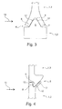
- Fig. 3 is a second embodiment of the tongue and groove connection 6 shown.
- the first and second groove walls 7, 8 are aligned with each other at an acute angle, so that the groove 4 is wedge-shaped in cross section.
- the spring 5 is wedge-shaped in cross section. In the transverse direction 11, before the spring 5 is inserted into the groove 4 (not shown), the spring 4 has larger dimensions than the groove 4.
- the two groove walls 7, 8 are pressed apart. so that the spring 5 between the two Nutwanditch 7, 8 is clamped under bias due to the elastic deformation of the two Nutwanditch 7, 8.
- the housing parts 1 are made of a plastic material having elastic properties, so that such elastic deformations of the two Nutwanditch 7, 8 possible are. Between the two Nutwanditch 7, 8 and the spring 5 thus form two bearing surfaces 12 for forming a fluid-tight connection.
- Fig. 4 is a third embodiment of the tongue and groove joint 6 shown.
- the two groove walls 7, 8 has a different thickness.
- the first groove wall 7 has a smaller thickness than the second groove wall 8.
- the groove 4 and the spring 5 in an analogous manner to the second embodiment according to Fig. 3 designed in such a way that in the transverse direction 11, the spring 5 before insertion of the spring 5 in the groove 4 has larger dimensions than the groove 4.
- the enlargement of the groove 4 is substantially of a deformation of the first Groove 7 carried out because the second groove wall 8 has a substantially greater thickness than the first groove wall 7, so that the first groove wall 7 is much easier to deform or bend than the second groove wall.
- a fourth embodiment of the tongue and groove connection 6 is shown.
- the groove 4 formed or enclosed by the first and second groove walls 7, 8 has an undercut 13 in this case.
- the right-angled undercut 13 is formed as an undercut on the first groove wall 7.
- a recess is provided on the outside between the first groove wall 7 and the second groove wall 8.
- the spring 5, which is formed integrally with the second housing part 3, has two projections 14. The two projections 14 engage in the undercut 13 and the V-shaped region on the first and / or second groove wall 7, 8.
- the first groove wall 7 For insertion of the spring 5 in the groove 4 according to the fourth embodiment, the first groove wall 7 must be pivoted to the effect that the groove 4 increases.
- the first groove wall 7 is pivoted substantially about a pivot point which lies in the region of the portion 17.
- the groove 4 increases.
- a pivoting of the first groove wall 7 is possible with relatively low forces in the region of the portion 17 with low material thickness.
- the spring 5 can be introduced into the groove 4 and subsequently the forces required for the deformation or pivoting of the first groove wall 7 no longer need to be applied to the first groove wall 7. As a result, the spring 5 is clamped under pretension between the first and second groove walls 7, 8.
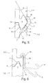
- Fig. 6 shows a fifth embodiment of the tongue and groove connection 6.
- the first housing part 2 and the second housing part 3 are connected to each other next to the tongue and groove connection 6 by means of a clamp 15.
- the clip 15 is integrally formed by means of a film hinge 16.
- the clip 15, the film hinge 16 and the first housing part 2 are made of the same material, ie plastic.
- a clamping nose 24 is present on the second housing part 3. After insertion of the spring 5 in the groove 4 must for the final and releasable connection between the first and second housing part 2, 3, only the bracket 15 of an example in Fig.
- Fig. 7 is a sixth embodiment of the tongue and groove joint 6 shown.
- the two housing parts 2, 3 are connected by a clamp 15 under bias with each other or jammed.
- the bracket 15 is formed integrally with the first housing part 2.
- a portion 17 are used with a low material thickness in a modification to the fifth embodiment instead of a film hinge 16. Otherwise corresponds to the sixth embodiment according to Fig. 7 the fifth embodiment.
- Fig. 8 is a seventh embodiment of the tongue and groove joint 6 shown.
- an extension mandrel 19 is integral with the first housing part 2, at the end of two locking lugs 18 are present.
- cylindrical recesses 23 are present between the first groove wall 7 and the second groove wall 8 .
- the cylindrical recesses 23 are, for example, at a distance of 30 mm perpendicular to the plane according to Fig. 8 formed between the first and second groove wall 7, 8.
- the recesses 23 are slit-shaped running.
- the two locking lugs 18, the extension mandrel 19, the spring 5 and the first housing part 2 consist of an elastic Plastic.
- the extension mandrel 19 is also introduced with the locking lugs 18 in the cylindrical recess 23.
- the two locking lugs 18 are larger than the recess 23 so that they deform due to their elastic properties during insertion into the recess 23 and two locking lugs 18 can be passed through the recess 23.
- the two locking lugs 18 deform again into their original shape, the in Fig. 8 is shown.
- this compound is under bias.
- the first and second housing part 2, 3 is thus reliably connected, so that there is substantially no danger that the two housing parts 2, 3 separate from each other.
- Fig. 9 is an eighth embodiment of the tongue and groove joint 6 similar to that in Figure 5 illustrated embodiment illustrated.
- the groove 4 formed or enclosed by the first and second groove walls 7, 8 has two undercuts 13.
- the first in Fig. 9 The right-angled undercut 13 is formed as an undercut on the first groove wall 7.
- the second undercut 13, in Fig. 9 shown below, is between the first and the second groove wall 7, 8 available.
- the wall thickness of the second groove wall 8 decreases from the upper end region to the connection region of the first groove wall 7, resulting in a wedge-shaped contour.
- Below the second undercut 13 is as in Figure 5 a section 17 with a low material thickness available.
- the first with the second housing part 2, 3 in addition to the tongue and groove connection 6 are connected to a rivet or a screw together.
- a recess 23 is present between the first and second housing part 2, 3.
- this recess 23 is present in the region of the tongue and groove connection 6.
- a bracket 15 has a web, at the ends of each transverse webs are formed, so that the ends of the web are T-shaped.
- this clip 15 is inserted, wherein the web is only slightly smaller than the recess 23.
- the T-shaped webs are deformed due to their elastic properties, so that the T-shaped ends can be performed through the recess 23. After passing through the two T-shaped ends of the web engage behind the first and second housing part 2, 3, so that thereby the two housing parts 2, 3 are positively connected with each other.
- a connecting pin is formed on a housing part 1.
- a recess is present, in which the connection mandrel 2, 3 is introduced with each other when connecting the two housing parts.
- the connecting mandrel is slightly beyond the recess and is there z. B. by welding or hot riveting to the housing part positively and / or non-positively connected.
- the connecting mandrel and the two housing parts are made of plastic. Instead of the described welding, the connecting mandrel can also be connected to the housing part by means of a spring washer.
- the spring washer is pushed onto the connecting mandrel, which protrudes through the recess after the connection.
- the spring washer is, for example, plate-shaped and has a centric one Hole on. To the central bore radial slots are arranged, which allow deformation of the spring washer.
- mandrels are present, which engage in corresponding recesses.
- the mandrels serve for additional alignment of the tongue and groove connection.
Landscapes
- Physics & Mathematics (AREA)
- Thermal Sciences (AREA)
- Engineering & Computer Science (AREA)
- Mechanical Engineering (AREA)
- Air-Conditioning For Vehicles (AREA)
- Motor Or Generator Frames (AREA)
- Gasket Seals (AREA)
Applications Claiming Priority (1)
| Application Number | Priority Date | Filing Date | Title |
|---|---|---|---|
| DE102009037304A DE102009037304A1 (de) | 2009-08-14 | 2009-08-14 | Kraftfahrzeugklimaanlage |
Publications (2)
| Publication Number | Publication Date |
|---|---|
| EP2284027A2 true EP2284027A2 (fr) | 2011-02-16 |
| EP2284027A3 EP2284027A3 (fr) | 2011-08-03 |
Family
ID=42735396
Family Applications (1)
| Application Number | Title | Priority Date | Filing Date |
|---|---|---|---|
| EP10171643A Withdrawn EP2284027A3 (fr) | 2009-08-14 | 2010-08-02 | Dispositif de climatisation d'un véhicule |
Country Status (2)
| Country | Link |
|---|---|
| EP (1) | EP2284027A3 (fr) |
| DE (1) | DE102009037304A1 (fr) |
Cited By (1)
| Publication number | Priority date | Publication date | Assignee | Title |
|---|---|---|---|---|
| US9809084B2 (en) | 2011-12-19 | 2017-11-07 | Mahle International Gmbh | Housing particularly for a motor vehicle HVAC system |
Families Citing this family (3)
| Publication number | Priority date | Publication date | Assignee | Title |
|---|---|---|---|---|
| CN104482643A (zh) * | 2014-12-30 | 2015-04-01 | 博耐尔汽车电气系统有限公司 | 一种汽车空调hvac壳体卡合紧固结构 |
| DE102015108733A1 (de) * | 2015-06-02 | 2016-12-08 | Kiekert Ag | Kraftfahrzeugschloss |
| DE102020208560A1 (de) | 2020-07-08 | 2022-01-13 | Mahle International Gmbh | Gehäuse |
Family Cites Families (13)
| Publication number | Priority date | Publication date | Assignee | Title |
|---|---|---|---|---|
| DE8113742U1 (de) | 1981-05-09 | 1981-08-06 | Süddeutsche Kühlerfabrik Julius Fr. Behr GmbH & Co KG, 7000 Stuttgart | Gehäuse für eine Kraftfahrzeug-Klima-, Heizungs- und/oder Belüftungsanlage |
| JPS60143010U (ja) * | 1984-03-05 | 1985-09-21 | 三菱電機株式会社 | 自動車用空気調和装置のケ−シング |
| FR2707953B1 (fr) * | 1993-07-22 | 1995-08-25 | Valeo Thermique Habitacle | Procédé pour coupler deux parties d'un boîtier, et boîtiers s'y rapportant, notamment pour installation de climatisation, chauffage et/ou ventilation d'automobile. |
| DE9420291U1 (de) | 1994-12-19 | 1995-10-19 | Siemens AG, 80333 München | Gehäuse aus zumindest zwei mittels einer Nut-Feder-Verbindung zusammensetzbaren Gehäuseteilen |
| FR2777862B1 (fr) * | 1998-04-22 | 2000-06-30 | Valeo Climatisation | Boitier demontable pour equipement de vehicule automobile |
| DE19943278A1 (de) | 1999-09-10 | 2001-03-15 | Behr Gmbh & Co | Nut-Federverbindung von Gehäuseteilen eines Gehäuses einer Belüftungs-, Heizungs-, oder Klimaanlage eines Kraftfahrzeuges |
| JP4075681B2 (ja) * | 2003-05-09 | 2008-04-16 | 株式会社デンソー | ケース結合構造 |
| US7036825B2 (en) * | 2003-08-26 | 2006-05-02 | Delphi Technologies, Inc. | Integrally molded lateral compression seal |
| DE50306317D1 (de) * | 2003-09-03 | 2007-03-08 | Frape Behr Sa | Rastverbindung von Gehäuseteilen |
| DE102004007283A1 (de) * | 2004-02-14 | 2005-09-01 | Daimlerchrysler Ag | Luftansauggehäuse einer Klimaanlage und/oder Heizung eines Kraftfahrzeugs |
| JP4600338B2 (ja) * | 2005-11-09 | 2010-12-15 | 株式会社デンソー | 空調装置 |
| DE102007012519A1 (de) * | 2007-03-15 | 2008-09-18 | Valeo Klimasysteme Gmbh | Luftführungsgehäuse |
| EP2062761B1 (fr) * | 2007-11-26 | 2011-02-16 | Behr GmbH & Co. KG | Dispositif de climatisation de véhicule automobile |
-
2009
- 2009-08-14 DE DE102009037304A patent/DE102009037304A1/de not_active Withdrawn
-
2010
- 2010-08-02 EP EP10171643A patent/EP2284027A3/fr not_active Withdrawn
Cited By (1)
| Publication number | Priority date | Publication date | Assignee | Title |
|---|---|---|---|---|
| US9809084B2 (en) | 2011-12-19 | 2017-11-07 | Mahle International Gmbh | Housing particularly for a motor vehicle HVAC system |
Also Published As
| Publication number | Publication date |
|---|---|
| DE102009037304A1 (de) | 2011-02-17 |
| EP2284027A3 (fr) | 2011-08-03 |
Similar Documents
| Publication | Publication Date | Title |
|---|---|---|
| DE102009024983B4 (de) | Verbindungsbaugruppe | |
| DE10159380B4 (de) | Verbindungsmutter zum Anschrauben von Konstruktionselementen an einem plattenartigen Bauteil | |
| EP1840437B1 (fr) | Dispositif d'étanchéité pour un raccord rapide | |
| EP1681504A2 (fr) | Raccord de liaison de deux conduites | |
| EP2147813A2 (fr) | Agencement d'une vitre fixe sur un flanc de carrosserie, ainsi que clip de fixation destiné au montage de la vitre fixe | |
| WO2002086339A1 (fr) | Joint a angles | |
| DE102013109233A1 (de) | Verbinder | |
| DE69212963T2 (de) | Selbstspannende Klemme | |
| DE102014104206A1 (de) | Befestigungsclip und Verfahren zum Herstellen eines Befestigungsclips | |
| EP2284027A2 (fr) | Dispositif de climatisation d'un véhicule | |
| DE102005006884A1 (de) | Kugelgelenk | |
| EP3652450A1 (fr) | Connecteur, système composé d'un connecteur et d'une tige d'encliquetage contenant une tête d'un deuxième composant, procédé utilisant un tel système | |
| DE102010004686A1 (de) | Rastverbindungsmittel für eine Baugruppe | |
| DE102013107525A1 (de) | Flanschanschlusssystem | |
| EP3751081A1 (fr) | Charnière de montage rapide ainsi qu'armoire en tôle dotée de la charnière de montage rapide | |
| EP2682555B1 (fr) | Elément de liaison d'angle | |
| WO2005095842A1 (fr) | Raccord enfichable a blocage angulaire | |
| DE102025102321A1 (de) | Befestigungsvorrichtung, insbesondere ein Kantenclip, zum Befestigen eines ersten Bauteils an einem zweiten Bauteil | |
| DE102018107507A1 (de) | "Anschlussvorrichtung für Medienleitungen" | |
| DE69027861T2 (de) | Schnellverriegelungsverbindung durch einrastmechanismus | |
| AT522362B1 (de) | Halterung für die lösbare Befestigung eines Schilds | |
| DE102013100308A1 (de) | Riegelstangenbeschlag für ein Fenster oder eine Tür | |
| EP2336662B1 (fr) | Elément de liaison pour relier deux canaux d'aération | |
| DE4428572C2 (de) | Rohrkupplung | |
| DE20105250U1 (de) | Flachdichtung |
Legal Events
| Date | Code | Title | Description |
|---|---|---|---|
| PUAI | Public reference made under article 153(3) epc to a published international application that has entered the european phase |
Free format text: ORIGINAL CODE: 0009012 |
|
| AK | Designated contracting states |
Kind code of ref document: A2 Designated state(s): AL AT BE BG CH CY CZ DE DK EE ES FI FR GB GR HR HU IE IS IT LI LT LU LV MC MK MT NL NO PL PT RO SE SI SK SM TR |
|
| AX | Request for extension of the european patent |
Extension state: BA ME RS |
|
| PUAL | Search report despatched |
Free format text: ORIGINAL CODE: 0009013 |
|
| AK | Designated contracting states |
Kind code of ref document: A3 Designated state(s): AL AT BE BG CH CY CZ DE DK EE ES FI FR GB GR HR HU IE IS IT LI LT LU LV MC MK MT NL NO PL PT RO SE SI SK SM TR |
|
| AX | Request for extension of the european patent |
Extension state: BA ME RS |
|
| RIC1 | Information provided on ipc code assigned before grant |
Ipc: B60H 1/00 20060101AFI20110627BHEP |
|
| 17P | Request for examination filed |
Effective date: 20120203 |
|
| 17Q | First examination report despatched |
Effective date: 20140811 |
|
| RAP1 | Party data changed (applicant data changed or rights of an application transferred) |
Owner name: MAHLE BEHR GMBH & CO. KG |
|
| GRAP | Despatch of communication of intention to grant a patent |
Free format text: ORIGINAL CODE: EPIDOSNIGR1 |
|
| INTG | Intention to grant announced |
Effective date: 20180508 |
|
| STAA | Information on the status of an ep patent application or granted ep patent |
Free format text: STATUS: THE APPLICATION IS DEEMED TO BE WITHDRAWN |
|
| 18D | Application deemed to be withdrawn |
Effective date: 20180919 |