EP2284046A1 - Stossfänger zur Verringerung der Verletzungen von Fussgängern - Google Patents
Stossfänger zur Verringerung der Verletzungen von Fussgängern Download PDFInfo
- Publication number
- EP2284046A1 EP2284046A1 EP10012116A EP10012116A EP2284046A1 EP 2284046 A1 EP2284046 A1 EP 2284046A1 EP 10012116 A EP10012116 A EP 10012116A EP 10012116 A EP10012116 A EP 10012116A EP 2284046 A1 EP2284046 A1 EP 2284046A1
- Authority
- EP
- European Patent Office
- Prior art keywords
- impact
- energy absorber
- during
- bumper
- vehicle
- Prior art date
- Legal status (The legal status is an assumption and is not a legal conclusion. Google has not performed a legal analysis and makes no representation as to the accuracy of the status listed.)
- Granted
Links
Images


Classifications
-
- B—PERFORMING OPERATIONS; TRANSPORTING
- B60—VEHICLES IN GENERAL
- B60R—VEHICLES, VEHICLE FITTINGS, OR VEHICLE PARTS, NOT OTHERWISE PROVIDED FOR
- B60R19/00—Wheel guards; Radiator guards, e.g. grilles; Obstruction removers; Fittings damping bouncing force in collisions
- B60R19/02—Bumpers, i.e. impact receiving or absorbing members for protecting vehicles or fending off blows from other vehicles or objects
- B60R19/18—Bumpers, i.e. impact receiving or absorbing members for protecting vehicles or fending off blows from other vehicles or objects characterised by the cross-section; Means within the bumper to absorb impact
-
- B—PERFORMING OPERATIONS; TRANSPORTING
- B60—VEHICLES IN GENERAL
- B60R—VEHICLES, VEHICLE FITTINGS, OR VEHICLE PARTS, NOT OTHERWISE PROVIDED FOR
- B60R21/00—Arrangements or fittings on vehicles for protecting or preventing injuries to occupants or pedestrians in case of accidents or other traffic risks
- B60R21/34—Protecting non-occupants of a vehicle, e.g. pedestrians
-
- B—PERFORMING OPERATIONS; TRANSPORTING
- B60—VEHICLES IN GENERAL
- B60R—VEHICLES, VEHICLE FITTINGS, OR VEHICLE PARTS, NOT OTHERWISE PROVIDED FOR
- B60R19/00—Wheel guards; Radiator guards, e.g. grilles; Obstruction removers; Fittings damping bouncing force in collisions
- B60R19/02—Bumpers, i.e. impact receiving or absorbing members for protecting vehicles or fending off blows from other vehicles or objects
- B60R19/24—Arrangements for mounting bumpers on vehicles
- B60R19/26—Arrangements for mounting bumpers on vehicles comprising yieldable mounting means
-
- B—PERFORMING OPERATIONS; TRANSPORTING
- B60—VEHICLES IN GENERAL
- B60R—VEHICLES, VEHICLE FITTINGS, OR VEHICLE PARTS, NOT OTHERWISE PROVIDED FOR
- B60R19/00—Wheel guards; Radiator guards, e.g. grilles; Obstruction removers; Fittings damping bouncing force in collisions
- B60R19/02—Bumpers, i.e. impact receiving or absorbing members for protecting vehicles or fending off blows from other vehicles or objects
- B60R19/18—Bumpers, i.e. impact receiving or absorbing members for protecting vehicles or fending off blows from other vehicles or objects characterised by the cross-section; Means within the bumper to absorb impact
- B60R2019/1806—Structural beams therefor, e.g. shock-absorbing
-
- B—PERFORMING OPERATIONS; TRANSPORTING
- B60—VEHICLES IN GENERAL
- B60R—VEHICLES, VEHICLE FITTINGS, OR VEHICLE PARTS, NOT OTHERWISE PROVIDED FOR
- B60R19/00—Wheel guards; Radiator guards, e.g. grilles; Obstruction removers; Fittings damping bouncing force in collisions
- B60R19/02—Bumpers, i.e. impact receiving or absorbing members for protecting vehicles or fending off blows from other vehicles or objects
- B60R19/18—Bumpers, i.e. impact receiving or absorbing members for protecting vehicles or fending off blows from other vehicles or objects characterised by the cross-section; Means within the bumper to absorb impact
- B60R2019/186—Additional energy absorbing means supported on bumber beams, e.g. cellular structures or material
- B60R2019/1866—Cellular structures
-
- B—PERFORMING OPERATIONS; TRANSPORTING
- B60—VEHICLES IN GENERAL
- B60R—VEHICLES, VEHICLE FITTINGS, OR VEHICLE PARTS, NOT OTHERWISE PROVIDED FOR
- B60R19/00—Wheel guards; Radiator guards, e.g. grilles; Obstruction removers; Fittings damping bouncing force in collisions
- B60R19/02—Bumpers, i.e. impact receiving or absorbing members for protecting vehicles or fending off blows from other vehicles or objects
- B60R19/18—Bumpers, i.e. impact receiving or absorbing members for protecting vehicles or fending off blows from other vehicles or objects characterised by the cross-section; Means within the bumper to absorb impact
- B60R2019/186—Additional energy absorbing means supported on bumber beams, e.g. cellular structures or material
- B60R2019/188—Blow molded structures
-
- B—PERFORMING OPERATIONS; TRANSPORTING
- B60—VEHICLES IN GENERAL
- B60R—VEHICLES, VEHICLE FITTINGS, OR VEHICLE PARTS, NOT OTHERWISE PROVIDED FOR
- B60R19/00—Wheel guards; Radiator guards, e.g. grilles; Obstruction removers; Fittings damping bouncing force in collisions
- B60R19/02—Bumpers, i.e. impact receiving or absorbing members for protecting vehicles or fending off blows from other vehicles or objects
- B60R19/24—Arrangements for mounting bumpers on vehicles
- B60R2019/247—Fastening of bumpers' side ends
-
- B—PERFORMING OPERATIONS; TRANSPORTING
- B60—VEHICLES IN GENERAL
- B60R—VEHICLES, VEHICLE FITTINGS, OR VEHICLE PARTS, NOT OTHERWISE PROVIDED FOR
- B60R21/00—Arrangements or fittings on vehicles for protecting or preventing injuries to occupants or pedestrians in case of accidents or other traffic risks
- B60R2021/0002—Type of accident
- B60R2021/0009—Oblique collision
-
- B—PERFORMING OPERATIONS; TRANSPORTING
- B60—VEHICLES IN GENERAL
- B60R—VEHICLES, VEHICLE FITTINGS, OR VEHICLE PARTS, NOT OTHERWISE PROVIDED FOR
- B60R21/00—Arrangements or fittings on vehicles for protecting or preventing injuries to occupants or pedestrians in case of accidents or other traffic risks
- B60R21/34—Protecting non-occupants of a vehicle, e.g. pedestrians
- B60R2021/343—Protecting non-occupants of a vehicle, e.g. pedestrians using deformable body panel, bodywork or components
Definitions
- the present invention relates to bumpers for passenger vehicles designed to reduce pedestrian injury upon impact, and more particularly relates to a bumper having an energy absorber optimized to provide a relatively soft initial impact and a "throwing" force after initial impact to a pedestrian struck by the bumper.
- Automotive bumper systems in the United States have been designed for resistance to damage at low and high vehicle speeds and for high-energy absorption at high impact speeds. Recently, pedestrian safety has begun to receive increasing attention.
- design of bumpers for pedestrian safety is complicated by several conflicting functional requirements.
- the human body cannot withstand high-energy impacts nor sharp impacts without substantial damage to muscle and bone tissue.
- it is difficult to reduce the magnitude and rate of energy transfer from a bumper to a pedestrian upon impact, especially immediate transfer of energy from a "sharp" impact because vehicle bumpers are usually limited to a relatively short stroke by components behind the bumper, such as a radiator and other engine components, and also limited by other front-end components and supporting structure. This is especially true of smaller and more compact vehicles.
- the bumpers must be made of strong materials in order to maintain their shape and appearance over time, and to provide their primary function of being a "bumper" for the vehicle to push away items and to prevent damage to the vehicle.
- the problems are further complicated by aerodynamic designs, where corners of the bumper system are swept and curved back into the vehicle fenders, which further limits bumpers strokes and the bumper's ability to collapse or flex.
- the problem is compounded by the fact that bumpers are at knee-height, such that pedestrian-related vehicular accidents often involve trauma to the pedestrian's knees. Joints and exposed bones are particularly prone to injury upon impact.
- a bumper system is desired solving the aforementioned problems and having the aforementioned advantages.
- a bumper system for a vehicle includes a beam adapted for attachment to a vehicle, and an energy absorber engaging a face of the beam.
- the energy absorber has a top horizontal section defined by a top wall and an upper-mid wall connected by an upper-front wall, and also has a bottom horizontal section defined by a bottom wall and a lower-mid wall connected by a lower-front wall, and still further has a middle horizontal section defined by a mid-front wall connecting the upper-mid wall and the lower-mid wall.
- the top and bottom horizontal sections include top and bottom front nose portions that extend forward of the mid-front wall and that define a horizontal channel therebetween in front of the mid-front wall.
- the front nose portions are configured to provide a first level of energy absorption during an initial impact stroke that collapses one or both of the front nose portions, with the top, middle, and bottom horizontal sections providing a higher second level of energy absorption during a continuing impact stroke that collapses the energy absorber against the face of the beam.
- a fascia covers the energy absorber and the beam.
- a bumper system for a vehicle in another aspect of the present invention, includes a beam adapted for attachment to a vehicle and having a longitudinal curvature that, when viewed from above in a vehicle-mounted position, is shaped to match an aerodynamic curvilinear shape of a front of the vehicle.
- the bumper system further includes an energy absorber engaging a face of the beam.
- the energy absorber has a top horizontal section defined by a top wall and an upper-mid wall connected by an upper-front wall, and has a bottom horizontal section defined by a bottom wall and a lower-mid wall connected by a lower-front wall, such that the top and bottom horizontal sections including top and bottom front nose portions that extend forwardly.
- the top and bottom nose portions each are semi-rigid but are collapsible with a parallelogram motion that shifts one or both of the top and bottom front walls vertically, such that horizontal impact forces are converted at least in part to a vertical force upon receiving a horizontal frontal impact during an initial stroke of the frontal impact.
- the top and bottom front nose portions provide a relatively low-energy absorption that "catches" an impacted object such as a knee of a human being, and then during a further continuing impact stroke, the top and bottom horizontal sections crush to provide an increased energy absorption.
- a bumper system for a vehicle includes a beam adapted for attachment to a vehicle and having a curvilinear longitudinal shape when viewed from above in a vehicle-mounted position, the beam including mounts positioned at ends of the beam.
- An energy absorber engages a face of the beam.
- the energy absorber has a middle section engaging the face and further has end sections that extend outwardly from the middle section and at least partially around the associated ends of the beam.
- the end sections ach have an enlarged free end portion and a transition portion connecting the free end portion to an end of the middle section.
- Each of the transition portions of the end sections of the energy absorber are constructed to provide a relatively low-energy absorption and further are configured to torsionally crush so that the enlarged free end portion swings rearward and "catches" an impacted object such as a knee of a human being, and then during a further continuing part of the bumper stroke, the transition portion provides increased energy absorption and counteractive forces such that the free end portion pushes the impacted object away both due to lateral resistive forces developed in the energy absorber non parallel a line of impact and also due to sliding of the impacted object along an inclined surface of the free end portion.
- a method comprises steps of constructing a bumper system including a stiff beam, and an energy absorber on a face of the beam.
- the energy absorber has top, middle, and bottom sections, with the top and bottom sections defining nose portions that extend forward of the middle section.
- the nose sections define a space therebetween in front of the middle section, the top and bottom nose sections being constructed to deflect with a parallelogram motion upon impact and that shift at least one of the nose portions vertically with a parallelogram motion in response to an impact directed horizontally against a front of the bumper system, whereby energy directed against a knee of an impacted person is converted into a throwing force that directs the person in a direction generally perpendicular to the line of impact and away from the vehicle bumper system.
- the objects of the present invention include providing a bumper system adapted to initially "catch” a person during an initial phase of impact, with less energy and forces being transmitted to the person and/or the forces being transmitted at a slower rate during the initial phase, and hence less injury being likely.
- the objects further include reorienting the impact forces transmitted to the person from a line parallel the direction of impact to a direction upward or downward (in the case of a front impact) or laterally (in the case of a corner impact). By these actions, the impacted person is initially “caught” and then “thrown” in a direction away from the line of impact, thus reducing injury and also reducing damage to the vehicle bumper system.
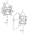
- a vehicle bumper system 20 ( Figs. 1-2 ) includes a beam 21, and an energy absorber 22 with top and bottom horizontal sections 23, 24, and a middle horizontal section 25.
- the top and bottom horizontal sections 23-24 form top and bottom nose portions 26 and 27 that are semi-rigid but collapsible with a parallelogram motion that shifts the top and bottom portions 26 and 27 vertically up (or down) upon impact.
- horizontal impact forces 30 are converted in part to vertical forces 31 during an initial stroke of a frontal impact ( Fig. 4 ), in effect "catching" the knee 29' ( Fig. 4 ) of a human 29 during a collision.
- Fig. 4 Upon a continuing impact stroke ( Fig.
- the top and bottom horizontal sections 23-24 provide a "throwing” action, as shown by increasing forces 31 and 31'.
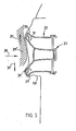
- the horizontal sections 23-25 also crush and provide increased energy absorption, as shown by Fig. 5 .
- the combination of these forces 31 and 31' "throw" the impacted human 29 upward in a direction off the bumper beam 21.
- a majority of the force 31 is upward due to a majority of the person's weight being above the person's knees.
- there is a component of downward vertical forces 31' as shown in Fig. 5 .
- a length of the energy-absorbing stroke of the bumper system 20 ( Fig. 6 ) is extended by use of the beam 21, which has a shallow cross section that takes up less space due to its small depth.
- the beam 21 has a height-to-depth ratio of at least about 3:1, and more preferably of at least about 4:1 or greater, such that the beam 21 flexes and deforms more readily than many existing bumper beams.
- a shallowness of the beam reduces the amount of space taken up by the beam 21 in front of the radiator of the vehicle, and also the combination of the energy absorber 22 and the dynamics of the energy absorption upon impact and crush cause the beam 21 to flex to "catch" a person with a hammock-like action, thus providing reduced injury to pedestrians upon impact.
- the energy absorption is not decreased an unacceptable amount for many vehicles.
- the beam 21 can be bent with a "hammock-like action"
- the beam 21 has considerable strength, such that it flexes and deforms only upon substantial impact and forces being generated. Further, these functional characteristics can be varied by design of the bumper system 20, as discussed below.
- the energy absorber 22 also has end sections 34 ( Fig. 8 ) that extend around ends of the bumper beam 21, forming a collapsible corner that, during impact, initially absorbs energy at a relatively low rate from forces of impact 30 such that it basically "catches" an impacted person.
- the end section 34 also torsionally collapses in direction 36 as it absorbs energy along the lines 37, with a rear portion 38 of the energy absorber 22 slidingly engaging a side of the mount 39.
- the energy absorber 22 develops increasing lateral forces that "throw" the person in a direction 39' sideways away from the vehicle during the continuing impact stroke.
- the illustrated beam 21 ( Fig. 3 ) is a roll-formed channel, and includes a transverse cross section defining a back-and-forth snake-like shape. It is contemplated that other channels can be used, such as extruded or stamped channels, or molded channels, and further that different cross-sectional shapes can be used without departing from a scope of the present invention.
- the present cross section includes a center wall 40; opposing transverse flanges 41, 42 that extend forwardly from each edge and define a channel 43; top and bottom walls 44, 45 that extend upwardly and downwardly from flanges 41, 42, respectively; and top and bottom edge flanges 46, 47 that extend rearwardly from top and bottom walls 44, 45, respectively.
- the front face of beam 21 defines a shape adapted to mateably engage a rear surface of the energy absorber 22, with the channel 43 engaging a ridge 63 on the energy absorber 22 to provide an "anchor" for preventing the energy absorber 22 from sliding up over the beam 21 (or down under the energy absorber 22) during a front impact.
- Apertures or detents 48 are formed in the top and bottom edge flanges 46, 47, for receiving protruding hooks 49 on the energy absorber 22 to temporarily hold the energy absorber 22 on the beam 21 during subassembly.
- a fascia 50 is positioned on the bumper system 20, either before or during assembly of the bumper system 20 to a vehicle.
- the top horizontal section 23 of the energy absorber 22 ( Fig. 3 ) includes a top wall 52 and an upper-mid wall 53 connected by an upper-front wall 54.
- the bottom horizontal section 24 includes a bottom wall 55 and a lower-mid wall 56 connected by a lower-front wall 57.
- the mid-horizontal section 25 includes a mid-front wall 58 that connects the upper-mid wall 53 and the lower-mid wall 56.
- the mid-front wall 58 is recessed rearwardly from the front walls 54 and 57 about an inch-and-a-half or two inches, such that the top and bottom nose sections 26 and 27 protrude forwardly of the mid-front wall 58.
- the half of front walls 54 and 57 that are closest to wall 58 are angled inwardly to form an enlarged "mouth" or entrance to the channel 58', as described below.
- the mid-front wall 58 has rectangular apertures formed therein.
- Vertical/fore/aft reinforcing walls 59 extend transversely between the walls 52, 53, 55, 56 at edges of the apertures and form box-like sections with walls 52, 53, 55, 56 that act to stabilize the walls relative to each other.
- the walls 52-59 can be continuous to form a solid grid of honeycomb shapes, or can be discontinuous and/or include apertures.
- the illustrated mid-front wall 58 has rectangular apertures 60 formed therein that are periodically located along the mid-front wall 58.
- the apertures 60 are bounded by walls 53 and 55 on their top and bottom, and are bounded by vertical walls 59 on their side edges, such that walls 53, 55, and 59 form box-shaped sections around each aperture 60.
- a rear wall 61 is formed along a rear of the energy absorber 22.
- the rear wall 61 along with a rear half inch of the walls 53, 54, 55, 56 forms the ridge 63 that mateably engages the channel 43 on the beam 21.
- the rear wall 61 is aligned with each of the apertures 60, so that the molding die for making the energy absorber 22 can be made without pulls and cams and without moving die parts for making blind surfaces.
- the top and bottom front nose portions 26 and 27 extend forward of the mid-front wall 57 and define a horizontal channel 58' therebetween in front of the mid-front wall 57.
- the front nose portions 26 and 27 are configured to provide a first level of energy absorption during an initial impact stroke that collapses one or both of the front nose portions 26 and 27 with a parallelogram-like motion.
- the parallelogram-like motion provides some energy absorption due to the crumpling effect of the parallelogram motion on the reinforcing walls 59 and also due to the bending forces absorbed by walls 53, 54, 56, and 57.
- a focus of the forces is in the parallelogram action of the nose portions 26 and 27 in combination with a columnar strength of the walls 53, 54, 56, 57, which results in a significant percentage of the horizontal forces of initial impact being converted into vertical forces 31.
- a pedestrian's knee 29' enters the channel 58' and strikes nose portions 26 and 27, causing them to deflect vertically ( Fig. 4 ).
- the top, mid and bottom horizontal sections 23-25 provide a higher second level of energy absorption as the energy absorber 22 crushes and collapses against the face of the beam 21.
- Figs. 6-7 illustrate a second way in which the present bumper system provides reduced injury to pedestrians.
- the impact results in sequential deflection distances 70, 71, 72, and 73.
- the nose portions 26 and 27 of the energy absorber 22 initially bend with a parallelogram-type motion, which results in deflection of a front face of the bumper system a rearward distance 70.
- the energy absorber 22 is crushed against a face of the beam 21 an additional distance 71.
- the beam 21 is deformed an additional distance 72 toward a straightened condition between the vehicle mounts 39.
- the last distance 73 represents a distance of deflection as the mounts 39 telescopingly crush/collapse, and as the bumper beam 21 and energy absorber 22 are driven rearwardly toward the vehicle radiator 75.
- the distances 70-73 are represented on the graph of Fig. 7 by line segments 76-79, with energy absorption being represented by the area under the curve formed by the line segments 76-79. It is noted that the energy absorber 22 can be used on a tubular rigid beam 21' that does not tend to bend, but in such event, the bumper system would take up a dimension 74 and also would only collapse a total of distances 70, 71, and 73' (since the beam 21' would not bend straight).
- the energy absorber 22 is adapted for corner impact by incorporating of the end sections 34 ( Fig. 8 ) that extend around ends of the bumper beam 21.
- the end sections 34 form a collapsible corner that, during impact, initially absorbs energy at a relatively low rate from forces of corner impact 35 such that it basically "catches" a knee of an impacted person.
- the end section(s) 34 also torsionally collapse in direction 36 as it absorbs energy along the lines 37, with a rear portion 38 of the energy absorber 22 slidingly engaging a side of the mount 39.
- the energy absorber 22 develops increasing lateral forces in direction 39' that "throw" the person sideways away from the vehicle during the continuing impact stroke.
- the end section 34 of the energy absorber 22 includes an enlarged free end portion 75 and a transition portion 76 connecting the free end portion 75 to an end of the middle or center section 77 of the energy absorber 22.
- the transition portion 76 includes a trapezoidally shaped rearwardly-extending portion 78 that extends rearwardly to a location adjacent an outer side of the mount 39.
- a honeycomb-shaped box section 79 is located outward of the trapezoidally shaped portion 78, and includes a first side connected to the trapezoidally shaped portion 78, and a second side connected to the free end portion 75.
- impact forces from the impacting body 80 are directed along a line of force, such as line of force 35, into the end section 34.
- the forces are transmitted along lines 37 and 82 through the honeycomb-shaped box section 79, and along line 83 in the trapezoidally shaped portion 78.
- the trapezoidally shaped portion 78 engages a side of the mount 39, and slides rearwardly along the mount 39 in direction 83 as the crash progresses.
- the trapezoidally shaped portion 78 and the honeycomb-shaped box section 79 compress in a manner causing the free end portion 75 to rotate rearwardly along the line 36.
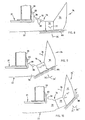
- the honeycomb-shaped box section 79 compresses in a direction 82. Also, the forces associated with the impacting body 80 begin to lessen in the direction of impact (see the shortened arrow 35') and the forces are redirected along the line 39' as the end section 34 resists the corner impact. As the impact continues ( Fig. 10 ), the free end section 75 bends further in direction 36. However, the honeycomb-shaped box section 79 rebounds in a direction 39', adding to the redirected forces 39" and still further reducing the forces 35 ' ' of the impacting body 80 against the end section 34. A result is that the impacting body 80 is "thrown" away from the vehicle by increasing redirected forces 39' and 39' '.
- each of the transition portions 76 initially provide a relatively low-energy absorption and further are torsionally crushed so that the enlarged free end portion 75 swings rearward and "catches" an impacted object such as a human being.
- the transition portions 76 then react during a further continuing part of the bumper stroke, such that the transition portions 76 provide increased energy absorption and counteractive forces such that the free end portion pushes the impacted object away both due to lateral resistive forces developed in the energy absorber non parallel a line of impact and also due to sliding of the impacted object along an inclined surface of the free end portion.
- a bumper system for a vehicle comprises a beam for attachment to a vehicle; an energy absorber engaging a face of the beam; the energy absorber having a top horizontal section defined by a top wall and an upper-mid wall connected by an upper-front wall, and having a bottom horizontal section defined by a bottom wall and a lower-mid wall connected by a lower-front wall, and further having a middle horizontal section defined by a mid-front wall connecting the upper-mid wall and the lower-mid wall, the top and bottom horizontal sections including top and bottom front nose portions that extend forward of the mid-front wall and that define a horizontal channel therebetween in front of the mid-front wall; the front nose portions being configured to provide a first level of energy absorption during an initial impact stroke that collapses at least one of the front nose portions, and the top, middle, and bottom horizontal sections providing a higher second level of energy absorption during a continuing impact stroke that collapses the energy absorber against the face of the beam; and a fascia covering the energy absorber and the beam; whereby, during an
- the top and bottom walls may define wavy and undulating surfaces.
- the beam may have a height-to-depth ratio of at least 3:1.
- the beam may be rollformed.
- the beam face may define a longitudinal forwardly-facing recess
- the energy absorber may include a rearwardly-extending protruding ridge that extends into the forwardly-facing recess.
- the middle horizontal section of the energy absorber may include the rearwardly-extending protruding ridge.
- the top and bottom nose portions may be semi-rigid but collapsible with a parallelogram motion that shifts at least one of the top and bottom front walls vertically, such that horizontal impact forces are converted at least in part to a vertical force upon receiving a horizontal frontal impact.
- the top nose portion may collapse with a parallelogram motion that shifts the upper-front wall upward during an impact.
- a bumper system for a vehicle comprises a beam for attachment to a vehicle and having a longitudinal curvature that, when viewed from above in a vehicle-mounted position, is shaped to match an aerodynamic curvilinear shape of a front of the vehicle; an energy absorber engaging a face of the beam; the energy absorber having a top horizontal section defined by a top wall and an upper-mid wall connected by an upper-front wall, and having a bottom horizontal section defined by a bottom wall and a lower-mid wall connected by a lower-front wall, the top and bottom horizontal sections including top and bottom front nose portions that extend forwardly; the top and bottom nose portions each being semi-rigid but collapsible with a parallelogram motion that shifts at least one of the top and bottom front walls vertically, such that horizontal impact forces are converted at least in part to a vertical force upon receiving a horizontal frontal impact during an initial stroke of the frontal impact; and whereby, during a first part of the frontal impact, the top and bottom front nose portions provide a
- the top and bottom walls may be wavy.
- the beam may have a height-to-depth ratio of at least 3:1.
- the beam may be rollformed.
- the beam face may include a longitudinal forwardly-facing recess, and the energy absorber includes a rearwardly-extending protruding ridge that extends into the forwardly-facing recess.
- the mid-horizontal section of the energy absorber may include the rearwardly-extending protruding ridge.
- a bumper system for a vehicle comprises a beam for attachment to a vehicle and having a curvilinear longitudinal shape when viewed from above in a vehicle-mounted position, the beam including mounts positioned at ends of the beam; an energy absorber engaging a face of the beam; the energy absorber having a middle section engaging the face and further having end sections that extend outwardly from the middle section and at least partially around the associated ends of the beam, the end sections each having an enlarged free end portion and a transition portion connecting the free end portion to an end of the middle section; and each of the transition portions of the end sections of the energy absorber, during a first part of a bumper stroke caused by a corner impact, being constructed to provide a relatively low-energy absorption and further being torsionally crushed so that the enlarged free end portion swings rearward and contacts an impacted object, and then during a further continuing part of the bumper stroke, the transition portion providing increased energy absorption and counteractive forces such that the free end portion pushes the impacted object away both due to lateral
- the beam may include vehicle mounts, and the transition section may include a rear wall that engages and slides on a side of one of the mounts during an impact.
- the free end portion may include a box-shaped middle section that compresses during the first part of the bumper stroke, and that decompresses during the continuing part of the bumper stroke.
- the beam may comprise an open channel.
- the energy absorber may include a honeycomb-shaped middle section that engages the face of the beam.
- a method of reducing pedestrian injury comprises the steps of constructing a bumper system including a stiff beam, and an energy absorber on a face of the beam, the energy absorber having top, middle, and bottom sections, with the top and bottom sections defining nose portions that extend forward of the middle section, the nose sections defining a space therebetween in front of the middle section, the top and bottom nose sections being constructed to deflect with a parallelogram motion upon impact; and shifting at least one of the nose portions vertically with a parallelogram motion in response to an impact directed horizontally against a front of the bumper system, whereby energy directed against a knee of an impacted person is converted into a throwing force that directs the person in a direction generally perpendicular to the line of impact and away from the vehicle bumper system.
- An alternative aspect of the invention consists of a bumper system (20) for a vehicle comprising:
- the beam includes vehicle mounts (39), and the transition section (76) includes a rear wall (78) that engages and slides on a side of one of the mounts during an impact.
- the free end portion (75) includes a box-shaped middle section (79) that compresses during the first part of the bumper stroke, and that decompresses during the continuing part of the bumper stroke.
- the beam (21) comprises an open channel.
- the energy absorber (22) includes a honeycomb-shaped middle section that engages the face of the beam (21).
- An alternative aspect of the invention consists of a method of reducing pedestrian injury comprising steps of:
- An alternative aspect of the invention consists of a bumper system (20) for a vehicle comprising:
- the upper (52,56) and lower walls (53,55) each have a fore-to-aft horizontal length that is substantially longer than a height of the main front wall and angled front wall (54,57), thus assisting in the parallelogram motion.
- the at least one section includes at least an upper horizontal section (23) and a lower horizontal section (24), each having a set of walls including the main front, angled front (54,57), upper (52,56) and lower walls (53,55).
- the bumper system may include stabilizing walls (59) that extend between the lower wall (53) of the upper horizontal section (23) and the upper wall (56) of the lower horizontal section (24), and wherein the upper and lower horizontal sections extend forward of the stabilizing walls to form upper and lower nose portions (26,27), respectively, with a forwardly facing channel (43) therebetween.
- the bumper system may include a fascia (50) extending over and covering the beam (21) and the energy absorber (22), the fascia including a section of material that extends between the upper and lower nose portions (26,27) across the channel (43), the fascia cooperating with the nose portions during a front impact to facilitate and help cause the parallelogram motion.
Landscapes
- Engineering & Computer Science (AREA)
- Mechanical Engineering (AREA)
- Vibration Dampers (AREA)
- Body Structure For Vehicles (AREA)
- Golf Clubs (AREA)
- Pharmaceuticals Containing Other Organic And Inorganic Compounds (AREA)
- Medicines Containing Material From Animals Or Micro-Organisms (AREA)
- Ultra Sonic Daignosis Equipment (AREA)
- Seats For Vehicles (AREA)
Applications Claiming Priority (3)
| Application Number | Priority Date | Filing Date | Title |
|---|---|---|---|
| US10/208,300 US6685243B1 (en) | 2002-07-30 | 2002-07-30 | Bumper for reducing pedestrian injury |
| EP03736473A EP1545937B1 (de) | 2002-07-30 | 2003-04-23 | Stossfänger zur verringerung der verletzung von fussgängern |
| EP09010371A EP2159111B1 (de) | 2002-07-30 | 2003-04-23 | Stossfänger zur Verringerung der Verletzungen von Fussgängern |
Related Parent Applications (2)
| Application Number | Title | Priority Date | Filing Date |
|---|---|---|---|
| EP03736473.4 Division | 2003-04-23 | ||
| EP09010371.4 Division | 2009-08-12 |
Publications (2)
| Publication Number | Publication Date |
|---|---|
| EP2284046A1 true EP2284046A1 (de) | 2011-02-16 |
| EP2284046B1 EP2284046B1 (de) | 2012-12-05 |
Family
ID=30443674
Family Applications (3)
| Application Number | Title | Priority Date | Filing Date |
|---|---|---|---|
| EP09010371A Expired - Lifetime EP2159111B1 (de) | 2002-07-30 | 2003-04-23 | Stossfänger zur Verringerung der Verletzungen von Fussgängern |
| EP03736473A Expired - Lifetime EP1545937B1 (de) | 2002-07-30 | 2003-04-23 | Stossfänger zur verringerung der verletzung von fussgängern |
| EP10012116A Expired - Lifetime EP2284046B1 (de) | 2002-07-30 | 2003-04-23 | Stossfänger zur Verringerung der Verletzungen von Fussgängern |
Family Applications Before (2)
| Application Number | Title | Priority Date | Filing Date |
|---|---|---|---|
| EP09010371A Expired - Lifetime EP2159111B1 (de) | 2002-07-30 | 2003-04-23 | Stossfänger zur Verringerung der Verletzungen von Fussgängern |
| EP03736473A Expired - Lifetime EP1545937B1 (de) | 2002-07-30 | 2003-04-23 | Stossfänger zur verringerung der verletzung von fussgängern |
Country Status (10)
| Country | Link |
|---|---|
| US (3) | US6685243B1 (de) |
| EP (3) | EP2159111B1 (de) |
| JP (1) | JP4488353B2 (de) |
| CN (6) | CN1978251B (de) |
| AT (2) | ATE455679T1 (de) |
| AU (1) | AU2003237087B2 (de) |
| CA (1) | CA2493126A1 (de) |
| DE (1) | DE60331086D1 (de) |
| MX (1) | MXPA05000389A (de) |
| WO (1) | WO2004011306A1 (de) |
Families Citing this family (80)
| Publication number | Priority date | Publication date | Assignee | Title |
|---|---|---|---|---|
| NL1017483C2 (nl) * | 2001-03-02 | 2002-09-03 | Tno | Bumperinrichting. |
| US6672635B2 (en) * | 2002-06-06 | 2004-01-06 | Netshape Corporation | Bumper with integrated foam and non-foam components |
| US6663150B1 (en) * | 2002-06-06 | 2003-12-16 | Netshape Corporation | Bumper with integrated energy absorber and beam |
| EP1378403B1 (de) * | 2002-07-01 | 2005-09-21 | Ford Global Technologies, Inc. | Stossfängeranordnung für Kraftfahrzeug und Verfahren |
| US6923494B2 (en) * | 2002-08-23 | 2005-08-02 | General Electric Company | Pedestrian energy absorber for automotive vehicles |
| US6994384B2 (en) * | 2002-11-20 | 2006-02-07 | General Electric Company | Integrated solitary bumper beam |
| DE10300574A1 (de) * | 2003-01-10 | 2004-07-29 | Daimlerchrysler Ag | Rohkarosserie |
| US20060096099A1 (en) * | 2003-05-08 | 2006-05-11 | Noble Metal Processing, Inc. | Automotive crush tip and method of manufacturing |
| FR2858798B1 (fr) * | 2003-08-11 | 2006-02-03 | Plastic Omnium Cie | Traverse de face avant technique d'un vehicule automobile, face avant technique et support de module de refroidissement munis d'une telle traverse |
| US7017960B2 (en) * | 2003-08-19 | 2006-03-28 | Shape Corporation | Bumper beam having face with supported angled wall |
| US7147258B2 (en) * | 2004-04-13 | 2006-12-12 | Netshape International, Llc | Bumper with nesting energy-absorbing end piece |
| US20050269823A1 (en) * | 2004-06-02 | 2005-12-08 | Shape Corporation | Structural beam incorporating wire reinforcement |
| US7399014B2 (en) * | 2004-07-01 | 2008-07-15 | Magna International Inc. | Bumper system for a motor vehicle |
| JP2006036082A (ja) * | 2004-07-28 | 2006-02-09 | Honda Motor Co Ltd | 車両用バンパー構造 |
| KR100980981B1 (ko) * | 2004-12-01 | 2010-09-07 | 현대자동차주식회사 | 자동차의 충돌 가속도 조절부재 |
| US7163242B2 (en) * | 2005-01-05 | 2007-01-16 | General Electric Company | Bumper system with energy absorber |
| US7367898B2 (en) * | 2005-02-25 | 2008-05-06 | The Aerospace Corporation | Force diversion apparatus and methods and devices including the same |
| US7461726B2 (en) * | 2005-02-25 | 2008-12-09 | The Aerospace Corporation | Force diversion apparatus and methods |
| FR2885095B1 (fr) * | 2005-04-29 | 2009-02-27 | Plastic Omnium Cie | Ensemble d'une peau de pare-chocs et d'un absorbeur en u, absorbeur en u |
| KR100633912B1 (ko) | 2005-09-28 | 2006-10-16 | 현대자동차주식회사 | 차량의 전방 범퍼 보강 구조 |
| JP4171739B2 (ja) * | 2005-10-19 | 2008-10-29 | 小島プレス工業株式会社 | 車両用歩行者保護装置並びにかかる装置における荷重特性のチューニング方法 |
| US7255378B1 (en) * | 2005-10-21 | 2007-08-14 | Ford Global Technologies, Llc | Bumper for automotive vehicle |
| FR2895341B1 (fr) * | 2005-12-23 | 2008-04-04 | Plastic Omnium Cie | Systeme d'absorption d'energie pour un vehicule automobile |
| JP2007204017A (ja) * | 2006-02-06 | 2007-08-16 | Fuji Heavy Ind Ltd | 衝撃吸収部材およびそれを用いた車両用バンパ構造 |
| US8141918B2 (en) * | 2006-02-24 | 2012-03-27 | Honda Motor Co., Ltd. | Pedestrian bumper system and method |
| US7484780B2 (en) * | 2006-04-12 | 2009-02-03 | Chrysler Llc | Bumper beam for automobile |
| FR2904279B1 (fr) * | 2006-07-28 | 2008-11-07 | Renault Sas | Element de pare-choc comportant un element d'absorption de chocs a branches flexibles |
| DE112008000265T5 (de) * | 2007-02-02 | 2010-01-14 | Netshape Energy Management LLC, Novi | Energieabsorber mit Knautschboxen und Hinterriemen |
| JP4330652B2 (ja) | 2007-03-28 | 2009-09-16 | ユニプレス株式会社 | 車両用金属製アブソーバ、車両用バンパシステム、自動車バンパ用アブソーバ及び自動車バンパシステム |
| FR2920723B1 (fr) * | 2007-09-07 | 2010-03-12 | Valeo Systemes Thermiques | Absorbeur de choc pour vehicule automobiles et dispositif comportant un tel absorbeur |
| EP2033855B1 (de) * | 2007-09-10 | 2010-07-28 | Ford Global Technologies, LLC | Fußgängersicherheitseinrichtung für eine Kraftfahrzeugkarosserie |
| US8042847B2 (en) * | 2007-12-19 | 2011-10-25 | Sabic Innovative Plastics Ip B.V. | Tray energy absorber and bumper system |
| US8505990B2 (en) * | 2007-12-21 | 2013-08-13 | Sabic Innovative Plastics Ip B.V. | Corner energy absorber and bumper system |
| US8016331B2 (en) * | 2008-02-14 | 2011-09-13 | Shape Corp. | Energy absorber with sidewall stabilizer ribs |
| US7866716B2 (en) | 2008-04-08 | 2011-01-11 | Flex-N-Gate Corporation | Energy absorber for vehicle |
| DE102008046783B4 (de) * | 2008-09-11 | 2024-03-21 | Volkswagen Ag | Anstoßoptimierter Stoßfänger, insbesondere Frontstoßfänger, an Fahrzeugen |
| US7806448B2 (en) * | 2008-11-04 | 2010-10-05 | Sabic Innovative Plastics Ip B.V. | Vehicle bumper system with energy absorber |
| JP5744041B2 (ja) * | 2009-11-06 | 2015-07-01 | シェイプ・コープShape Corp. | 一様な歩行者への衝撃をもたらすローブを有するエネルギー吸収体 |
| FR2954738B1 (fr) * | 2009-12-24 | 2012-04-06 | Faurecia Bloc Avant | Ensemble pare-chocs pour vehicule automobile, partie d'extremite de vehicule automobile comprenant un tel ensemble et vehicule automobile |
| WO2011109718A2 (en) | 2010-03-05 | 2011-09-09 | Shape Corp. | Hood pedestrian energy absorber |
| US8439411B2 (en) | 2010-04-09 | 2013-05-14 | Magna International Inc. | Bumper beam with integrated energy absorber |
| US20120032458A1 (en) * | 2010-08-04 | 2012-02-09 | Oakwood Energy Management, Inc. | Bumper system with friction-fit energy absorber and method |
| US8684427B2 (en) | 2010-10-29 | 2014-04-01 | Sabic Innovative Plastics Ip B.V. | Reinforced plastic energy absorber system |
| US9302638B2 (en) | 2010-10-29 | 2016-04-05 | Sabic Global Technologies B.V. | Unitary energy absorbing assembly and method of making the same |
| US8336933B2 (en) | 2010-11-04 | 2012-12-25 | Sabic Innovative Plastics Ip B.V. | Energy absorbing device and methods of making and using the same |
| US8322780B2 (en) | 2010-12-20 | 2012-12-04 | Sabic Innovative Plastics Ip B.V. | Reinforced body in white and method of making and using the same |
| US8328251B2 (en) * | 2010-12-17 | 2012-12-11 | Sabic Innovative Plastics Ip B.V. | Asymmetric energy absorber and method of making and using the same |
| US8424629B2 (en) | 2011-03-09 | 2013-04-23 | Shape Corp. | Vehicle energy absorber for pedestrian's upper leg |
| US8454080B2 (en) * | 2011-09-19 | 2013-06-04 | Ford Global Technologies, Llc | Bumper beam with load transferring section |
| US10005408B2 (en) * | 2011-11-03 | 2018-06-26 | Sabic Global Technologies B.V. | Energy absorbing system for conflicting regulatory requirements for vehicle bumpers |
| KR101338076B1 (ko) * | 2011-12-15 | 2013-12-06 | 현대자동차주식회사 | 차량용 범퍼 빔 조립체 |
| US8876179B2 (en) | 2012-02-01 | 2014-11-04 | Sabic Global Technologies B.V. | Energy absorbing assembly and methods of making and using the same |
| US9731669B2 (en) * | 2012-02-28 | 2017-08-15 | Sabic Global Technologies B.V. | Energy absorbing system |
| JP2013189124A (ja) * | 2012-03-14 | 2013-09-26 | Aisin Seiki Co Ltd | 車両用バンパーリインフォースメント |
| US8517454B1 (en) | 2012-06-22 | 2013-08-27 | Nissan North America, Inc. | Vehicle front energy absorber |
| US9194452B2 (en) | 2012-10-31 | 2015-11-24 | The Aerospace Corporation | High stiffness vibration damping apparatus, methods and systems |
| US9067550B2 (en) | 2013-01-18 | 2015-06-30 | Sabic Global Technologies B.V. | Polymer, energy absorber rail extension, methods of making and vehicles using the same |
| US8864216B2 (en) | 2013-01-18 | 2014-10-21 | Sabic Global Technologies B.V. | Reinforced body in white and method of making and using the same |
| US8973957B2 (en) | 2013-04-22 | 2015-03-10 | Shape Corp. | Bumper energy absorber with sensor and configured lobes |
| GB2519810A (en) * | 2013-10-31 | 2015-05-06 | Gm Global Tech Operations Inc | Vehicle front structure |
| JP6131838B2 (ja) * | 2013-11-15 | 2017-05-24 | マツダ株式会社 | 車両の前部構造 |
| CN106458131A (zh) | 2014-06-16 | 2017-02-22 | 沙特基础工业全球技术有限公司 | 制备层压板的方法、吸能装置、吸能装置组合物及成形工具 |
| US9327662B1 (en) * | 2014-11-24 | 2016-05-03 | Toyota Motor Engineering & Manufacturing North America, Inc. | Bumper assemblies including lower reinforcement members |
| US9415734B2 (en) | 2015-01-09 | 2016-08-16 | Toyota Motor Engineering & Manufacturing North America, Inc. | Bumper assemblies for vehicles |
| JP6517558B2 (ja) * | 2015-03-26 | 2019-05-22 | アイシン精機株式会社 | バンパー構造 |
| US9580030B2 (en) | 2015-04-08 | 2017-02-28 | Toyota Motor Engineering & Manufacturing North America, Inc. | Bumper assemblies including lower reinforcement members |
| US9580029B2 (en) | 2015-06-05 | 2017-02-28 | Toyota Motor Engineering & Manufacturing North America, Inc. | Bumper assemblies including a bumper cover reinforcement and vehicles incorporating the same |
| US9669785B2 (en) * | 2015-08-26 | 2017-06-06 | Toyota Motor Engineering & Manufacturing North America, Inc. | Bumper assemblies including spacer members and vehicles incorporating the same |
| US10065587B2 (en) | 2015-11-23 | 2018-09-04 | Flex|N|Gate Corporation | Multi-layer energy absorber |
| USD820749S1 (en) | 2015-12-29 | 2018-06-19 | Sabic Global Technologies B.V. | Roof component for a motor vehicle |
| CN106143396B (zh) * | 2016-07-27 | 2019-05-21 | 浙江吉利控股集团有限公司 | 行人碰撞下肢保护装置、保护方法及汽车 |
| FR3056507A1 (fr) * | 2016-09-29 | 2018-03-30 | Peugeot Citroen Automobiles Sa | Vehicule comprenant un dispositif d’absorption de chocs |
| US10166940B2 (en) * | 2016-11-14 | 2019-01-01 | Ford Global Technologies, Llc | Extendable vehicle grille |
| JP7031356B2 (ja) * | 2018-02-19 | 2022-03-08 | トヨタ自動車株式会社 | 車両前部構造 |
| US10625707B2 (en) | 2018-04-17 | 2020-04-21 | Toyota Motor Engineering & Manufacturing North America, Inc. | Adhesive hood reinforcement for pedestrian protection |
| US11286001B2 (en) | 2019-09-05 | 2022-03-29 | Fca Us Llc | Angled cross member for a vehicle |
| US11052847B2 (en) | 2019-11-18 | 2021-07-06 | GM Global Technology Operations LLC | Impact beam for vehicles |
| CN112124234B (zh) * | 2020-09-09 | 2022-05-17 | 南通通途机电制造有限公司 | 一种新手用停车入库防摩擦磕碰保险杠 |
| US12187328B2 (en) | 2023-08-11 | 2025-01-07 | Southwest Jiaotong University | Guide-type anti-climbing energy-absorbing device based on hydraulic shearing |
| CN116729443B (zh) * | 2023-08-11 | 2023-10-13 | 西南交通大学 | 一种液压剪断导向式防爬吸能装置 |
Citations (3)
| Publication number | Priority date | Publication date | Assignee | Title |
|---|---|---|---|---|
| WO1999056990A1 (en) * | 1998-05-07 | 1999-11-11 | General Electric Company | Vehicle bumper |
| US6406081B1 (en) * | 2001-03-20 | 2002-06-18 | General Electric Company | Energy absorber system |
| EP2116428A1 (de) * | 2001-04-16 | 2009-11-11 | NetShape Energy Management LLC | Stoßfängersystem mit vorderseitenmontiertem Energiedämpfer |
Family Cites Families (30)
| Publication number | Priority date | Publication date | Assignee | Title |
|---|---|---|---|---|
| DE2242666A1 (de) * | 1972-08-30 | 1974-03-21 | Daimler Benz Ag | Stossfaenger fuer kraftfahrzeuge |
| US4050689A (en) * | 1972-12-14 | 1977-09-27 | Ford Motor Company | Pneumatic flexible bumper |
| US4165113A (en) | 1976-01-27 | 1979-08-21 | Paulstra | Multicellular elastomeric shock-absorbing device |
| US4221413A (en) | 1978-02-28 | 1980-09-09 | Yves Bonnetain | Shock absorption bumper for an automotive vehicle |
| FR2445783A1 (fr) * | 1979-01-03 | 1980-08-01 | Peugeot | Dispositif amortisseur de chocs pour face avant de vehicule automobile |
| US4320913A (en) | 1979-10-26 | 1982-03-23 | Shigeharu Kuroda | Shock absorbing bumper for vehicles |
| US4348042A (en) * | 1980-07-14 | 1982-09-07 | Ex-Cell-O Corporation | Vehicle bumper assembly |
| JPS57172848A (en) * | 1981-04-11 | 1982-10-23 | Mazda Motor Corp | Automobile bumper |
| NL8503352A (nl) | 1985-12-05 | 1987-07-01 | Stamicarbon | Bumper. |
| JPS638046A (ja) | 1986-06-27 | 1988-01-13 | Tonen Sekiyukagaku Kk | 自動車用バンパ− |
| US5124186A (en) | 1990-02-05 | 1992-06-23 | Mpa Diversified Products Co. | Composite tubular door beam reinforced with a reacted core localized at the mid-span of the tube |
| US4978562A (en) | 1990-02-05 | 1990-12-18 | Mpa Diversified Products, Inc. | Composite tubular door beam reinforced with a syntactic foam core localized at the mid-span of the tube |
| US5092512A (en) | 1990-03-26 | 1992-03-03 | Shape Corporation | Method of roll-forming an automotive bumper |
| US5005887A (en) | 1990-04-09 | 1991-04-09 | Davidson Textron Inc. | Energy absorbing bumper fastener system |
| JPH04218445A (ja) * | 1990-06-19 | 1992-08-10 | Minoru Sangyo Kk | 合成樹脂製バンパーレインホースメント |
| US5139297A (en) | 1991-09-12 | 1992-08-18 | Ford Motor Company | Internal stroking bumper beam |
| US5290078A (en) * | 1992-06-01 | 1994-03-01 | General Motors Corporation | Integral fasteners for an energy absorber of a vehicular bumper assembly |
| US5219197A (en) | 1992-08-24 | 1993-06-15 | General Motors Corporation | Reinforcing insert for an automotive bumper |
| US5425561A (en) | 1993-12-21 | 1995-06-20 | General Motors Corporation | Flexible insert for an automotive bumper |
| US5545022A (en) | 1994-02-10 | 1996-08-13 | Shape Corporation | Apparatus for manufacturing a vehicle bumper |
| US6165588A (en) | 1998-09-02 | 2000-12-26 | Henkel Corporation | Reinforcement of hollow sections using extrusions and a polymer binding layer |
| US5988713A (en) * | 1996-09-13 | 1999-11-23 | Daikyo Co., Ltd. | Bumper reinforcement |
| US5799991A (en) | 1996-10-23 | 1998-09-01 | Concept Analysis Corporation | Molded bumper system with reinforcement beam |
| DE19804719C1 (de) * | 1998-02-06 | 1999-04-08 | Hummel Anton Verwaltung | Anschlußarmatur mit axial vorstehendem Befestigungsvorsprung |
| US6179355B1 (en) * | 1998-12-18 | 2001-01-30 | Ford Global Technologies, Inc. | Automotive vehicle bumper assembly |
| US6179353B1 (en) * | 1999-07-27 | 2001-01-30 | Shape Corporation | High flex bumper with reinforced corner end sections |
| US6217089B1 (en) | 1999-12-01 | 2001-04-17 | Om Corporation | Bumper reinforcing member |
| JP4368483B2 (ja) | 2000-02-28 | 2009-11-18 | 富士重工業株式会社 | バンパビーム構造 |
| CN2438621Y (zh) * | 2000-09-15 | 2001-07-11 | 高建生 | 汽车吸能缓撞保险杠 |
| US6575510B2 (en) * | 2001-04-16 | 2003-06-10 | Shape Corporation | Bumper system with face-abutting energy absorber |
-
2002
- 2002-07-30 US US10/208,300 patent/US6685243B1/en not_active Expired - Lifetime
-
2003
- 2003-04-23 JP JP2004524478A patent/JP4488353B2/ja not_active Expired - Fee Related
- 2003-04-23 DE DE60331086T patent/DE60331086D1/de not_active Expired - Lifetime
- 2003-04-23 EP EP09010371A patent/EP2159111B1/de not_active Expired - Lifetime
- 2003-04-23 CN CN2006101518988A patent/CN1978251B/zh not_active Expired - Fee Related
- 2003-04-23 WO PCT/US2003/012190 patent/WO2004011306A1/en not_active Ceased
- 2003-04-23 CN CNB200610151894XA patent/CN100450828C/zh not_active Expired - Fee Related
- 2003-04-23 MX MXPA05000389A patent/MXPA05000389A/es active IP Right Grant
- 2003-04-23 CN CNB038176203A patent/CN1325302C/zh not_active Expired - Fee Related
- 2003-04-23 EP EP03736473A patent/EP1545937B1/de not_active Expired - Lifetime
- 2003-04-23 CA CA002493126A patent/CA2493126A1/en not_active Abandoned
- 2003-04-23 AU AU2003237087A patent/AU2003237087B2/en not_active Ceased
- 2003-04-23 AT AT03736473T patent/ATE455679T1/de not_active IP Right Cessation
- 2003-04-23 EP EP10012116A patent/EP2284046B1/de not_active Expired - Lifetime
- 2003-04-23 CN CNB2006101518954A patent/CN100450829C/zh not_active Expired - Fee Related
- 2003-04-23 CN CNA2006101518973A patent/CN1978250A/zh active Pending
- 2003-04-23 AT AT09010371T patent/ATE523385T1/de not_active IP Right Cessation
- 2003-04-23 CN CNA2006101518969A patent/CN1978249A/zh active Pending
- 2003-11-17 US US10/715,002 patent/US7134700B2/en not_active Expired - Lifetime
-
2006
- 2006-07-13 US US11/457,277 patent/US7144054B2/en not_active Expired - Lifetime
Patent Citations (4)
| Publication number | Priority date | Publication date | Assignee | Title |
|---|---|---|---|---|
| WO1999056990A1 (en) * | 1998-05-07 | 1999-11-11 | General Electric Company | Vehicle bumper |
| US6082792A (en) * | 1998-05-07 | 2000-07-04 | General Electric Company | Vehicle bumper |
| US6406081B1 (en) * | 2001-03-20 | 2002-06-18 | General Electric Company | Energy absorber system |
| EP2116428A1 (de) * | 2001-04-16 | 2009-11-11 | NetShape Energy Management LLC | Stoßfängersystem mit vorderseitenmontiertem Energiedämpfer |
Also Published As
Similar Documents
| Publication | Publication Date | Title |
|---|---|---|
| EP1545937B1 (de) | Stossfänger zur verringerung der verletzung von fussgängern | |
| US6926323B2 (en) | Bumper with integrally formed energy absorber | |
| JP2005534555A5 (de) | ||
| US20100066106A1 (en) | Vehicular metal absorber, vehicular bumper system, automobile bumper absorber, and automobile bumper system | |
| EP2116424A1 (de) | Stoßfängersystem mit vorderseitenmontiertem Energiedämpfer | |
| JP2007204017A (ja) | 衝撃吸収部材およびそれを用いた車両用バンパ構造 | |
| JP3185627B2 (ja) | グローブボックス構造 | |
| AU2006202310A1 (en) | Bumper for reducing pedestrian injury | |
| HK1101154A (en) | Bumper for reducing pedestrian injury | |
| HK1100747A (en) | Bumper for reducing pedestrian injury | |
| HK1100864A (en) | Bumper for reducing pedestrian injury | |
| HK1100748A (en) | Bumper for reducing pedestrian injury | |
| HK1100844A (en) | Bumper for reducing pedestrian injury |
Legal Events
| Date | Code | Title | Description |
|---|---|---|---|
| PUAI | Public reference made under article 153(3) epc to a published international application that has entered the european phase |
Free format text: ORIGINAL CODE: 0009012 |
|
| AC | Divisional application: reference to earlier application |
Ref document number: 2159111 Country of ref document: EP Kind code of ref document: P Ref document number: 1545937 Country of ref document: EP Kind code of ref document: P |
|
| AK | Designated contracting states |
Kind code of ref document: A1 Designated state(s): AT BE BG CH CY CZ DE DK EE ES FI FR GB GR HU IE IT LI LU MC NL PT RO SE SI SK TR |
|
| 17P | Request for examination filed |
Effective date: 20110816 |
|
| GRAP | Despatch of communication of intention to grant a patent |
Free format text: ORIGINAL CODE: EPIDOSNIGR1 |
|
| RAP1 | Party data changed (applicant data changed or rights of an application transferred) |
Owner name: SHAPE CORP. |
|
| GRAS | Grant fee paid |
Free format text: ORIGINAL CODE: EPIDOSNIGR3 |
|
| GRAA | (expected) grant |
Free format text: ORIGINAL CODE: 0009210 |
|
| AC | Divisional application: reference to earlier application |
Ref document number: 1545937 Country of ref document: EP Kind code of ref document: P Ref document number: 2159111 Country of ref document: EP Kind code of ref document: P |
|
| AK | Designated contracting states |
Kind code of ref document: B1 Designated state(s): AT BE BG CH CY CZ DE DK EE ES FI FR GB GR HU IE IT LI LU MC NL PT RO SE SI SK TR |
|
| REG | Reference to a national code |
Ref country code: GB Ref legal event code: FG4D |
|
| REG | Reference to a national code |
Ref country code: CH Ref legal event code: EP |
|
| REG | Reference to a national code |
Ref country code: AT Ref legal event code: REF Ref document number: 587085 Country of ref document: AT Kind code of ref document: T Effective date: 20121215 |
|
| REG | Reference to a national code |
Ref country code: IE Ref legal event code: FG4D |
|
| REG | Reference to a national code |
Ref country code: DE Ref legal event code: R096 Ref document number: 60342799 Country of ref document: DE Effective date: 20130131 |
|
| REG | Reference to a national code |
Ref country code: AT Ref legal event code: MK05 Ref document number: 587085 Country of ref document: AT Kind code of ref document: T Effective date: 20121205 |
|
| PG25 | Lapsed in a contracting state [announced via postgrant information from national office to epo] |
Ref country code: FI Free format text: LAPSE BECAUSE OF FAILURE TO SUBMIT A TRANSLATION OF THE DESCRIPTION OR TO PAY THE FEE WITHIN THE PRESCRIBED TIME-LIMIT Effective date: 20121205 Ref country code: ES Free format text: LAPSE BECAUSE OF FAILURE TO SUBMIT A TRANSLATION OF THE DESCRIPTION OR TO PAY THE FEE WITHIN THE PRESCRIBED TIME-LIMIT Effective date: 20130316 Ref country code: SE Free format text: LAPSE BECAUSE OF FAILURE TO SUBMIT A TRANSLATION OF THE DESCRIPTION OR TO PAY THE FEE WITHIN THE PRESCRIBED TIME-LIMIT Effective date: 20121205 |
|
| REG | Reference to a national code |
Ref country code: NL Ref legal event code: VDEP Effective date: 20121205 |
|
| PG25 | Lapsed in a contracting state [announced via postgrant information from national office to epo] |
Ref country code: GR Free format text: LAPSE BECAUSE OF FAILURE TO SUBMIT A TRANSLATION OF THE DESCRIPTION OR TO PAY THE FEE WITHIN THE PRESCRIBED TIME-LIMIT Effective date: 20130306 Ref country code: SI Free format text: LAPSE BECAUSE OF FAILURE TO SUBMIT A TRANSLATION OF THE DESCRIPTION OR TO PAY THE FEE WITHIN THE PRESCRIBED TIME-LIMIT Effective date: 20121205 |
|
| PG25 | Lapsed in a contracting state [announced via postgrant information from national office to epo] |
Ref country code: AT Free format text: LAPSE BECAUSE OF FAILURE TO SUBMIT A TRANSLATION OF THE DESCRIPTION OR TO PAY THE FEE WITHIN THE PRESCRIBED TIME-LIMIT Effective date: 20121205 |
|
| PG25 | Lapsed in a contracting state [announced via postgrant information from national office to epo] |
Ref country code: CZ Free format text: LAPSE BECAUSE OF FAILURE TO SUBMIT A TRANSLATION OF THE DESCRIPTION OR TO PAY THE FEE WITHIN THE PRESCRIBED TIME-LIMIT Effective date: 20121205 Ref country code: SK Free format text: LAPSE BECAUSE OF FAILURE TO SUBMIT A TRANSLATION OF THE DESCRIPTION OR TO PAY THE FEE WITHIN THE PRESCRIBED TIME-LIMIT Effective date: 20121205 Ref country code: BE Free format text: LAPSE BECAUSE OF FAILURE TO SUBMIT A TRANSLATION OF THE DESCRIPTION OR TO PAY THE FEE WITHIN THE PRESCRIBED TIME-LIMIT Effective date: 20121205 Ref country code: BG Free format text: LAPSE BECAUSE OF FAILURE TO SUBMIT A TRANSLATION OF THE DESCRIPTION OR TO PAY THE FEE WITHIN THE PRESCRIBED TIME-LIMIT Effective date: 20130305 Ref country code: EE Free format text: LAPSE BECAUSE OF FAILURE TO SUBMIT A TRANSLATION OF THE DESCRIPTION OR TO PAY THE FEE WITHIN THE PRESCRIBED TIME-LIMIT Effective date: 20121205 |
|
| PG25 | Lapsed in a contracting state [announced via postgrant information from national office to epo] |
Ref country code: PT Free format text: LAPSE BECAUSE OF FAILURE TO SUBMIT A TRANSLATION OF THE DESCRIPTION OR TO PAY THE FEE WITHIN THE PRESCRIBED TIME-LIMIT Effective date: 20130405 Ref country code: RO Free format text: LAPSE BECAUSE OF FAILURE TO SUBMIT A TRANSLATION OF THE DESCRIPTION OR TO PAY THE FEE WITHIN THE PRESCRIBED TIME-LIMIT Effective date: 20121205 Ref country code: NL Free format text: LAPSE BECAUSE OF FAILURE TO SUBMIT A TRANSLATION OF THE DESCRIPTION OR TO PAY THE FEE WITHIN THE PRESCRIBED TIME-LIMIT Effective date: 20121205 |
|
| PLBE | No opposition filed within time limit |
Free format text: ORIGINAL CODE: 0009261 |
|
| STAA | Information on the status of an ep patent application or granted ep patent |
Free format text: STATUS: NO OPPOSITION FILED WITHIN TIME LIMIT |
|
| PG25 | Lapsed in a contracting state [announced via postgrant information from national office to epo] |
Ref country code: DK Free format text: LAPSE BECAUSE OF FAILURE TO SUBMIT A TRANSLATION OF THE DESCRIPTION OR TO PAY THE FEE WITHIN THE PRESCRIBED TIME-LIMIT Effective date: 20121205 |
|
| REG | Reference to a national code |
Ref country code: DE Ref legal event code: R119 Ref document number: 60342799 Country of ref document: DE |
|
| 26N | No opposition filed |
Effective date: 20130906 |
|
| PG25 | Lapsed in a contracting state [announced via postgrant information from national office to epo] |
Ref country code: MC Free format text: LAPSE BECAUSE OF FAILURE TO SUBMIT A TRANSLATION OF THE DESCRIPTION OR TO PAY THE FEE WITHIN THE PRESCRIBED TIME-LIMIT Effective date: 20121205 Ref country code: CY Free format text: LAPSE BECAUSE OF FAILURE TO SUBMIT A TRANSLATION OF THE DESCRIPTION OR TO PAY THE FEE WITHIN THE PRESCRIBED TIME-LIMIT Effective date: 20121205 |
|
| REG | Reference to a national code |
Ref country code: CH Ref legal event code: PL |
|
| GBPC | Gb: european patent ceased through non-payment of renewal fee |
Effective date: 20130423 |
|
| PG25 | Lapsed in a contracting state [announced via postgrant information from national office to epo] |
Ref country code: IT Free format text: LAPSE BECAUSE OF FAILURE TO SUBMIT A TRANSLATION OF THE DESCRIPTION OR TO PAY THE FEE WITHIN THE PRESCRIBED TIME-LIMIT Effective date: 20121205 |
|
| REG | Reference to a national code |
Ref country code: DE Ref legal event code: R097 Ref document number: 60342799 Country of ref document: DE Effective date: 20130906 |
|
| REG | Reference to a national code |
Ref country code: IE Ref legal event code: MM4A |
|
| PG25 | Lapsed in a contracting state [announced via postgrant information from national office to epo] |
Ref country code: LI Free format text: LAPSE BECAUSE OF NON-PAYMENT OF DUE FEES Effective date: 20130430 Ref country code: CH Free format text: LAPSE BECAUSE OF NON-PAYMENT OF DUE FEES Effective date: 20130430 Ref country code: DE Free format text: LAPSE BECAUSE OF NON-PAYMENT OF DUE FEES Effective date: 20131101 Ref country code: GB Free format text: LAPSE BECAUSE OF NON-PAYMENT OF DUE FEES Effective date: 20130423 |
|
| REG | Reference to a national code |
Ref country code: FR Ref legal event code: ST Effective date: 20131231 |
|
| REG | Reference to a national code |
Ref country code: DE Ref legal event code: R119 Ref document number: 60342799 Country of ref document: DE Effective date: 20131101 |
|
| PG25 | Lapsed in a contracting state [announced via postgrant information from national office to epo] |
Ref country code: FR Free format text: LAPSE BECAUSE OF NON-PAYMENT OF DUE FEES Effective date: 20130430 |
|
| PG25 | Lapsed in a contracting state [announced via postgrant information from national office to epo] |
Ref country code: IE Free format text: LAPSE BECAUSE OF NON-PAYMENT OF DUE FEES Effective date: 20130423 |
|
| PG25 | Lapsed in a contracting state [announced via postgrant information from national office to epo] |
Ref country code: TR Free format text: LAPSE BECAUSE OF FAILURE TO SUBMIT A TRANSLATION OF THE DESCRIPTION OR TO PAY THE FEE WITHIN THE PRESCRIBED TIME-LIMIT Effective date: 20121205 |
|
| PG25 | Lapsed in a contracting state [announced via postgrant information from national office to epo] |
Ref country code: LU Free format text: LAPSE BECAUSE OF NON-PAYMENT OF DUE FEES Effective date: 20130423 Ref country code: HU Free format text: LAPSE BECAUSE OF FAILURE TO SUBMIT A TRANSLATION OF THE DESCRIPTION OR TO PAY THE FEE WITHIN THE PRESCRIBED TIME-LIMIT; INVALID AB INITIO Effective date: 20030423 |