EP2284376B1 - Abgasrückführungsvorrichtung für verbrennungsmotor - Google Patents
Abgasrückführungsvorrichtung für verbrennungsmotor Download PDFInfo
- Publication number
- EP2284376B1 EP2284376B1 EP08753117.4A EP08753117A EP2284376B1 EP 2284376 B1 EP2284376 B1 EP 2284376B1 EP 08753117 A EP08753117 A EP 08753117A EP 2284376 B1 EP2284376 B1 EP 2284376B1
- Authority
- EP
- European Patent Office
- Prior art keywords
- pressure egr
- passage
- high pressure
- low pressure
- concentration
- Prior art date
- Legal status (The legal status is an assumption and is not a legal conclusion. Google has not performed a legal analysis and makes no representation as to the accuracy of the status listed.)
- Not-in-force
Links
- 238000002485 combustion reaction Methods 0.000 title claims description 65
- 238000011144 upstream manufacturing Methods 0.000 claims description 36
- 238000001514 detection method Methods 0.000 claims description 13
- 230000001105 regulatory effect Effects 0.000 claims description 11
- 239000000446 fuel Substances 0.000 claims description 5
- 238000002347 injection Methods 0.000 claims description 4
- 239000007924 injection Substances 0.000 claims description 4
- 239000007789 gas Substances 0.000 description 122
- 230000006866 deterioration Effects 0.000 description 18
- 238000000746 purification Methods 0.000 description 12
- 238000010276 construction Methods 0.000 description 7
- 230000001276 controlling effect Effects 0.000 description 7
- 238000000034 method Methods 0.000 description 7
- 239000003054 catalyst Substances 0.000 description 4
- 230000003134 recirculating effect Effects 0.000 description 4
- 238000005259 measurement Methods 0.000 description 3
- 238000006073 displacement reaction Methods 0.000 description 2
- 230000003647 oxidation Effects 0.000 description 2
- 238000007254 oxidation reaction Methods 0.000 description 2
- 239000000498 cooling water Substances 0.000 description 1
- 230000003247 decreasing effect Effects 0.000 description 1
- 238000009429 electrical wiring Methods 0.000 description 1
- 230000007613 environmental effect Effects 0.000 description 1
- 238000002474 experimental method Methods 0.000 description 1
- 230000004043 responsiveness Effects 0.000 description 1
Images


Classifications
-
- F—MECHANICAL ENGINEERING; LIGHTING; HEATING; WEAPONS; BLASTING
- F02—COMBUSTION ENGINES; HOT-GAS OR COMBUSTION-PRODUCT ENGINE PLANTS
- F02D—CONTROLLING COMBUSTION ENGINES
- F02D41/00—Electrical control of supply of combustible mixture or its constituents
- F02D41/02—Circuit arrangements for generating control signals
- F02D41/14—Introducing closed-loop corrections
- F02D41/1438—Introducing closed-loop corrections using means for determining characteristics of the combustion gases; Sensors therefor
- F02D41/1439—Introducing closed-loop corrections using means for determining characteristics of the combustion gases; Sensors therefor characterised by the position of the sensor
- F02D41/144—Sensor in intake manifold
-
- F—MECHANICAL ENGINEERING; LIGHTING; HEATING; WEAPONS; BLASTING
- F02—COMBUSTION ENGINES; HOT-GAS OR COMBUSTION-PRODUCT ENGINE PLANTS
- F02B—INTERNAL-COMBUSTION PISTON ENGINES; COMBUSTION ENGINES IN GENERAL
- F02B37/00—Engines characterised by provision of pumps driven at least for part of the time by exhaust
- F02B37/12—Control of the pumps
- F02B37/16—Control of the pumps by bypassing charging air
- F02B37/162—Control of the pumps by bypassing charging air by bypassing, e.g. partially, intake air from pump inlet to pump outlet
-
- F—MECHANICAL ENGINEERING; LIGHTING; HEATING; WEAPONS; BLASTING
- F02—COMBUSTION ENGINES; HOT-GAS OR COMBUSTION-PRODUCT ENGINE PLANTS
- F02D—CONTROLLING COMBUSTION ENGINES
- F02D41/00—Electrical control of supply of combustible mixture or its constituents
- F02D41/0025—Controlling engines characterised by use of non-liquid fuels, pluralities of fuels, or non-fuel substances added to the combustible mixtures
- F02D41/0047—Controlling exhaust gas recirculation [EGR]
- F02D41/0065—Specific aspects of external EGR control
- F02D41/0072—Estimating, calculating or determining the EGR rate, amount or flow
-
- F—MECHANICAL ENGINEERING; LIGHTING; HEATING; WEAPONS; BLASTING
- F02—COMBUSTION ENGINES; HOT-GAS OR COMBUSTION-PRODUCT ENGINE PLANTS
- F02M—SUPPLYING COMBUSTION ENGINES IN GENERAL WITH COMBUSTIBLE MIXTURES OR CONSTITUENTS THEREOF
- F02M26/00—Engine-pertinent apparatus for adding exhaust gases to combustion-air, main fuel or fuel-air mixture, e.g. by exhaust gas recirculation [EGR] systems
- F02M26/02—EGR systems specially adapted for supercharged engines
- F02M26/04—EGR systems specially adapted for supercharged engines with a single turbocharger
- F02M26/05—High pressure loops, i.e. wherein recirculated exhaust gas is taken out from the exhaust system upstream of the turbine and reintroduced into the intake system downstream of the compressor
-
- F—MECHANICAL ENGINEERING; LIGHTING; HEATING; WEAPONS; BLASTING
- F02—COMBUSTION ENGINES; HOT-GAS OR COMBUSTION-PRODUCT ENGINE PLANTS
- F02M—SUPPLYING COMBUSTION ENGINES IN GENERAL WITH COMBUSTIBLE MIXTURES OR CONSTITUENTS THEREOF
- F02M26/00—Engine-pertinent apparatus for adding exhaust gases to combustion-air, main fuel or fuel-air mixture, e.g. by exhaust gas recirculation [EGR] systems
- F02M26/02—EGR systems specially adapted for supercharged engines
- F02M26/04—EGR systems specially adapted for supercharged engines with a single turbocharger
- F02M26/06—Low pressure loops, i.e. wherein recirculated exhaust gas is taken out from the exhaust downstream of the turbocharger turbine and reintroduced into the intake system upstream of the compressor
-
- F—MECHANICAL ENGINEERING; LIGHTING; HEATING; WEAPONS; BLASTING
- F02—COMBUSTION ENGINES; HOT-GAS OR COMBUSTION-PRODUCT ENGINE PLANTS
- F02M—SUPPLYING COMBUSTION ENGINES IN GENERAL WITH COMBUSTIBLE MIXTURES OR CONSTITUENTS THEREOF
- F02M26/00—Engine-pertinent apparatus for adding exhaust gases to combustion-air, main fuel or fuel-air mixture, e.g. by exhaust gas recirculation [EGR] systems
- F02M26/13—Arrangement or layout of EGR passages, e.g. in relation to specific engine parts or for incorporation of accessories
- F02M26/22—Arrangement or layout of EGR passages, e.g. in relation to specific engine parts or for incorporation of accessories with coolers in the recirculation passage
-
- F—MECHANICAL ENGINEERING; LIGHTING; HEATING; WEAPONS; BLASTING
- F02—COMBUSTION ENGINES; HOT-GAS OR COMBUSTION-PRODUCT ENGINE PLANTS
- F02M—SUPPLYING COMBUSTION ENGINES IN GENERAL WITH COMBUSTIBLE MIXTURES OR CONSTITUENTS THEREOF
- F02M26/00—Engine-pertinent apparatus for adding exhaust gases to combustion-air, main fuel or fuel-air mixture, e.g. by exhaust gas recirculation [EGR] systems
- F02M26/45—Sensors specially adapted for EGR systems
-
- F—MECHANICAL ENGINEERING; LIGHTING; HEATING; WEAPONS; BLASTING
- F02—COMBUSTION ENGINES; HOT-GAS OR COMBUSTION-PRODUCT ENGINE PLANTS
- F02D—CONTROLLING COMBUSTION ENGINES
- F02D41/00—Electrical control of supply of combustible mixture or its constituents
- F02D41/0002—Controlling intake air
- F02D41/0007—Controlling intake air for control of turbo-charged or super-charged engines
-
- Y—GENERAL TAGGING OF NEW TECHNOLOGICAL DEVELOPMENTS; GENERAL TAGGING OF CROSS-SECTIONAL TECHNOLOGIES SPANNING OVER SEVERAL SECTIONS OF THE IPC; TECHNICAL SUBJECTS COVERED BY FORMER USPC CROSS-REFERENCE ART COLLECTIONS [XRACs] AND DIGESTS
- Y02—TECHNOLOGIES OR APPLICATIONS FOR MITIGATION OR ADAPTATION AGAINST CLIMATE CHANGE
- Y02T—CLIMATE CHANGE MITIGATION TECHNOLOGIES RELATED TO TRANSPORTATION
- Y02T10/00—Road transport of goods or passengers
- Y02T10/10—Internal combustion engine [ICE] based vehicles
- Y02T10/12—Improving ICE efficiencies
-
- Y—GENERAL TAGGING OF NEW TECHNOLOGICAL DEVELOPMENTS; GENERAL TAGGING OF CROSS-SECTIONAL TECHNOLOGIES SPANNING OVER SEVERAL SECTIONS OF THE IPC; TECHNICAL SUBJECTS COVERED BY FORMER USPC CROSS-REFERENCE ART COLLECTIONS [XRACs] AND DIGESTS
- Y02—TECHNOLOGIES OR APPLICATIONS FOR MITIGATION OR ADAPTATION AGAINST CLIMATE CHANGE
- Y02T—CLIMATE CHANGE MITIGATION TECHNOLOGIES RELATED TO TRANSPORTATION
- Y02T10/00—Road transport of goods or passengers
- Y02T10/10—Internal combustion engine [ICE] based vehicles
- Y02T10/40—Engine management systems
Definitions
- the present invention relates to an exhaust gas recirculation apparatus for an internal combustion engine.
- US 2007/079614 discloses a system and method for high pressure and low pressure exhaust gas recirculation control and estimation while US 4 168 683 discloses a feedback control system for recirculation of exhaust gas, and US 2006/213490 discloses a system and method for adjusting the exhaust gas recirculation rate in an internal combustion engine.
- the present invention has been made in view of the above-mentioned problems, and has for its object to provide a technique which, in an exhaust gas recirculation apparatus for an internal combustion engine, can calculate a low pressure EGR rate and a high pressure EGR rate in an accurate manner, and control the flow rates of both a low pressure EGR passage and a high pressure EGR passage in a closed-loop control manner, thereby to make the temperature of intake air and a supercharging pressure stable and to suppress the deterioration of exhaust emissions as well as the deterioration of power performance.
- the present invention resides in an exhaust gas recirculation apparatus according to claim 1 for an internal combustion engine which is characterized by comprising:
- the low pressure EGR rate representative of the proportion of an amount of low pressure EGR gas to an amount of intake air sucked into the internal combustion engine and the high pressure EGR rate representative of the proportion of an amount of high pressure EGR gas to said amount of intake air are calculated by using the CO 2 concentration in the intake passage at a location downstream of the connection portion of the low pressure EGR passage and upstream of the connection portion of the high pressure EGR passage, the CO 2 concentration in the intake passage at a location downstream the connection portion of the high pressure EGR passage, and the CO 2 concentration of the exhaust gas discharged from the internal combustion engine.
- the amount of low pressure EGR gas can be calculated in an accurate manner when the low pressure EGR rate is obtained, so it is possible to calculate the flow rate of exhaust gas that passes through an exhaust gas purification device arranged on the exhaust passage in an accurate manner when using both the low pressure EGR passage and the high pressure EGR passage in combination, thus making it possible to improve the accuracy in the temperature control of the exhaust gas purification device.
- the CO 2 concentrations at the respective portions can be detected in an accurate manner, and both of the low pressure EGR rate and the high pressure EGR rate can be calculated in an accurate manner by the use of the CO 2 concentrations at the respective portions.
- the CO 2 concentrations at the respective portions can be derived in an accurate manner while making cost reduction by using only the single expensive CO 2 concentration detector, and both of the low pressure EGR rate and the high pressure EGR rate can be calculated in an accurate manner by the use of the CO 2 concentrations at the respective portions.
- the CO 2 concentration of mixed gases after the fresh air and the low pressure EGR gas have been mixed with each other to a satisfactory extent to become the constant pressure is detected, so the mixed gases are uniformly mixed with each other to be at the constant pressure, as a result of which it is possible to reduce measurement errors at the time of detection, and to detect the CO 2 concentration of the mixed gases in an accurate manner.
- the low pressure EGR rate and the high pressure EGR rate can be calculated in an accurate manner, and the flow rates of both a low pressure EGR passage and a high pressure EGR passage can be controlled in a closed-loop control manner, whereby the intake air temperature and the supercharging pressure can be stabilized, thus making it possible to suppress the deterioration of exhaust emissions and the deterioration of power performance.
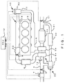
- Fig. 1 shows the schematic construction of an internal combustion engine with its intake and exhaust systems to which an exhaust gas recirculation apparatus for an internal combustion engine is applied.
- the internal combustion engine 1 as shown in Fig. 1 is a water-cooled four-stroke cycle diesel engine having four cylinders 2.
- An intake passage 3 and an exhaust passage 4 are connected with the internal combustion engine 1.
- An intercooler 8 for performing heat exchange between intake air and outside air is arranged on the intake passage 3 at a location downstream of the compressor housing 5a. Also, a second throttle valve 9 for adjusting the flow rate of intake air passing through the intake passage 3 is arranged on the intake passage 3 at a location downstream of the intercooler 8. The second throttle valve 9 is opened and closed by means of an electric actuator.
- a turbine housing 5b of the turbocharger 5 is arranged on an intermediate portion of the exhaust passage 4 connected with the internal combustion engine 1.
- an exhaust gas purification device 10 is arranged on the exhaust passage 4 at a downstream side of the turbine housing 5b.
- the exhaust gas purification device 10 is constructed to have an oxidation catalyst, and a particulate filter (hereinafter simply referred to as a filter) that is arranged at the following stage (downstream side) of the oxidation catalyst.
- a particulate filter hereinafter simply referred to as a filter
- An occlusion reduction type NOx catalyst hereinafter referred to simply as a NOx catalyst
- An exhaust gas throttle valve 11 for adjusting the flow rate of the exhaust gas passing through the exhaust passage 4 is arranged on the exhaust passage 4 at a location downstream of the exhaust gas purification device 10.
- the exhaust gas throttle valve 11 is opened and closed by means of an electric actuator.
- a low pressure EGR device 30 for returning (recirculating) a part of the exhaust gas passing through the exhaust passage 4 to the intake passage 3 at low pressure is mounted on the internal combustion engine 1.
- the low pressure EGR device 30 is constructed to include a low pressure EGR passage 31, a low pressure EGR valve (LPL valve) 32, and a low pressure EGR cooler 33.
- LPL valve low pressure EGR valve
- the low pressure EGR passage 31 serves to connect between a portion of the exhaust passage 4 which is downstream of the exhaust gas purification device 10 and upstream of the exhaust gas throttle valve 11, and a portion of the intake passage 3 which is upstream of the compressor housing 5a and downstream of the first throttle valve 6.
- the exhaust gas is sent to the internal combustion engine 1 through the low pressure EGR passage 31 at low pressure.
- the exhaust gas recirculating through the low pressure EGR passage 31 is called a low pressure EGR gas (LPL gas).
- the low pressure EGR valve 32 serves to control the amount of the low pressure EGR gas flowing through the low pressure EGR passage 31 by adjusting the passage cross sectional area of the low pressure EGR passage 31.
- the adjustment of the amount of low pressure EGR gas can be performed by means of methods other than adjusting the degree of opening of the low pressure EGR valve 32. For example, by adjusting the degree of opening of the first throttle valve 6, a differential pressure between the upstream and downstream sides of the low pressure EGR passage 31 is changed, whereby the amount of the low pressure EGR gas can be adjusted.
- the low pressure EGR cooler 33 lowers the temperature of the low pressure EGR gas by performing heat exchange between the low pressure EGR gas passing through the low pressure EGR cooler 33 and the cooling water in the internal combustion engine 1.
- a high pressure EGR device 40 for returning or recirculating a part of the exhaust gas passing through the exhaust passage 4 to the intake passage 3 at high pressure is mounted on the internal combustion engine 1.
- the high pressure EGR device 40 is constructed to include a high pressure EGR passage 41 and a high pressure EGR valve (HPL valve) 42.
- the high pressure EGR passage 41 serves to connect between a portion of the exhaust passage 4 which is upstream of the turbine housing 5b and a portion of the intake passage 3 which is downstream of the compressor housing 5a.
- the exhaust gas is sent to the internal combustion engine 1 at high pressure through the high pressure EGR passage 41.
- the exhaust gas recirculating through the high pressure EGR passage 41 is called a high pressure EGR gas (HPL gas).
- the high pressure EGR valve 42 serves to control the amount of the high pressure EGR gas flowing through the high pressure EGR passage 41 by adjusting the passage cross sectional area of the high pressure EGR passage 41.
- the adjustment of the amount of high pressure EGR gas can be performed by means of methods other than adjusting the degree of opening of the high pressure EGR valve 42.
- the degree of opening of the second throttle valve 9 a differential pressure between the upstream and downstream sides of the high pressure EGR passage 41 is changed, whereby the amount of the high pressure EGR gas can be adjusted.
- the turbocharger 5 is of a variable volume type
- the amount of the high pressure EGR gas can be controlled by adjusting the degree of opening of a nozzle vane that changes the flow characteristic of the turbine.
- An ECU 12 in the form of an electronic control unit for controlling the internal combustion engine 1 is provided in conjunction with the internal combustion engine 1 as constructed in the above-described manner.
- This ECU 12 serves to control the operating state of the internal combustion engine 1 in accordance with the operating condition of the internal combustion engine 1 and driver's requirements.
- a variety of kinds of sensors such as the air flow meter 7, etc., are connected to the ECU 12 through electric wiring, so that the output signals of the various sensors are input to the ECU 12.
- the individual actuators for the first throttle valve 6, the second throttle valve 9, the exhaust gas throttle valve 11, the low pressure EGR valve 32 and the high pressure EGR valve 42 are also connected to the ECU 12 through electrical wiring, so that these valves are controlled by means of the ECU 12.
- the low pressure EGR rate which represents the proportion of the low pressure EGR gas to the intake air sucked to the internal combustion engine 1
- the high pressure EGR rate which represents the proportion of the high pressure EGR gas to the intake sucked to the internal combustion engine 1
- the flow control of both the low pressure EGR passage 31 and the high pressure EGR passage 41 is carried out in a closed-loop control manner by calculating the low pressure EGR rate and the high pressure EGR rate in an accurate manner, and by controlling these low and high pressure EGR rates to the individual target values.
- the intake air temperature and the supercharging pressure can be stabilized, whereby the deterioration of exhaust emissions can be suppressed, and the deterioration of power performance can be suppressed.
- the amount of low pressure EGR gas can be calculated in an accurate manner when the low pressure EGR rate is obtained, so it is possible to calculate the flow rate of the exhaust gas passing through the exhaust gas purification apparatus 10 arranged on the exhaust passage 4 in an accurate manner when using both the low pressure EGR passage 31 and the high pressure EGR passage 41 in combination, thereby making it possible to improve the accuracy in the temperature control of the exhaust gas purification device 10.
- the low pressure EGR rate and the high pressure EGR rate in this embodiment is calculated by using the CO 2 concentrations at three locations, i.e., the CO 2 concentration in the intake passage 3 at a location downstream of the connection portion of the low pressure EGR passage 31 and upstream of the connection portion of the high pressure EGR passage, the CO 2 concentration in the intake passage 3 at a downstream side of the connection portion of the high pressure EGR passage 41, and the CO 2 concentration of the exhaust gas discharged from the internal combustion engine 1.
- the CO 2 concentrations at the three locations are detected by means of O 2 concentration sensors 13, 14, 15, respectively. That is, in this embodiment, there are provided the O 2 concentration sensor 13 for detecting the CO 2 concentration in the intake passage 3 at a location downstream of the connection portion of the low pressure EGR passage 31 and upstream of the connection portion of the high pressure EGR passage, the O 2 concentration sensor 14 for detecting the CO 2 concentration in the intake passage 3 at a location downstream of the connection portion of the high pressure EGR passage 41, and the O 2 concentration sensor 15 for detecting the CO 2 concentration of the exhaust gas discharged from the internal combustion engine1. With such an arrangement, the CO 2 concentrations at the respective locations or portions can be detected in an accurate manner, and both of the low pressure EGR rate and the high pressure EGR rate can be calculated in an accurate manner by the use of the CO 2 concentrations at the respective locations or portions.
- the reason for detecting the CO 2 concentrations by means of the O 2 concentration sensors 13, 14, 15 is that an O 2 concentration and a CO 2 concentration are in a one-to-one relation and hence the CO 2 concentration can be replaced by the O 2 concentration. Therefore, the O 2 concentration sensors 13, 14, 15 in this embodiment correspond to the first through third CO 2 concentration detection units, respectively, of the present invention.
- the O 2 concentrations are a measured so as to detect the CO 2 concentrations, but besides this, the CO 2 concentrations may instead be detected by measuring H 2 O concentrations, N 2 concentrations.
- the CO 2 concentration of the fresh air is CO2N (CO2N is the CO 2 concentration of the atmosphere and hence is known);
- CO2N is the CO 2 concentration of the atmosphere and hence is known;
- the CO 2 concentration of a mixed gas of the fresh air and the low pressure EGR gas detected by the O 2 concentration sensor 13 is CO2NL;
- the CO 2 concentration of a mixed gas of the fresh air, the low pressure EGR gas and the high pressure EGR gas detected by the O 2 concentration sensor 14 is CO2NLH;
- the CO 2 concentration of the exhaust gas detected by the O 2 concentration sensor 15 is CO2EH.
- Ghpl CO 2 EH ⁇ CO 2 N / CO 2 EH ⁇ CO 2 NLH ⁇ CO 2 NL ⁇ CO 2 N / CO 2 EH ⁇ CO 2 NL ⁇ 1 ⁇ Gn
- the low pressure EGR rate can be calculated from equations (1), (2) and (4) above, and the high pressure EGR rate can be calculated from equations (1), (3) and (5) above.
- the low pressure EGR valve 32 and the high pressure EGR valve 42 By controlling the low pressure EGR valve 32 and the high pressure EGR valve 42, the low pressure EGR rate and the high pressure EGR rate to be calculated are controlled to the individual target values, respectively.
- target values of the low pressure EGR rate and the high pressure EGR rate are values which are appropriately set in accordance with the operating state of the internal combustion engine 1 and surrounding environmental conditions.
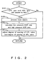
- FIG. 2 is a flow chart illustrating the routine for EGR rate control according to this embodiment. This routine is repeatedly carried out at every predetermined time interval.
- step S101 the ECU 12 determines whether the low pressure EGR gas and the high pressure EGR gas are caused to flow.
- a determination as to whether the low pressure EGR gas and the high pressure EGR gas are caused to flow is made by the opened/ closed states of the low pressure EGR valve 32 and the high-pressure EGR valve 42, of which the degree of opening of the low pressure EGR valve 32 and the degree of opening of the high pressure EGR valve 42 are detected by means of unillustrated opening sensors, respectively.
- step S101 when the low pressure EGR valve 32 and/or the high pressure EGR valve 42 are/is in a closed state(s) with a determination made that the low pressure EGR gas and the high pressure EGR gas are not caused to pass through, the ECU 12 once terminates this routine.
- the control flow proceeds to step S102.
- step S102 the ECU 11 processes the input signals from the air flow meter 7, the O 2 concentration sensors 13, 14, 15, etc.
- step S103 the ECU 11 calculates the low pressure EGR rate and the high pressure EGR rate.
- the low pressure EGR rate is calculated from the above-mentioned equations (1), (2) and (4)
- the high pressure EGR rate is calculated from the above-mentioned equations (1), (3) and (5), by using the amount of fresh air Gn measured by the air flow meter 7 and the CO 2 concentration measured by the O 2 concentration sensors 13, 14, 15.
- the ECU 12 calculating the low pressure EGR rate and the high pressure EGR rate in this step corresponds to a calculation unit of the present invention.
- step S104 the ECU 12 adjusts the degree of opening of the low pressure EGR valve 32 and the degree of opening of the high pressure EGR valve 42 so as to control the low pressure EGR rate and the high pressure EGR rate to be calculated in step S103 to the individual target values, respectively.
- the degree of opening of the low pressure EGR valve 32 is adjusted in accordance with the difference of the low pressure EGR rate and its target value, and at the same time, the degree of opening of the high pressure EGR valve 42 is also adjusted in accordance with the difference of the high pressure EGR rate and its target value.
- the amounts of adjustment for the degrees of opening of the low pressure EGR valve 32 and the high pressure EGR valve 42 can be acquired by applying the differences between the low pressure EGR rate and the high pressure EGR rate and their target values, respectively, to a map.
- the map representing the correlation between the degrees of the opening and the differences is obtained beforehand through experiments, etc., and is stored in the ECU 12.
- the ECU 12 which controls the low pressure EGR rate and the high pressure EGR rate to the individual target values by adjusting the degree of opening of the low pressure EGR valve 32 and the degree of opening of the high pressure EGR valve 42, corresponds to an EGR rate control unit of the present invention.
- the flow control of both the low pressure EGR passage and the high pressure EGR passage is carried out in a closed-loop control manner by calculating the low pressure EGR rate and the high pressure EGR rate in an accurate manner, and by controlling these low and high pressure EGR rates to the individual target values.
- the control of the low pressure EGR rate and the high pressure EGR rate has been performed only by adjusting the degree of opening of the low pressure EGR valve 32 and the degree of opening of the high pressure EGR valve 42.
- the present invention is not limited to this, and the low pressure EGR rate and the high pressure EGR rate can be controlled by adjusting the degree of opening of the low pressure EGR valve 32 and the degree of opening of the high pressure EGR valve 42 in addition to adjusting the degree of opening of the first and second throttle valves 6, 9 and the degree of opening of the nozzle vane of the variable capacity type turbocharger.
- the CO 2 concentrations at the three locations or portions have been measured by the individual O 2 concentration sensors, respectively.
- the O 2 concentration sensors are expensive, and hence arranging the three sensors for one internal combustion engine results in an increase in cost.
- this embodiment is provided with only a single CO 2 concentration sensor 13 for detecting a CO 2 concentration in an intake passage at a location downstream of a connection portion of a low pressure EGR passage 31 and upstream of a connection portion of a high pressure EGR passage 41, and CO 2 concentrations at the other locations are obtained by arithmetic calculation.
- the construction other than the above is similar to the above-mentioned embodiment, so overlapping explanations are omitted.
- Fig. 3 shows the schematic construction of an internal combustion engine with an intake system and an exhaust system to which an exhaust gas recirculation apparatus for an internal combustion engine according to this embodiment is applied.
- An intake pressure sensor 16 for detecting the intake pressure in the intake passage 3 at a downstream side of the connection portion of the high pressure EGR passage 41 is arranged on the intake passage 3 at a downstream side of the connection portion of the high pressure EGR passage 41.
- an intake air temperature sensor 17 for detecting an intake air temperature in the intake passage 3 at a downstream side of the connection portion of the high pressure EGR passage 41 is arranged on the intake passage 3 at a downstream side of the connection portion of the high pressure EGR passage 41.
- the flow control of both the low pressure EGR passage and the high pressure EGR passage is carried out in a closed-loop control manner by calculating the low pressure EGR rate and the high pressure EGR rate in an accurate manner, and by controlling these low and high pressure EGR rates to the individual target values.
- the intake air temperature and the supercharging pressure can be stabilized, whereby the deterioration of exhaust emissions can be suppressed, and the deterioration of power performance can be suppressed.
- the amount of low pressure EGR gas can be calculated in an accurate manner when the low pressure EGR rate is obtained, so it is possible to calculate the flow rate of the exhaust gas passing through the exhaust gas purification apparatus 10 arranged on the exhaust passage 4 in an accurate manner when using both the low pressure EGR passage 31 and the high pressure EGR passage 41 in combination, thereby making it possible to improve the accuracy in the temperature control of the exhaust gas purification device 10.
- the low pressure EGR rate and the high pressure EGR rate in this embodiment is calculated by using the CO 2 concentrations at three locations, i.e., the CO 2 concentration in the intake passage 3 at a location downstream of the connection portion of the low pressure EGR passage 31 and upstream of the connection portion of the high pressure EGR passage, the CO 2 concentration in the intake passage 3 at a downstream side of the connection portion of the high pressure EGR passage 41, and the CO 2 concentration of the exhaust gas discharged from the internal combustion engine 1.
- the CO 2 concentration at one of the above-mentioned three locations is detected by the O 2 concentration sensor 13, and the CO 2 concentrations at the other two locations are obtained by arithmetic calculation. That is, this embodiment is provided with the O 2 concentration sensor 13 for detecting the CO 2 concentration in the intake passage 3 at the location downstream of the connection portion of the low pressure EGR passage 31 and upstream of the connection portion of the high pressure EGR passage 41.
- the O 2 concentration sensor 13 in this embodiment corresponds to a first CO 2 concentration detection unit of the present invention.
- the CO 2 concentration in the intake passage 3 at the downstream side of the connection portion of the high pressure EGR passage 41 and the CO 2 concentration of the exhaust gas discharged from the internal combustion engine 1 are calculated by arithmetic calculation.
- Gcyl Pim ⁇ Vcyl ⁇ ⁇ v / R ⁇ Tim
- Pim the intake pressure (measure by the intake pressure sensor 16)
- Vcyl is the cylinder volume, cylinder capacity or volumetric displacement, ⁇ v is the volumetric efficiency, R is the gas constant, and Tim is the intake air temperature (measured by the intake air temperature sensor 17).
- CO 2 concentration CO2EH of the exhaust gas which is the CO 2 concentration discharged from the internal combustion engine 1
- Gn the amount of fresh air (measured by the air flow meter 7)
- Q is the amount of injection fuel (the amount of fuel to be injected by the internal combustion engine 1, which is an amount instructed by the ECU 12).
- equation (8) above is a predetermined function which derives the CO 2 concentration CO2EH of the exhaust gas from the values of Gn, Q.
- the CO 2 concentration in the intake passage 3 at a downstream side of the connection portion of the high pressure EGR passage 41 can be derived from equations (6), (7) and (8), and the concentration of CO 2 discharged from the internal combustion engine 1 can be derived from equation (8).
- the ECU 12, which derives, from equations (6), (7) and (8) of this embodiment, the CO 2 concentration in the intake passage 3 at the downstream side of the connection portion of the high pressure EGR passage 41 corresponds to a first CO 2 concentration calculation unit of the present invention.
- the ECU 12, which derives the concentration of CO 2 discharged from the internal combustion engine 1 from equation (8) of this second embodiment corresponds to a second CO 2 concentration calculation unit of the present invention.
- the CO 2 concentrations at the respective three locations required to be obtained can be derived in an accurate manner while making cost reduction by using only the single expensive CO 2 concentration sensor, and both of the low pressure EGR rate and the high pressure EGR rate can be calculated in an accurate manner by the use of the CO 2 concentrations at the respective locations.
- the O 2 concentration sensor 13 which detects the CO 2 concentration in the intake passage 3 at a location downstream of the connection portion of the low pressure EGR passage 31 and upstream of the connection portion of the high pressure EGR passage 41, is arranged in the intake passage 3 at a location upstream of the compressor housing 5a.
- the intake passage 3 at the upstream side of the compressor housing 5a in which the O 2 concentration sensor 13 is arranged fresh air and a low pressure EGR gas are not mixed with each other to a satisfactory extent, and hence, it has been impossible to detect an accurate CO 2 concentration.
- a bypass passage 18 which serves to return intake air in a first portion of the intake passage 3 at the downstream side of the compressor housing 5a to a second portion of the intake passage 3 at the upstream side of the compressor housing 5a, and the concentration of CO 2 in the bypass passage 18 is detected by the O 2 concentration sensor 13.
- a pressure regulating valve 19 for regulating the pressure in the bypass passage 18 at a downstream side thereof to a constant level is arranged in the bypass passage 18 so that fresh air and the low pressure EGR gas flowing in the bypass passage 18 in the bypass passage 18 can be mixed with each other to a satisfactory extent to become a substantially constant pressure, thereby making it possible to decrease a measurement error of the O 2 concentration sensor 13.
- Fig. 4 shows the schematic construction of an internal combustion engine with an intake system and an exhaust system to which the exhaust gas recirculation apparatus for an internal combustion engine according to this embodiment of the present invention is applied.
- the bypass passage 18 which serves to return intake air in the first portion of the intake passage 3 at the downstream side of the compressor housing 5a to the second portion of the intake passage 3 at the upstream side of the compressor housing 5a.
- the pressure regulating valve 19 for regulating the pressure in the bypass passage 18 at the downstream side thereof to the constant level is provided in the bypass passage 18.
- the pressure regulating valve 19 in this third embodiment corresponds to a pressure regulating unit of the present invention.
- the O 2 concentration sensor 13 for detecting the CO 2 concentration in the intake passage 3 at the location downstream of the connection portion of the low pressure EGR passage 31 and upstream of the connection portion of the high pressure EGR passage 41.
- the O 2 concentration sensor 13 in this embodiment corresponds to the first CO 2 concentration detection unit of the present invention.
- the CO 2 concentration of mixed gases after the fresh air and the low pressure EGR gas have been mixed with each other to a satisfactory extent to become the constant pressure is detected, so the mixed gases are uniformly mixed with each other to be at the constant pressure, as a result of which measurement errors at the time of detection can be reduced, thereby making it possible to detect the CO 2 concentration of the mixed gases having the fresh air and the low pressure EGR gas mixed with each other in an accurate manner.
- the flow control of both the low pressure EGR passage and the high pressure EGR passage is carried out in a closed-loop control manner by calculating both of the low pressure EGR rate and the high pressure EGR rate in an accurate manner, and by controlling these low and high pressure EGR rates to the individual target values.
- the intake air temperature and the supercharging pressure can be stabilized, whereby the deterioration of exhaust emissions can be suppressed, and the deterioration of power performance can be suppressed.
- the amount of low pressure EGR gas can be calculated in an accurate manner when the low pressure EGR rate is obtained, so it is possible to calculate the flow rate of the exhaust gas passing through the exhaust gas purification apparatus 10 that is arranged on the exhaust passage 4 in an accurate manner when using both the low pressure EGR passage 31 and the high pressure EGR passage 41 in combination, thereby making it possible to improve the accuracy in the temperature control of the exhaust gas purification device 10.
- An exhaust gas recirculation apparatus for an internal combustion engine according to the present invention is not limited to the above-mentioned embodiments, but various changes may be made therein within the range not departing from the scope of the present invention as defined in the appended claims.
- a low-pressure EGR rate and a high-pressure EGR rate can be calculated in an accurate manner, and the flow rates of both a low pressure EGR passage and a high pressure EGR passage can be controlled in a closed-loop control manner, whereby the intake air temperature and the supercharging pressure can be stabilized, thus making it possible to suppress the deterioration of exhaust emissions and the deterioration of power performance.
Landscapes
- Engineering & Computer Science (AREA)
- Chemical & Material Sciences (AREA)
- Combustion & Propulsion (AREA)
- Mechanical Engineering (AREA)
- General Engineering & Computer Science (AREA)
- Analytical Chemistry (AREA)
- Exhaust-Gas Circulating Devices (AREA)
- Output Control And Ontrol Of Special Type Engine (AREA)
Claims (3)
- Abgasrückführungsvorrichtung für einen Verbrennungsmotor (1), umfassend:einen Turbolader (5), der eine Turbine (5b), die an einem Auslasskanal (4) des Verbrennungsmotors angeordnet ist, und einen Verdichter (5a), der an einem Einlasskanal (3) des Verbrennungsmotors angeordnet ist, aufweist,einen Niederdruck-AGR-Kanal (31), der dazu dient, einen Teil eines Abgases aus dem Auslasskanal (4) an einer Position stromabwärts der Turbine als Niederdruck-AGR-Gas aufzunehmen und das Niederdruck-AGR-Gas an einer Position stromaufwärts des Verdichters zu dem Einlasskanal (3) zurückzuführen,einen Hochdruck-AGR-Kanal (41), der dazu dient, einen Teil des Abgases aus dem Auslasskanal (4) an einer Position stromaufwärts der Turbine als Hochdruck-AGR-Gas aufzunehmen und das Hochdruck-AGR-Gas an einer Position stromabwärts des Verdichters zu dem Einlasskanal (3) zurückzuführen,eine Berechnungseinheit (12), die eine Niederdruck-AGR-Rate, welche für das Verhältnis einer Menge von Niederdruck-AGR-Gas zu einer Menge von Ansaugluft, die in den Verbrennungsmotor (1) gesaugt wird, repräsentativ ist, und eine Hochdruck-AGR-Rate, die für das Verhältnis einer Menge von Hochdruck-AGR-Gas zu der Menge von Ansaugluft repräsentativ ist, mittels einer CO2-Konzentration in dem Einlasskanal (3) an einer Position stromabwärts eines Verbindungsabschnitts des Niederdruck-AGR-Kanals (31) und stromaufwärts eines Verbindungsabschnitts des Hochdruck-AGR-Kanals, einer CO2-Konzentration in dem Einlasskanal (3) an einer Position stromabwärts des Verbindungsabschnitts des Hochdruck-AGR-Kanals (41) und einer CO2-Konzentration des von dem Verbrennungsmotor (1) abgegebenen Abgases berechnet,eine AGR-Ratenregeleinheit (12), welche die Niederdruck-AGR-Rate bzw. die Hochdruck-AGR-Rate, welche durch die Berechnungseinheit berechnet werden, auf individuelle Sollwerte regelt,dadurch gekennzeichnet, dass sie ferner umfasst:einen Bypass-Kanal (18), der, in dem Einlasskanal (3) an einer Position stromabwärts des Verbindungsabschnitts des Niederdruck-AGR-Kanals (31) und stromaufwärts des Verbindungsabschnitts des Hochdruck-AGR-Kanals (41), die Ansaugluft in dem Einlasskanal (3) an einer Position stromabwärts des Verdichters an einer Position stromaufwärts des Verdichters (5a) zu dem Einlasskanal zurückführt,eine Druckregeleinheit, die den Druck in dem Bypass-Kanal (18) an einer stromabwärtigen Seite davon auf einen konstanten Pegel regelt, undeine erste CO2-Konzentrationsdetektiereinheit (13), die in dem Bypass-Kanal (18) stromabwärts der Druckregeleinheit die CO2-Konzentration in dem Einlasskanal (3) an einer Position stromabwärts des Verbindungsabschnitts des Niederdruck-AGR-Kanals (31) und stromaufwärts des Verbindungsabschnitts des Hochdruck-AGR-Kanals (41) detektiert.
- Abgasrückführungsvorrichtung für einen Verbrennungsmotor nach Anspruch 1, dadurch gekennzeichnet, dass diese umfasst:eine zweite CO2-Konzentrationsdetektiereinheit (14), welche die CO2-Konzentration in dem Einlasskanal (3) an einer Position stromabwärts des Verbindungsabschnitts des Hochdruck-AGR-Kanals (41) detektiert, undeine dritte CO2-Konzentrationsdetektiereinheit (15), welche die CO2-Konzentration des von dem Verbrennungsmotor abgegebenen Abgases detektiert.
- Abgasrückführungsvorrichtung für einen Verbrennungsmotor nach Anspruch 1, dadurch gekennzeichnet, dass diese umfasst:eine zweite CO2-Konzentrationsberechnungseinheit (12), welche die CO2-Konzentration des von dem Verbrennungsmotor (1) abgegebenen Abgases aus der Frischluftmenge und der Kraftstoffeinspritzmenge berechnet.
Applications Claiming Priority (1)
| Application Number | Priority Date | Filing Date | Title |
|---|---|---|---|
| PCT/JP2008/059610 WO2009141917A1 (ja) | 2008-05-20 | 2008-05-20 | 内燃機関の排気還流装置 |
Publications (3)
| Publication Number | Publication Date |
|---|---|
| EP2284376A1 EP2284376A1 (de) | 2011-02-16 |
| EP2284376A4 EP2284376A4 (de) | 2015-07-08 |
| EP2284376B1 true EP2284376B1 (de) | 2016-08-24 |
Family
ID=41339866
Family Applications (1)
| Application Number | Title | Priority Date | Filing Date |
|---|---|---|---|
| EP08753117.4A Not-in-force EP2284376B1 (de) | 2008-05-20 | 2008-05-20 | Abgasrückführungsvorrichtung für verbrennungsmotor |
Country Status (4)
| Country | Link |
|---|---|
| US (1) | US8108129B2 (de) |
| EP (1) | EP2284376B1 (de) |
| CN (1) | CN101688483B (de) |
| WO (1) | WO2009141917A1 (de) |
Families Citing this family (32)
| Publication number | Priority date | Publication date | Assignee | Title |
|---|---|---|---|---|
| US8630787B2 (en) * | 2005-12-20 | 2014-01-14 | Borgwarner Inc. | Controlling exhaust gas recirculation in a turbocharged engine system |
| EP2474731B1 (de) * | 2009-09-03 | 2020-08-19 | Toyota Jidosha Kabushiki Kaisha | Abgasrückführungsvorrichtung für einen verbrennungsmotor |
| US8707935B2 (en) | 2009-10-28 | 2014-04-29 | Ford Global Technologies, Llc | Exhaust gas recirculation system with a NOx sensor |
| WO2011087661A2 (en) * | 2009-12-22 | 2011-07-21 | Borgwarner Inc. | Internal combustion engine |
| JP5056953B2 (ja) * | 2010-03-09 | 2012-10-24 | トヨタ自動車株式会社 | 内燃機関の制御装置 |
| US9181904B2 (en) | 2010-08-10 | 2015-11-10 | Ford Global Technologies, Llc | Method and system for exhaust gas recirculation control |
| DE102011002553A1 (de) | 2011-01-12 | 2012-07-12 | Ford Global Technologies, Llc | Aufgeladene Brennkraftmaschine und Verfahren zum Betreiben einer derartigen Brennkraftmaschine |
| DE112011104862T5 (de) * | 2011-02-09 | 2013-11-07 | Honda Motor Co., Ltd. | Abgasreinigungssystem für einen Verbrennungsmotor |
| US9267449B2 (en) | 2011-06-16 | 2016-02-23 | GM Global Technology Operations LLC | Control system and method for coordinating throttle and boost |
| US20140219826A1 (en) * | 2011-08-15 | 2014-08-07 | Eaton Corporation | Fuel system using dual pressure hi-speed centrifugal pump arrangement |
| US9157390B2 (en) | 2011-09-21 | 2015-10-13 | GM Global Technology Operations LLC | Selective exhaust gas recirculation diagnostic systems and methods |
| KR101316863B1 (ko) * | 2011-12-09 | 2013-10-08 | 기아자동차주식회사 | 배기가스 재순환 진단 방법 및 시스템 |
| EP2623755A3 (de) * | 2012-01-31 | 2017-04-19 | International Engine Intellectual Property Company, LLC | Änderung eines Sauerstoffkonzentrationseinstellwerts |
| US10066564B2 (en) | 2012-06-07 | 2018-09-04 | GM Global Technology Operations LLC | Humidity determination and compensation systems and methods using an intake oxygen sensor |
| US9249764B2 (en) | 2012-03-06 | 2016-02-02 | GM Global Technology Operations LLC | Engine control systems and methods with humidity sensors |
| CN102607658B (zh) * | 2012-03-08 | 2013-09-18 | 北京航空航天大学 | 一种基于浓度法的复杂结构通道内气体流量测量方法 |
| US9932917B2 (en) | 2012-03-21 | 2018-04-03 | GM Global Technology Operations LLC | Exhaust gas recirculation control systems and methods |
| US20130268176A1 (en) * | 2012-04-05 | 2013-10-10 | GM Global Technology Operations LLC | Exhaust gas recirculation control systems and methods for low engine delta pressure conditions |
| US9341133B2 (en) | 2013-03-06 | 2016-05-17 | GM Global Technology Operations LLC | Exhaust gas recirculation control systems and methods |
| US9541039B2 (en) * | 2013-03-14 | 2017-01-10 | Cummins Ip, Inc. | Apparatus, system, and method for reducing emission of nitrogen oxides |
| US9726091B2 (en) * | 2013-03-15 | 2017-08-08 | Cummins Inc. | Active control of one or more EGR loops |
| WO2014205168A1 (en) * | 2013-06-21 | 2014-12-24 | Eaton Corporation | Supercharger exhaust bypass |
| US9631567B2 (en) | 2013-08-15 | 2017-04-25 | GM Global Technology Operations LLC | Sensor based measurement and purge control of fuel vapors in internal combustion engines |
| US9309838B2 (en) | 2013-08-20 | 2016-04-12 | Ford Global Technologies, Llc | Methods and systems for indicating water at an oxygen sensor based on sensor heater power consumption |
| WO2015131183A2 (en) | 2014-02-28 | 2015-09-03 | Cummins Inc. | System, method, and apparatus for managing aftertreatment component efficiency during motoring |
| JP6098835B2 (ja) * | 2014-09-25 | 2017-03-22 | マツダ株式会社 | エンジンの排気制御装置 |
| EP3040541B1 (de) * | 2014-12-09 | 2025-06-04 | Marelli Europe S.p.A. | Verfahren zur bestimmung des massedurchflusses eines niederdruck-abgasrückführungskreislaufs eines aufgeladenen verbrennungsmotors |
| JP6327199B2 (ja) * | 2015-05-07 | 2018-05-23 | 株式会社デンソー | 内燃機関の低水温冷却装置 |
| CN106609713A (zh) * | 2015-10-19 | 2017-05-03 | 北汽福田汽车股份有限公司 | 降低废气中的nox的方法和装置及排气再循环系统 |
| DE102018200369B4 (de) | 2018-01-11 | 2020-07-16 | Ford Global Technologies, Llc | Echtzeit-Steuerung eines Abgasrückführungssystems |
| US11225921B2 (en) * | 2020-05-29 | 2022-01-18 | Woodward, Inc. | Engine exhaust treatment through temperature management |
| CN114562371B (zh) * | 2020-11-27 | 2023-04-28 | 长城汽车股份有限公司 | 车辆的最优废气再循环率的确定方法、装置、存储介质及车辆 |
Family Cites Families (18)
| Publication number | Priority date | Publication date | Assignee | Title |
|---|---|---|---|---|
| JPS5855345B2 (ja) * | 1976-11-30 | 1983-12-09 | 日産自動車株式会社 | 排気還流制御装置 |
| US4942860A (en) * | 1987-02-06 | 1990-07-24 | Toyota Jidosha Kabushiki Kaisha | Engine control system |
| JPH01155051A (ja) | 1987-12-11 | 1989-06-16 | Mazda Motor Corp | ディーゼルエンジンの燃料制御装置 |
| JPH0518324A (ja) | 1991-07-12 | 1993-01-26 | Mitsubishi Electric Corp | 機関の排気ガス再循環制御装置 |
| JP3038512B2 (ja) | 1991-09-10 | 2000-05-08 | ヤンマーディーゼル株式会社 | ディーゼル機関の排気ガス還流装置 |
| JP3518203B2 (ja) * | 1996-11-14 | 2004-04-12 | トヨタ自動車株式会社 | Egr装置付き内燃機関 |
| US6301888B1 (en) * | 1999-07-22 | 2001-10-16 | The United States Of America As Represented By The Administrator Of The Environmental Protection Agency | Low emission, diesel-cycle engine |
| JP4000987B2 (ja) | 2002-10-29 | 2007-10-31 | 三菱ふそうトラック・バス株式会社 | 圧縮着火式内燃機関 |
| US6948475B1 (en) * | 2002-11-12 | 2005-09-27 | Clean Air Power, Inc. | Optimized combustion control of an internal combustion engine equipped with exhaust gas recirculation |
| DE602004012986T2 (de) * | 2004-06-15 | 2009-06-04 | C.R.F. Società Consortile per Azioni, Orbassano | Verfahren und Einrichtung zur Bestimmung der Ansaugluftmenge einer Brennkraftmaschine basierend auf der Messung der Sauerstoffkonzentration in einem der Brennkraftmaschine zugeführten Gasgemisch |
| DE102005013977B4 (de) * | 2005-03-26 | 2020-09-03 | Ford Global Technologies, Llc | Abgasrückführsystem für ein Kraftfahrzeug und Verfahren zum Einstellen der Abgasrückführrate in einem Gasrückführsystem |
| JP2006322363A (ja) | 2005-05-18 | 2006-11-30 | Mazda Motor Corp | エンジンの内部egr率推定方法 |
| JP2006336547A (ja) | 2005-06-02 | 2006-12-14 | Hino Motors Ltd | Egr装置 |
| US7380400B2 (en) * | 2005-10-06 | 2008-06-03 | Ford Global Technologies, Llc | System and method for high pressure and low pressure exhaust gas recirculation control and estimation |
| DE102005044266A1 (de) * | 2005-09-16 | 2007-03-29 | Robert Bosch Gmbh | Verfahren zum Betreiben einer Brennkraftmaschine und Brennkraftmaschine |
| JP2007321658A (ja) | 2006-06-01 | 2007-12-13 | Toyota Motor Corp | 内燃機関の排気還流装置 |
| JP4218702B2 (ja) | 2006-06-22 | 2009-02-04 | トヨタ自動車株式会社 | 内燃機関の排気還流装置 |
| JP4285528B2 (ja) * | 2006-11-06 | 2009-06-24 | トヨタ自動車株式会社 | 内燃機関の排気再循環システム |
-
2008
- 2008-05-20 CN CN2008800011348A patent/CN101688483B/zh not_active Expired - Fee Related
- 2008-05-20 WO PCT/JP2008/059610 patent/WO2009141917A1/ja not_active Ceased
- 2008-05-20 US US12/445,558 patent/US8108129B2/en not_active Expired - Fee Related
- 2008-05-20 EP EP08753117.4A patent/EP2284376B1/de not_active Not-in-force
Also Published As
| Publication number | Publication date |
|---|---|
| CN101688483B (zh) | 2012-04-18 |
| WO2009141917A1 (ja) | 2009-11-26 |
| EP2284376A4 (de) | 2015-07-08 |
| EP2284376A1 (de) | 2011-02-16 |
| CN101688483A (zh) | 2010-03-31 |
| US8108129B2 (en) | 2012-01-31 |
| US20110054762A1 (en) | 2011-03-03 |
Similar Documents
| Publication | Publication Date | Title |
|---|---|---|
| EP2284376B1 (de) | Abgasrückführungsvorrichtung für verbrennungsmotor | |
| JP4715799B2 (ja) | 内燃機関の排気還流装置 | |
| EP2198141B1 (de) | Abgasrückführungsvorrichtung und verfahren zur kalkulation der abgasrückführungsflussrate für einen verbrennungsmotor | |
| EP1870584B1 (de) | Abgasrückführvorrichtung für einen Verbrennungsmotor und Steuerungsverfahren für die Vorrichtung | |
| EP2530262B1 (de) | STEUERGERÄT FÜR VERBRENNUNGSMOTOR UND VORRICHTUNG ZUM MESSEN DES MASSENSTROMS VON ZURÜCKSCHWAPPENDEM NOx ZUR AUFNAHME ZUSAMMEN MIT EINEM DURCHBLASGAS | |
| EP2292917B1 (de) | AGR-Strömungsratensteuerungsvorrichtung eines Verbrennungsmotors | |
| EP1963646B1 (de) | Steuerung der abgasrückführung in einem turbolader-motorsystem | |
| EP1607606B1 (de) | Verfahren und Einrichtung zur Bestimmung der Ansaugluftmenge einer Brennkraftmaschine basierend auf der Messung der Sauerstoff-Konzentration in einem der Brennkraftmaschine zugeführten Gasgemisch | |
| US6321732B1 (en) | Air flow and EGR flow estimation | |
| US8700291B2 (en) | System for controlling the exhaust gas return rate by means of virtual NOx sensors with adaptation via a NOx sensor | |
| US6055810A (en) | Feedback control of direct injected engines by use of a smoke sensor | |
| EP1996803B1 (de) | Abgasreinigungsvorrichtung für verbrennungsmotor und steuerverfahren dafür | |
| US8346462B2 (en) | Malfunction detection apparatus and malfunction detection method for an EGR system | |
| EP3179087B1 (de) | Fehlerbestimmungseinheit | |
| EP2392802A2 (de) | Steuerung der Abgasrückführung einer Brennkraftmaschine mit Turbolader | |
| US6981492B2 (en) | Method for determining an exhaust gas recirculation amount | |
| EP3029307B1 (de) | Steuerungsvorrichtung für verbrennungsmotor | |
| US8751137B2 (en) | Apparatus for estimating exhaust gas recirculation quantity | |
| JP2005264805A (ja) | 内燃機関の制御装置 | |
| JP2020041435A (ja) | 排気再循環装置の動作制御方法及び排気再循環装置 | |
| JP2007303380A (ja) | 内燃機関の排気制御装置 | |
| EP2418371B1 (de) | Agr-steuersystem für einen verbrennungsmotor | |
| EP1482153B1 (de) | Brennkraftmaschine und Verfahren zur Steuerung des Ladeluftmassenstroms und der Abgasrückführungsrate | |
| JP4910844B2 (ja) | 内燃機関の排気浄化装置 | |
| CN116202775A (zh) | 一种发动机缸内气量预估方法及系统 |
Legal Events
| Date | Code | Title | Description |
|---|---|---|---|
| PUAI | Public reference made under article 153(3) epc to a published international application that has entered the european phase |
Free format text: ORIGINAL CODE: 0009012 |
|
| 17P | Request for examination filed |
Effective date: 20090505 |
|
| AK | Designated contracting states |
Kind code of ref document: A1 Designated state(s): AT BE BG CH CY CZ DE DK EE ES FI FR GB GR HR HU IE IS IT LI LT LU LV MC MT NL NO PL PT RO SE SI SK TR |
|
| AX | Request for extension of the european patent |
Extension state: AL BA MK RS |
|
| DAX | Request for extension of the european patent (deleted) | ||
| RAP1 | Party data changed (applicant data changed or rights of an application transferred) |
Owner name: TOYOTA JIDOSHA KABUSHIKI KAISHA |
|
| RA4 | Supplementary search report drawn up and despatched (corrected) |
Effective date: 20150609 |
|
| RIC1 | Information provided on ipc code assigned before grant |
Ipc: F02M 25/07 20060101ALI20150716BHEP Ipc: F02D 21/08 20060101AFI20150716BHEP Ipc: F02D 23/00 20060101ALI20150716BHEP Ipc: F02D 41/00 20060101ALI20150716BHEP |
|
| RIC1 | Information provided on ipc code assigned before grant |
Ipc: F02M 26/05 20160101ALI20160122BHEP Ipc: F02D 23/00 20060101ALI20160122BHEP Ipc: F02D 41/14 20060101ALI20160122BHEP Ipc: F02M 26/06 20160101ALI20160122BHEP Ipc: F02D 21/08 20060101AFI20160122BHEP Ipc: F02D 41/00 20060101ALI20160122BHEP Ipc: F02B 37/16 20060101ALI20160122BHEP |
|
| GRAP | Despatch of communication of intention to grant a patent |
Free format text: ORIGINAL CODE: EPIDOSNIGR1 |
|
| INTG | Intention to grant announced |
Effective date: 20160315 |
|
| GRAS | Grant fee paid |
Free format text: ORIGINAL CODE: EPIDOSNIGR3 |
|
| GRAA | (expected) grant |
Free format text: ORIGINAL CODE: 0009210 |
|
| AK | Designated contracting states |
Kind code of ref document: B1 Designated state(s): AT BE BG CH CY CZ DE DK EE ES FI FR GB GR HR HU IE IS IT LI LT LU LV MC MT NL NO PL PT RO SE SI SK TR |
|
| REG | Reference to a national code |
Ref country code: GB Ref legal event code: FG4D |
|
| REG | Reference to a national code |
Ref country code: CH Ref legal event code: EP |
|
| REG | Reference to a national code |
Ref country code: AT Ref legal event code: REF Ref document number: 823327 Country of ref document: AT Kind code of ref document: T Effective date: 20160915 |
|
| REG | Reference to a national code |
Ref country code: IE Ref legal event code: FG4D |
|
| REG | Reference to a national code |
Ref country code: DE Ref legal event code: R096 Ref document number: 602008045873 Country of ref document: DE |
|
| REG | Reference to a national code |
Ref country code: LT Ref legal event code: MG4D |
|
| REG | Reference to a national code |
Ref country code: NL Ref legal event code: MP Effective date: 20160824 |
|
| REG | Reference to a national code |
Ref country code: AT Ref legal event code: MK05 Ref document number: 823327 Country of ref document: AT Kind code of ref document: T Effective date: 20160824 |
|
| PG25 | Lapsed in a contracting state [announced via postgrant information from national office to epo] |
Ref country code: NL Free format text: LAPSE BECAUSE OF FAILURE TO SUBMIT A TRANSLATION OF THE DESCRIPTION OR TO PAY THE FEE WITHIN THE PRESCRIBED TIME-LIMIT Effective date: 20160824 Ref country code: NO Free format text: LAPSE BECAUSE OF FAILURE TO SUBMIT A TRANSLATION OF THE DESCRIPTION OR TO PAY THE FEE WITHIN THE PRESCRIBED TIME-LIMIT Effective date: 20161124 Ref country code: LT Free format text: LAPSE BECAUSE OF FAILURE TO SUBMIT A TRANSLATION OF THE DESCRIPTION OR TO PAY THE FEE WITHIN THE PRESCRIBED TIME-LIMIT Effective date: 20160824 Ref country code: IT Free format text: LAPSE BECAUSE OF FAILURE TO SUBMIT A TRANSLATION OF THE DESCRIPTION OR TO PAY THE FEE WITHIN THE PRESCRIBED TIME-LIMIT Effective date: 20160824 Ref country code: FI Free format text: LAPSE BECAUSE OF FAILURE TO SUBMIT A TRANSLATION OF THE DESCRIPTION OR TO PAY THE FEE WITHIN THE PRESCRIBED TIME-LIMIT Effective date: 20160824 Ref country code: HR Free format text: LAPSE BECAUSE OF FAILURE TO SUBMIT A TRANSLATION OF THE DESCRIPTION OR TO PAY THE FEE WITHIN THE PRESCRIBED TIME-LIMIT Effective date: 20160824 |
|
| REG | Reference to a national code |
Ref country code: DE Ref legal event code: R084 Ref document number: 602008045873 Country of ref document: DE |
|
| PG25 | Lapsed in a contracting state [announced via postgrant information from national office to epo] |
Ref country code: AT Free format text: LAPSE BECAUSE OF FAILURE TO SUBMIT A TRANSLATION OF THE DESCRIPTION OR TO PAY THE FEE WITHIN THE PRESCRIBED TIME-LIMIT Effective date: 20160824 Ref country code: LV Free format text: LAPSE BECAUSE OF FAILURE TO SUBMIT A TRANSLATION OF THE DESCRIPTION OR TO PAY THE FEE WITHIN THE PRESCRIBED TIME-LIMIT Effective date: 20160824 Ref country code: GR Free format text: LAPSE BECAUSE OF FAILURE TO SUBMIT A TRANSLATION OF THE DESCRIPTION OR TO PAY THE FEE WITHIN THE PRESCRIBED TIME-LIMIT Effective date: 20161125 Ref country code: PT Free format text: LAPSE BECAUSE OF FAILURE TO SUBMIT A TRANSLATION OF THE DESCRIPTION OR TO PAY THE FEE WITHIN THE PRESCRIBED TIME-LIMIT Effective date: 20161226 Ref country code: ES Free format text: LAPSE BECAUSE OF FAILURE TO SUBMIT A TRANSLATION OF THE DESCRIPTION OR TO PAY THE FEE WITHIN THE PRESCRIBED TIME-LIMIT Effective date: 20160824 Ref country code: SE Free format text: LAPSE BECAUSE OF FAILURE TO SUBMIT A TRANSLATION OF THE DESCRIPTION OR TO PAY THE FEE WITHIN THE PRESCRIBED TIME-LIMIT Effective date: 20160824 |
|
| REG | Reference to a national code |
Ref country code: FR Ref legal event code: PLFP Year of fee payment: 10 |
|
| PG25 | Lapsed in a contracting state [announced via postgrant information from national office to epo] |
Ref country code: RO Free format text: LAPSE BECAUSE OF FAILURE TO SUBMIT A TRANSLATION OF THE DESCRIPTION OR TO PAY THE FEE WITHIN THE PRESCRIBED TIME-LIMIT Effective date: 20160824 Ref country code: EE Free format text: LAPSE BECAUSE OF FAILURE TO SUBMIT A TRANSLATION OF THE DESCRIPTION OR TO PAY THE FEE WITHIN THE PRESCRIBED TIME-LIMIT Effective date: 20160824 |
|
| REG | Reference to a national code |
Ref country code: DE Ref legal event code: R097 Ref document number: 602008045873 Country of ref document: DE |
|
| PG25 | Lapsed in a contracting state [announced via postgrant information from national office to epo] |
Ref country code: PL Free format text: LAPSE BECAUSE OF FAILURE TO SUBMIT A TRANSLATION OF THE DESCRIPTION OR TO PAY THE FEE WITHIN THE PRESCRIBED TIME-LIMIT Effective date: 20160824 Ref country code: SK Free format text: LAPSE BECAUSE OF FAILURE TO SUBMIT A TRANSLATION OF THE DESCRIPTION OR TO PAY THE FEE WITHIN THE PRESCRIBED TIME-LIMIT Effective date: 20160824 Ref country code: CZ Free format text: LAPSE BECAUSE OF FAILURE TO SUBMIT A TRANSLATION OF THE DESCRIPTION OR TO PAY THE FEE WITHIN THE PRESCRIBED TIME-LIMIT Effective date: 20160824 Ref country code: DK Free format text: LAPSE BECAUSE OF FAILURE TO SUBMIT A TRANSLATION OF THE DESCRIPTION OR TO PAY THE FEE WITHIN THE PRESCRIBED TIME-LIMIT Effective date: 20160824 Ref country code: BG Free format text: LAPSE BECAUSE OF FAILURE TO SUBMIT A TRANSLATION OF THE DESCRIPTION OR TO PAY THE FEE WITHIN THE PRESCRIBED TIME-LIMIT Effective date: 20161124 Ref country code: BE Free format text: LAPSE BECAUSE OF FAILURE TO SUBMIT A TRANSLATION OF THE DESCRIPTION OR TO PAY THE FEE WITHIN THE PRESCRIBED TIME-LIMIT Effective date: 20160824 |
|
| PLBE | No opposition filed within time limit |
Free format text: ORIGINAL CODE: 0009261 |
|
| STAA | Information on the status of an ep patent application or granted ep patent |
Free format text: STATUS: NO OPPOSITION FILED WITHIN TIME LIMIT |
|
| 26N | No opposition filed |
Effective date: 20170526 |
|
| PG25 | Lapsed in a contracting state [announced via postgrant information from national office to epo] |
Ref country code: SI Free format text: LAPSE BECAUSE OF FAILURE TO SUBMIT A TRANSLATION OF THE DESCRIPTION OR TO PAY THE FEE WITHIN THE PRESCRIBED TIME-LIMIT Effective date: 20160824 Ref country code: LU Free format text: LAPSE BECAUSE OF NON-PAYMENT OF DUE FEES Effective date: 20170531 |
|
| REG | Reference to a national code |
Ref country code: CH Ref legal event code: PL |
|
| GBPC | Gb: european patent ceased through non-payment of renewal fee |
Effective date: 20170520 |
|
| PG25 | Lapsed in a contracting state [announced via postgrant information from national office to epo] |
Ref country code: MC Free format text: LAPSE BECAUSE OF FAILURE TO SUBMIT A TRANSLATION OF THE DESCRIPTION OR TO PAY THE FEE WITHIN THE PRESCRIBED TIME-LIMIT Effective date: 20160824 |
|
| REG | Reference to a national code |
Ref country code: IE Ref legal event code: MM4A |
|
| PG25 | Lapsed in a contracting state [announced via postgrant information from national office to epo] |
Ref country code: LI Free format text: LAPSE BECAUSE OF NON-PAYMENT OF DUE FEES Effective date: 20170531 Ref country code: CH Free format text: LAPSE BECAUSE OF NON-PAYMENT OF DUE FEES Effective date: 20170531 |
|
| PG25 | Lapsed in a contracting state [announced via postgrant information from national office to epo] |
Ref country code: LU Free format text: LAPSE BECAUSE OF NON-PAYMENT OF DUE FEES Effective date: 20170520 |
|
| REG | Reference to a national code |
Ref country code: FR Ref legal event code: PLFP Year of fee payment: 11 |
|
| PG25 | Lapsed in a contracting state [announced via postgrant information from national office to epo] |
Ref country code: GB Free format text: LAPSE BECAUSE OF NON-PAYMENT OF DUE FEES Effective date: 20170520 Ref country code: IE Free format text: LAPSE BECAUSE OF NON-PAYMENT OF DUE FEES Effective date: 20170520 |
|
| PG25 | Lapsed in a contracting state [announced via postgrant information from national office to epo] |
Ref country code: MT Free format text: LAPSE BECAUSE OF NON-PAYMENT OF DUE FEES Effective date: 20170520 |
|
| PG25 | Lapsed in a contracting state [announced via postgrant information from national office to epo] |
Ref country code: HU Free format text: LAPSE BECAUSE OF FAILURE TO SUBMIT A TRANSLATION OF THE DESCRIPTION OR TO PAY THE FEE WITHIN THE PRESCRIBED TIME-LIMIT; INVALID AB INITIO Effective date: 20080520 |
|
| PGFP | Annual fee paid to national office [announced via postgrant information from national office to epo] |
Ref country code: DE Payment date: 20190508 Year of fee payment: 12 |
|
| PGFP | Annual fee paid to national office [announced via postgrant information from national office to epo] |
Ref country code: FR Payment date: 20190410 Year of fee payment: 12 |
|
| PG25 | Lapsed in a contracting state [announced via postgrant information from national office to epo] |
Ref country code: CY Free format text: LAPSE BECAUSE OF NON-PAYMENT OF DUE FEES Effective date: 20160824 |
|
| PG25 | Lapsed in a contracting state [announced via postgrant information from national office to epo] |
Ref country code: TR Free format text: LAPSE BECAUSE OF FAILURE TO SUBMIT A TRANSLATION OF THE DESCRIPTION OR TO PAY THE FEE WITHIN THE PRESCRIBED TIME-LIMIT Effective date: 20160824 |
|
| PG25 | Lapsed in a contracting state [announced via postgrant information from national office to epo] |
Ref country code: IS Free format text: LAPSE BECAUSE OF FAILURE TO SUBMIT A TRANSLATION OF THE DESCRIPTION OR TO PAY THE FEE WITHIN THE PRESCRIBED TIME-LIMIT Effective date: 20161224 |
|
| REG | Reference to a national code |
Ref country code: DE Ref legal event code: R119 Ref document number: 602008045873 Country of ref document: DE |
|
| PG25 | Lapsed in a contracting state [announced via postgrant information from national office to epo] |
Ref country code: FR Free format text: LAPSE BECAUSE OF NON-PAYMENT OF DUE FEES Effective date: 20200531 |
|
| PG25 | Lapsed in a contracting state [announced via postgrant information from national office to epo] |
Ref country code: DE Free format text: LAPSE BECAUSE OF NON-PAYMENT OF DUE FEES Effective date: 20201201 |