EP2284405A2 - Douille d'ancrage - Google Patents
Douille d'ancrage Download PDFInfo
- Publication number
- EP2284405A2 EP2284405A2 EP10170628A EP10170628A EP2284405A2 EP 2284405 A2 EP2284405 A2 EP 2284405A2 EP 10170628 A EP10170628 A EP 10170628A EP 10170628 A EP10170628 A EP 10170628A EP 2284405 A2 EP2284405 A2 EP 2284405A2
- Authority
- EP
- European Patent Office
- Prior art keywords
- sleeve
- anchoring sleeve
- anchoring
- borehole
- base body
- Prior art date
- Legal status (The legal status is an assumption and is not a legal conclusion. Google has not performed a legal analysis and makes no representation as to the accuracy of the status listed.)
- Granted
Links
Images

Classifications
-
- F—MECHANICAL ENGINEERING; LIGHTING; HEATING; WEAPONS; BLASTING
- F16—ENGINEERING ELEMENTS AND UNITS; GENERAL MEASURES FOR PRODUCING AND MAINTAINING EFFECTIVE FUNCTIONING OF MACHINES OR INSTALLATIONS; THERMAL INSULATION IN GENERAL
- F16B—DEVICES FOR FASTENING OR SECURING CONSTRUCTIONAL ELEMENTS OR MACHINE PARTS TOGETHER, e.g. NAILS, BOLTS, CIRCLIPS, CLAMPS, CLIPS OR WEDGES; JOINTS OR JOINTING
- F16B13/00—Dowels or other devices fastened in walls or the like by inserting them in holes made therein for that purpose
- F16B13/14—Non-metallic plugs or sleeves; Use of liquid, loose solid or kneadable material therefor
- F16B13/141—Fixing plugs in holes by the use of settable material
-
- F—MECHANICAL ENGINEERING; LIGHTING; HEATING; WEAPONS; BLASTING
- F16—ENGINEERING ELEMENTS AND UNITS; GENERAL MEASURES FOR PRODUCING AND MAINTAINING EFFECTIVE FUNCTIONING OF MACHINES OR INSTALLATIONS; THERMAL INSULATION IN GENERAL
- F16B—DEVICES FOR FASTENING OR SECURING CONSTRUCTIONAL ELEMENTS OR MACHINE PARTS TOGETHER, e.g. NAILS, BOLTS, CIRCLIPS, CLAMPS, CLIPS OR WEDGES; JOINTS OR JOINTING
- F16B13/00—Dowels or other devices fastened in walls or the like by inserting them in holes made therein for that purpose
- F16B13/14—Non-metallic plugs or sleeves; Use of liquid, loose solid or kneadable material therefor
- F16B13/141—Fixing plugs in holes by the use of settable material
- F16B13/143—Fixing plugs in holes by the use of settable material using frangible cartridges or capsules containing the setting components
- F16B13/144—Fixing plugs in holes by the use of settable material using frangible cartridges or capsules containing the setting components characterised by the shape or configuration or material of the frangible cartridges or capsules
-
- Y—GENERAL TAGGING OF NEW TECHNOLOGICAL DEVELOPMENTS; GENERAL TAGGING OF CROSS-SECTIONAL TECHNOLOGIES SPANNING OVER SEVERAL SECTIONS OF THE IPC; TECHNICAL SUBJECTS COVERED BY FORMER USPC CROSS-REFERENCE ART COLLECTIONS [XRACs] AND DIGESTS
- Y10—TECHNICAL SUBJECTS COVERED BY FORMER USPC
- Y10T—TECHNICAL SUBJECTS COVERED BY FORMER US CLASSIFICATION
- Y10T29/00—Metal working
- Y10T29/49—Method of mechanical manufacture
- Y10T29/49826—Assembling or joining
Definitions
- the invention relates to an anchoring sleeve for anchoring a fastener in a borehole of a component by means of a curable composition referred to in the preamble of claim 1.
- Art further relates to the invention by means of a hardenable mass anchorable in a borehole mounting device with such anchoring sleeve and a mounting arrangement a fastening device having a fastening element and such anchoring sleeve, wherein the fastening device is anchored by means of a hardenable mass in a borehole of a component.
- an anchor rod known as a fastener having a shaft with a plurality of axially successively arranged extensions, wherein the extensions are each cone-shaped and whose diameter increases in each case to the front in the setting direction end of the anchor rod. Due to the conical surfaces on the anchor rod and the counter-conical surfaces, which forms the cured mass, the force acting on these normal forces are converted into radially acting expansion forces under load of the anchor rod, so that this fastening arrangement can spread and thus can be arranged in the tension zone of a component.
- a threaded rod or a rebar in a borehole of a component by means of a curable material is from the EP 0 738 835 B1 a sieve-like anchoring sleeve known.
- This anchoring sleeve has a sleeve-shaped base body with a first end, with a first end opposite the second end and with a plurality of axially successively arranged between the ends extension sections.
- a disadvantage of this known solution is that a fastening arrangement created in this way has no subsequent spreading behavior and thus can not be arranged in a tensile zone of a component.
- the object of the invention is, on the one hand, to provide an anchoring sleeve which is easy to produce and which does not have the abovementioned disadvantages. Furthermore, a chemically anchorable fastening device with a fastening element and with an anchoring sleeve and a fastening arrangement with such a fastening device is to be created, which can be arranged in a tensile zone of a component.
- the extension sections of the anchoring sleeve are each cone-shaped and their diameter increases in each case in the direction of the first end.
- the advantageously dimensionally stable anchoring sleeve on the one hand ensures that conical surfaces are formed in the hardened mass and on the other hand simultaneously forms a parting plane or sliding plane between the inner cones formed by the hardenable mass within the anchoring sleeve and the outer cones formed outside the anchoring sleeve.
- the hardened within the anchoring sleeve mass is connected to the outside of the fastener.
- a threaded rod can be used as rod material as a fastener.
- the fastening element as well as the anchoring sleeve can be cut to length as required or due to local conditions. A force acting on a set fastener normal force is redirected by the Konenaus prepare created in substantially radially acting expansion forces.
- the anchoring sleeve made of a plastic z. B. in a spray / casting process, in a blown process or a deep-drawing process of films, with which the anchoring sleeve is easy to produce.
- the anchoring sleeve made of a metallic material z. B. manufactured in a stamping / bending or overpressure.
- the anchoring sleeve is provided to the user as a one-piece element, wherein the anchoring sleeve can be formed in one or more parts. In an anchoring sleeve of several parts, these are advantageous over fasteners, z. B. snap elements, connectable to each other to the anchoring sleeve.
- the anchoring sleeve may also have an oval or polygonal configuration in cross-section, which free spaces or channels for an advantageous flow of the curable composition between the wall of the borehole and the anchoring sleeve (external mass flow) and between the fastener and the Anchoring sleeve (internal mass flow) are created.
- the free spaces or channels for the mass or mortar flow are advantageously arranged radially offset from one another to the extension section.
- the extension portions extend helically along the sleeve-shaped base body of the anchoring sleeve, whereby an advantageous flow of the hardenable mass is ensured in the space between the anchoring sleeve and the wall of the borehole in the direction of the wellbore.
- the pitch of the helically extending extension sections corresponds to 0.2 times to 1.0 times, particularly advantageously 0.4 times to 0.6 times, the outside diameter of the main body of the anchoring sleeve.
- extension sections also run helically on the inside of the anchoring sleeve, whereby an advantageous flow of the hardenable mass within the anchoring sleeve in the space between the anchoring sleeve and the fastening element in the direction of the borehole mouth is ensured.
- the cone angle of at least one extension section with respect to a longitudinal axis of the anchoring sleeve is at least 10 °.
- this cone angle is not greater than 40 °.
- this cone angle is between 20 ° and 30 °, whereby an advantageous expansion behavior of a fastening arrangement is ensured with such anchoring sleeve.
- a larger cone angle leads to low radially acting expansion forces, which has a positive effect, in particular on the edge of a component and in components with a low component thickness.
- At least one passage opening for the hardenable mass is provided on the sleeve-shaped basic body, through which the hardenable mass can flow during the setting process or into the anchoring sleeve.
- the at least one passage opening air pockets are avoided when setting the anchoring sleeve.
- the at least one passage opening in the region of the first end of the sleeve-shaped base body is provided so that it comes to lie in the set state of the anchoring sleeve in the region of the borehole bottom.
- a plurality of smaller openings are provided on the base body of the anchoring sleeve, which allow flow of the hardenable mass within the anchoring sleeve in the space outside the anchoring sleeve or vice versa, but for an advantageous Nachsp Son the mounting assembly with such an anchoring sleeve, the sliding of the inner and outer zones do not hinder.
- at least one substantially radially aligned passage opening it can also be provided open in the axial direction and between two extension sections. If a plurality of passage openings provided on a sleeve-shaped base body, these are advantageously arranged radially spaced from each other.
- the sleeve-shaped body is at least partially closed at the first end, so that this end forms a stop or a driving portion for an inserted into the anchoring sleeve fastener.
- This embodiment of the anchoring sleeve is particularly advantageous if, for example, after a filling of the created borehole with the hardenable mass, the anchoring sleeve with the fastening element is introduced simultaneously or from the fastening element into the borehole.
- the sleeve-shaped base body is filled with a defined amount of the curable composition, whereby the user has to handle only one unit on the construction site.
- the fastening device which can be anchored in a borehole by means of a hardenable mass, has a fastening element and an anchoring sleeve, which has a sleeve-shaped base body with a first end, with a second end opposite the first end, and with a plurality of extension sections arranged axially one behind the other, wherein the extension portions are each cone-shaped and whose diameter increases in each case in the direction of the first end.
- This fastening device can be easily manufactured and allows easy installation in a borehole of a component, such. B. in a wall or a ceiling.
- the anchoring sleeve of the fastening device can have individual as well as all features of the anchoring sleeve described above.
- the anchoring sleeve is fixed to the fastening element, whereby it is held captive on the fastening element at least until the fastening device is set.
- the minimum inner diameter of the anchoring sleeve is smaller than the outer diameter of the fastening element, with which the anchoring sleeve can be easily fixed to the fastening element.
- the fastener on its outside with a profiling, z. B. provided with an external thread, which on the one hand ensures an advantageous bond with the cured mass and on the other hand allows for at least partially plant on the inside of the anchoring sleeve a simple determination of the same on the fastener.
- the inventive fastening arrangement comprises a fastening device with a fastening element and with an anchoring sleeve, wherein the fastening device is anchored by means of a hardenable mass in a borehole of a component.
- the anchoring sleeve has a sleeve-shaped base body with a first end, with a second end opposite the first end and with a plurality of axially successively arranged between the ends extension portions, wherein the extension portions are each cone-shaped and whose diameter increases in each case in the direction of the first end.
- This fastening arrangement is easy to produce and can also be arranged in a tension zone of a component. Due to the advantageous Nachsp Son s the fastening assembly under load of the fastener a complex separate cleaning of the borehole before setting the fastening device or before setting the anchoring sleeve is no longer required. Nevertheless, high final loads of anchored fastening device can be achieved.
- the anchoring sleeve or the fastening device can have individual as well as all features of the anchoring sleeve or the fastening device described above.
- the in the FIG. 1 illustrated anchoring sleeve 11 for anchoring a fastener in a borehole of a component by means of a curable composition comprises a sleeve-shaped base body 12.
- the sleeve-shaped base body 12 has a first end 13 with a bottom portion 14, which closes the sleeve-shaped base body 12 in the region of the first end 13, and a first end 13 opposite the second end 15, which is provided with an insertion opening 16 for the fastening element.
- each extension portion 17 has the same cone angle C of 25 °.
- passage opening 19 for the hardenable mass 21 is provided on the main body 12. Further, passage opening 20 are provided for the hardenable mass 21 between the extension sections 17, which are arranged in this embodiment alternately with respect to a circumference of the base body 12.
- the sleeve-shaped body 12 is filled with a defined amount of the curable composition and is available to the user as a unit. Instead of a factory-filling of the anchoring sleeve 11, this can also be done on site z. B. be filled by the user himself with the curable composition, for example, before or after the insertion of the anchoring sleeve 11 into the wellbore.
- the anchoring sleeve 11 is first inserted with its first end 13 in a borehole.
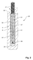
- a fastening arrangement 26 which has a fastening element 41 and an anchoring sleeve 31, which are anchored by means of a hardenable mass 51 in a borehole 6 of a component 5 and which form a fastening device 30.
- the conical extension portions 37 whose diameter widens in the direction of the first end 33 of the sleeve-shaped base body 32, extend helically along the sleeve-shaped base body 32. In the region of the first End 33 is provided on the base body 32, a passage opening 39 for the hardenable mass 51.
- the sleeve-shaped base body 32 has a minimum inner diameter D, which is at least partially slightly smaller than the outer diameter A of the fastening element 41.
- a borehole 6 with the required depth in the component 5 is created.
- the borehole 5 is filled with a corresponding amount of the hardenable mass 51 and then the fastening device 30 with the first end 33 of the anchoring sleeve 31 first inserted into the borehole 5.
- curable mass 51 penetrates into the interior of the inner space between the sleeve-shaped body 32 of the anchoring sleeve 31 and the fastener 41 and on the other hand, the hardenable mass 51 in the gap space between the anchoring sleeve 31 and the wall of the borehole 6 in the direction of the wellbore 7 displaced.
- the fastening device 30 can be loaded to the maximum load level.
- the anchoring sleeve 11 or 31 is inserted first and separately from the fastening element 41 into the created borehole 6 and then subsequently the fastening element 41 into the corresponding anchoring sleeve 11 or 31.
- the borehole 6 can be filled with the hardenable mass 51 before the insertion of the corresponding anchoring sleeve 11 or 31.
- the hardenable mass can be introduced into the borehole 6 into the anchoring sleeve 11 or 31.
- the hardenable mass 51 is filled or introduced only after the insertion of the fastening element 41 into the corresponding anchoring sleeve 11 or 31.
Landscapes
- Engineering & Computer Science (AREA)
- General Engineering & Computer Science (AREA)
- Mechanical Engineering (AREA)
- Joining Of Building Structures In Genera (AREA)
- Dowels (AREA)
- Connection Of Plates (AREA)
Applications Claiming Priority (1)
| Application Number | Priority Date | Filing Date | Title |
|---|---|---|---|
| DE102009028545A DE102009028545A1 (de) | 2009-08-14 | 2009-08-14 | Verankerungshülse |
Publications (3)
| Publication Number | Publication Date |
|---|---|
| EP2284405A2 true EP2284405A2 (fr) | 2011-02-16 |
| EP2284405A3 EP2284405A3 (fr) | 2013-01-23 |
| EP2284405B1 EP2284405B1 (fr) | 2016-08-31 |
Family
ID=43063639
Family Applications (1)
| Application Number | Title | Priority Date | Filing Date |
|---|---|---|---|
| EP10170628.1A Active EP2284405B1 (fr) | 2009-08-14 | 2010-07-23 | Agencement de fixation |
Country Status (7)
| Country | Link |
|---|---|
| US (1) | US9551370B2 (fr) |
| EP (1) | EP2284405B1 (fr) |
| JP (1) | JP5622479B2 (fr) |
| AU (1) | AU2010212262A1 (fr) |
| CA (1) | CA2713057C (fr) |
| DE (1) | DE102009028545A1 (fr) |
| ES (1) | ES2605610T3 (fr) |
Cited By (1)
| Publication number | Priority date | Publication date | Assignee | Title |
|---|---|---|---|---|
| DE102023104456A1 (de) | 2023-02-23 | 2024-08-29 | Adolf Würth GmbH & Co. KG | Befestigungsvorrichtung, Boden und Setzring für einen Verbundanker mit Bohrlochreinigung |
Families Citing this family (6)
| Publication number | Priority date | Publication date | Assignee | Title |
|---|---|---|---|---|
| DE102009028545A1 (de) * | 2009-08-14 | 2011-02-17 | Hilti Aktiengesellschaft | Verankerungshülse |
| JP6991562B2 (ja) * | 2017-11-09 | 2022-01-12 | Fsテクニカル株式会社 | 接着系アンカー用のアンカーボルト、接着系アンカーおよび接着系アンカーの施工方法 |
| KR102604423B1 (ko) * | 2021-11-24 | 2023-11-23 | 주식회사 포스코 | 앵커 조립체 |
| WO2023117734A1 (fr) * | 2021-12-20 | 2023-06-29 | Rotho Blaas Gmbh/Srl | Système de raccordement amélioré pour raccorder des éléments en bois à un élément en béton armé d'un bâtiment, procédé de production du raccordement, et kit de construction |
| JP7179303B1 (ja) * | 2022-03-09 | 2022-11-29 | 中川産業株式会社 | 繊維強化樹脂製筋金棒体の定着具およびその製造方法 |
| CN115898494B (zh) * | 2022-11-24 | 2023-09-08 | 宁波大学 | 一种高延伸率玄武岩纤维防腐锚索及其支护方法 |
Citations (3)
| Publication number | Priority date | Publication date | Assignee | Title |
|---|---|---|---|---|
| EP0426951B1 (fr) | 1989-11-04 | 1994-02-23 | UPAT GMBH & CO | Barre d'ancrage |
| US5628161A (en) | 1995-04-28 | 1997-05-13 | Giannuzzi; Louis N. | Centering sleeve and overflow ring assembly |
| EP0738835B1 (fr) | 1995-04-20 | 1998-12-02 | Adolf Würth GmbH & Co. KG | Cheville à enveloppe en forme de crible |
Family Cites Families (27)
| Publication number | Priority date | Publication date | Assignee | Title |
|---|---|---|---|---|
| DE2059852C2 (de) * | 1970-12-04 | 1983-09-15 | Hilti AG, 9494 Schaan | Klebstoffkörper zum Setzen eines Ankers in einer Bohrung |
| US4094054A (en) * | 1974-10-03 | 1978-06-13 | Artur Fischer | Method of securing an object to a low-strength support structure |
| FR2315568A1 (fr) * | 1975-06-25 | 1977-01-21 | Vape Sa Ets | Dispositif de fixation a vis dans un element de construction en matiere agglomeree |
| US4160614A (en) * | 1978-03-23 | 1979-07-10 | Jennmar Corporation | Expansion shell assembly and method for combining resin bonding and mechanical anchoring of a bolt in a rock formation |
| JPS60113811A (ja) * | 1983-11-25 | 1985-06-20 | 筒中シート防水株式会社 | 気泡コンクリ−トへのねじ固着方法 |
| JPS60134912U (ja) * | 1984-02-21 | 1985-09-07 | 西出 博行 | 壁打込み固定具 |
| DE3712463A1 (de) * | 1987-04-13 | 1988-10-27 | Hilti Ag | Befestigung auf hohlraeume aufweisendem untergrund |
| FR2636685B1 (fr) * | 1988-09-19 | 1991-01-11 | Vape Sa Ets | Dispositif de fixation a vis dans un element de construction en beton |
| JPH02122206U (fr) * | 1989-03-20 | 1990-10-05 | ||
| US5143498A (en) * | 1990-06-21 | 1992-09-01 | Whitman Robert E | Roofing fastening device |
| US5145301A (en) * | 1991-02-13 | 1992-09-08 | Akio Yamamoto | Nail sustainer |
| KR950008328B1 (ko) * | 1991-08-14 | 1995-07-27 | 야마모도 노부꼬 | 못 유지부재 |
| US5219248A (en) * | 1992-05-14 | 1993-06-15 | The Eastern Company | Mine roof expansion anchor with improved bore hole engagement means and method of installation thereof |
| DE4332558A1 (de) * | 1993-09-24 | 1995-03-30 | Fischer Artur Werke Gmbh | Spreizanker aus Metall und Verfahren zu dessen Herstellung |
| DE69505800T2 (de) * | 1994-03-18 | 1999-06-10 | Vape Rail International S.A., St Martin-Du-Fresne | Ankerhülse |
| US5641256A (en) * | 1994-06-09 | 1997-06-24 | Npc, Inc. | Anchoring device for a threaded member |
| US5490750A (en) * | 1994-06-09 | 1996-02-13 | Gundy; William P. | Anchoring device for a threaded member |
| JP2000513086A (ja) * | 1997-06-03 | 2000-10-03 | ウパト ゲゼルシヤフト ミツト ベシユレンクテル ハフツング ウント コンパニー | プラスチック製の固定カートリッジ |
| DE19955684A1 (de) * | 1999-11-19 | 2001-05-23 | Hilti Ag | Ankerstange für Verankerungen mit organischen und/oder anorganischen Mörtelmassen |
| US6393795B1 (en) * | 2000-08-16 | 2002-05-28 | Illinois Tool Works Inc. | Adhesive anchor and system |
| DE10311471A1 (de) * | 2003-03-15 | 2004-09-23 | Fischerwerke Artur Fischer Gmbh & Co. Kg | Gewindeformende Schraube für Untergründe aus harten Vollbaustoffen |
| FR2852613A1 (fr) | 2003-03-20 | 2004-09-24 | Vapr Rail Internat | Procede de reparation d'un ancrage de rail de chemin de fer sur une traverse en bois |
| US6896462B2 (en) * | 2003-09-17 | 2005-05-24 | General Motors Corporation | Mechanical and adhesive fastener unit |
| US7955024B2 (en) * | 2003-12-03 | 2011-06-07 | Ez Set Tile, Inc. | Inlay system for concrete |
| CA2607850C (fr) * | 2006-07-20 | 2015-01-06 | Jennmar Corporation | Boulon d'ancrage |
| US7802951B2 (en) * | 2006-12-18 | 2010-09-28 | Sandisk Corporation | Anti-rotational adhesive insert |
| DE102009028545A1 (de) * | 2009-08-14 | 2011-02-17 | Hilti Aktiengesellschaft | Verankerungshülse |
-
2009
- 2009-08-14 DE DE102009028545A patent/DE102009028545A1/de not_active Withdrawn
-
2010
- 2010-07-23 EP EP10170628.1A patent/EP2284405B1/fr active Active
- 2010-07-23 ES ES10170628.1T patent/ES2605610T3/es active Active
- 2010-08-10 AU AU2010212262A patent/AU2010212262A1/en not_active Abandoned
- 2010-08-12 CA CA2713057A patent/CA2713057C/fr not_active Expired - Fee Related
- 2010-08-13 US US12/856,354 patent/US9551370B2/en not_active Expired - Fee Related
- 2010-08-13 JP JP2010181411A patent/JP5622479B2/ja not_active Expired - Fee Related
Patent Citations (3)
| Publication number | Priority date | Publication date | Assignee | Title |
|---|---|---|---|---|
| EP0426951B1 (fr) | 1989-11-04 | 1994-02-23 | UPAT GMBH & CO | Barre d'ancrage |
| EP0738835B1 (fr) | 1995-04-20 | 1998-12-02 | Adolf Würth GmbH & Co. KG | Cheville à enveloppe en forme de crible |
| US5628161A (en) | 1995-04-28 | 1997-05-13 | Giannuzzi; Louis N. | Centering sleeve and overflow ring assembly |
Cited By (1)
| Publication number | Priority date | Publication date | Assignee | Title |
|---|---|---|---|---|
| DE102023104456A1 (de) | 2023-02-23 | 2024-08-29 | Adolf Würth GmbH & Co. KG | Befestigungsvorrichtung, Boden und Setzring für einen Verbundanker mit Bohrlochreinigung |
Also Published As
| Publication number | Publication date |
|---|---|
| US9551370B2 (en) | 2017-01-24 |
| JP5622479B2 (ja) | 2014-11-12 |
| US20110038686A1 (en) | 2011-02-17 |
| JP2011038639A (ja) | 2011-02-24 |
| CA2713057C (fr) | 2017-05-02 |
| CA2713057A1 (fr) | 2011-02-14 |
| EP2284405B1 (fr) | 2016-08-31 |
| ES2605610T3 (es) | 2017-03-15 |
| DE102009028545A1 (de) | 2011-02-17 |
| AU2010212262A1 (en) | 2011-03-03 |
| EP2284405A3 (fr) | 2013-01-23 |
Similar Documents
| Publication | Publication Date | Title |
|---|---|---|
| DE4310796C2 (de) | Spreizanker | |
| EP1984632B1 (fr) | Cheville expansible | |
| EP2284405B1 (fr) | Agencement de fixation | |
| EP1903220A2 (fr) | Ancre extensible | |
| DE102011083153A1 (de) | Ankerstange | |
| EP1591596B1 (fr) | Goujon noyé | |
| WO2009109300A1 (fr) | Système constitué d'une vis d'ancrage composite et d'un adhésif | |
| EP2354567B1 (fr) | Vis de tige d'encrage | |
| EP2148098A2 (fr) | Elément d'ancrage en forme de plaque annulaire | |
| DE1625337A1 (de) | Aus Spreizteil,Befestigungselement und Huelse bestehender Spreizduebel | |
| EP2513498B1 (fr) | Douille d'ancrage | |
| DE102008010606A1 (de) | Befestigungselement für Holzfaserdämmplatten | |
| EP2691659B1 (fr) | Ancre d'attache et structure de fixation | |
| WO2012152237A1 (fr) | Vis d'ancrage composite | |
| DE3022414A1 (de) | Duebel fuer eine formschluessige verankerung in leichtbauwerkstoffen | |
| EP2119919B1 (fr) | Agencement de fixation | |
| EP1518056A1 (fr) | Piton a expansion en matiere plastique | |
| DE102008030051B4 (de) | Ankerstange zur Verankerung in einem Bohrloch | |
| EP2251555A1 (fr) | Cheville | |
| EP2148100B1 (fr) | Elément d'ancrage | |
| EP2020469A2 (fr) | Cheville destinée à la fixation d'éléments plats en matériau flexible de type mousse | |
| DE2205624A1 (de) | Zylindrischer Spreizdübel mit Ein Satzkern | |
| DE3031047A1 (de) | Spreizduebel aus kunststoff | |
| DE102007035953A1 (de) | Dübel zur Befestigung von plattenförmigen Elementen aus einem schaumstoffartigen nachgiebigen Material | |
| EP2230409A1 (fr) | Douille d'ancrage |
Legal Events
| Date | Code | Title | Description |
|---|---|---|---|
| PUAI | Public reference made under article 153(3) epc to a published international application that has entered the european phase |
Free format text: ORIGINAL CODE: 0009012 |
|
| AK | Designated contracting states |
Kind code of ref document: A2 Designated state(s): AL AT BE BG CH CY CZ DE DK EE ES FI FR GB GR HR HU IE IS IT LI LT LU LV MC MK MT NL NO PL PT RO SE SI SK SM TR |
|
| AX | Request for extension of the european patent |
Extension state: BA ME RS |
|
| PUAL | Search report despatched |
Free format text: ORIGINAL CODE: 0009013 |
|
| AK | Designated contracting states |
Kind code of ref document: A3 Designated state(s): AL AT BE BG CH CY CZ DE DK EE ES FI FR GB GR HR HU IE IS IT LI LT LU LV MC MK MT NL NO PL PT RO SE SI SK SM TR |
|
| AX | Request for extension of the european patent |
Extension state: BA ME RS |
|
| RIC1 | Information provided on ipc code assigned before grant |
Ipc: F16B 39/22 20060101ALI20121214BHEP Ipc: F16B 13/14 20060101AFI20121214BHEP |
|
| 17P | Request for examination filed |
Effective date: 20130723 |
|
| RBV | Designated contracting states (corrected) |
Designated state(s): AL AT BE BG CH CY CZ DE DK EE ES FI FR GB GR HR HU IE IS IT LI LT LU LV MC MK MT NL NO PL PT RO SE SI SK SM TR |
|
| 17Q | First examination report despatched |
Effective date: 20131023 |
|
| GRAP | Despatch of communication of intention to grant a patent |
Free format text: ORIGINAL CODE: EPIDOSNIGR1 |
|
| INTG | Intention to grant announced |
Effective date: 20151209 |
|
| GRAJ | Information related to disapproval of communication of intention to grant by the applicant or resumption of examination proceedings by the epo deleted |
Free format text: ORIGINAL CODE: EPIDOSDIGR1 |
|
| GRAP | Despatch of communication of intention to grant a patent |
Free format text: ORIGINAL CODE: EPIDOSNIGR1 |
|
| INTG | Intention to grant announced |
Effective date: 20160323 |
|
| GRAS | Grant fee paid |
Free format text: ORIGINAL CODE: EPIDOSNIGR3 |
|
| GRAA | (expected) grant |
Free format text: ORIGINAL CODE: 0009210 |
|
| AK | Designated contracting states |
Kind code of ref document: B1 Designated state(s): AL AT BE BG CH CY CZ DE DK EE ES FI FR GB GR HR HU IE IS IT LI LT LU LV MC MK MT NL NO PL PT RO SE SI SK SM TR |
|
| REG | Reference to a national code |
Ref country code: CH Ref legal event code: EP Ref country code: GB Ref legal event code: FG4D Free format text: NOT ENGLISH |
|
| REG | Reference to a national code |
Ref country code: IE Ref legal event code: FG4D Free format text: LANGUAGE OF EP DOCUMENT: GERMAN |
|
| REG | Reference to a national code |
Ref country code: DE Ref legal event code: R096 Ref document number: 502010012287 Country of ref document: DE |
|
| REG | Reference to a national code |
Ref country code: AT Ref legal event code: REF Ref document number: 825256 Country of ref document: AT Kind code of ref document: T Effective date: 20161015 |
|
| REG | Reference to a national code |
Ref country code: LT Ref legal event code: MG4D |
|
| REG | Reference to a national code |
Ref country code: NL Ref legal event code: MP Effective date: 20160831 |
|
| PG25 | Lapsed in a contracting state [announced via postgrant information from national office to epo] |
Ref country code: LT Free format text: LAPSE BECAUSE OF FAILURE TO SUBMIT A TRANSLATION OF THE DESCRIPTION OR TO PAY THE FEE WITHIN THE PRESCRIBED TIME-LIMIT Effective date: 20160831 Ref country code: NO Free format text: LAPSE BECAUSE OF FAILURE TO SUBMIT A TRANSLATION OF THE DESCRIPTION OR TO PAY THE FEE WITHIN THE PRESCRIBED TIME-LIMIT Effective date: 20161130 Ref country code: HR Free format text: LAPSE BECAUSE OF FAILURE TO SUBMIT A TRANSLATION OF THE DESCRIPTION OR TO PAY THE FEE WITHIN THE PRESCRIBED TIME-LIMIT Effective date: 20160831 Ref country code: FI Free format text: LAPSE BECAUSE OF FAILURE TO SUBMIT A TRANSLATION OF THE DESCRIPTION OR TO PAY THE FEE WITHIN THE PRESCRIBED TIME-LIMIT Effective date: 20160831 |
|
| PG25 | Lapsed in a contracting state [announced via postgrant information from national office to epo] |
Ref country code: GR Free format text: LAPSE BECAUSE OF FAILURE TO SUBMIT A TRANSLATION OF THE DESCRIPTION OR TO PAY THE FEE WITHIN THE PRESCRIBED TIME-LIMIT Effective date: 20161201 Ref country code: SE Free format text: LAPSE BECAUSE OF FAILURE TO SUBMIT A TRANSLATION OF THE DESCRIPTION OR TO PAY THE FEE WITHIN THE PRESCRIBED TIME-LIMIT Effective date: 20160831 Ref country code: LV Free format text: LAPSE BECAUSE OF FAILURE TO SUBMIT A TRANSLATION OF THE DESCRIPTION OR TO PAY THE FEE WITHIN THE PRESCRIBED TIME-LIMIT Effective date: 20160831 Ref country code: NL Free format text: LAPSE BECAUSE OF FAILURE TO SUBMIT A TRANSLATION OF THE DESCRIPTION OR TO PAY THE FEE WITHIN THE PRESCRIBED TIME-LIMIT Effective date: 20160831 |
|
| REG | Reference to a national code |
Ref country code: ES Ref legal event code: FG2A Ref document number: 2605610 Country of ref document: ES Kind code of ref document: T3 Effective date: 20170315 |
|
| PG25 | Lapsed in a contracting state [announced via postgrant information from national office to epo] |
Ref country code: RO Free format text: LAPSE BECAUSE OF FAILURE TO SUBMIT A TRANSLATION OF THE DESCRIPTION OR TO PAY THE FEE WITHIN THE PRESCRIBED TIME-LIMIT Effective date: 20160831 Ref country code: EE Free format text: LAPSE BECAUSE OF FAILURE TO SUBMIT A TRANSLATION OF THE DESCRIPTION OR TO PAY THE FEE WITHIN THE PRESCRIBED TIME-LIMIT Effective date: 20160831 |
|
| PG25 | Lapsed in a contracting state [announced via postgrant information from national office to epo] |
Ref country code: SM Free format text: LAPSE BECAUSE OF FAILURE TO SUBMIT A TRANSLATION OF THE DESCRIPTION OR TO PAY THE FEE WITHIN THE PRESCRIBED TIME-LIMIT Effective date: 20160831 Ref country code: SK Free format text: LAPSE BECAUSE OF FAILURE TO SUBMIT A TRANSLATION OF THE DESCRIPTION OR TO PAY THE FEE WITHIN THE PRESCRIBED TIME-LIMIT Effective date: 20160831 Ref country code: DK Free format text: LAPSE BECAUSE OF FAILURE TO SUBMIT A TRANSLATION OF THE DESCRIPTION OR TO PAY THE FEE WITHIN THE PRESCRIBED TIME-LIMIT Effective date: 20160831 Ref country code: PL Free format text: LAPSE BECAUSE OF FAILURE TO SUBMIT A TRANSLATION OF THE DESCRIPTION OR TO PAY THE FEE WITHIN THE PRESCRIBED TIME-LIMIT Effective date: 20160831 Ref country code: PT Free format text: LAPSE BECAUSE OF FAILURE TO SUBMIT A TRANSLATION OF THE DESCRIPTION OR TO PAY THE FEE WITHIN THE PRESCRIBED TIME-LIMIT Effective date: 20170102 Ref country code: BG Free format text: LAPSE BECAUSE OF FAILURE TO SUBMIT A TRANSLATION OF THE DESCRIPTION OR TO PAY THE FEE WITHIN THE PRESCRIBED TIME-LIMIT Effective date: 20161130 Ref country code: CZ Free format text: LAPSE BECAUSE OF FAILURE TO SUBMIT A TRANSLATION OF THE DESCRIPTION OR TO PAY THE FEE WITHIN THE PRESCRIBED TIME-LIMIT Effective date: 20160831 |
|
| REG | Reference to a national code |
Ref country code: DE Ref legal event code: R097 Ref document number: 502010012287 Country of ref document: DE |
|
| REG | Reference to a national code |
Ref country code: FR Ref legal event code: PLFP Year of fee payment: 8 |
|
| PLBE | No opposition filed within time limit |
Free format text: ORIGINAL CODE: 0009261 |
|
| STAA | Information on the status of an ep patent application or granted ep patent |
Free format text: STATUS: NO OPPOSITION FILED WITHIN TIME LIMIT |
|
| 26N | No opposition filed |
Effective date: 20170601 |
|
| PG25 | Lapsed in a contracting state [announced via postgrant information from national office to epo] |
Ref country code: SI Free format text: LAPSE BECAUSE OF FAILURE TO SUBMIT A TRANSLATION OF THE DESCRIPTION OR TO PAY THE FEE WITHIN THE PRESCRIBED TIME-LIMIT Effective date: 20160831 |
|
| REG | Reference to a national code |
Ref country code: IE Ref legal event code: MM4A |
|
| PG25 | Lapsed in a contracting state [announced via postgrant information from national office to epo] |
Ref country code: IE Free format text: LAPSE BECAUSE OF NON-PAYMENT OF DUE FEES Effective date: 20170723 |
|
| REG | Reference to a national code |
Ref country code: BE Ref legal event code: MM Effective date: 20170731 |
|
| PG25 | Lapsed in a contracting state [announced via postgrant information from national office to epo] |
Ref country code: LU Free format text: LAPSE BECAUSE OF NON-PAYMENT OF DUE FEES Effective date: 20170723 |
|
| REG | Reference to a national code |
Ref country code: FR Ref legal event code: PLFP Year of fee payment: 9 |
|
| PG25 | Lapsed in a contracting state [announced via postgrant information from national office to epo] |
Ref country code: BE Free format text: LAPSE BECAUSE OF NON-PAYMENT OF DUE FEES Effective date: 20170731 |
|
| REG | Reference to a national code |
Ref country code: AT Ref legal event code: MM01 Ref document number: 825256 Country of ref document: AT Kind code of ref document: T Effective date: 20170723 |
|
| PG25 | Lapsed in a contracting state [announced via postgrant information from national office to epo] |
Ref country code: MT Free format text: LAPSE BECAUSE OF FAILURE TO SUBMIT A TRANSLATION OF THE DESCRIPTION OR TO PAY THE FEE WITHIN THE PRESCRIBED TIME-LIMIT Effective date: 20160831 |
|
| PG25 | Lapsed in a contracting state [announced via postgrant information from national office to epo] |
Ref country code: AL Free format text: LAPSE BECAUSE OF FAILURE TO SUBMIT A TRANSLATION OF THE DESCRIPTION OR TO PAY THE FEE WITHIN THE PRESCRIBED TIME-LIMIT Effective date: 20160831 |
|
| PG25 | Lapsed in a contracting state [announced via postgrant information from national office to epo] |
Ref country code: AT Free format text: LAPSE BECAUSE OF NON-PAYMENT OF DUE FEES Effective date: 20170723 |
|
| PG25 | Lapsed in a contracting state [announced via postgrant information from national office to epo] |
Ref country code: MC Free format text: LAPSE BECAUSE OF FAILURE TO SUBMIT A TRANSLATION OF THE DESCRIPTION OR TO PAY THE FEE WITHIN THE PRESCRIBED TIME-LIMIT Effective date: 20160831 Ref country code: HU Free format text: LAPSE BECAUSE OF FAILURE TO SUBMIT A TRANSLATION OF THE DESCRIPTION OR TO PAY THE FEE WITHIN THE PRESCRIBED TIME-LIMIT; INVALID AB INITIO Effective date: 20100723 |
|
| PG25 | Lapsed in a contracting state [announced via postgrant information from national office to epo] |
Ref country code: CY Free format text: LAPSE BECAUSE OF NON-PAYMENT OF DUE FEES Effective date: 20160831 |
|
| PGFP | Annual fee paid to national office [announced via postgrant information from national office to epo] |
Ref country code: ES Payment date: 20190822 Year of fee payment: 10 |
|
| PG25 | Lapsed in a contracting state [announced via postgrant information from national office to epo] |
Ref country code: MK Free format text: LAPSE BECAUSE OF FAILURE TO SUBMIT A TRANSLATION OF THE DESCRIPTION OR TO PAY THE FEE WITHIN THE PRESCRIBED TIME-LIMIT Effective date: 20160831 |
|
| PG25 | Lapsed in a contracting state [announced via postgrant information from national office to epo] |
Ref country code: TR Free format text: LAPSE BECAUSE OF FAILURE TO SUBMIT A TRANSLATION OF THE DESCRIPTION OR TO PAY THE FEE WITHIN THE PRESCRIBED TIME-LIMIT Effective date: 20160831 |
|
| PG25 | Lapsed in a contracting state [announced via postgrant information from national office to epo] |
Ref country code: IS Free format text: LAPSE BECAUSE OF FAILURE TO SUBMIT A TRANSLATION OF THE DESCRIPTION OR TO PAY THE FEE WITHIN THE PRESCRIBED TIME-LIMIT Effective date: 20161231 |
|
| REG | Reference to a national code |
Ref country code: ES Ref legal event code: FD2A Effective date: 20211230 |
|
| PG25 | Lapsed in a contracting state [announced via postgrant information from national office to epo] |
Ref country code: ES Free format text: LAPSE BECAUSE OF NON-PAYMENT OF DUE FEES Effective date: 20200724 |
|
| PGFP | Annual fee paid to national office [announced via postgrant information from national office to epo] |
Ref country code: DE Payment date: 20250722 Year of fee payment: 16 |
|
| PGFP | Annual fee paid to national office [announced via postgrant information from national office to epo] |
Ref country code: IT Payment date: 20250724 Year of fee payment: 16 |
|
| PGFP | Annual fee paid to national office [announced via postgrant information from national office to epo] |
Ref country code: GB Payment date: 20250722 Year of fee payment: 16 |
|
| PGFP | Annual fee paid to national office [announced via postgrant information from national office to epo] |
Ref country code: FR Payment date: 20250725 Year of fee payment: 16 |
|
| PGFP | Annual fee paid to national office [announced via postgrant information from national office to epo] |
Ref country code: CH Payment date: 20250801 Year of fee payment: 16 |