EP2284453A2 - Absorbeur destiné à chauffer un fluide - Google Patents
Absorbeur destiné à chauffer un fluide Download PDFInfo
- Publication number
- EP2284453A2 EP2284453A2 EP10172260A EP10172260A EP2284453A2 EP 2284453 A2 EP2284453 A2 EP 2284453A2 EP 10172260 A EP10172260 A EP 10172260A EP 10172260 A EP10172260 A EP 10172260A EP 2284453 A2 EP2284453 A2 EP 2284453A2
- Authority
- EP
- European Patent Office
- Prior art keywords
- pipe
- absorber according
- absorber
- manifold
- base
- Prior art date
- Legal status (The legal status is an assumption and is not a legal conclusion. Google has not performed a legal analysis and makes no representation as to the accuracy of the status listed.)
- Withdrawn
Links
- 239000006096 absorbing agent Substances 0.000 title claims abstract description 85
- 238000010438 heat treatment Methods 0.000 title claims description 12
- 239000012530 fluid Substances 0.000 title claims description 8
- 230000006641 stabilisation Effects 0.000 claims description 44
- 238000011105 stabilization Methods 0.000 claims description 44
- 230000000087 stabilizing effect Effects 0.000 claims description 9
- 238000004049 embossing Methods 0.000 claims description 5
- 238000007599 discharging Methods 0.000 claims 1
- 238000009826 distribution Methods 0.000 description 24
- XLYOFNOQVPJJNP-UHFFFAOYSA-N water Substances O XLYOFNOQVPJJNP-UHFFFAOYSA-N 0.000 description 13
- 239000004033 plastic Substances 0.000 description 9
- 239000007788 liquid Substances 0.000 description 8
- 230000009182 swimming Effects 0.000 description 7
- 239000002184 metal Substances 0.000 description 6
- 229910052751 metal Inorganic materials 0.000 description 6
- 230000035882 stress Effects 0.000 description 6
- 238000005452 bending Methods 0.000 description 5
- 238000005476 soldering Methods 0.000 description 5
- 238000009434 installation Methods 0.000 description 4
- 239000000463 material Substances 0.000 description 4
- 238000011084 recovery Methods 0.000 description 4
- 238000007789 sealing Methods 0.000 description 4
- 230000015572 biosynthetic process Effects 0.000 description 3
- 239000002131 composite material Substances 0.000 description 3
- 230000000694 effects Effects 0.000 description 3
- 238000005755 formation reaction Methods 0.000 description 3
- 230000020169 heat generation Effects 0.000 description 3
- 238000000034 method Methods 0.000 description 3
- 230000000284 resting effect Effects 0.000 description 3
- 238000003466 welding Methods 0.000 description 3
- 239000004743 Polypropylene Substances 0.000 description 2
- 238000004026 adhesive bonding Methods 0.000 description 2
- 230000006835 compression Effects 0.000 description 2
- 238000007906 compression Methods 0.000 description 2
- 238000005336 cracking Methods 0.000 description 2
- 239000007789 gas Substances 0.000 description 2
- 238000004519 manufacturing process Methods 0.000 description 2
- -1 polypropylene Polymers 0.000 description 2
- 229920001155 polypropylene Polymers 0.000 description 2
- 239000002689 soil Substances 0.000 description 2
- 229910000679 solder Inorganic materials 0.000 description 2
- ZAMOUSCENKQFHK-UHFFFAOYSA-N Chlorine atom Chemical compound [Cl] ZAMOUSCENKQFHK-UHFFFAOYSA-N 0.000 description 1
- RYGMFSIKBFXOCR-UHFFFAOYSA-N Copper Chemical compound [Cu] RYGMFSIKBFXOCR-UHFFFAOYSA-N 0.000 description 1
- 241001295925 Gegenes Species 0.000 description 1
- 238000005299 abrasion Methods 0.000 description 1
- 238000010521 absorption reaction Methods 0.000 description 1
- 230000002411 adverse Effects 0.000 description 1
- 230000032683 aging Effects 0.000 description 1
- 239000011324 bead Substances 0.000 description 1
- 238000000071 blow moulding Methods 0.000 description 1
- 229910052801 chlorine Inorganic materials 0.000 description 1
- 239000000460 chlorine Substances 0.000 description 1
- 229910052802 copper Inorganic materials 0.000 description 1
- 239000010949 copper Substances 0.000 description 1
- 238000005520 cutting process Methods 0.000 description 1
- 238000006073 displacement reaction Methods 0.000 description 1
- 238000004134 energy conservation Methods 0.000 description 1
- 238000001125 extrusion Methods 0.000 description 1
- 238000010101 extrusion blow moulding Methods 0.000 description 1
- 238000005338 heat storage Methods 0.000 description 1
- 230000001771 impaired effect Effects 0.000 description 1
- 210000004072 lung Anatomy 0.000 description 1
- 238000003825 pressing Methods 0.000 description 1
- 230000005855 radiation Effects 0.000 description 1
- 230000035939 shock Effects 0.000 description 1
- 210000002023 somite Anatomy 0.000 description 1
- 229910001220 stainless steel Inorganic materials 0.000 description 1
- 239000010935 stainless steel Substances 0.000 description 1
- 238000003860 storage Methods 0.000 description 1
- 230000008646 thermal stress Effects 0.000 description 1
- 239000002351 wastewater Substances 0.000 description 1
Images


Classifications
-
- F—MECHANICAL ENGINEERING; LIGHTING; HEATING; WEAPONS; BLASTING
- F24—HEATING; RANGES; VENTILATING
- F24S—SOLAR HEAT COLLECTORS; SOLAR HEAT SYSTEMS
- F24S10/00—Solar heat collectors using working fluids
- F24S10/70—Solar heat collectors using working fluids the working fluids being conveyed through tubular absorbing conduits
-
- F—MECHANICAL ENGINEERING; LIGHTING; HEATING; WEAPONS; BLASTING
- F24—HEATING; RANGES; VENTILATING
- F24S—SOLAR HEAT COLLECTORS; SOLAR HEAT SYSTEMS
- F24S80/00—Details, accessories or component parts of solar heat collectors not provided for in groups F24S10/00-F24S70/00
- F24S80/30—Arrangements for connecting the fluid circuits of solar collectors with each other or with other components, e.g. pipe connections; Fluid distributing means, e.g. headers
-
- Y—GENERAL TAGGING OF NEW TECHNOLOGICAL DEVELOPMENTS; GENERAL TAGGING OF CROSS-SECTIONAL TECHNOLOGIES SPANNING OVER SEVERAL SECTIONS OF THE IPC; TECHNICAL SUBJECTS COVERED BY FORMER USPC CROSS-REFERENCE ART COLLECTIONS [XRACs] AND DIGESTS
- Y02—TECHNOLOGIES OR APPLICATIONS FOR MITIGATION OR ADAPTATION AGAINST CLIMATE CHANGE
- Y02B—CLIMATE CHANGE MITIGATION TECHNOLOGIES RELATED TO BUILDINGS, e.g. HOUSING, HOUSE APPLIANCES OR RELATED END-USER APPLICATIONS
- Y02B10/00—Integration of renewable energy sources in buildings
- Y02B10/20—Solar thermal
-
- Y—GENERAL TAGGING OF NEW TECHNOLOGICAL DEVELOPMENTS; GENERAL TAGGING OF CROSS-SECTIONAL TECHNOLOGIES SPANNING OVER SEVERAL SECTIONS OF THE IPC; TECHNICAL SUBJECTS COVERED BY FORMER USPC CROSS-REFERENCE ART COLLECTIONS [XRACs] AND DIGESTS
- Y02—TECHNOLOGIES OR APPLICATIONS FOR MITIGATION OR ADAPTATION AGAINST CLIMATE CHANGE
- Y02E—REDUCTION OF GREENHOUSE GAS [GHG] EMISSIONS, RELATED TO ENERGY GENERATION, TRANSMISSION OR DISTRIBUTION
- Y02E10/00—Energy generation through renewable energy sources
- Y02E10/40—Solar thermal energy, e.g. solar towers
- Y02E10/44—Heat exchange systems
Definitions
- the present invention relates to an absorber for heating a fluid, comprising at least one distributor pipe for supply or discharge of the fluid to be heated, having a longitudinal axis and a manifold wall over the length of pipe connections are distributed for connecting collector pipes.
- the absorber is basically flowed through by the fluid to be heated, wherein the fluid stream receives heat from the absorber and is discharged therefrom as heated gas or as a heated liquid.
- Such absorbers are used for example in the form of solar collectors in various embodiments for heating the water of swimming pools, fixed or freely deployable swimming pools, children's pools in the indoor or outdoor area, garden showers and the like, and in the course of energy conservation and use of renewable energy increasingly also for heat generation or recovery in the field of domestic water heating and domestic heating in conjunction with heat storage.
- the heat transfer medium comes in the first-mentioned field of application exclusively water into consideration.
- other liquids or gases and other types of absorbers such as in the field of geothermal energy embedded in the earth geothermal absorber or absorber channel mats for heat recovery from wastewater such as in the DE 20 2004 018 084 U1 described.
- the solar collector consists of a mat-shaped arrangement consisting of numerous, parallel to each other extending collector tubes is formed.
- the collector tubes are formed as corrugated tubes and extend between a common manifold and a common manifold. About the manifold, the water to be heated is supplied to the collector tubes and discharged from the manifold again.
- manifold and manifold will be summarized below under the term "manifold".
- Manifold tubes have a much larger inside diameter than the collector tubes.
- distribution pipes contribute because of their property as a lateral boundary of the absorber mat for shape stabilization of the same and generally have a certain flexural rigidity. This also facilitates the production of watertight connections to the liquid inlets and outlets, but makes it difficult to transport the distribution pipes, since they can not be rolled up. Therefore, the distribution pipes are usually composed of shorter individual pieces, for example by gluing. All tubes of the known absorber are made of plastic. A special focus is on the frost resistance of the known absorber.
- Another type of solar absorber is used for heat generation or - recovery in the field of domestic water heating and domestic heating.
- high temperatures are usually desired above 60 ° C, which is achieved by a discontinuous operation of the absorber by water or another heat transfer medium remains within the absorber and is heated therein until it has reached a predetermined target temperature.
- a solar absorber is from the DE 100 39 111 B4 known. It consists of metal and is composed of so-called strip absorbers, which consist of capillary tubes made of copper, which are connected to a collection tube made of stainless steel by soldering. In order to improve the frost resistance of the absorber is proposed to form the manifold with corrugated pipe profile.
- Soldering the capillary tubes during the soldering process involves the risk that the wall of the collecting tube, which is designed as a corrugated tube and therefore thin, is impaired or even damaged.
- the thermal loading during application of the liquid soldering material can adversely affect the course of force lines and cause increased mechanical stresses in the region of the solder joint. Continuous deformation leads to fatigue of the material and finally to breakage or cracking in the area of the solder joint. Apart from that, the assembly is relatively expensive.
- connection of manifold sections with each other or with inlet and outlet pipes or other plastic connecting elements is usually done by gluing or welding.
- Rigid plastic distribution pipes have a smooth outer wall, so that liquid-tight connections in the form of pipe sockets can be attached to the ends of the distribution pipe or to intermediate pieces, wherein the smooth cylinder jacket surface can serve as a sealing surface.
- the collector tubes are as close as possible to each other, so that a largely closed absorber surface is provided.
- a narrow arrangement of the collector tubes between the respective connecting pieces only a short distributor tube length section remains, which is available for fixing and sealing connections. This makes it difficult to produce a reliable, tight connection of two manifold sections with each other or with other connectors such as end caps, branches, temperature or pressure sensors.
- manifold tube length portion available for end ports could be increased by off-centering the manifold between two collector tube ports, the remaining manifold length is lengthened at the expense of the truncated manifold tube length. On the one hand, however, this leads to loss of material and, on the other hand at different distances between the collector tubes, which is not desirable for aesthetic reasons and in view of a high efficiency.
- connection method has proven itself in the use of rigid distribution pipes made of plastic with a smooth outer wall.
- bonds or welds are subject to fatigue that can lead to leaks and breakage over time.
- Such stabilization profiles for the lateral fixation of collector tubes of a solar collector are also known from EP 1 413 836 A2 known.
- the rigid stabilization profiles reduce the effect of shear forces on the collector tubes and thus give the absorber mat a total of a certain rigidity.
- the stabilization profiles are not windable and difficult to transport.
- the stabilization profiles are therefore usually assembled on site from relatively short stabilization profile sections with lengths of less than 1 m by means of mechanical fasteners such as screws, rivets and clamps. These assembly work require a lot of effort, especially for large-area absorber mats.
- the stiffness of the absorber mat caused by rigid stabilization profiles may be undesirable for some applications.
- Examples include solar collectors for resting on curved or wavy surfaces, such as walls or uneven floor surfaces, or geothermal absorbers for laying in the ground, where either an exact and stable and thus complex relining or a certain form adaptability to the respective support surface Reduction of bending forces during application of the soil and pressure loads by acting weight is desired.
- the present invention has for its object to provide an absorber, which is characterized by simple and safe mountability, frost resistance, fatigue resistance and high efficiency and also meets the requirements for an aesthetic appearance.
- a base is provided, which is liquid-tightly connected to the collector tube wall, and are formed on the directly or indirectly via an intermediate piece two or more pipe connection piece.
- Pipelines with manifolds are particularly advantageous at the ends of the manifold and in joint areas with other components, since they provide the same Increase manifold length, which is available for connection or extension, as already explained above.
- the manifold may be made of metal or plastic.
- the base of the pipe connections can be detachably or non-detachably connected to the distribution pipe, for example by a liquid-tight plug connection, by screwing, by soldering or welding.
- the base is an integral part of the manifold.
- Manifold and socket form an integral composite, so they are made in one piece and are advantageously formed in the same operation. Examples include a continuous extrusion blow molding or a batch blow molding process.
- the integral composite has the advantage that the expense of the subsequent formation of a positive and tight connection between the manifold and socket (such as by welding plastic parts) is eliminated as well as the usually associated with thermal stress on the manifold. A disturbance of the given during the production of the manifold pipe lines of force (with rather low mechanical stresses) by a subsequent attachment of the pipe connection socket is avoided, and thus the formation of voltage spikes.
- the integrally molded base thus contributes to a lower susceptibility to cracking of the absorber even with ongoing deformation forces.
- the base branches into a first pipe connecting piece and into a second pipe connecting piece.
- collector tubes are mounted on a base, the greater are the forces acting on the base and the requirements of its mechanical stability. With two collector tubes per socket, the above-mentioned advantages can be achieved with a relatively small base wall thickness.
- the two pipe connection pieces may for example be connected to a Y-shaped or T-shaped base.
- the base is L-shaped, with a connected to the manifold wall, first leg, and with a parallel to the manifold wall extending second leg, with which the first and the second pipe connection piece are connected.
- the minimum length of the second leg is given by the distance of the attached collector tubes.
- the first leg connected to the distributor tube is preferably shorter than the second leg.
- This embodiment is characterized by a particularly good frost resistance, when the first pipe connection piece has a first pipe connection piece longitudinal axis running perpendicular to the distributor pipe wall, which extends substantially coaxially to the longitudinal axis of the first socket leg.
- the first base leg and / or the second base leg have a non-round inner cross section.
- a non-round inner cross-section of the base leg allows a greater change in internal pressure than a round inner cross section. This results in a better frost resistance.
- the base portion connected to the manifold tube typically has a circular cross-section for ease of sealing.
- this base region can also have any other cross-sectional shape.
- the first base leg has a non-round cross section with a longer dimension (L L ) in the direction of the distributor tube longitudinal axis and perpendicular thereto a shorter dimension (L K ).
- the base cross-section - as seen in the flow direction - is formed, for example, rounded rectangular to oval.
- the manifold is provided with a corrugated profile.
- the distributor tube accordingly has at least one longitudinal section on a corrugated profile with a wave-shaped changing outer diameter.
- the manifold with corrugated tube profile is characterized by a certain flexibility on the one hand and by a high structural rigidity against external pressure at relatively low wall thickness on the other. It can be available in sections of predetermined length or wound up in roll form, which simplifies storage and facilitates transport to the job site.
- the manifold can alternately have length sections with corrugated profile and with smooth profile over its length without significant loss of flexibility and frost resistance. Smooth profile areas are relatively easy to seal and can be provided for example between pipe connection for the purpose of cutting at these locations.
- the manifold is provided with a smooth wall, wherein it has prefabricated holes for receiving the pipe connections
- Distribution pipes with a smooth wall are simpler and cheaper to produce than corrugated pipes. They have a higher flexural rigidity and are relatively easy to seal. Straight tubes are particularly preferred for large manifold diameters and in applications where flexibility and frost resistance of the absorber do not play an important role.
- the prefabricated holes serve to accommodate the pipe connections by means of threaded or plug connections.
- the pedestals are arranged along a common longitudinal side of the distributor tube wall, and on the longitudinal side opposite the common longitudinal side, a plurality of embossing elements for stabilizing the shape is provided.
- the embossing elements are machine-made formations in the area of the distributor tube wall, each of which approximates a pipe connection approximately-ideally in the ideal case.
- the embossing elements are formed as an annular or elongated depression or elevation with approximately the dimensions in the foot region of the base.
- the embossing elements cause a compensation of mechanical stresses that would be generated as a result of integrated only on one side in the manifold pipe wall pipe connections, and they thus contribute to a better dimensional stability and tightness of the absorber. In addition, they increase the rigidity of the manifold.
- each base is opposed by a stamping element on the opposite side of the manifold wall.
- the stabilization profiles run transversely to the collector tubes and take shear forces away from the collector tubes. This is particularly useful when the manifold or the manifolds of the absorber according to the invention are formed as corrugated pipe and therefore have a certain flexibility.
- the stabilization profiles also contribute to the shape stabilization of the mat-shaped arrangement. For applications where high dimensional stability is desired, a greater number of such stabilization profiles and / or stiffer stabilization profiles are used.
- the holding profiles usually show upwardly open, semicircular recesses for receiving the collector tubes. The diameter of the recesses is adapted to the diameter of the collector tubes and formed generally semi-circular in shape.
- the stabilization profile is composed of a plurality of stabilization profile sections, wherein at least two stabilization profile sections over a distance overlap such that each at least one recess and a land area between two recesses are aligned, wherein the land areas lie with a planar contact surface together and by means of a common bracket be overruled.
- the stabilization profiles are assembled from intermittently adjacent sections and the sections are connected to one another by means of a clamp.
- the clip is flipped cap-like on the end webs and locked, where it can be formed with a conically widening outward cavity, which facilitates sliding on the end webs. Furthermore, it may have an abutment that ensures a catch with the end webs.
- a clamp which has a cavity with plate fixed therein, wherein the plate inserts when placing the clip in a slot which traverses the adjacent web portions.
- the plate is pressed when placing the clip in the slot, which traverses the two adjoining web portions.
- the rigid plate is connected to the bracket and prevents mutual displacement of the web portions in the direction of the profile longitudinal axis. As a result, shear forces on the collector tubes, which are fixed in the stabilization profile, largely prevented.
- the clamp prevents deflection of the plate from the slot and a drift apart of the web portions in the direction transverse to the profile longitudinal axis.
- the clip comprises a foot which extends in the direction of both retaining profile sections, and rests on each of which a collector tube.
- the stabilization profile receptacles for the collector tubes are interconnected by webs which run in a central axis of the stabilization profile.
- a curved or twisted band-shaped structure - comparable to a helical line - has a greater length or a smaller length at the edges than in the center.
- the webs over which the stabilization profile receptacles are connected to each other run exactly or approximately in this central axis of the stabilization profile. As a result, they experience no (or only a small) compression or elongation in a twisting or bending of the profile, so that the webs little resistance oppose these deformations. This results in a higher flexibility of the stabilization profile.
- This embodiment of the absorber according to the invention which allows despite high orientation and flexibility of the absorber mat in the direction de mat standards despite forced alignment and fixation of the collector tubes by stabilization, is particularly well suited for installation on uneven surfaces, especially for installation in the ground.
- the flat arrangement of the collector tubes can easily adjust to irregularities of the pad.
- the stabilization profiles of an absorber mat can be arranged, for example, so that one and the same collector tube is always clipped in upwardly open receptacles and the adjacent collector tubes always in downwardly open shots.
- one and the same collector tube is clipped alternately in an upwardly open receptacle and in a downwardly open receptacle, so that there is a weave between the stabilization profiles and the collector tubes, which leads to a particularly good fixation of the collector tubes and a high stability flat arrangement of the absorber mat contributes.
- the distribution pipes and the collector pipes are made of the same plastic. Fügeeducationen the components show together because of each of the same coefficient of thermal expansion low sealing and aging problems, which is also noticeable in terms of a good frost resistance.
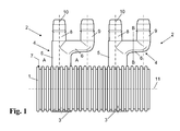
- FIG. 1 schematically shows a manifold 1 for an absorber for heating the water of a swimming pool.
- the distribution pipe 1 is formed as a corrugated pipe and is manufactured by means of an extrusion blown polypropylene.
- tube connections 2 and each tube connection 2 opposite a so-called bead 3 are formed as integral components of the distributor tube 1.
- the pipe connection 2 consists of a base 4 with a cross-sectionally L-shaped profile, wherein the shorter leg 5 of the profile is connected to the wall 7 of the manifold 1 and the longer leg 6 of the L-profile two pipe connection pieces 8, 9 for the connection with a collector tube (in the FIG. 1 not shown) carries.
- the central axes 10 of pipe connection piece 8 and short base legs 5 are coaxial.
- the cross section of the short base leg 5 is formed substantially rectangular with rounded edges, as seen from the top view of FIG. 2 seen.
- the longer side measures 2.5 cm and the short side measures 2 cm.
- the rectangular shape and the comparatively large base dimensions ensure a high mechanical stability of the pipe connection 1 and allow a change in shape when an internal pressure is applied, as indicated by the dashed lines and the block arrow 20.
- the cross section of the longer base leg 6 shows triangular shape with rounded corners, as seen from FIG. 3 seen. This also results in a better shape change capacity at internal pressure and thus a higher frost resistance.
- the deformability is indicated by dashed lines and block arrow 30.
- FIG. 4a shows a pipe connection with triple branching of the base 41
- FIG. 4b shows a two-branched base 42 with T-profile
- Figure 4c shows a two-branched base 43 with Y-profile, which branches into the two pipe connections 44, 45.
- FIG. 5 shows an alternative embodiment using a thick-walled manifold tube 50 with smooth wall 51 and an outer diameter of 150 mm.
- bores 52 are provided along the distributor tube longitudinal axis at regular intervals, in each of which a connection sleeve 53 is inserted.
- a pipe connection 54 protrudes into the bore of the distributor pipe 50. The seal takes place as a result of the profiling of the pipe connection 54 by pressing the connection sleeve 53 against the pipe inner wall FIG.
- the manifold 51 is composed of two sections with end flanges 60 shock white.
- the connection of the sections is done by screwing the flanges 60, between which an O-ring 61 is inserted. This connection is facilitated by the greater distance between the sockets 59, which results as a result of the pipe connections 54 according to the invention.
- the greater distance also provides a larger support surface for holders for the absorber.
- wider holding means such as hose clamps or preferably rubber bands, can be used so that the holding forces are distributed over a larger area.
- lower surface loads act on the distribution pipes and it is produced little abrasion, which is particularly desirable in the thin-walled distribution pipes.
- FIG. 6 schematically shows diagonal absorber for use for heating the water for a swimming pool according to the so-called Tichelmann principle.
- the absorber mat 62 consists essentially of two frontally arranged distribution pipes 63, 64, which are each equipped with pipe connections 65 according to the invention and are connected to each other via a plurality of parallel collector pipes 66 extending from each other.
- the collector tubes 66 and the manifolds 63, 64 and the pipe connections 65 are made of polypropylene, which is stabilized against UV radiation and resistant to chlorine-containing water.
- the water to be heated passes through the manifold 63, which extends over the entire inlet side of the absorber mat 62 approximately uniformly in the collector tubes 66, flows through them under heat absorption in the direction indicated by the direction arrows and occurs on the opposite side in the distributor Discharge 64 (manifold), from where it exits through the outlet again from the absorber mat 62 and enters a (not shown in the figure) swimming pool.
- FIG. 6 it can be seen that the center distance A1 of the pipe connections 65 is twice as large as the center distance A2 of the collector pipes 66. This is made possible by the use of pipe connections 65 with branching elements, such as for example branching 67 with an L-shaped profile, as in FIG FIG. 6 indicated schematically.
- FIG. 7 schematically shows an alternative embodiment of an absorber mat 70 according to the invention in a cutout with two composite Distribution pipes 73.
- the distribution pipes 73 are connected to each other by means of a collar 74.
- Each manifold 73 has only at one end a branching pipe connection 75. Otherwise, usual pipe connection pieces 71 are provided without branching. By using pipe connections 75 with branching in the end region, the pipe length available for connection by means of sleeve 74 is increased.
- FIG. 8 shows a cross section of a stabilizing profile 80 having a plurality of receptacles 81 for receiving the collector tubes.
- the recordings are alternately open upwards or downwards and connected to one another by means of webs 82.
- the webs 82 and the centers 83 of the receptacles 81 run in the central axis 84 of the stabilizing profile 80. This results in a higher flexibility of the stabilizing profile 80, so that this is particularly suitable for resting on non-planar surfaces and in the bottom area.
- the collector tubes are clipped alternately from below and from above into the receptacles 81. This results in a web-like connection between stabilizing profile 80 and collector tubes, which leads to increased mechanical stability.
- FIG. 9 shows an alternative embodiment of a stabilization profile 90 for receiving collector tubes 91.
- the stabilizing profile 90 has an L-shape and has upwardly open, substantially semicircular receptacles for the collector tubes 91, which are interconnected by webs 93.
- the webs 93 between the collector tube receptacles each show a longitudinal slot 94 (in an alternative embodiment, only the webs 93 at the profile ends a longitudinal slot).
- the stabilization profile 90 is made of partially overlapping sections 98; 99 (see FIG. 10 ).
- the sections 98, 99 are here with a flat side (back of the long L-leg) to each other so that the receptacles for the collector tubes 91 and the slots 94 are aligned.
- a metal plate 95 is inserted into the common slot 94, which fixes the two overlapping sections 98, 99 relative to one another by preventing sliding in the stabilization profile longitudinal axis.
- a clip 96 is set, which laterally overhangs the two webs 93 and thus prevents drifting apart in the direction perpendicular to the stabilization profile longitudinal axis.
- the metal plate 95 is inserted into a cavity of the clip 96, so that when placing the clip 96 at the same time the metal plate 95 is pressed into the slots.
- the bracket 96 is provided with a foot 97 which extends on both sides in the direction of the collector tubes 91 and on which the collector tubes 91 rest.
- FIG. 10 schematically shows the clip 96 including metal plate 95 and two-sided foot 97 in a plan view (in section).
Landscapes
- Engineering & Computer Science (AREA)
- Physics & Mathematics (AREA)
- Life Sciences & Earth Sciences (AREA)
- Sustainable Development (AREA)
- Sustainable Energy (AREA)
- Thermal Sciences (AREA)
- Chemical & Material Sciences (AREA)
- Combustion & Propulsion (AREA)
- Mechanical Engineering (AREA)
- General Engineering & Computer Science (AREA)
- Steam Or Hot-Water Central Heating Systems (AREA)
- Rigid Pipes And Flexible Pipes (AREA)
Applications Claiming Priority (1)
| Application Number | Priority Date | Filing Date | Title |
|---|---|---|---|
| DE102009037064.1A DE102009037064B4 (de) | 2009-08-13 | 2009-08-13 | Absorber zum Erwärmen eines Fluids |
Publications (2)
| Publication Number | Publication Date |
|---|---|
| EP2284453A2 true EP2284453A2 (fr) | 2011-02-16 |
| EP2284453A3 EP2284453A3 (fr) | 2014-01-15 |
Family
ID=43302054
Family Applications (1)
| Application Number | Title | Priority Date | Filing Date |
|---|---|---|---|
| EP10172260.1A Withdrawn EP2284453A3 (fr) | 2009-08-13 | 2010-08-09 | Absorbeur destiné à chauffer un fluide |
Country Status (2)
| Country | Link |
|---|---|
| EP (1) | EP2284453A3 (fr) |
| DE (1) | DE102009037064B4 (fr) |
Cited By (1)
| Publication number | Priority date | Publication date | Assignee | Title |
|---|---|---|---|---|
| EP3786568A1 (fr) * | 2019-08-29 | 2021-03-03 | Universidade do Minho | Kit pour un radiateur modulaire pour la circulation de fluide et son procédé de fabrication |
Citations (6)
| Publication number | Priority date | Publication date | Assignee | Title |
|---|---|---|---|---|
| DE8815930U1 (de) | 1988-12-22 | 1989-03-16 | Roos, Franz, 6472 Altenstadt | Solarkollektor |
| EP1413836A2 (fr) | 2002-10-01 | 2004-04-28 | Franz Roos | Capteur solaire et connecteur de tubes pour cela |
| DE202004018084U1 (de) | 2004-11-22 | 2005-02-03 | Schulte, Joachim | Absorber für ein Rohr- oder Kanalbauwerk sowie Rohr- oder Kanalbauwerk mit einem solchen Absorber |
| DE10039111B4 (de) | 2000-08-07 | 2006-03-09 | Triesch, Frank, Dr.-Ing. | Solarabsorber |
| DE102005061008B3 (de) | 2005-12-19 | 2007-03-29 | Roos Freizeitanlagen Gmbh | Solarkollektor zum Erwärmen von Wasser für einen Swimmingpool und dafür geeigneter Bausatz |
| DE102007036749A1 (de) | 2007-08-03 | 2009-02-05 | Roos Freizeitanlagen Gmbh | Solarkollektor zum Erwärmen einer Flüssigkeit |
Family Cites Families (5)
| Publication number | Priority date | Publication date | Assignee | Title |
|---|---|---|---|---|
| DE7728836U1 (de) * | 1977-09-17 | 1978-01-05 | Genkinger, Helmut, 7293 Pfalzgrafenweiler | Roehren-absorbierbaueinheit, insbesondere fuer solarenergie-nutzungsanlagen |
| US5477848A (en) * | 1994-09-20 | 1995-12-26 | Reed; Peter D. | Solar collector expansion assembly |
| DE29924485U1 (de) * | 1998-10-16 | 2003-06-18 | Mertel, Oswald, 66299 Friedrichsthal | Rohrstück sowie Befestigungs- und Halteelemente für eine Solarabsorberanlage |
| IT1310060B1 (it) * | 1999-09-17 | 2002-02-05 | Claudio Ballardini | Struttura di radiatori e/o scaldasalviette ad elementi modulari. |
| US7562421B2 (en) * | 2005-04-03 | 2009-07-21 | Magen Eco Energy A.C.S. Ltd. | Connecting clasp |
-
2009
- 2009-08-13 DE DE102009037064.1A patent/DE102009037064B4/de active Active
-
2010
- 2010-08-09 EP EP10172260.1A patent/EP2284453A3/fr not_active Withdrawn
Patent Citations (6)
| Publication number | Priority date | Publication date | Assignee | Title |
|---|---|---|---|---|
| DE8815930U1 (de) | 1988-12-22 | 1989-03-16 | Roos, Franz, 6472 Altenstadt | Solarkollektor |
| DE10039111B4 (de) | 2000-08-07 | 2006-03-09 | Triesch, Frank, Dr.-Ing. | Solarabsorber |
| EP1413836A2 (fr) | 2002-10-01 | 2004-04-28 | Franz Roos | Capteur solaire et connecteur de tubes pour cela |
| DE202004018084U1 (de) | 2004-11-22 | 2005-02-03 | Schulte, Joachim | Absorber für ein Rohr- oder Kanalbauwerk sowie Rohr- oder Kanalbauwerk mit einem solchen Absorber |
| DE102005061008B3 (de) | 2005-12-19 | 2007-03-29 | Roos Freizeitanlagen Gmbh | Solarkollektor zum Erwärmen von Wasser für einen Swimmingpool und dafür geeigneter Bausatz |
| DE102007036749A1 (de) | 2007-08-03 | 2009-02-05 | Roos Freizeitanlagen Gmbh | Solarkollektor zum Erwärmen einer Flüssigkeit |
Cited By (1)
| Publication number | Priority date | Publication date | Assignee | Title |
|---|---|---|---|---|
| EP3786568A1 (fr) * | 2019-08-29 | 2021-03-03 | Universidade do Minho | Kit pour un radiateur modulaire pour la circulation de fluide et son procédé de fabrication |
Also Published As
| Publication number | Publication date |
|---|---|
| DE102009037064A1 (de) | 2011-02-24 |
| EP2284453A3 (fr) | 2014-01-15 |
| DE102009037064B4 (de) | 2014-04-10 |
Similar Documents
| Publication | Publication Date | Title |
|---|---|---|
| EP1815073B1 (fr) | Absorbeur pour structure de tuyaux ou de canaux et structure de tuyaux ou de canaux muni d'un tel absorbeur | |
| EP2431642B1 (fr) | Tuyau de guidage d'un fluide | |
| DE102017012049B4 (de) | Erdwärmesonde in Form einer Koaxialsonde mit Doppelrohr-Schlauch und Herstellungsverfahren hierfür | |
| EP1972869A2 (fr) | Collecteur géothermique | |
| EP2459951B1 (fr) | Dispositif échangeur de chaleur et utilisation | |
| DE102012108400A1 (de) | Standrohranordnung samt Befestigung zur Aufnahme und zur Gasversorgung von Belüftungskörpern in einem Abwasserklärbecken | |
| EP2466028B1 (fr) | Composant avec des tuyeaux et procédé de fabrication d'un composant | |
| EP1952075A1 (fr) | Embout de sonde | |
| EP2020576A2 (fr) | Collecteur solaire destiné au réchauffement d'un liquide | |
| EP4047276B1 (fr) | Rail de maintien pour tubes de chauffage au sol | |
| DE102009037064B4 (de) | Absorber zum Erwärmen eines Fluids | |
| EP0374367B1 (fr) | Collecteur solaire | |
| DE102008058355B4 (de) | Solarkollektor zum Erwärmen einer Flüssigkeit | |
| EP1724508B1 (fr) | Tuyau | |
| EP2811238B1 (fr) | Tuyau distributeur en tube plastique ondulé comme conduite de liquide pour un collecteur solaire et aussi système de tuyaux distributeurs | |
| DE102009000612A1 (de) | Wärmetauschervorrichtung zum Austausch von Wärme mit Feststoffen oder Feststoffgemischen | |
| CH635666A5 (en) | Ceiling radiator heating unit in hall-like rooms | |
| DE102008017659A1 (de) | Speicherbehälter, insbesondere Pufferspeicher für Heizungen | |
| DE20219220U1 (de) | Anordnung zum Verbinden von Leitungsabschnitten | |
| AT516384B1 (de) | Wärmetauscher | |
| DE20118726U1 (de) | Strahlungselement | |
| CH695627A5 (de) | Hohlkörperanordnung zum flächigen Austausch von Wärme. | |
| DE3632543A1 (de) | System zur gewinnung und uebertragung von waermeenergie | |
| AT389937B (de) | Sonnenkollektor sowie verfahren zur herstellung des kollektorelementes | |
| DE202024107504U1 (de) | Halteschiene zur Aufnahme von Abschnitten einer Rohrleitung sowie diese umfassendes eines Betonkerntemperierungselement |
Legal Events
| Date | Code | Title | Description |
|---|---|---|---|
| PUAI | Public reference made under article 153(3) epc to a published international application that has entered the european phase |
Free format text: ORIGINAL CODE: 0009012 |
|
| AK | Designated contracting states |
Kind code of ref document: A2 Designated state(s): AL AT BE BG CH CY CZ DE DK EE ES FI FR GB GR HR HU IE IS IT LI LT LU LV MC MK MT NL NO PL PT RO SE SI SK SM TR |
|
| AX | Request for extension of the european patent |
Extension state: BA ME RS |
|
| PUAL | Search report despatched |
Free format text: ORIGINAL CODE: 0009013 |
|
| AK | Designated contracting states |
Kind code of ref document: A3 Designated state(s): AL AT BE BG CH CY CZ DE DK EE ES FI FR GB GR HR HU IE IS IT LI LT LU LV MC MK MT NL NO PL PT RO SE SI SK SM TR |
|
| AX | Request for extension of the european patent |
Extension state: BA ME RS |
|
| RIC1 | Information provided on ipc code assigned before grant |
Ipc: F24J 2/46 20060101ALI20131211BHEP Ipc: F24J 2/24 20060101AFI20131211BHEP |
|
| STAA | Information on the status of an ep patent application or granted ep patent |
Free format text: STATUS: THE APPLICATION IS DEEMED TO BE WITHDRAWN |
|
| 18D | Application deemed to be withdrawn |
Effective date: 20140716 |