EP2284620B1 - Elektrofotografischer Drucker - Google Patents
Elektrofotografischer Drucker Download PDFInfo
- Publication number
- EP2284620B1 EP2284620B1 EP10170576.2A EP10170576A EP2284620B1 EP 2284620 B1 EP2284620 B1 EP 2284620B1 EP 10170576 A EP10170576 A EP 10170576A EP 2284620 B1 EP2284620 B1 EP 2284620B1
- Authority
- EP
- European Patent Office
- Prior art keywords
- web
- fixing
- toner
- provisional
- Prior art date
- Legal status (The legal status is an assumption and is not a legal conclusion. Google has not performed a legal analysis and makes no representation as to the accuracy of the status listed.)
- Active
Links
- 239000007788 liquid Substances 0.000 claims description 55
- 238000010438 heat treatment Methods 0.000 claims description 49
- 238000012546 transfer Methods 0.000 claims description 39
- 238000001035 drying Methods 0.000 claims description 27
- 239000000463 material Substances 0.000 claims description 22
- 230000007246 mechanism Effects 0.000 claims description 12
- 238000001704 evaporation Methods 0.000 claims description 7
- 230000008020 evaporation Effects 0.000 claims description 7
- 239000003086 colorant Substances 0.000 claims description 5
- 230000001678 irradiating effect Effects 0.000 claims description 4
- 238000003825 pressing Methods 0.000 description 25
- 230000007704 transition Effects 0.000 description 14
- 238000009434 installation Methods 0.000 description 11
- 238000007664 blowing Methods 0.000 description 8
- 230000008901 benefit Effects 0.000 description 5
- 238000004519 manufacturing process Methods 0.000 description 5
- 238000005192 partition Methods 0.000 description 5
- 230000037303 wrinkles Effects 0.000 description 5
- 238000002844 melting Methods 0.000 description 4
- 230000008018 melting Effects 0.000 description 4
- 230000008859 change Effects 0.000 description 3
- 230000007423 decrease Effects 0.000 description 3
- 238000000034 method Methods 0.000 description 3
- 239000000203 mixture Substances 0.000 description 3
- 238000002360 preparation method Methods 0.000 description 3
- 230000009467 reduction Effects 0.000 description 3
- 238000011144 upstream manufacturing Methods 0.000 description 3
- 238000013459 approach Methods 0.000 description 2
- 238000010586 diagram Methods 0.000 description 2
- 238000007599 discharging Methods 0.000 description 2
- 238000003780 insertion Methods 0.000 description 2
- 230000037431 insertion Effects 0.000 description 2
- 230000002093 peripheral effect Effects 0.000 description 2
- 230000000630 rising effect Effects 0.000 description 2
- OKTJSMMVPCPJKN-UHFFFAOYSA-N Carbon Chemical compound [C] OKTJSMMVPCPJKN-UHFFFAOYSA-N 0.000 description 1
- VYPSYNLAJGMNEJ-UHFFFAOYSA-N Silicium dioxide Chemical compound O=[Si]=O VYPSYNLAJGMNEJ-UHFFFAOYSA-N 0.000 description 1
- 238000007792 addition Methods 0.000 description 1
- 230000015572 biosynthetic process Effects 0.000 description 1
- 229910052799 carbon Inorganic materials 0.000 description 1
- 238000011109 contamination Methods 0.000 description 1
- 238000013461 design Methods 0.000 description 1
- 230000000694 effects Effects 0.000 description 1
- 238000000605 extraction Methods 0.000 description 1
- 239000012530 fluid Substances 0.000 description 1
- 230000006872 improvement Effects 0.000 description 1
- 229910000953 kanthal Inorganic materials 0.000 description 1
- 238000012986 modification Methods 0.000 description 1
- 230000004048 modification Effects 0.000 description 1
- 238000013021 overheating Methods 0.000 description 1
- 230000035515 penetration Effects 0.000 description 1
- 230000035699 permeability Effects 0.000 description 1
- 230000002265 prevention Effects 0.000 description 1
- 238000005507 spraying Methods 0.000 description 1
- 230000006641 stabilisation Effects 0.000 description 1
- 238000011105 stabilization Methods 0.000 description 1
- 238000006467 substitution reaction Methods 0.000 description 1
- WFKWXMTUELFFGS-UHFFFAOYSA-N tungsten Chemical compound [W] WFKWXMTUELFFGS-UHFFFAOYSA-N 0.000 description 1
- 229910052721 tungsten Inorganic materials 0.000 description 1
- 239000010937 tungsten Substances 0.000 description 1
Images

Classifications
-
- G—PHYSICS
- G03—PHOTOGRAPHY; CINEMATOGRAPHY; ANALOGOUS TECHNIQUES USING WAVES OTHER THAN OPTICAL WAVES; ELECTROGRAPHY; HOLOGRAPHY
- G03G—ELECTROGRAPHY; ELECTROPHOTOGRAPHY; MAGNETOGRAPHY
- G03G15/00—Apparatus for electrographic processes using a charge pattern
- G03G15/20—Apparatus for electrographic processes using a charge pattern for fixing, e.g. by using heat
- G03G15/2003—Apparatus for electrographic processes using a charge pattern for fixing, e.g. by using heat using heat
- G03G15/2007—Apparatus for electrographic processes using a charge pattern for fixing, e.g. by using heat using heat using radiant heat, e.g. infrared lamps, microwave heaters
-
- G—PHYSICS
- G03—PHOTOGRAPHY; CINEMATOGRAPHY; ANALOGOUS TECHNIQUES USING WAVES OTHER THAN OPTICAL WAVES; ELECTROGRAPHY; HOLOGRAPHY
- G03G—ELECTROGRAPHY; ELECTROPHOTOGRAPHY; MAGNETOGRAPHY
- G03G15/00—Apparatus for electrographic processes using a charge pattern
- G03G15/01—Apparatus for electrographic processes using a charge pattern for producing multicoloured copies
- G03G15/0142—Structure of complete machines
- G03G15/0178—Structure of complete machines using more than one reusable electrographic recording member, e.g. one for every monocolour image
- G03G15/0194—Structure of complete machines using more than one reusable electrographic recording member, e.g. one for every monocolour image primary transfer to the final recording medium
-
- G—PHYSICS
- G03—PHOTOGRAPHY; CINEMATOGRAPHY; ANALOGOUS TECHNIQUES USING WAVES OTHER THAN OPTICAL WAVES; ELECTROGRAPHY; HOLOGRAPHY
- G03G—ELECTROGRAPHY; ELECTROPHOTOGRAPHY; MAGNETOGRAPHY
- G03G2215/00—Apparatus for electrophotographic processes
- G03G2215/00172—Apparatus for electrophotographic processes relative to the original handling
- G03G2215/00206—Original medium
- G03G2215/00219—Paper
- G03G2215/00223—Continuous web, i.e. roll
-
- G—PHYSICS
- G03—PHOTOGRAPHY; CINEMATOGRAPHY; ANALOGOUS TECHNIQUES USING WAVES OTHER THAN OPTICAL WAVES; ELECTROGRAPHY; HOLOGRAPHY
- G03G—ELECTROGRAPHY; ELECTROPHOTOGRAPHY; MAGNETOGRAPHY
- G03G2215/00—Apparatus for electrophotographic processes
- G03G2215/20—Details of the fixing device or porcess
- G03G2215/2003—Structural features of the fixing device
- G03G2215/2006—Plurality of separate fixing areas
-
- G—PHYSICS
- G03—PHOTOGRAPHY; CINEMATOGRAPHY; ANALOGOUS TECHNIQUES USING WAVES OTHER THAN OPTICAL WAVES; ELECTROGRAPHY; HOLOGRAPHY
- G03G—ELECTROGRAPHY; ELECTROPHOTOGRAPHY; MAGNETOGRAPHY
- G03G2215/00—Apparatus for electrophotographic processes
- G03G2215/20—Details of the fixing device or porcess
- G03G2215/207—Type of toner image to be fixed
- G03G2215/2074—Type of toner image to be fixed colour
- G03G2215/2077—Fixing between separate colour toner transfers
Definitions
- the present invention relates to an electrophotographic printer.
- the present invention relates to a wet type electrophotographic printer that uses a developing liquid composed of a liquid toner and a carrier liquid.
- a type which transfers toner image formed on an outer periphery surface of a photoconductor drum onto a print surface of a paper via a transfer roller to print image is widely adopted (for example, PCT Japanese Unexamined Patent Application Publication No. 2008-512711 ).
- the toner is fixed to the paper by performing evaporative removal of the carrier liquid, which is absorbed by the paper due to transfer of the toner image onto the paper from the transfer roller (a medium image carrier 301 in PCT Japanese Unexamined Patent Application Publication No. 2008-512711 ) using a heating roller or the like, for example.
- systems are also variously proposed which are configured to pass a web (a belt-like paper) through a plurality of print units including the photoconductor drum, the transfer roller and a backup roller for pinching and pressing the paper between the transfer roller and the backup roller to conduct multi-color printing.
- the present invention provides an electrophotographic printer in which inverse transition of a toner image transferred onto a web print surface in multi-color image formation or the like to a transfer roller of an electrophotographic print unit is hardly generated, which makes it possible to improve printing quality.
- An electrophotographic printer 10 as shown in FIG. 1 includes a print device part 10A and a toner fixing device 1.
- the print device part 10A has electrophotographic print units 12 disposed in the up and down multistage manner (four stages in the shown example) for conducting the multi-color print.
- the toner fixing device 1 dries a web 101 (a band-shaped paper) as a recording material after being printed in the electrophotographic print units 12 to fix the toner thereon.
- reference numeral 11 is a frame of the electrophotographic printer 10 and reference numeral 14 is a partition wall.
- the partition wall 14 is formed in the frame 11 so as to extend in the up and down direction and is installed so as to be interposed between the print device part 10A and the toner fixing device 1.
- the toner fixing device 1 is installed at the opposite side of the print device part 10A via the partition wall 14.
- the partition wall 14 also function as a heat shielding wall that shields infrared light or heat discharged from an infrared heater of the toner fixing device 1 so that the infrared light or the heat does not reach the electrophotographic print unit 12.
- a window 14a is formed for passing the web 101 which is moved from the uppermost electrophotographic print unit 12, in which situated at the most downstream in the transport direction (hereinafter, also called as "flow direction") of the web 101 among the up/down multistage electrophotographic print units 12, to the toner fixing device 1.
- the print device part 10A includes the electrophotographic print units 12 disposed in the up/down multistage manner and infrared heaters 17 (a fixing auxiliary mechanism, an infrared light lamp) disposed between the electrophotographic print units 12 (hereinafter, also simply called “print unit”) in the up and down direction.
- infrared heaters 17 a fixing auxiliary mechanism, an infrared light lamp
- FIG. 1 a configuration is described in which one infrared heater 17 is installed between the electrophotographic print units 12 disposed in the up/down multistage manner.
- the installation number of the infrared heater 17 between a pair of the print units 12 adjacent to each other in the up and down direction is not limited to one, but may be two or more.
- the print device part 10A of the electrophotographic printer 10 of the shown example includes the four levels up/down multistage print units 12, and a total of three infrared heaters 17, each of which is installed between the print units 12 adjacent to each other in the up and down direction.
- the electrophotographic print units 12 are wet type electrophotographic print devices which use a developing fluid composed of the liquid toner and the carrier liquid.
- the electrophotographic print unit 12 includes a photoconductor drum 121, an electric charger 122 for uniformly charging the surface of the photoconductor drum 121, an exposure device 123 that removes the electric charge of the surface of the photoconductor drum 121 charged by the electric charger 122 through the light exposure to form electrostatic latent images, a developer 124 that supplies the photoconductor drum 121 with the developing liquid to form toner images, which make the electrostatic latent images visible, on the surface of the photoconductor drum 121, a transfer roller 125 that rotates in contact with the photoconductor drum 121 to transfer the toner images from the surface of the photoconductor drum 121 onto the web 101, and a backup roller 126 for pressing the web 101 to the transfer roller 125.
- the bias voltage which makes it easy to generate the transition of the toner from the transfer roller 125 to the print surface of the web 101, is applied between the transfer roller 125 and the backup roller 126.
- the bias voltage also fulfills the function of suppressing the inverse transition of the toner transferred onto the web 101 to the transfer roller 125.
- the electrophotographic print units 12 disposed in the up and down multistage manner installed on the electrophotographic printer 10 differ from each other in print color.
- the long band-shaped web 101 sequentially passes though the electrophotographic print units 12 disposed in the up/down multistage manner, by means of the transport movement (the transport movement from the lower part to the upper part of the lowermost electrophotographic print units 12 in the shown example) in the longitudinal direction in the inner part (within the print device part 10A) of the electrophotographic printer 10, whereby the multi color print is realized.
- the lower side (the lower side in FIG. 1 ) in the print device part 10A is an upstream side of the web flow direction
- the upper side (the upper side in FIG. 1 ) thereof is a downstream side of the web transport direction.
- the web 101 which is delivered from the electrophotographic print unit 12 situated at the downstream-most side of the transport direction of the web 101 (the uppermost electrophotographic print unit 12 in the shown example), among the electrophotographic print units 12 disposed in the up/down multistage manner, is guided in the opposite direction (the down direction from the upper roller 131 in the shown example) to the portion passed to the electrophotographic print unit 12 disposed in the up/down multistage manner, by means of the rollers 131 and 132 that are installed so that separate from each other in upward and downward direction in the electrophotographic printer 10. Furthermore, in the web 101, the toner is fixed by the toner fixing device 1 provided between the up and down rollers 131 and 132.
- reference numeral 15 is a tension roller that gives tension force to the web 101 between the up and down rollers 131 and 132
- reference numeral 16 is a tension roller that gives tension force to the web 101 delivered from the lower roller 132 to the downstream side of the transport direction.
- the infrared heater 17 is configured such that a reflective cover 17c that forms a reflective surface 17b making up a curved concave surface, which reflects infrared light radiated from the heater main body 17a toward the print surface of the web 101, is attached to the outer side of the heater main body 17a (the infrared lamp main body) equipped with a filament (not shown) which is heated by the application of an electric current to radiate infrared light.
- the reflective surface 17b of the inner surface of the reflective cover 17c is installed so as to face the print surface 101a of the web 101, thereby irradiating the portion (hereinafter, also called as "inter-unit extension part 101c") of the web 101 situated between the up and down print units 12 with infrared light radiated from the heater main body 17a.
- the toner image is transferred onto the inter-unit extension part 101c of the web 101 by the print unit 12 situated at the upstream side of the web flow direction from the inter-unit extension part 101c. Moreover, the inter-unit extension part 101c is in the state of absorbing the carrier liquid supplied from the print unit 12 along with the transfer of the toner image.
- the print device part 10A by irradiating the print surface 101a of the inter-unit extension part 101c of the web 101 with infrared light from the infrared heater 17, the heating energy is given to the carrier liquid and the toner absorbed in the web 101 to remove part of the carrier liquid by evaporation.
- the melting fixation of the toner onto the web print surface 101a is partly progressed.
- Evaporative removal of part of the carrier liquid from the web 101 effectively contributes to bring the unfixed toner present on the web print surface 101a closer to the fixing state with respect to the web 101 (improving the degree of fixation), that is to say, to make the inverse transition of the toner to the transfer roller 125 hardly occurs.
- the partial evaporative removal of the carrier liquid from the web 101 by means of infrared light irradiation from the infrared heater 17 is performed by the following two functions. Namely, (1) the radiant heat from the infrared heater 17, and (2) infrared light is absorbed into the carrier liquid absorbed into the web 101, the infrared light causes an inner vibration in the carrier liquid due to the light energy of the infrared light, whereby the carrier liquid is heated by the friction due to the inner vibration.
- the radiant heat from the infrared heater 17 and the light energy of infrared light giving the carrier liquid the inner vibration serve as the heating energy for heating the carrier liquid, so that the evaporation and the dry of the carrier are performed, whereby part of the carrier liquid is removed by evaporation.
- the carrier liquid absorbed into the web 101 can be effectively heated in a short time, whereby the partial evaporative removal of the carrier liquid can be effectively performed in a short time.
- the partial evaporative removal of the carrier liquid performed in a short time has the advantage of being capable of suppressing the heat input of the web 101 in a small amount. As a result, it is possible to prevent the occurrence of the obstacles such as paper wrinkles or paper stretches due to residual heat.
- the infrared heater 17 (specifically, the heater main body 17a) outputs infrared light having a relatively short wave length with maximum energy weave length of 1.2 to 2.5 ⁇ m.
- the maximum energy wavelength indicates a wavelength with maximum energy in the wavelength range of infrared light output (radiated) by the infrared heater 17.
- an infrared heater 17 having, for example, the filament temperature of 1400 to 2100°C due to the application of an electric current, the maximum energy wave length of 1.2 to 1.7 ⁇ m and the maximum energy density of 120kw/m 2 or an infrared heater 17 having the filament temperature of 950 to 1200°C due to the application of an electric current, the maximum energy wave length of 2.0 to 2.5 ⁇ m and the maximum energy density of 100kw/m 2 .
- Such infrared heaters are very effective for an increase in temperature of the object to be heated in a short time.
- the temperature of the infrared heater increases up to the temperature at which the carrier liquid can be partly removed by evaporation in about 1 to 3 seconds from the start of infrared light irradiation.
- infrared heaters are advantageous for the reduction in time of the partial evaporative removal of the carrier liquid.
- the print device part 10A of the electrophotographic printer 10 shown in FIG. 1 includes an infrared output control section 18 for controlling the infrared outputs of each infrared heater 17. Since the radiant heat output of the infrared heater 17 changes in conjunction with the infrared output, it is possible to control the outputs of the overall heating energies which are given to the inter-unit extension part 101c of the web 101 by the infrared heater 17 by controlling the infrared output.
- the outputs of the heating energies which are given to the inter-unit extension part 101c of the web 101 by the infrared heater 17 are controlled by the infrared output control section 18 within a range in which the degree of fixation of the toner to the web 101 by the heating energy does not disturb the toner image transfer to the web 101 by the print unit 12 on the downstream side of the web flow direction of the inter-unit extension part 101c to which the infrared heater 17 gives the heating energy.
- the infrared output control section 18 functions as an energy output control section that controls the heating energy output which is given to the inter-unit extension part 101c of the web 101 by the infrared heater 17.
- the heating energy output of the infrared heater 17 be as high as possible within a range that does not disturb the toner image transfer from the infrared heater 17 to the web 101 in the print unit 12 on the downstream side of the web flow direction in order to prevent the inverse transition phenomenon of the toner.
- the degree of fixation of the toner to the web 101 (the inter-unit extension part 101c) by the heating energy output by the infrared heater 17 changes depending on the print speed, the transport speed of the web 101, and the distance from the infrared heater 17 to the inter-unit extension part 101c.
- the output control of the heating energy of the infrared heater 17 by the infrared output control section 18 is performed for each infrared heater 17depending on the print speed, the transport speed of the web 101, and the distance from the infrared heater 17 to the inter-unit extension part 101c, within a range in which the degree of fixation of the toner to the web 101 by the heating energy does not disturb the toner image transfer to the web 101 by the print unit 12 on the downstream side of the web flow direction of the inter-unit extension part 101c to which the infrared heater 17 gives the heating energy.
- the toner fixing device 1 includes a provisional fixing part 2 having a provisional fixer 20 that irradiates the surface 101a of the portion of the web 101 disposed between the up and down rollers 131 and 132 with the infrared light, and a main fixing part 3 installed on the downstream side (lower side of the provisional fixing part 2 in FIG. 1 ) of the web flow direction of the provisional fixing part 2.
- the provisional fixing part 2 includes the provisional fixer 20, a heat shielding plate 21 which is disposed so as to be extended along the web 101 at the opposite side of the provisional fixer 20 via the portion of the web 101 disposed between the up and down rollers 131 and 132, and a fan 23 and a blower 24 for providing an air flow along the web 101 within a provisional fixing treatment space 22 which is a space secured between the heat shielding plate 21 and the provisional fixer 20.
- the web 101 passes through the provisional fixing treatment space 22 so as to be extended along the up and down direction.
- the provisional fixer 20 and the heat shielding plate 21, which are opposed to each other via the provisional fixing treatment space 22, are installed separately from the portion of the web 101 passed through the provisional fixing treatment space 22 so as not to make contact the web 101.
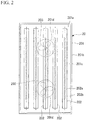
- the provisional fixer 20 is configured by attaching the infrared heater 202 and the blowing fan 203 for blowing the air to the print surface 101a of the web 101 to a provisional fixer main body 201 installed along the web 101.
- the provisional fixer main body 201 has a backboard portion 201a and a square frame-shaped side wall potion 201b disposed at the outer periphery portion of the backboard portion 201a.
- the provisional fixer main body 201 is formed in the shape of a concave cover that houses the infrared heater 202 at the inner side of the side wall portion 201b.
- the infrared heater 202 is formed in the shape of a rod and is arranged and installed in a plurality of rows at the inner side of the provisional fixer main body 201 so as to make the longitudinal direction thereof align with the flow direction of the web 101.
- the plurality of infrared heaters 202 is arranged, side by side and installed on a plane, which is substantially parallel with the print surface 101a of the web 101 passed through the provisional fixing treatment space 22.
- the number of infrared heaters 202 installed is not particularly limited.
- the infrared heater 202 may be installed in the up/down multistage manner, for example, in a direction extending in the horizontal direction.
- the shape of the infrared heater is not particularly limited and is not limited to the shape of a rod.
- the infrared heater 202 is configured by putting a filament 202a, which is heated by the application of an electric current to radiate infrared light, in an infrared light permeable holding tube 202b.
- the holding tube 202b is, for example, formed of a material with superior infrared light permeability such as quartz glass.
- the filament 202a is put in the holding tube 202b over the whole length thereof in the longitudinal direction.
- the material of the filament 202a for example, Kanthal line, tungsten, carbon, or the like can be used.
- the provisional fixer main body 201 is installed so that an opposite side (hereinafter, also called an opening side) of the backboard portion 201a faces the web 101 side through the inner space (the heater housing space 201c) surrounded by the side wall portion 201b.
- the provisional fixer 20 can irradiate infrared light radiated from the infrared heater 202 from the opening side of the provisional fixer main body 201 to the web 101.
- the provisional fixer main body 201 may be configured such that the inner surface of the heater housing space 201c is made as an infrared light reflective surface by means of the installation of a reflective plate or the like for reflecting infrared light.
- the provisional fixer main body 201 is formed of an infrared-light reflective material, whereby the inner surface of the heater housing space 201c may be an infrared light reflective surface.
- the blowing fan 203 is built in an air inlet hole 201d opened to the backboard portion 201a of the provisional fixer main body 201.
- the blowing fan 203 draws air outside the provisional fixer main body 201 into the provisional fixer main body 201 and blows air onto the web 101.
- the air blown by the blowing fan 203 is used for the drying removal (the removal and drying by the evaporation) of the carrier liquid absorbed into the web 101. Furthermore, it also effectively contributes to overheating prevention of the provisional fixer 20.
- the fan 23 and the blower 24 each function as an air flow forming device for providing an air flow from the lower end portion to the upper part in the provisional fixing treatment space 22 to exhaust a vapor which is evaporated from the web 101 by the irradiation of infrared light from the infrared heater 202 of the provisional fixer 20.
- the air flow fulfills the function of discharging the carrier liquid (the vapor of the carrier liquid) evaporated from the portion of the web 101 (an area (hereinafter, also called a provisional fixing area 101b) provided so as to follow the overall lengths of the infrared heater 202 of the provisional fixer 20, mainly in the longitudinal direction of the web 101) passing through the provisional fixing treatment space 22, from the provisional fixing treatment space 22.
- an area hereinafter, also called a provisional fixing area 101b
- the fan 23 is installed at the lower side of the provisional fixing treatment space 22 between the heat shielding plate 21 and the provisional fixer 20 to provide the air flow from the lower end portion thereof to the upper part in the provisional fixing treatment space 22 by the air blown to the upper part. That is, the fan 23 provides the air flow, which rises along the web 101 passing through the provisional fixing treatment space 22, in the provisional fixing treatment space 22.
- the fans 23 are each installed at both sides (both sides via the web 101 in the thickness direction of the web 101) via the web 101.
- the web 101 passes between a pair of fans 23 that is installed separately from each other at the lower side of the provisional fixing treatment space 22.
- Blower 24 is installed at the upper end of the provisional fixing treatment space 22.
- the blower 24 absorbs and exhausts the air in the provisional fixing treatment space 22, whereby airflow is formed from the lower end portion to the upper part in the provisional fixing treatment space 22.
- the toner fixing device and the electrophotographic printer according to the present invention are not limited to a configuration which adopts both of the fan 23 and the blower 24 as the air flow forming device for providing the air flow from the lower end portion to the upper part in the provisional fixing treatment space 22, may be a configuration which adopts only one of the fan 23 and the blower 24.
- the temperature of the air (air to be transported to the provisional fixing treatment space 22 by the fan 23, in the shown example) introduced into the provisional fixing treatment space 22 for providing the air flow in the provisional fixing treatment space 22 by the air flow forming device be, for example, 10 to 40°C.
- the air flow forming device in which provides an air flow rising in the provisional fixing treatment space 22 is described as a preferred embodiment of the present invention, an air flow forming device according to the present invention is not limited thereto.
- the air flow forming device may be of a type which provides the airflow in the direction (the direction along the surface of the web 101) along the web 101 in the provisional fixing treatment space 22 and, for example, may be a type of which provides an air flow dropping in the provisional fixing treatment space 22 or a type that provides a horizontal airflow.
- the airflow forming device has a configuration that provides the airflow rising in the provisional fixing treatment space 22 as described above, it is advantageous in smoothly discharging the vapor (the vapor rises upward from the provisional fixing area 101b of the web 101) of the carrier liquid, which is heated through infrared light irradiation from the infrared heater 202 of the provisional fixer 20 and is evolved from the web 101, from the provisional fixing treatment space 22.
- the airflow which is provided in the provisional fixing treatment space 22 by the fan 23 and the blower 24, comes in contact with the whole provisional fixing area 101b of the web 101 which passes through the provisional fixing treatment space 22.
- the web 101 which, is in a wet state by absorbing the carrier liquid, is effectively dried by the synergy effect of the drying performed by the irradiation of infrared light from the infrared heater 202 of the provisional fixer 20 and the drying performed by the airflow provided in the provisional fixing treatment space 22.
- the provisional fixing of the toner to the web 101 can be conducted in a short time.
- the vapor of the carrier liquid which is evaporated from the web 101 by the irradiation of infrared light, is smoothly exhausted from the provisional fixing treatment space 22 by means of the airflow provided in the provisional fixing treatment space 22 by the fan 23 and the blower 24.
- the vapor of the carrier liquid is smoothly exhausted from the provisional fixing treatment space 22 by means of the airflow provided in the provisional fixing treatment space 22 by the fan 23 and the blower 24.
- This also efficiently contributes to the drying of the web 101 in a short time.
- this is also effective in preventing contamination due to stagnation of the evaporation component of the residual toner.
- the drying of the web 101 by the irradiation of infrared light is performed in such a way that the infrared light is absorbed into the carrier liquid absorbed in the web 101, the carrier liquid is heated by the friction due to the inner vibration owing to the light energy in the carrier liquid, thereby the carrier liquid is evaporated and the web 101 is dried.
- the drying method of the web 101 by the irradiation of infrared light can conduct the drying removal of the carrier liquid and the drying of the web 101 effectively in a short time due to effective short time heating of the carrier liquid absorbed in the web 101, compared with the method of the related art, for example, the method of heating the web from the surface thereof by means of only jetting and spraying of the heating wind from a plurality of penetration holes provided on the plate-shaped heater body, as described in Japanese Unexamined Utility Model Application, First Publication No. 2-51353 .
- the downsizing of the provisional fixing portion 2 is also easily performed, which efficiently contributes to overall downsizing and space reductions in toner fixing device and the electrophotographic printer.
- the infrared heater 202 outputs infrared light with the maximum energy wave length of 1.2 to 2.5 ⁇ m.
- the infrared heater 202 it is preferable to use the infrared heater having, for example, the temperature of the filament 202a of 1400 to 2100°C due to the application of an electric current, the maximum energy wave length of 1.2 to 1.7 ⁇ m and the maximum energy density of 120kw/m 2 or the infrared heater having the temperature of the filament 202a of 950 to 1200°C due to the application of an electric current, the maximum energy wavelength of 2.0 to 2.5 ⁇ m and the maximum energy density of 100kw/m 2 .
- Such an infrared heater is effective for increasing the temperature of the object to be heated in a short time.
- the temperature of the web 101 can increase up to the temperature at which the carrier liquid can be dried and removed in a short time of about 1 to 3 seconds from the start of infrared light irradiation.
- an infrared heater is advantageous for the reduction in time of the drying removal of the carrier liquid and the drying of the web 101.
- the airflow provided by the blowing fan 203 of the provisional fixer 20 is also used for the drying removal of the carrier liquid absorbed into the web 101.
- the blast from the blowing fan 203 is heated by being passed through the heater housing space 201c at the inner side of the provisional fixer main body 201 of the provisional fixer 20 and is sprayed to the web 101 (the provisional fixing area101b).
- the air blown onto web 101 by the blowing fan 203 is extruded by the airflow provided in the provisional fixing treatment space 22 by the airflow forming device, and is discharged from the provisional fixing treatment space 22.
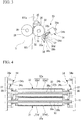
- the main fixing part 3 is configured by installing main fixing units 33, which press the web 101 by a pair of heating rollers 31 and 32 for a main fixing (i.e. a definitive fixing) while pinching the web therebetween, in the up/down multistage manner (six stages in FIG. 1 ).
- main fixing i.e. a definitive fixing
- the heating rollers 31 and 32 are both equipped with the infrared heater 39 and are heated by the infrared heater 39.
- the main fixing unit 33 includes a fixing side roller 31 which is a heating roller 31 fixed to the frame 11, a pressing roller 32 which is a heating roller 32 for pressing the web 101 against the fixing side roller 31, and a pressing mechanism 34 for pressing the pressing roller 32 against the fixing side roller 31.
- both ends of the pressing roller 32 in the axial center direction are rotatably attached to a bracket 36 which is rotatably attached to a rotation axis 35 provided on the frame 11.
- the pressing mechanism 34 is a driving cylinder device (hereinafter, when the pressing mechanism indicates the driving cylinder device, the pressing mechanism is also called the driving cylinder device) and has the following configuration. That is, the front end of a piston shaft 34c, which is protruded from the cylinder main body 34b connected to the frame 11 with a pin (a pin connected portion 34a), is rotatably connected to the bracket 36 via the pin 37.
- the protrusion of the piston shaft 34c from the cylinder main body 34b allows the pressing roller 32 to be pressed toward the fixing side roller 31. As a result, it is possible to press the web 101 with the pair of heating rollers 31 and 32 while pinching the web 101 therebetween.
- the main fixing unit 33 of the main fixing part 3 has a stopper 38 with which a contact piece 34d provided at the front end of the piston shaft 34c of the driving cylinder device 34 makes contact when the pressing roller 32 is pressed toward the fixing side roller 31.
- the stopper 38 is fixedly provided to the frame 11.
- the stopper 38 includes a fixing block 38a fixed to the frame 11, a bolt 38b which is threadably mounted on the fixing block 38a and can change the protrusion size from the fixing block 38a by the rotation operation, a fixing nut 38c that is threadably mounted on the bolt 38b and is tightly fastened to fix the bolt 38b to the fixing block 38a, and a head portion 38d which is formed at the front end protruded from the fixing block 38a of the bolt 38b and with which the contact piece 34d of the front end of the piston shaft 34c of the driving cylinder device 34 makes contact.
- the main fixing unit 33 by changing the screw fixing position of the bolt 38b with respect to the fixing block 38a to change the protrusion size of the bolt 38b from the fixing block 38a, it is possible to adjust the pressing force in which the pair of heating rollers 31 and 32 press the web 101 while pinching it therebetween.
- the state, in which the web 101 is pressed between the pair of heating rollers 31 and 32 while being pinched therebetween, can be released, which makes it possible to secure a distance capable of conducting an insertion and an extraction of the web 101 between the pair of heating rollers 31 and 32.
- the pressing roller 32 approaches the fixing side roller 31.
- the approach of the pressing roller 32 with respect to the fixing side roller 31 stops when contact piece 34d of the front end of the piston shaft 34c comes in contact with the stopper 38 (specifically, comes in contact with the head portion 38d of the bolt 38b).
- the movement of the pressing roller 32 due to the protrusion and the insertion of the piston shaft 34c of the driving cylinder device 34 (the rotation around the rotation shaft 35) is performed by maintaining the state in which the axial center of the pressing roller 32 and the axial center of the fixing side roller 31 are parallel to each other.
- the web 101 is pressed by pinching the web 101 from both sides in the width direction with the pair of heating rollers 31 and 32.
- the pressing roller 32 is configured such that the infrared heater 39 is put in an inner portion of an outer trunk 32a which is formed by covering the outer peripheral surface of a metallic cylinder 32a1 with a rubber covering layer 32a2.
- the infrared heater 39 has the same structure as the infrared heater 202 of the provisional fixer 20. That is, the infrared heater 39 has a rod-shaped structure in which the filament 39a, which is heated by the application of an electric current to radiate infrared light, is put in an infrared light permeable holding tube 39b.
- the filament 39a which can be used as the filament 202a of the infrared heater 202 of the provisional fixer 20 can be adopted.
- the filament 39a is put in the holding tube 39b for over the whole length in the longitudinal direction thereof.
- the infrared heater 39 is disposed on the center axis of the outer trunk 32a of the pressing roller 32 and is provided over the whole length of the outer trunk 32a in the axial center direction.
- the outer trunk 32a of the pressing roller 32 is heated by infrared light radiated from the filament 32b that is heated by the application of an electric current.
- the fixing side roller 31 of the main fixing unit 33 has the same structure as the pressing roller 32.
- reference numeral 31a shows an outer trunk of the fixing side roller 31.
- the outer trunk 31a is configured by covering the outer peripheral surface of a metallic cylinder 31a1 with a rubber covering layer 31a2.
- the fixing side roller 31 is configured by holding the infrared heater 39 within the outer trunk 31a.
- the infrared heater 39 is disposed on the axial center of the outer trunk 31a of the fixing side roller 31 and is provided over the whole length of the outer trunk 31a in the axial center direction.
- the outer trunk 31a of the fixing side roller 31 is heated by infrared light radiated from the filament which is heated by the application of an electric current.
- the main fixing unit 33 pinches and presses the web 101 by the pair of heating rollers 31 and 32 heated by the infrared heater 39, which securely enables the toner to be fixed to the web 101 by thermocompression bonding.
- a configuration that performs the thermocompression bonding with the pair of heating rollers 31 and 32 can satisfactorily secure the surface property in the print surface 101a of the web 101.
- the infrared heater 39 it is preferable for the infrared heater 39 to output infrared light with the maximum energy wavelength of 1.2 to 2.5 ⁇ m in the same manner as the infrared heater 202 of the provisional fixer 20.
- the infrared heater 39 it is preferable to use an infrared heater having, for example, the temperature of the filament 39a of 1400 to 2100°C by the application of an electric current, the maximum energy wave length of 1.2 to 1.7 ⁇ m and the maximum energy density of 120kw/m 2 or the infrared heater having the temperature of the filament 39a of 950 to 1200°C by the application of an electric current, the maximum energy wave length of 2.0 to 2.5 ⁇ m and the maximum energy density of 100kw/m 2 .
- infrared heaters are effective for increasing the temperature of the object to be heated in a short time, for example, when starting after the print preparation time or the restart after the temporary stop, the occurrence of paper damage can be reduced. This makes it possible to improve the production efficiency of the printed material.
- the main fixing part 3 includes a plurality of main fixing units 33, and goes the web 101 through the plurality of main fixing units 33 to conduct the main fixing (the definitive fixing) of the toner with respect to the web 101 by the thermocompression bonding in the respective main fixing units 33.
- the installation number of the main fixing unit 33 depending on the installation number or the print speed of the electrophotopraphic print unit 12 in the electrophotographic printer 10, it is possible to obtain a stable fixing state without non-uniformity.
- the heating and the pressurization of the web 101 are dividedly performed several times by the plurality of main fixing units 33, it is possible to easily and securely obtain a stable fixing state without non-uniformity.
- the toner fixing device 1 can also adjust the provisional fixing part 2 so as to be able to obtain a stable fixing state without non-uniformity depending on the installation number or the print speed of the electrophotopraphic print unit 12 in the electrophotographic printer 10 by adjusting the size (particularly, the size in the direction along the flow direction of the web 101) of the provisional fixer 20.
- the toner fixing device 1 has the composition in which the provisional fixing part 2 is provided at the upper side of the main fixing part 3 with the plurality of main fixing units 33 installed in the up/down multistage manner. For this reason, it is possible to freely assemble with the composition (the selection of the size of the provisional fixer 20 and/or the setting of the installation number of the main fixing unit 33) correspond to the printing conditions such as the number of print colors or the print speed in a certain space in the transverse direction of the printer. As a result, it is possible to provide the system with excellent quality and economic efficiency without any loss of print quality, production efficiency, installation space and equipment costs.
- the electrophotographic printer 10 performs the partial removal of the carrier liquid, which is absorbed into the inter-unit extension part 101c of the web 101 transported in the print device part 10A and the partial melting fixation of the toner, by the heating energy output from the infrared heater 17.
- the heating energy output from the infrared heater 17 With such composition, it is possible to effectively suppress the inverse transition phenomenon of the toner from the web 101 to the transfer roller 125 of the print unit 12, whereby the improvement and the advancement of the print quality can be realized.
- the web 101 of the state in which the removal of the carrier liquid and the fixing of the toner progress in a degree by the heating energy of the infrared heater 17 on the print device part 10A is supplied to the toner fixing device 1 by the transport movement.
- the web 101 of the state in which the removal of the carrier liquid and the fixing of the toner progress in a degree by the heating energy of the infrared heater 17 on the print device part 10A is supplied to the toner fixing device 1 by the transport movement.
- the electrophotographic printer 10 is configured to perform the drying removal of the carrier liquid from the web 101 and the fixing of the toner stage by stage by means of the print device part 10A (the infrared heater 17), the provisional fixing part 2 and the main fixing part 3. For this reason, there is an advantage in that it is possible to reduce the stress applied to the web 101 by the heating for the drying removal of the carrier liquid and the fixing of the toner, whereby obstacles such as paper wrinkles or paper stretches hardly occurs.
- the print device portion 10A has a configuration with the print units 12 in the up/down multistage manner, it is possible to assemble the print device portion 10A with a configuration (setting of the installation number of the print unit) correspond to the printing conditions such as the number of print colors or the print speed in a certain space in the transverse direction of the printer. For this reason, it is possible to construct the system with excellent quality and economical efficiency without any loss of print quality, production efficiency, installation space and equipment costs.
- the print device part is not limited to a configuration in which a plurality of print units with different print colors is provided for performing the multi-color printing, but, for example, can adopt a configuration including a plurality of print units with an identical print color, or a configuration in which the print colors of the overall print units are the same to perform a single color overlap printing or the like.
- the fixing auxiliary mechanism relating to the present invention is not limited thereto.
- a heater an electric heat heater
- an electric current application heating element such as an electric heat line, a warm wind heater or the like.
- the toner fixing device may have a configuration capable of conducting the drying removal of the carrier liquid absorbed into the web and the melting fixation of the toner to the web, and is not limited to the toner fixing device including the provisional fixing part and the main fixing part as in the above-mentioned embodiment, but can adopt various configurations.
- the electrophotographic printer according to the present invention may have a configuration which includes the provisional fixing part having the provisional fixer for performing the provisional fixing by the irradiation of infrared light, and the main fixing part for performing the main fixing (the definitive fixing) of the toner by pressing the web with the plurality of rollers including the heating roller for the main fixing (the definitive fixing) while pinching the web therebetween.
- the positional relationship of the provisional fixing part and the main fixing part, the installation number of the main fixing unit of the main fixing part, and the installation position are not limited to the configuration described in the above-mentioned embodiment.
- the main fixing unit it is also possible to adopt a configuration which includes the heating roller and a roller (a roller that is not provided with the heating function) other than the heating roller, as the roller for nipping the web.
- the heating roller provided on the main fixing part is not limited to a configuration equipped with the infrared heater as described in the above-mentioned embodiment.
- the present invention can also adopt a known heating roller for toner fixing in the wet type electrophotographic printer as the heat roller.
Landscapes
- Physics & Mathematics (AREA)
- General Physics & Mathematics (AREA)
- Fixing For Electrophotography (AREA)
- Wet Developing In Electrophotography (AREA)
- Color Electrophotography (AREA)
Claims (6)
- Elektrofotografischer Drucker (10), der umfasst:eine Vielzahl verbundener elektrofotografischer Druck-Einheiten (12), die Fotoleiter-Trommeln (121), auf denen Toner-Bilder hergestellt werden, sowie Übertragungs-Trommeln(125) aufweisen, die die Toner-Bilder der Fotoleiter-Trommeln (121) auf ein Aufzeichnungsmaterial (101) übertragen; undeinen Fixier-Hilfsmechanismus (17), der zwischen den elektrofotografischen Druck-Einheiten (12) in der Laufrichtung des Aufzeichnungsmaterials (101) vorhanden ist,dadurch gekennzeichnet, dass der Fixier-Hilfsmechanismus (17) aus einer Infrarot-Heizeinrichtung (17) besteht, die Infrarotlicht mit einer Wellenlänge maximaler Energie von 1,2 bis 2u µm ausgibt, wobei der Fixier-Hilfsmechanismus (17) Erhitzungs-Energie auf einen Toner und eine in dem Aufzeichnungsmaterial (101) absorbierte Trägerflüssigkeit aufbringt, um einen Teil der Trägerflüssigkeit durch Verdampfung zu entfernen, und einen Grad der Fixierung des Toners auf der Druck-Oberfläche (101a) des Aufzeichnungsmaterials (101) erhöht,einen Teilabschnitt (18) zur Steuerung von Energieausgabe, der die Ausgabe von Erhitzungs-Energie, die auf den Toner und die Trägerflüssigkeit des Aufzeichnungsmaterials (101) durch den Fixier-Hilfsmechanismus (17) aufgebracht wird, innerhalb eines Bereiches steuert, in dem der Grad der Fixierung des Toners auf dem Aufzeichnungsmaterial (101) durch die Erhitzungs-Energie die Bild-Übertragung auf das Aufzeichnungsmaterial (101) durch die elektrofotografische Druck-Einheit (12) der stromab liegenden Seite der Aufzeichnungsmaterial-Laufrichtung des Fixier-Hilfsmechanismus (17) nicht stört.
- Elektrofotografischer Drucker (10) nach Anspruch 1,
wobei die elektrofotografischen Druck-Einheiten (12) Stütz-Walzen (126) einschließen, die das Aufzeichnungsmaterial (101) an die Übertragungs-Walzen (125) drücken, und eine Vorspannung zwischen den Übertragungs-Walzen (125) und den Stütz-Walzen (126) der elektrofotografischen Druck-Einheiten (12) angelegt wird. - Elektrofotografischer Drucker (10) nach Anspruch 1,
wobei die elektrofotografischen Druck-Einheiten (12) nach oben/unten mehrstufig angeordnet sind. - Elektrofotografischer Drucker (10) nach Anspruch 1,
wobei die elektrofotografischen Druck-Einheiten (12) unterschiedliche Farben sind. - Elektrofotografischer Drucker (10) nach Anspruch 1, der des Weiteren eine Toner-Fixiervorrichtung (1), die trocknende Entfernung der Trägerflüssigkeit und Toner-Fixierung des Aufzeichnungsmaterials (101) durchführt, mit der der Aufdruck durch die elektrofotografische Druck-Einheit (12) abgeschlossen wird.
- Elektrofotografischer Drucker (10) nach Anspruch 5,
wobei die Toner-Fixiervorrichtung (1) ein Hilfs-Fixierteil (2) sowie ein Haupt-Fixierteil (3) einschließt und das Hilfs-Fixierteil (2) eine daran installierte Hilfs-Fixiereinrichtung (20) aufweist, die eine Infrarot-Heizeinrichtung (17) zum Bestrahlen der Druck-Oberfläche (101a) des in dem elektrofotografischen Drucker (10) transportierten Aufzeichnungsmaterials (101) mit Infrarotlicht einschließt, und das Haupt-Fixierteil (3) eine oder mehrere Haupt-Fixiereinheit/en (33) aufweist, die an der stromab liegenden Seite des Hilfs-Fixierteils (2) in der Aufzeichnungsmaterial-Laufrichtung vorhanden ist/sind und auf das Aufzeichnungsmaterial (101) drückt/drücken und dabei das Aufzeichnungsmaterial (101) dazwischen mit einer Vielzahl von Walzen (31, 32) einschließlich einer Heiz-Walze (31, 32) einklemmt/einklemmen.
Applications Claiming Priority (1)
| Application Number | Priority Date | Filing Date | Title |
|---|---|---|---|
| JP2009176742A JP5020293B2 (ja) | 2009-07-29 | 2009-07-29 | 電子写真印刷機 |
Publications (2)
| Publication Number | Publication Date |
|---|---|
| EP2284620A1 EP2284620A1 (de) | 2011-02-16 |
| EP2284620B1 true EP2284620B1 (de) | 2019-11-20 |
Family
ID=42831068
Family Applications (1)
| Application Number | Title | Priority Date | Filing Date |
|---|---|---|---|
| EP10170576.2A Active EP2284620B1 (de) | 2009-07-29 | 2010-07-23 | Elektrofotografischer Drucker |
Country Status (5)
| Country | Link |
|---|---|
| US (1) | US8452219B2 (de) |
| EP (1) | EP2284620B1 (de) |
| JP (1) | JP5020293B2 (de) |
| CN (1) | CN101989061B (de) |
| CA (1) | CA2709154C (de) |
Families Citing this family (13)
| Publication number | Priority date | Publication date | Assignee | Title |
|---|---|---|---|---|
| DE102012103343A1 (de) | 2012-04-17 | 2013-10-17 | Océ Printing Systems GmbH & Co. KG | Verfahren zum Betreiben eines Digitaldruckers unter Beaufschlagung eines Aufzeichnungsträgers mit Ionen sowie zugehöriger Digitaldrucker |
| JP2014063009A (ja) * | 2012-09-21 | 2014-04-10 | Brother Ind Ltd | 画像形成装置 |
| US9880501B2 (en) | 2013-08-29 | 2018-01-30 | Hp Indigo B.V. | Liquid electro-photographic printing |
| JP2015147858A (ja) * | 2014-02-06 | 2015-08-20 | 住友化学株式会社 | 樹脂組成物およびその成形体 |
| JP6289174B2 (ja) * | 2014-03-07 | 2018-03-07 | キヤノン株式会社 | 画像形成装置 |
| JP2015179115A (ja) * | 2014-03-18 | 2015-10-08 | 富士ゼロックス株式会社 | 定着装置及び画像形成装置 |
| JP2015184318A (ja) * | 2014-03-20 | 2015-10-22 | 富士ゼロックス株式会社 | 画像形成装置 |
| US9158244B1 (en) * | 2014-03-20 | 2015-10-13 | Fuji Xerox Co., Ltd. | Image forming apparatus using a developer containing a non-volatile oil |
| JP2016066000A (ja) | 2014-09-25 | 2016-04-28 | 富士ゼロックス株式会社 | 定着装置および画像形成装置 |
| DE102015100535A1 (de) * | 2015-01-15 | 2016-07-21 | Océ Printing Systems GmbH & Co. KG | Verfahren und Vorrichtung zum Drucken mit Temperaturverlauf zur optimalen Lösemittelpenetration |
| JP2016142955A (ja) * | 2015-02-03 | 2016-08-08 | 富士ゼロックス株式会社 | オイル除去装置、画像形成装置 |
| JP6726389B2 (ja) * | 2016-04-26 | 2020-07-22 | 富士ゼロックス株式会社 | 画像形成装置及びプログラム |
| CN114868087A (zh) * | 2019-12-29 | 2022-08-05 | 兰达公司 | 印刷方法和系统 |
Family Cites Families (25)
| Publication number | Priority date | Publication date | Assignee | Title |
|---|---|---|---|---|
| US3715225A (en) * | 1971-04-05 | 1973-02-06 | Varian Associates | Method for fixing of liquid toner developed electrographic images |
| GB2141072B (en) * | 1983-04-21 | 1986-08-20 | Arthur Roland Palmer | Ink drying apparatus |
| JPH01188884A (ja) * | 1988-01-22 | 1989-07-28 | Fuji Xerox Co Ltd | 画像形成装置 |
| JPH085482Y2 (ja) | 1988-07-20 | 1996-02-14 | 三菱製紙株式会社 | 電子写真用定着装置 |
| US5126781A (en) * | 1988-07-29 | 1992-06-30 | Brother Kogyo Kabushiki Kaisha | Image recording apparatus |
| JPH0251353U (de) | 1988-10-03 | 1990-04-11 | ||
| JPH0416863A (ja) * | 1990-05-10 | 1992-01-21 | Toshiba Corp | 液体現像剤および液体現像剤の製造方法 |
| JPH0445463A (ja) * | 1990-06-13 | 1992-02-14 | Toshiba Corp | 画像形成装置 |
| JPH06194969A (ja) * | 1992-12-24 | 1994-07-15 | Canon Inc | 画像形成装置 |
| JP2994943B2 (ja) * | 1994-02-22 | 1999-12-27 | 三菱重工業株式会社 | 液体現像液の定着方法及び装置 |
| JPH07311515A (ja) * | 1994-05-18 | 1995-11-28 | Fujitsu Ltd | シリアル型電子写真装置 |
| JPH09281753A (ja) * | 1996-04-10 | 1997-10-31 | Ricoh Co Ltd | トナー画像定着方法・トナー画像定着装置・画像形成ユニットおよび画像形成装置 |
| JPH10323974A (ja) * | 1997-03-25 | 1998-12-08 | Canon Inc | インクジェット記録方法と装置、及び該装置に用いられる定着発熱体 |
| KR100265736B1 (ko) * | 1997-12-08 | 2000-09-15 | 윤종용 | 전자사진방식프린터 |
| JP2003098864A (ja) * | 2001-09-25 | 2003-04-04 | Ricoh Co Ltd | 画像定着装置及び画像形成装置 |
| JP3765757B2 (ja) * | 2002-01-18 | 2006-04-12 | 富士通株式会社 | 液体現像剤用トナー及び液体現像剤、並びに、画像形成装置及び画像形成方法 |
| JP4574107B2 (ja) * | 2002-09-13 | 2010-11-04 | 株式会社ミヤコシ | 湿式電子写真印刷装置 |
| JP4452125B2 (ja) * | 2004-05-25 | 2010-04-21 | 株式会社ミヤコシ | 液体現像電子写真印刷機 |
| DE102004043920A1 (de) | 2004-09-10 | 2006-03-30 | OCé PRINTING SYSTEMS GMBH | Verfahren zur Modifikation von Eigenschaften von auf einem Bildträger aufgebrachten Tonerbildern bei einer elektrografischen Druck- oder Kopiereinrichtung |
| JP2007062268A (ja) * | 2005-09-01 | 2007-03-15 | Afuitsuto:Kk | 紫外線硬化インクを用いたインクジェットプリンター装置 |
| JP2008100501A (ja) * | 2006-09-19 | 2008-05-01 | Fujifilm Corp | インクジェット記録用インクセット及びインクジェット記録方法 |
| US7505722B2 (en) * | 2007-02-08 | 2009-03-17 | Xerox Corporation | Convective hot air impingement device with localized return paths |
| JP5181553B2 (ja) * | 2007-07-09 | 2013-04-10 | 株式会社リコー | 転写定着装置及び画像形成装置 |
| US7706731B2 (en) * | 2007-07-16 | 2010-04-27 | Xerox Corporation | Hybrid printing system |
| JP2009075552A (ja) * | 2007-08-24 | 2009-04-09 | Seiko Epson Corp | 現像装置、現像方法及び画像形成装置 |
-
2009
- 2009-07-29 JP JP2009176742A patent/JP5020293B2/ja not_active Expired - Fee Related
-
2010
- 2010-07-07 CA CA2709154A patent/CA2709154C/en not_active Expired - Fee Related
- 2010-07-23 EP EP10170576.2A patent/EP2284620B1/de active Active
- 2010-07-27 US US12/844,359 patent/US8452219B2/en not_active Expired - Fee Related
- 2010-07-27 CN CN201010239551.5A patent/CN101989061B/zh not_active Expired - Fee Related
Non-Patent Citations (1)
| Title |
|---|
| None * |
Also Published As
| Publication number | Publication date |
|---|---|
| US8452219B2 (en) | 2013-05-28 |
| CA2709154A1 (en) | 2011-01-29 |
| CN101989061B (zh) | 2015-10-14 |
| JP5020293B2 (ja) | 2012-09-05 |
| CN101989061A (zh) | 2011-03-23 |
| JP2011033650A (ja) | 2011-02-17 |
| CA2709154C (en) | 2018-04-03 |
| US20110026991A1 (en) | 2011-02-03 |
| EP2284620A1 (de) | 2011-02-16 |
Similar Documents
| Publication | Publication Date | Title |
|---|---|---|
| CA2709154C (en) | Electrophotographic printer | |
| JP5394034B2 (ja) | トナー定着装置、電子写真印刷機 | |
| CN114174931A (zh) | 图像形成装置 | |
| JP2016156858A (ja) | 定着装置と画像形成装置 | |
| US8712273B2 (en) | Fixing apparatus | |
| JP2014502365A (ja) | プリンタの蒸気処理の予熱 | |
| US10996625B2 (en) | Image forming apparatus and dew condensation countermeasurement system | |
| JP6149420B2 (ja) | 定着装置および画像形成装置 | |
| EP2621600B1 (de) | Vorrichtung und verfahren zur behandlung eines aufzeichnungssubstrates | |
| JP2005257853A (ja) | 画像形成装置 | |
| JP4523850B2 (ja) | 電子写真印刷装置の定着装置 | |
| US20240329576A1 (en) | Roller, fixing device, medium adjustment device, and image forming apparatus | |
| JP3668232B2 (ja) | トナー画像定着装置 | |
| JP2004163548A (ja) | 画像形成装置 | |
| JP4609276B2 (ja) | 定着装置及びこれを用いた画像形成装置 | |
| JP4121011B2 (ja) | 画像形成装置 | |
| JP2008145521A (ja) | 画像形成装置 | |
| HK1139212A (en) | Toner fixing apparatus and electrophotographic printing device | |
| JP5802600B2 (ja) | 定着装置及び画像形成装置 | |
| JP2020166078A (ja) | 紫外線照射前の予備加熱装置 | |
| JP2006227495A (ja) | 定着装置と画像形成装置 | |
| JP2001265140A (ja) | 定着装置 | |
| JP2004085906A (ja) | 画像形成装置 | |
| JP2004085908A (ja) | 画像形成装置 | |
| HK1130324B (en) | Toner fixing apparatus and electrophotographic printer |
Legal Events
| Date | Code | Title | Description |
|---|---|---|---|
| PUAI | Public reference made under article 153(3) epc to a published international application that has entered the european phase |
Free format text: ORIGINAL CODE: 0009012 |
|
| AK | Designated contracting states |
Kind code of ref document: A1 Designated state(s): AL AT BE BG CH CY CZ DE DK EE ES FI FR GB GR HR HU IE IS IT LI LT LU LV MC MK MT NL NO PL PT RO SE SI SK SM TR |
|
| AX | Request for extension of the european patent |
Extension state: BA ME RS |
|
| 17P | Request for examination filed |
Effective date: 20110708 |
|
| 17Q | First examination report despatched |
Effective date: 20160530 |
|
| GRAP | Despatch of communication of intention to grant a patent |
Free format text: ORIGINAL CODE: EPIDOSNIGR1 |
|
| STAA | Information on the status of an ep patent application or granted ep patent |
Free format text: STATUS: GRANT OF PATENT IS INTENDED |
|
| INTG | Intention to grant announced |
Effective date: 20190626 |
|
| GRAS | Grant fee paid |
Free format text: ORIGINAL CODE: EPIDOSNIGR3 |
|
| GRAA | (expected) grant |
Free format text: ORIGINAL CODE: 0009210 |
|
| STAA | Information on the status of an ep patent application or granted ep patent |
Free format text: STATUS: THE PATENT HAS BEEN GRANTED |
|
| AK | Designated contracting states |
Kind code of ref document: B1 Designated state(s): AL AT BE BG CH CY CZ DE DK EE ES FI FR GB GR HR HU IE IS IT LI LT LU LV MC MK MT NL NO PL PT RO SE SI SK SM TR |
|
| REG | Reference to a national code |
Ref country code: GB Ref legal event code: FG4D |
|
| REG | Reference to a national code |
Ref country code: CH Ref legal event code: EP |
|
| REG | Reference to a national code |
Ref country code: DE Ref legal event code: R096 Ref document number: 602010062010 Country of ref document: DE |
|
| REG | Reference to a national code |
Ref country code: IE Ref legal event code: FG4D |
|
| REG | Reference to a national code |
Ref country code: AT Ref legal event code: REF Ref document number: 1204859 Country of ref document: AT Kind code of ref document: T Effective date: 20191215 |
|
| REG | Reference to a national code |
Ref country code: NL Ref legal event code: FP |
|
| REG | Reference to a national code |
Ref country code: LT Ref legal event code: MG4D |
|
| PG25 | Lapsed in a contracting state [announced via postgrant information from national office to epo] |
Ref country code: GR Free format text: LAPSE BECAUSE OF FAILURE TO SUBMIT A TRANSLATION OF THE DESCRIPTION OR TO PAY THE FEE WITHIN THE PRESCRIBED TIME-LIMIT Effective date: 20200221 Ref country code: LV Free format text: LAPSE BECAUSE OF FAILURE TO SUBMIT A TRANSLATION OF THE DESCRIPTION OR TO PAY THE FEE WITHIN THE PRESCRIBED TIME-LIMIT Effective date: 20191120 Ref country code: SE Free format text: LAPSE BECAUSE OF FAILURE TO SUBMIT A TRANSLATION OF THE DESCRIPTION OR TO PAY THE FEE WITHIN THE PRESCRIBED TIME-LIMIT Effective date: 20191120 Ref country code: FI Free format text: LAPSE BECAUSE OF FAILURE TO SUBMIT A TRANSLATION OF THE DESCRIPTION OR TO PAY THE FEE WITHIN THE PRESCRIBED TIME-LIMIT Effective date: 20191120 Ref country code: LT Free format text: LAPSE BECAUSE OF FAILURE TO SUBMIT A TRANSLATION OF THE DESCRIPTION OR TO PAY THE FEE WITHIN THE PRESCRIBED TIME-LIMIT Effective date: 20191120 Ref country code: BG Free format text: LAPSE BECAUSE OF FAILURE TO SUBMIT A TRANSLATION OF THE DESCRIPTION OR TO PAY THE FEE WITHIN THE PRESCRIBED TIME-LIMIT Effective date: 20200220 Ref country code: NO Free format text: LAPSE BECAUSE OF FAILURE TO SUBMIT A TRANSLATION OF THE DESCRIPTION OR TO PAY THE FEE WITHIN THE PRESCRIBED TIME-LIMIT Effective date: 20200220 Ref country code: ES Free format text: LAPSE BECAUSE OF FAILURE TO SUBMIT A TRANSLATION OF THE DESCRIPTION OR TO PAY THE FEE WITHIN THE PRESCRIBED TIME-LIMIT Effective date: 20191120 |
|
| PG25 | Lapsed in a contracting state [announced via postgrant information from national office to epo] |
Ref country code: IS Free format text: LAPSE BECAUSE OF FAILURE TO SUBMIT A TRANSLATION OF THE DESCRIPTION OR TO PAY THE FEE WITHIN THE PRESCRIBED TIME-LIMIT Effective date: 20200320 Ref country code: HR Free format text: LAPSE BECAUSE OF FAILURE TO SUBMIT A TRANSLATION OF THE DESCRIPTION OR TO PAY THE FEE WITHIN THE PRESCRIBED TIME-LIMIT Effective date: 20191120 |
|
| PG25 | Lapsed in a contracting state [announced via postgrant information from national office to epo] |
Ref country code: AL Free format text: LAPSE BECAUSE OF FAILURE TO SUBMIT A TRANSLATION OF THE DESCRIPTION OR TO PAY THE FEE WITHIN THE PRESCRIBED TIME-LIMIT Effective date: 20191120 |
|
| PG25 | Lapsed in a contracting state [announced via postgrant information from national office to epo] |
Ref country code: DK Free format text: LAPSE BECAUSE OF FAILURE TO SUBMIT A TRANSLATION OF THE DESCRIPTION OR TO PAY THE FEE WITHIN THE PRESCRIBED TIME-LIMIT Effective date: 20191120 Ref country code: RO Free format text: LAPSE BECAUSE OF FAILURE TO SUBMIT A TRANSLATION OF THE DESCRIPTION OR TO PAY THE FEE WITHIN THE PRESCRIBED TIME-LIMIT Effective date: 20191120 Ref country code: CZ Free format text: LAPSE BECAUSE OF FAILURE TO SUBMIT A TRANSLATION OF THE DESCRIPTION OR TO PAY THE FEE WITHIN THE PRESCRIBED TIME-LIMIT Effective date: 20191120 Ref country code: EE Free format text: LAPSE BECAUSE OF FAILURE TO SUBMIT A TRANSLATION OF THE DESCRIPTION OR TO PAY THE FEE WITHIN THE PRESCRIBED TIME-LIMIT Effective date: 20191120 Ref country code: PT Free format text: LAPSE BECAUSE OF FAILURE TO SUBMIT A TRANSLATION OF THE DESCRIPTION OR TO PAY THE FEE WITHIN THE PRESCRIBED TIME-LIMIT Effective date: 20200412 |
|
| REG | Reference to a national code |
Ref country code: AT Ref legal event code: MK05 Ref document number: 1204859 Country of ref document: AT Kind code of ref document: T Effective date: 20191120 |
|
| REG | Reference to a national code |
Ref country code: DE Ref legal event code: R097 Ref document number: 602010062010 Country of ref document: DE |
|
| PG25 | Lapsed in a contracting state [announced via postgrant information from national office to epo] |
Ref country code: SK Free format text: LAPSE BECAUSE OF FAILURE TO SUBMIT A TRANSLATION OF THE DESCRIPTION OR TO PAY THE FEE WITHIN THE PRESCRIBED TIME-LIMIT Effective date: 20191120 Ref country code: SM Free format text: LAPSE BECAUSE OF FAILURE TO SUBMIT A TRANSLATION OF THE DESCRIPTION OR TO PAY THE FEE WITHIN THE PRESCRIBED TIME-LIMIT Effective date: 20191120 |
|
| PLBE | No opposition filed within time limit |
Free format text: ORIGINAL CODE: 0009261 |
|
| STAA | Information on the status of an ep patent application or granted ep patent |
Free format text: STATUS: NO OPPOSITION FILED WITHIN TIME LIMIT |
|
| 26N | No opposition filed |
Effective date: 20200821 |
|
| PG25 | Lapsed in a contracting state [announced via postgrant information from national office to epo] |
Ref country code: PL Free format text: LAPSE BECAUSE OF FAILURE TO SUBMIT A TRANSLATION OF THE DESCRIPTION OR TO PAY THE FEE WITHIN THE PRESCRIBED TIME-LIMIT Effective date: 20191120 Ref country code: AT Free format text: LAPSE BECAUSE OF FAILURE TO SUBMIT A TRANSLATION OF THE DESCRIPTION OR TO PAY THE FEE WITHIN THE PRESCRIBED TIME-LIMIT Effective date: 20191120 Ref country code: SI Free format text: LAPSE BECAUSE OF FAILURE TO SUBMIT A TRANSLATION OF THE DESCRIPTION OR TO PAY THE FEE WITHIN THE PRESCRIBED TIME-LIMIT Effective date: 20191120 |
|
| REG | Reference to a national code |
Ref country code: DE Ref legal event code: R119 Ref document number: 602010062010 Country of ref document: DE |
|
| PG25 | Lapsed in a contracting state [announced via postgrant information from national office to epo] |
Ref country code: MC Free format text: LAPSE BECAUSE OF FAILURE TO SUBMIT A TRANSLATION OF THE DESCRIPTION OR TO PAY THE FEE WITHIN THE PRESCRIBED TIME-LIMIT Effective date: 20191120 |
|
| REG | Reference to a national code |
Ref country code: CH Ref legal event code: PL |
|
| REG | Reference to a national code |
Ref country code: NL Ref legal event code: MM Effective date: 20200801 |
|
| GBPC | Gb: european patent ceased through non-payment of renewal fee |
Effective date: 20200723 |
|
| REG | Reference to a national code |
Ref country code: BE Ref legal event code: MM Effective date: 20200731 |
|
| PG25 | Lapsed in a contracting state [announced via postgrant information from national office to epo] |
Ref country code: CH Free format text: LAPSE BECAUSE OF NON-PAYMENT OF DUE FEES Effective date: 20200731 Ref country code: LI Free format text: LAPSE BECAUSE OF NON-PAYMENT OF DUE FEES Effective date: 20200731 Ref country code: LU Free format text: LAPSE BECAUSE OF NON-PAYMENT OF DUE FEES Effective date: 20200723 Ref country code: NL Free format text: LAPSE BECAUSE OF NON-PAYMENT OF DUE FEES Effective date: 20200801 Ref country code: GB Free format text: LAPSE BECAUSE OF NON-PAYMENT OF DUE FEES Effective date: 20200723 Ref country code: FR Free format text: LAPSE BECAUSE OF NON-PAYMENT OF DUE FEES Effective date: 20200731 |
|
| PG25 | Lapsed in a contracting state [announced via postgrant information from national office to epo] |
Ref country code: DE Free format text: LAPSE BECAUSE OF NON-PAYMENT OF DUE FEES Effective date: 20210202 Ref country code: BE Free format text: LAPSE BECAUSE OF NON-PAYMENT OF DUE FEES Effective date: 20200731 |
|
| PG25 | Lapsed in a contracting state [announced via postgrant information from national office to epo] |
Ref country code: IE Free format text: LAPSE BECAUSE OF NON-PAYMENT OF DUE FEES Effective date: 20200723 |
|
| PG25 | Lapsed in a contracting state [announced via postgrant information from national office to epo] |
Ref country code: IT Free format text: LAPSE BECAUSE OF NON-PAYMENT OF DUE FEES Effective date: 20200723 |
|
| PG25 | Lapsed in a contracting state [announced via postgrant information from national office to epo] |
Ref country code: TR Free format text: LAPSE BECAUSE OF FAILURE TO SUBMIT A TRANSLATION OF THE DESCRIPTION OR TO PAY THE FEE WITHIN THE PRESCRIBED TIME-LIMIT Effective date: 20191120 Ref country code: MT Free format text: LAPSE BECAUSE OF FAILURE TO SUBMIT A TRANSLATION OF THE DESCRIPTION OR TO PAY THE FEE WITHIN THE PRESCRIBED TIME-LIMIT Effective date: 20191120 Ref country code: CY Free format text: LAPSE BECAUSE OF FAILURE TO SUBMIT A TRANSLATION OF THE DESCRIPTION OR TO PAY THE FEE WITHIN THE PRESCRIBED TIME-LIMIT Effective date: 20191120 |
|
| PG25 | Lapsed in a contracting state [announced via postgrant information from national office to epo] |
Ref country code: MK Free format text: LAPSE BECAUSE OF FAILURE TO SUBMIT A TRANSLATION OF THE DESCRIPTION OR TO PAY THE FEE WITHIN THE PRESCRIBED TIME-LIMIT Effective date: 20191120 |