EP2284794B1 - Appareil de tomodensitometrie (ct) à rayons x et dispositif de traitement - Google Patents
Appareil de tomodensitometrie (ct) à rayons x et dispositif de traitement Download PDFInfo
- Publication number
- EP2284794B1 EP2284794B1 EP10193664.9A EP10193664A EP2284794B1 EP 2284794 B1 EP2284794 B1 EP 2284794B1 EP 10193664 A EP10193664 A EP 10193664A EP 2284794 B1 EP2284794 B1 EP 2284794B1
- Authority
- EP
- European Patent Office
- Prior art keywords
- image
- region
- contrast
- ray
- regions
- Prior art date
- Legal status (The legal status is an assumption and is not a legal conclusion. Google has not performed a legal analysis and makes no representation as to the accuracy of the status listed.)
- Ceased
Links
Images


Classifications
-
- A—HUMAN NECESSITIES
- A61—MEDICAL OR VETERINARY SCIENCE; HYGIENE
- A61B—DIAGNOSIS; SURGERY; IDENTIFICATION
- A61B5/00—Measuring for diagnostic purposes; Identification of persons
- A61B5/02—Detecting, measuring or recording for evaluating the cardiovascular system, e.g. pulse, heart rate, blood pressure or blood flow
- A61B5/02007—Evaluating blood vessel condition, e.g. elasticity, compliance
-
- A—HUMAN NECESSITIES
- A61—MEDICAL OR VETERINARY SCIENCE; HYGIENE
- A61B—DIAGNOSIS; SURGERY; IDENTIFICATION
- A61B6/00—Apparatus or devices for radiation diagnosis; Apparatus or devices for radiation diagnosis combined with radiation therapy equipment
- A61B6/48—Diagnostic techniques
- A61B6/481—Diagnostic techniques involving the use of contrast agents
-
- A—HUMAN NECESSITIES
- A61—MEDICAL OR VETERINARY SCIENCE; HYGIENE
- A61B—DIAGNOSIS; SURGERY; IDENTIFICATION
- A61B6/00—Apparatus or devices for radiation diagnosis; Apparatus or devices for radiation diagnosis combined with radiation therapy equipment
- A61B6/50—Apparatus or devices for radiation diagnosis; Apparatus or devices for radiation diagnosis combined with radiation therapy equipment specially adapted for specific body parts; specially adapted for specific clinical applications
- A61B6/504—Apparatus or devices for radiation diagnosis; Apparatus or devices for radiation diagnosis combined with radiation therapy equipment specially adapted for specific body parts; specially adapted for specific clinical applications for diagnosis of blood vessels, e.g. by angiography
-
- G—PHYSICS
- G06—COMPUTING OR CALCULATING; COUNTING
- G06T—IMAGE DATA PROCESSING OR GENERATION, IN GENERAL
- G06T12/00—Tomographic reconstruction from projections
- G06T12/30—Image post-processing, e.g. metal artefact correction
-
- G—PHYSICS
- G06—COMPUTING OR CALCULATING; COUNTING
- G06T—IMAGE DATA PROCESSING OR GENERATION, IN GENERAL
- G06T5/00—Image enhancement or restoration
- G06T5/20—Image enhancement or restoration using local operators
-
- G—PHYSICS
- G06—COMPUTING OR CALCULATING; COUNTING
- G06T—IMAGE DATA PROCESSING OR GENERATION, IN GENERAL
- G06T5/00—Image enhancement or restoration
- G06T5/73—Deblurring; Sharpening
- G06T5/75—Unsharp masking
-
- G—PHYSICS
- G06—COMPUTING OR CALCULATING; COUNTING
- G06T—IMAGE DATA PROCESSING OR GENERATION, IN GENERAL
- G06T7/00—Image analysis
- G06T7/0002—Inspection of images, e.g. flaw detection
- G06T7/0012—Biomedical image inspection
-
- G—PHYSICS
- G06—COMPUTING OR CALCULATING; COUNTING
- G06T—IMAGE DATA PROCESSING OR GENERATION, IN GENERAL
- G06T7/00—Image analysis
- G06T7/10—Segmentation; Edge detection
- G06T7/11—Region-based segmentation
-
- G—PHYSICS
- G06—COMPUTING OR CALCULATING; COUNTING
- G06T—IMAGE DATA PROCESSING OR GENERATION, IN GENERAL
- G06T7/00—Image analysis
- G06T7/40—Analysis of texture
-
- A—HUMAN NECESSITIES
- A61—MEDICAL OR VETERINARY SCIENCE; HYGIENE
- A61B—DIAGNOSIS; SURGERY; IDENTIFICATION
- A61B6/00—Apparatus or devices for radiation diagnosis; Apparatus or devices for radiation diagnosis combined with radiation therapy equipment
- A61B6/02—Arrangements for diagnosis sequentially in different planes; Stereoscopic radiation diagnosis
- A61B6/03—Computed tomography [CT]
- A61B6/032—Transmission computed tomography [CT]
-
- G—PHYSICS
- G06—COMPUTING OR CALCULATING; COUNTING
- G06T—IMAGE DATA PROCESSING OR GENERATION, IN GENERAL
- G06T2207/00—Indexing scheme for image analysis or image enhancement
- G06T2207/30—Subject of image; Context of image processing
- G06T2207/30004—Biomedical image processing
-
- G—PHYSICS
- G06—COMPUTING OR CALCULATING; COUNTING
- G06T—IMAGE DATA PROCESSING OR GENERATION, IN GENERAL
- G06T2211/00—Image generation
- G06T2211/40—Computed tomography
- G06T2211/404—Angiography
Definitions
- the present invention relates to an X-ray CT apparatus and an image processing apparatus which generate an image within a patient, on the basis of projection data obtained by irradiating the patient with X-rays.
- the multislice X-ray CT apparatus is a scanner including an X-ray source which irradiates the patient with fan beam X-rays having a spread width in a slice direction (the lengthwise direction of a patient couch), and a two-dimensional detector of a structure in which a plurality of detection element rows (of 4 rows, 8 rows, 16 rows, or the like) are arrayed in the slice direction, wherein the X-rays are moved by multiscan or helical scan.
- the multislice X-ray CT apparatus can obtain volume data over a wider range within the patient, at a higher precision and in a shorter time.
- VAN STRATEN MARCEL ET AL "Removal of arterial wall calcifications in CT angiography by local subtraction”
- MEDICAL PHYSICS, AIP, MELVILLE, NY US LNKD- DOI: 10.11181 1.1567271, vol. 30, no. 5, 1 May 2003 (2003-05-01), pages 761-770, XP012012060
- ISSN: 0094-2405 describes a subtraction processing that is focussed on a high-contrast component.
- KIM DO-YEON ET AL "Computerized quantification of carotid artery stenosis using MRA axial images.”
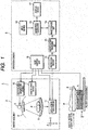
- FIG. 1 is a block diagram of an X-ray CT apparatus according to the first embodiment.
- the X-ray CT apparatus 1 includes a gantry 2 which is configured in order to acquire projection data on a patient, a patient couch 3 which serves to carry and move the patient P, and an operation console which serves to perform inputting and image display for operating the X-ray CT apparatus 1.
- the gantry 1 has an X-ray tube 5 and an X-ray detector 6.
- the X-ray tube 5 and the X-ray detector,6 are mounted on a ring-shaped rotation frame 8 which is driven to rotate by a gantry drive device 7.
- the patient couch 3 includes a top 8 on which the patient is placed, and a top drive device 9 which serves to move the top 8.
- the rotation frame 8 has an opening at its central part. The patient P placed on the top 8 is inserted into the opening.
- the axis of the center of the rotation of the rotation frame 8 is defined by a Z-axis (the axis of a slice direction), and planes orthogonal to the Z-axis are defined by two orthogonal axes of X and Y.
- a tube voltage is applied between the cathode and anode of the X-ray tube 5 by a high-voltage generator 10.
- a filament current is fed from the high-voltage generator 10 to the filament of the X-ray tube 5.
- X-rays are generated by the application of the tube voltage and the feed of the filament current.
- a unidimensional array type detector or a two-dimensional array type detector (also termed "multislice type detector") is adopted as the X-ray detector 6.
- An X-ray detection element has a light receiving face which is, for example, 0.5 mm x 0.5 mm square.
- the X-ray detection elements numbering, for example, 916 are arrayed in a channel direction. Such arrays numbering, for example, 40 are juxtaposed in the slice direction, thereby to form the two-dimensional array type detector.
- a detector formed of the single array is the unidimensional array type detector.
- a data acquisition system 11 is generally called “DAS” (Data Acquisition System).
- DAS Data Acquisition System
- the data acquisition system 11 converts a signal outputted from the detector 6 every channel, into a voltage signal, and it amplifies the voltage signal and further converts this signal into a digital signal.
- Data (raw data) after the conversion are supplied to the operation console 4 outside the gantry.
- the preprocessing unit 12 of the operation console 4 subjects the data (raw data) outputted from the data acquisition system 11, to the correction processes of a sensitivity correction etc., so as to output the projection data.
- the projection data are sent to a reconstruction processing unit 13.
- the reconstruction processing unit 13 reconstructs image data on the basis of the projection data acquired by, for example, helical scan or/and volume scan using cone beam X-rays, and it stores the image data in an image storage unit 14.
- An image processing unit 15 generates a display image on the basis of the image data stored in the image storage unit 14.
- the settings of conditions for displaying the image, the setting of a region of interest, etc. are performed on the basis of inputs to an input device 16 by an operator. The details of the image processing unit will be explained later.
- a display device 17 displays the image generated by the image processing unit 15.
- the scan control unit 18 of the operation console 4 controls the high-voltage generation device 10, gantry drive device 7, data acquisition system 11 and top drive device 9 so that the scan such as helical scan may be performed on the basis of the inputs of the operator.
- the operation console 4 may be configured of dedicated hardware, or the same functions may well be incarnated by software by employing a computer.
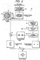
- FIG. 2 is a diagram for explaining the configuration of the image processing unit 15 in FIG. 1 .
- (A) in FIG. 2 is a model diagram' of a blood-vessel sectional structure which is one example of a subject for image processing.
- the sectional structure contains a vascular wall P1, a stent P2, a contrast medium (blood flow part) P3, and lipide P4.
- a vascular wall P1 vascular wall
- stent P2 a contrast medium (blood flow part) P3
- lipide P4 lipide
- the image processing unit 15 includes a region-of-interest setting/image extraction portion 19, a high-contrast extraction portion 20, a convolution portion 21, a CT number scaling portion 22, a subtractor 23, and an adder 24.
- the region-of-interest setting/image extraction portion 19 sets the region of interest on the basis of the input to the input device 16, and it extracts the image data of the region of interest from the image storage unit 14 and outputs the extracted image data.
- (B) in FIG. 2 represents the image of the region of interest as extracted by the region-of-interest setting/image extraction portion 19.
- the high-contrast extraction portion 20 extracts a high-contrast region of very high X-ray attenuation coefficient, that is, a group of pixels having very high CT numbers, from the image of the region of interest as extracted by the extraction portion 19.
- high-contrast substances there are metallic instruments such as the stent which is embedded in the patient for the purpose of medical care, calcified calcium, and so forth.
- a subject to be chiefly handled is not the stent or the like, but it is the contrast medium.
- the contrast medium which has a CT number between those of the stent and the vascular wall is selectively used.
- a binarized image is obtained in such a way that the difference between the value of a noted pixel and the mean value of the values of a plurality of pixels around the noted pixel is evaluated, thereby to obtain the differential image of the inputted image, and that the differential image is subjected to a threshold value process by employing a threshold value which corresponds to the peripheral edge of the stent.
- the binarized image becomes an image in which pixel values differ between a part where the high-contrast substance will exist and the other part. That is, the binarized image becomes an image which contains the information of positions where the high-contrast substance will exist (hereinbelow, termed "high-contrast position image").
- (C) in FIG. 2 represents the high-contrast position image.
- the high-contrast position image can be easily obtained by a comparatively small number of arithmetic processes.
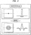
- the convolution portion 21 subjects the high-contrast position image to the convolution calculation of a point spread function (PSF) peculiar to the pertinent X-ray computer-tomographic apparatus.
- PSF point spread function
- the PSF is also called “transfer function” or “unsharpness function” as a function which defines an unsharpness characteristic peculiar to the apparatus.
- the PSF is obtained as the data of a two-dimensional image (unsharp image) concerning a wire phantom as has been obtained in such a way that the wire phantom which is more minute than the detector pitch (resolution limit) of the detector 6, for example, 0.5 mm and which has a diameter (0.05 mm) of, for example, 1/10 of the detector pitch is scanned, and that the two-dimensional image is reconstructed from the projection data of the scan.
- An image which is reconstructed from data acquired by scanning the high-contrast subject singly, that is, an image which contains the high-contrast subject and unsharpness appearing in the surroundings thereof, is obtained by convoluting the PSF into the high-contrast position image.
- the CT number scaling portion 22 normalizes (scales) the image (unsharp image) outputted from the convolution portion 21, in accordance with a value which is not unique as a CT number, here, a CT number which is standard for the contrast medium.
- the normalization process is the level adjustment process of pixel values for a subtraction process to be explained below.
- (D) in FIG. 2 represents an image which is outputted from the CT number scaling portion 22 (hereinbelow, termed "high-contrast image").
- the subtractor 23 executes the subtraction process, and obtains the difference image between the image of the region of interest and the high-contrast image.
- the low-contrast image is an image which represents a substance of low attenuation coefficient.
- (E) in FIG. 2 represents the-low-contrast image.
- the adder 24 adds the high-contrast position image to the low-contrast image, thereby to add the position information of the high-contrast substance.
- (F) in FIG. 2 represents the resulting output image.
- the output image is such that the position information of the high-contrast substance has been added to the image in which the unsharpness (artifact) ascribable to the high-contrast substance has been relieved from the original image of the region of interest, and it is displayed on the display device 17 via the processing of the succeeding stage.
- the lipide in the surroundings of the high-contrast substance as has been difficult of identification under the influence of the unsharpness in the original image can be favorably observed.
- the unsharp components which appear in the surroundings of the high-contrast substance can be relieved, so that substances surrounding the high-contrast substance can be favorably observed.
- the stent or calcification exists in a fine blood vessel having a diameter of 3 mm to 5 mm, such as the coronary artery of the heart, it is possible to favorably observe the vascular wall, the accumulated state of the lipide, the state of the contrast medium, etc. in the surroundings of the stent or calcification.
- the first embodiment may well be variously modified and carried out.
- the high-contrast position image has been added in the embodiment, only the low-contrast image may well be displayed without executing the addition. It is also allowed to superpose and display marks of different color as indicate the positions of the high-contrast substance.
- the embodiment may well be carried out as a medical image processing apparatus which displays an image on the basis of the projection data, a CT image or the like outputted from the X-ray CT apparatus.
- the processing of the two-dimensional image has been described in the embodiment, the processing of a three-dimensional image may well be executed by subjecting a plurality of two-dimensional images to the above processing.
- the pixel values of the image are the CT numbers
- any values other than the CT numbers may well be used as long as they represent X-ray attenuation coefficients.
- the high-contrast position image has been obtained by the differentiation/binarization process in the embodiment, it is also allowed to employ a method wherein a high-contrast position image is obtained by inversely convoluting a transfer function representative of unsharpness ascribable to a high-contrast substance, into an image, a method wherein the information items of the position and shape of a stent are stored beforehand, so as to obtain positional information on the basis of the stored information items, or the like.
- the second embodiment consists in that similar substances in an image are automatically classified by a clustering process in order to facilitate identifying the similar substances. It is known under ideal conditions that a plaque or lipide exhibits a CT number of -100 to 50, that a vascular wall exhibits a CT number of 50 to 129, and that a contrast medium contained in a blood flow exhibits a CT number of 130 to 350. In an actual examination, however, the CT numbers fluctuate under the influences of the body build of a patient, beam hardening, a reconstruction function, the sizes of the substances, the states of substances outside a region of interest, the concentration of the contrast medium, etc.
- a.region A corresponding chiefly to the plaque, a region B corresponding chiefly to the vascular wall, and a region C corresponding chiefly to the contrast medium are extracted from a low-contrast image at a high precision.
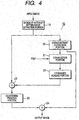
- FIG. 4 is a block diagram of an X-ray CT apparatus 1 according to the second embodiment.
- a clustering process portion 25 is located between a subtractor 23 and an adder 24.
- the clustering process portion 25 finds a plurality of predetermined regions on the basis of CT numbers, and it executes the conversion processing of the CT numbers so that the individual regions may be indicated at or in the same intensity or color.
- the CT numbers are divided into those of three regions will be described in this embodiment, but the number of regions may well be another number. Besides, the number of regions may well be made alterable in accordance with the input of an operator.
- FIG. 5 is a block diagram of the clustering process portion 25.
- the clustering process portion 25 includes a histogram generation part 26, a region determination part 27, and a CT number conversion part 28.
- the histogram generation portion 26 obtains the histogram of the inputted low-contrast image.
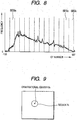
- the histogram represents the frequency distribution of pixel appearances at the respective CT numbers.
- the CT numbers are distributed in the range between -100 and 537.
- the region determination part 27 extracts, for example, three regions A, B and C from the low-contrast image.
- the region A corresponds chiefly to the plaque
- the region B corresponds chiefly to the vascular wall.
- the region C corresponds chiefly to the contrast medium.
- FIG. 7 shows the procedure of a process in which the three regions A, B and C are extracted from the low-contrast image by the region determination part 27.
- the vascular wall region B is extracted from the low-contrast image (S11).
- a plurality of trace lines are set so as to be radial from substantially the center of a blood vessel designated by the operator.
- CT numbers are traced along the respective trace lines. Positions at which the fluctuations of the CT numbers are comparatively large, that is, two positions which exhibit differential values exceeding a predetermined value, are specified as the inner point and outer point of the vascular wall.
- the plaque region A is extracted from the low-contrast image (S12).
- a group of pixels which have CT numbers lower than those of the vascular wall inside the vascular wall, are extracted as the plaque region A.
- the region C of the contrast medium is extracted (S13 - S19).
- the range in which the CT numbers are distributed on the histogram (in FIG. 6 , the range of from -100 to 537) is divided into N segments SEG 1 - SEG N by the k-means method (S13).
- the segment of the highest CT number is set as SEG 1 .
- "N” is set to be double or triple the number n of the regions which are to be finally classified.
- "m” denotes a processing variable. The variable "m” is initialized to "1".
- a region candidate R 1 corresponding to the segment SEG 1 is extracted from the low-contrast image (S14).
- the region R 1 is extracted from the low-contrast image by setting the lowest value of the segment SEG 1 as a threshold value.
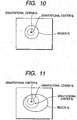
- the gravitational center position B 1 of the extracted region candidate R 1 is computed (S15).
- the variable m is incremented one (S17).
- CT min seg m ⁇ CT max/2 is judged as a stop condition for preventing diffusion.
- CT min seg m denotes the minimum number of the segment m
- CT max/2 denotes the maximum CT number of the low-contrast image.
- step S18 results in "No”
- step S19 is executed.
- step S18 results in "Yes”
- the extraction process returns to the step S14.
- a region candidate R 2 corresponding to the segment SEG 1 and segment SEG 2 is extracted from the low-contrast image (S14).
- the region candidate R 2 is extracted from the low-contrast image by setting the lowest value of the segment SEG 2 as a threshold value.
- the gravitational center position B 2 of the extracted region candidate R 2 is computed (S15).
- the distance D 2 between the gravitational center position B 2 of the region candidate R 2 and the gravitational center position B 1 of the last region candidate R 1 is computed, and it is compared with a predetermined threshold value "Th" (S16).
- the processing of the steps S14 - S18 is looped until the displacement magnitude D of the gravitational center position exceeds the threshold value Th. That is, the region candidate R is expanded little by little in accordance with the increment of the variable m . As the region candidate R is expanded, the gravitational center B is displaced. When a subject for the extraction is the same, the displacement magnitude of the gravitational center B is comparatively small. When the subject for the extraction has been expanded so as to contain another substance, the displacement magnitude of the gravitational center B becomes comparatively large. More specifically, when the subject for the extraction is the contrast medium, the gravitational center position does not change very much in spite of the expansion of the region candidate R. However, when the vascular wall or the like has been added to the subject for the extraction, the region candidate R rapidly becomes large, and also the gravitational center position changes greatly. A segment in which the gravitational center position changes greatly, is searched for.
- the last region candidate R 2 is specified as the region C of the contrast medium (S19). That is, the largest region candidate R 2 in which the displacement magnitude of the gravitational center is less than the threshold value Th is selected as the specified region C.
- the region C of the contrast medium can be extracted at a high precision without being-considerably influenced by the factors of the CT number fluctuations.
- the region B of the vascular wall can be similarly extracted at a high precision without being considerably influenced by the factors of the CT number fluctuations, by taking note of the CT number change.
- the region A of the plaque can be similarly extracted at a high precision without being considerably influenced by the factors of the CT number fluctuations, by setting the condition of the CT numbers inside the vascular wall.
- the region determination part 27 may well classify the histogram into three regions by employing the k-mean method.
- a threshold value "Th" for determining the individual regions is calculated by the k-mean method so that the variance values of CT numbers in the respective regions may become equal.
- the respective regions are determined so that the variance values of the CT numbers in the respective regions may become equal, whereby substances of high similarities are easily included in the same region.
- FIG. 6 represents the example in which the regions are divided by this embodiment, and the CT numbers of -100 to 537 are classified into the three regions. Pixels having the CT numbers in the range of the region A correspond chiefly to the part of the lipide. Pixels having the CT numbers in the range of the region B correspond chiefly to the part of the vascular wall. Pixels having the CT numbers in the range of the region C correspond chiefly to the part of the plaque.
- the CT number conversion part 28 replaces the CT numbers of the pixels respectively included in the three regions extracted or classified by the region determination part 27, with the characteristic values of the respective regions as have been set beforehand.
- the same regional part is displayed at or in the same intensity or color on a display image, and the respective regions are displayed in graspable aspects.
- the image in which the regions are divided in accordance with the CT numbers is displayed, and it is therefore possible to provide an image from which different substances such as a tissue, the lipide and the contrast medium within the patient can be favorably grasped.
- the threshold values for determining the regions are automatically found on the basis of the histogram, it is possible to provide an image in which the regions are favorably classified even in the existence of the fluctuations of CT numbers.
- the low-contrast image is subjected to the clustering process after the unsharp components (artifact components) appearing in the surroundings of the high-contrast substances have been relieved, so that substances in the surroundings of the high-contrast substances can be favorably observed.
- unsharp components artifact components
- the low-contrast image is subjected to the clustering process after the unsharp components (artifact components) appearing in the surroundings of the high-contrast substances have been relieved, so that substances in the surroundings of the high-contrast substances can be favorably observed.
- a stent or calcification exists in a fine blood vessel having a diameter of 3 mm to 5 mm, such as the coronary artery of the heart, it is possible to favorably observe the vascular wall, the accumulated state of the lipide, the state of the contrast medium, etc. in the surroundings of the stent or calcification.
- the clustering process is executed for the image in which the high-contrast substances are not contained, and the information items of the high-contrast substances are thereafter added, so that the regional division of a part having low CT numbers can be favorably made.
- the invention is not restricted to the embodiments, but it can be concretized by modifying the constituents within a scope not departing from the purport thereof, at the stage of performance.
- various inventions can be formed by appropriately combining two or more of the constituents disclosed in the embodiments.
- several constituents may well be omitted from all the constituents indicated in each embodiment.
- the constituents in the different embodiments may well be appropriately combined.
- the threshold values have been calculated by the k-mean method in the above embodiment, they may well be calculated by employing another clustering technique such as the group mean method or the Ward method.
- the clustering process has been executed for the image in which the high-contrast substance and the unsharpness in the surroundings thereof have been eliminated, but a display image may well be generated by executing a clustering process directly for the original image of the region of interest, without executing the such a process of the embodiment.
- the high-contrast position image has been added in each embodiment, only the low-contrast image may well be displayed without the addition. Besides, a mark of different color as indicates the position of the high-contrast substance may well be displayed in superposition.
- the embodiment may well be carried out as a medical image processing apparatus which displays an image on the basis of the projection data, a CT image or the like outputted from the X-ray CT apparatus.
- the processing of the two-dimensional image has been described in the above embodiment, the processing of a three-dimensional image may well be executed by subjecting a plurality of two-dimensional images to the above processing.
- the case where the pixel values of the image are the CT numbers has been described in the above embodiment, but any values other than the CT numbers may well be used as long as they represent X-ray attenuation coefficients.
Landscapes
- Engineering & Computer Science (AREA)
- Health & Medical Sciences (AREA)
- Life Sciences & Earth Sciences (AREA)
- Physics & Mathematics (AREA)
- Medical Informatics (AREA)
- General Physics & Mathematics (AREA)
- Theoretical Computer Science (AREA)
- General Health & Medical Sciences (AREA)
- Computer Vision & Pattern Recognition (AREA)
- Nuclear Medicine, Radiotherapy & Molecular Imaging (AREA)
- Veterinary Medicine (AREA)
- Pathology (AREA)
- Radiology & Medical Imaging (AREA)
- Biomedical Technology (AREA)
- Heart & Thoracic Surgery (AREA)
- Molecular Biology (AREA)
- Surgery (AREA)
- Animal Behavior & Ethology (AREA)
- Biophysics (AREA)
- Public Health (AREA)
- High Energy & Nuclear Physics (AREA)
- Vascular Medicine (AREA)
- Optics & Photonics (AREA)
- Cardiology (AREA)
- Physiology (AREA)
- Quality & Reliability (AREA)
- Dentistry (AREA)
- Oral & Maxillofacial Surgery (AREA)
- Apparatus For Radiation Diagnosis (AREA)
- Image Processing (AREA)
Claims (7)
- Appareil de tomodensitométrie (CT) à rayons X permettant d'acquérir des données de projection d'un patient et de reconstruire une image radiographique du patient sur la base des données de projection acquises, l'appareil de tomodensitométrie à rayons X comprenant:une unité (20) configurée de façon à extraire une région à haut contraste (C) à coefficient d'atténuation des rayons X relativement élevé hors de l'image radiographique (B);une unité (20, 21, 22) configurée de façon à générer une image floue (D) concernant la région à haut contraste, sur la base d'une position de la région à haut contraste extraite (C) et d'une fonction d'étalement de point spécifique à l'appareil de tomodensitométrie à rayons X;une unité (23) configurée de façon à soustraire l'image floue (D) de l'image mentionnée en premier lieu afin de générer une image à faible contraste (E) concernant une région à faible contraste à coefficient d'atténuation des rayons X relativement faible;une unité de classification qui classifie l'image à faible contraste (E) en une pluralité de régions selon des nombres CT, l'unité de classification comprenant une partie de génération d'histogrammes (26) configurée de façon à obtenir l'histogramme de l'image à faible contraste (E), l'histogramme représentant une distribution de fréquence d'apparitions de pixels aux nombres CT respectifs, et une partie de détermination de régions (27), la partie de détermination de régions (27) comprenant:une unité configurée de façon à extraire une pluralité de régions de différentes grandeurs hors de l'image à faible contraste sur la base d'une pluralité de valeurs de seuil,
en divisant une plage dans laquelle les nombres CT sont distribués sur l'histogramme en N segments (SEG1 - SEGN), dans lequel le segment avec le plus haut nombre CT est fixé comme un premier segment (SEG1) et "N" est fixé à un entier qui dépasse le nombre n de régions qui doivent être finalement classifiées, et
en extrayant des régions candidates (R1, R2) correspondant à des segments respectifs (SEG1) hors de l'image à faible contraste (E), une région respective (R1) étant extraite de l'image à faible contraste (E) en posant la plus basse valeur du segment respectif (SEG1, SEG2) comme une valeur de seuil;une unité configurée de façon à calculer des centres de gravité respectifs de la pluralité de régions extraites; etune unité configurée de façon à sélectionner une région spécifiée correspondant à un sujet pour l'extraction, à partir de la pluralité de régions extraites sur la base de distances entre les centres de gravité de la région et d'une région précédente, et une comparaison avec une valeur de seuil prédéterminée (Th), recherchant ainsi un segment dans lequel une position du centre de gravité change fortement, et spécifiant la dernière région avant de dépasser la valeur de seuil prédéterminée (Th) comme étant la région spécifiée à classifier; etune unité (28) qui remplace des valeurs de pixels de l'image à faible contraste par des valeurs qui sont respectivement spécifiques à la pluralité de régions classifiées. - Appareil de tomodensitométrie à rayons X selon la revendication 1, comprenant en outre une unité (24) configurée de façon à ajouter une image de position de la région à haut contraste (C) extraite à l'image à faible contraste (E) remplacée.
- Appareil de tomodensitométrie à rayons X selon la revendication 1 ou 2, dans lequel une région dans laquelle un lipide est prédominant, une région dans laquelle une paroi vasculaire est prédominante, et une région dans laquelle un fluide de contraste est prédominant, sont incluses dans la pluralité de régions classifiées.
- Appareil de tomodensitométrie à rayons X selon l'une quelconque des revendications précédentes, dans lequel la pluralité de valeurs de seuil est déterminée sur la base d'une distribution de fréquence d'apparitions de pixels de nombres CT respectifs concernant l'image.
- Appareil de tomodensitométrie à rayons X selon l'une quelconque des revendications précédentes, dans lequel "N" est posé de façon à être le double ou le triple du nombre n de régions qui doivent être finalement classifiées.
- Appareil de tomodensitométrie à rayons X selon l'une quelconque des revendications précédentes, dans lequel l'unité configurée de façon à extraire une pluralité de régions de différentes grandeurs est en outre configurée de façon à calculer les valeurs de seuil par la méthode des k-moyennes ou en employant une autre technique de partitionnement telle que la méthode de la moyenne de groupe ou la méthode de Ward.
- Appareil de tomodensitométrie à rayons X selon l'une quelconque des revendications précédentes, dans lequel l'unité configurée de façon à extraire une pluralité de régions de différentes grandeurs est configurée de façon à calculer la valeur de seuil prédéterminée (Th) pour déterminer les régions spécifiées individuelles par la méthode des k-moyennes de telle manière que les valeurs de variance de nombres CT dans les régions spécifiées respectives puissent devenir égales.
Applications Claiming Priority (3)
| Application Number | Priority Date | Filing Date | Title |
|---|---|---|---|
| JP2004342273 | 2004-11-26 | ||
| JP2004342272 | 2004-11-26 | ||
| EP05809487A EP1825810A4 (fr) | 2004-11-26 | 2005-11-24 | Appareil de tomodensitometrie (ct) a rayons x dispositif de traitement d'image |
Related Parent Applications (2)
| Application Number | Title | Priority Date | Filing Date |
|---|---|---|---|
| EP05809487.1 Division | 2005-11-24 | ||
| EP05809487A Division EP1825810A4 (fr) | 2004-11-26 | 2005-11-24 | Appareil de tomodensitometrie (ct) a rayons x dispositif de traitement d'image |
Publications (3)
| Publication Number | Publication Date |
|---|---|
| EP2284794A2 EP2284794A2 (fr) | 2011-02-16 |
| EP2284794A3 EP2284794A3 (fr) | 2014-08-13 |
| EP2284794B1 true EP2284794B1 (fr) | 2017-01-18 |
Family
ID=36498040
Family Applications (2)
| Application Number | Title | Priority Date | Filing Date |
|---|---|---|---|
| EP05809487A Withdrawn EP1825810A4 (fr) | 2004-11-26 | 2005-11-24 | Appareil de tomodensitometrie (ct) a rayons x dispositif de traitement d'image |
| EP10193664.9A Ceased EP2284794B1 (fr) | 2004-11-26 | 2005-11-24 | Appareil de tomodensitometrie (ct) à rayons x et dispositif de traitement |
Family Applications Before (1)
| Application Number | Title | Priority Date | Filing Date |
|---|---|---|---|
| EP05809487A Withdrawn EP1825810A4 (fr) | 2004-11-26 | 2005-11-24 | Appareil de tomodensitometrie (ct) a rayons x dispositif de traitement d'image |
Country Status (4)
| Country | Link |
|---|---|
| US (1) | US7953263B2 (fr) |
| EP (2) | EP1825810A4 (fr) |
| JP (2) | JP4874810B2 (fr) |
| WO (1) | WO2006057304A1 (fr) |
Families Citing this family (37)
| Publication number | Priority date | Publication date | Assignee | Title |
|---|---|---|---|---|
| US8031921B2 (en) * | 2005-02-14 | 2011-10-04 | Mayo Foundation For Medical Education And Research | Electronic stool subtraction in CT colonography |
| US20070242863A1 (en) * | 2006-04-13 | 2007-10-18 | Bernice Eland Hoppel | Methods and Apparatus for Contouring at Least One Vessel |
| CN101542525B (zh) * | 2006-08-02 | 2012-12-05 | 皇家飞利浦电子股份有限公司 | 通过基于由k均值聚类初始化的强度直方图临界值设定的体素分类来进行3d分割 |
| US20080226082A1 (en) * | 2007-03-12 | 2008-09-18 | Storage Appliance Corporation | Systems and methods for secure data backup |
| JP5426370B2 (ja) * | 2007-05-09 | 2014-02-26 | 株式会社日立メディコ | 磁気共鳴イメージング装置及び画像分類方法 |
| US8090171B2 (en) * | 2007-10-19 | 2012-01-03 | Siemens Medical Solutions Usa, Inc. | Image data subtraction system suitable for use in angiography |
| US8065166B2 (en) | 2007-10-30 | 2011-11-22 | Onemednet Corporation | Methods, systems, and devices for managing medical images and records |
| US9171344B2 (en) | 2007-10-30 | 2015-10-27 | Onemednet Corporation | Methods, systems, and devices for managing medical images and records |
| JP5208484B2 (ja) * | 2007-11-14 | 2013-06-12 | ジーイー・メディカル・システムズ・グローバル・テクノロジー・カンパニー・エルエルシー | X線ct装置 |
| CN101903911A (zh) * | 2007-12-20 | 2010-12-01 | 皇家飞利浦电子股份有限公司 | 身体和身体轮廓的3d重建 |
| JP5337416B2 (ja) * | 2008-07-02 | 2013-11-06 | 株式会社東芝 | 画像処理装置及び画像診断装置 |
| KR101100498B1 (ko) * | 2008-08-05 | 2011-12-29 | 삼성메디슨 주식회사 | 컬러맵을 형성하는 초음파 시스템 및 방법 |
| JP5305821B2 (ja) * | 2008-10-10 | 2013-10-02 | 株式会社東芝 | 医用画像処理装置及び医用画像診断装置 |
| JP5361439B2 (ja) | 2009-02-23 | 2013-12-04 | 株式会社東芝 | 医用画像処理装置及び医用画像処理方法 |
| WO2010126797A1 (fr) | 2009-04-29 | 2010-11-04 | Onemednet Corporation | Procédés, systèmes et dispositifs de gestion d'images et de dossiers médicaux |
| JP5670045B2 (ja) * | 2009-12-07 | 2015-02-18 | 株式会社日立メディコ | 画像解析装置及び画像解析方法、画像解析プログラム |
| US9478050B2 (en) * | 2011-01-06 | 2016-10-25 | Koninklijke Philips N.V. | Imaging system for imaging an object |
| JP2012200285A (ja) * | 2011-03-23 | 2012-10-22 | Toshiba Corp | 画像処理装置、x線ct装置、及び画像処理方法 |
| JP5713748B2 (ja) * | 2011-03-24 | 2015-05-07 | 株式会社東芝 | プラーク領域抽出方法及びその装置 |
| JP6204925B2 (ja) * | 2011-12-27 | 2017-09-27 | コーニンクレッカ フィリップス エヌ ヴェKoninklijke Philips N.V. | 3dスキャンからのem場発生器によるアーティファクトの除去 |
| WO2014034618A1 (fr) | 2012-08-30 | 2014-03-06 | 株式会社東芝 | Appareil de traitement d'image médicale et appareil de tomodensitométrie |
| US9741127B1 (en) | 2013-05-10 | 2017-08-22 | Shimadzu Corporation | Image processing device |
| US9438771B2 (en) | 2013-10-08 | 2016-09-06 | Canon Kabushiki Kaisha | Image processing apparatus, image pickup apparatus, image pickup system, image processing method, and non-transitory computer-readable storage medium |
| CN107623816A (zh) | 2013-10-09 | 2018-01-23 | 佳能株式会社 | 图像处理设备、图像拾取设备以及图像处理方法 |
| US9311570B2 (en) * | 2013-12-06 | 2016-04-12 | Kabushiki Kaisha Toshiba | Method of, and apparatus for, segmentation of structures in medical images |
| CN105022719B (zh) * | 2014-04-23 | 2019-06-28 | Ge医疗系统环球技术有限公司 | 医学造影系统及方法 |
| US9462987B2 (en) * | 2014-12-04 | 2016-10-11 | Siemens Aktiengesellschaft | Determining plaque deposits in blood vessels |
| CN107106110B (zh) * | 2014-12-26 | 2020-03-03 | 株式会社日立制作所 | 图像处理装置以及图像处理方法 |
| US10417795B2 (en) * | 2015-04-08 | 2019-09-17 | Canon Medical Systems Corporation | Iterative reconstruction with system optics modeling using filters |
| JP6516597B2 (ja) * | 2015-07-07 | 2019-05-22 | キヤノン株式会社 | 画像処理装置及び画像処理方法 |
| WO2017047893A1 (fr) * | 2015-09-15 | 2017-03-23 | Samsung Electronics Co., Ltd. | Appareil de tomographie et son procédé de commande |
| KR20170088681A (ko) | 2016-01-25 | 2017-08-02 | 삼성전자주식회사 | 단층 촬영 장치 및 그에 따른 단층 영상 복원 방법 |
| KR101873109B1 (ko) | 2016-10-17 | 2018-06-29 | 경희대학교 산학협력단 | 관심 영역의 동적 설정이 가능한 2차원 엑스선 디텍터와 이를 포함하는 콘빔 ct 장치 및 그 동작 방법 |
| JP6743975B2 (ja) * | 2017-06-30 | 2020-08-19 | 株式会社島津製作所 | 断層像生成方法および放射線撮影装置 |
| US20210049809A1 (en) * | 2019-08-12 | 2021-02-18 | Canon Medical Systems Corporation | Image processing method and apparatus |
| CN111214252B (zh) * | 2020-01-07 | 2023-05-02 | 东软医疗系统股份有限公司 | Ct数据的采集方法及装置、图像重建方法及系统 |
| JP7642585B2 (ja) * | 2022-03-24 | 2025-03-10 | 株式会社日立製作所 | 画像処理装置及び画像処理方法 |
Family Cites Families (13)
| Publication number | Priority date | Publication date | Assignee | Title |
|---|---|---|---|---|
| JPH1040372A (ja) | 1996-07-18 | 1998-02-13 | Shimadzu Corp | 画像処理装置 |
| US6920238B1 (en) * | 1996-12-03 | 2005-07-19 | Synchrotronics, Co. | Precision imaging system |
| US6266388B1 (en) * | 1999-09-07 | 2001-07-24 | General Electric Company | Methods and apparatus for two-pass cone beam image reconstruction |
| JP3929217B2 (ja) * | 2000-01-12 | 2007-06-13 | 学校法人日本大学 | X線ct撮影方法及びその装置 |
| WO2002005217A1 (fr) * | 2000-07-07 | 2002-01-17 | Kent Ridge Digital Labs | Systeme chirurgical virtuel avec retroaction |
| US6922462B2 (en) | 2002-07-31 | 2005-07-26 | Ge Medical Systems Global Technology Company, Llc | Method, system and computer product for plaque characterization |
| JP2004174218A (ja) * | 2002-10-01 | 2004-06-24 | Japan Science & Technology Agency | 画像処理装置、画像処理方法、及び当該画像処理をコンピュータに実行させるプログラムを格納する記録媒体 |
| DE10249643A1 (de) * | 2002-10-24 | 2004-05-13 | Siemens Ag | Verfahren zur Unterstützung der Diagnose und/oder Therapie einer krankhaften Veränderung eines Blutgefäßes und hierzu hergerichtete Datenverarbeitungseinrichtung |
| US20040130546A1 (en) * | 2003-01-06 | 2004-07-08 | Porikli Fatih M. | Region growing with adaptive thresholds and distance function parameters |
| WO2004077359A1 (fr) * | 2003-02-27 | 2004-09-10 | Agency For Science, Technology And Research | Procede et appareil d'extraction d'un systeme cerebro-ventriculaire a partir d'images |
| CN1261910C (zh) | 2003-12-08 | 2006-06-28 | 西安理工大学 | 彩色多窗ct图像的自动生成方法 |
| US7783096B2 (en) * | 2005-10-17 | 2010-08-24 | Siemens Corporation | Device systems and methods for imaging |
| US7840047B2 (en) * | 2006-04-06 | 2010-11-23 | Siemens Aktiengesellschaft | Method for reproducibly generating views of tomographic image data |
-
2005
- 2005-11-24 JP JP2006547829A patent/JP4874810B2/ja not_active Expired - Fee Related
- 2005-11-24 EP EP05809487A patent/EP1825810A4/fr not_active Withdrawn
- 2005-11-24 EP EP10193664.9A patent/EP2284794B1/fr not_active Ceased
- 2005-11-24 WO PCT/JP2005/021588 patent/WO2006057304A1/fr not_active Ceased
-
2007
- 2007-05-25 US US11/753,783 patent/US7953263B2/en not_active Expired - Fee Related
-
2011
- 2011-10-11 JP JP2011223799A patent/JP5159937B2/ja not_active Expired - Fee Related
Non-Patent Citations (1)
| Title |
|---|
| None * |
Also Published As
| Publication number | Publication date |
|---|---|
| EP2284794A2 (fr) | 2011-02-16 |
| JPWO2006057304A1 (ja) | 2008-06-05 |
| EP1825810A4 (fr) | 2010-07-14 |
| JP5159937B2 (ja) | 2013-03-13 |
| EP1825810A1 (fr) | 2007-08-29 |
| US20070230653A1 (en) | 2007-10-04 |
| JP4874810B2 (ja) | 2012-02-15 |
| WO2006057304A1 (fr) | 2006-06-01 |
| EP2284794A3 (fr) | 2014-08-13 |
| JP2012005891A (ja) | 2012-01-12 |
| US7953263B2 (en) | 2011-05-31 |
Similar Documents
| Publication | Publication Date | Title |
|---|---|---|
| US7953263B2 (en) | X-ray CT apparatus and image processing apparatus | |
| CN1127700C (zh) | 通过消除主结构增强数据显象能力 | |
| JP4619781B2 (ja) | プラークの成分を検出するためのシステム | |
| EP1048008B1 (fr) | Methodes et appareil de numeration de calcifications | |
| EP2357617B1 (fr) | Appareil de tomographie par rayonnement x, appareil de traitement de reconstruction et appareil de traitement d'images | |
| JP5142664B2 (ja) | X線コンピュータ断層撮影装置 | |
| JP5559375B2 (ja) | X線コンピュータ断層撮影装置、再構成処理装置及び画像処理装置 | |
| CN106530236B (zh) | 一种医学图像处理方法及系统 | |
| KR102399792B1 (ko) | 인공지능 기반 Hounsfield unit (HU) 정규화 및 디노이징 (Denoising)을 통한 전처리 장치 및 방법 | |
| JP4236405B2 (ja) | 断層像セグメント分割 | |
| CN111065335A (zh) | 医用图像处理装置和医用图像处理方法 | |
| CN111640127B (zh) | 一种用于骨科的精准临床诊断导航方法 | |
| JP5329103B2 (ja) | 画像処理装置及びx線ct装置 | |
| US6888916B2 (en) | Preprocessing methods for robust tracking of coronary arteries in cardiac computed tomography images and systems therefor | |
| EP3928285B1 (fr) | Systèmes et procédés d'angiographie par tomodensitométrie sans calcium | |
| CN100589760C (zh) | X射线ct装置和图像处理装置 | |
| US7359476B2 (en) | Radiation tomographic imaging apparatus and radiation tomographic imaging method, and image producing apparatus | |
| Kaewlek et al. | Metal artifact reduction and image quality evaluation of lumbar spine CT images using metal sinogram segmentation | |
| JP5097355B2 (ja) | 放射線断層撮影装置 | |
| Kubo et al. | Automatic extraction of pulmonary fissures from multidetector-row CT images | |
| CN100431494C (zh) | 用于分析生物组织图像的方法和装置 | |
| JP2007175194A (ja) | Ct投影データの差分画像再構成方法及び装置 | |
| Аврунін et al. | Development of a method for analyzing tomographic images of bone structures | |
| JP2004113800A (ja) | 画像処理方法及びシステム、コンピュータプログラム、並びにそれに関連する放射線装置 |
Legal Events
| Date | Code | Title | Description |
|---|---|---|---|
| PUAI | Public reference made under article 153(3) epc to a published international application that has entered the european phase |
Free format text: ORIGINAL CODE: 0009012 |
|
| 17P | Request for examination filed |
Effective date: 20101203 |
|
| AC | Divisional application: reference to earlier application |
Ref document number: 1825810 Country of ref document: EP Kind code of ref document: P |
|
| AK | Designated contracting states |
Kind code of ref document: A2 Designated state(s): DE NL |
|
| RTI1 | Title (correction) |
Free format text: X-RAY CT APPARATUS AND IMAGE PROCESSING DEVICE |
|
| RIN1 | Information on inventor provided before grant (corrected) |
Inventor name: OKAMOTO, YOSUKE Inventor name: NAKANISHI, SATORU |
|
| PUAL | Search report despatched |
Free format text: ORIGINAL CODE: 0009013 |
|
| AK | Designated contracting states |
Kind code of ref document: A3 Designated state(s): DE NL |
|
| RIC1 | Information provided on ipc code assigned before grant |
Ipc: G06T 7/40 20060101ALI20140708BHEP Ipc: G06T 5/20 20060101AFI20140708BHEP Ipc: G06T 11/00 20060101ALI20140708BHEP Ipc: G06T 5/40 20060101ALI20140708BHEP Ipc: G06T 15/20 20110101ALI20140708BHEP Ipc: A61B 6/00 20060101ALI20140708BHEP Ipc: A61B 6/03 20060101ALI20140708BHEP Ipc: G06T 5/00 20060101ALI20140708BHEP Ipc: G06T 1/00 20060101ALI20140708BHEP Ipc: G06T 7/00 20060101ALI20140708BHEP Ipc: G06T 5/50 20060101ALI20140708BHEP Ipc: A61B 5/02 20060101ALI20140708BHEP |
|
| RAP1 | Party data changed (applicant data changed or rights of an application transferred) |
Owner name: TOSHIBA MEDICAL SYSTEMS CORPORATION |
|
| GRAP | Despatch of communication of intention to grant a patent |
Free format text: ORIGINAL CODE: EPIDOSNIGR1 |
|
| INTG | Intention to grant announced |
Effective date: 20160803 |
|
| GRAS | Grant fee paid |
Free format text: ORIGINAL CODE: EPIDOSNIGR3 |
|
| STAA | Information on the status of an ep patent application or granted ep patent |
Free format text: STATUS: GRANT OF PATENT IS INTENDED |
|
| GRAA | (expected) grant |
Free format text: ORIGINAL CODE: 0009210 |
|
| STAA | Information on the status of an ep patent application or granted ep patent |
Free format text: STATUS: THE PATENT HAS BEEN GRANTED |
|
| AC | Divisional application: reference to earlier application |
Ref document number: 1825810 Country of ref document: EP Kind code of ref document: P |
|
| AK | Designated contracting states |
Kind code of ref document: B1 Designated state(s): DE NL |
|
| REG | Reference to a national code |
Ref country code: DE Ref legal event code: R096 Ref document number: 602005051203 Country of ref document: DE |
|
| REG | Reference to a national code |
Ref country code: NL Ref legal event code: FP |
|
| REG | Reference to a national code |
Ref country code: DE Ref legal event code: R097 Ref document number: 602005051203 Country of ref document: DE |
|
| PLBE | No opposition filed within time limit |
Free format text: ORIGINAL CODE: 0009261 |
|
| STAA | Information on the status of an ep patent application or granted ep patent |
Free format text: STATUS: NO OPPOSITION FILED WITHIN TIME LIMIT |
|
| 26N | No opposition filed |
Effective date: 20171019 |
|
| PGFP | Annual fee paid to national office [announced via postgrant information from national office to epo] |
Ref country code: NL Payment date: 20171115 Year of fee payment: 13 Ref country code: DE Payment date: 20171121 Year of fee payment: 13 |
|
| REG | Reference to a national code |
Ref country code: DE Ref legal event code: R119 Ref document number: 602005051203 Country of ref document: DE |
|
| REG | Reference to a national code |
Ref country code: NL Ref legal event code: MM Effective date: 20181201 |
|
| PG25 | Lapsed in a contracting state [announced via postgrant information from national office to epo] |
Ref country code: NL Free format text: LAPSE BECAUSE OF NON-PAYMENT OF DUE FEES Effective date: 20181201 |
|
| PG25 | Lapsed in a contracting state [announced via postgrant information from national office to epo] |
Ref country code: DE Free format text: LAPSE BECAUSE OF NON-PAYMENT OF DUE FEES Effective date: 20190601 |