EP2285716B1 - Sägezahnstern mit vorrichtung zur fixierung eines flaschenhalses - Google Patents
Sägezahnstern mit vorrichtung zur fixierung eines flaschenhalses Download PDFInfo
- Publication number
- EP2285716B1 EP2285716B1 EP09741815.6A EP09741815A EP2285716B1 EP 2285716 B1 EP2285716 B1 EP 2285716B1 EP 09741815 A EP09741815 A EP 09741815A EP 2285716 B1 EP2285716 B1 EP 2285716B1
- Authority
- EP
- European Patent Office
- Prior art keywords
- saw
- tooth
- blade element
- spring
- contact edge
- Prior art date
- Legal status (The legal status is an assumption and is not a legal conclusion. Google has not performed a legal analysis and makes no representation as to the accuracy of the status listed.)
- Not-in-force
Links
- 241000239290 Araneae Species 0.000 title claims abstract 6
- 238000009434 installation Methods 0.000 claims abstract 3
- 230000006835 compression Effects 0.000 claims description 5
- 238000007906 compression Methods 0.000 claims description 5
- 101100110009 Caenorhabditis elegans asd-2 gene Proteins 0.000 description 5
- 239000011295 pitch Substances 0.000 description 5
- 210000003739 neck Anatomy 0.000 description 2
- 239000011324 bead Substances 0.000 description 1
- 230000001914 calming effect Effects 0.000 description 1
- 230000006378 damage Effects 0.000 description 1
- 230000001419 dependent effect Effects 0.000 description 1
- 239000000725 suspension Substances 0.000 description 1
Images

Classifications
-
- B—PERFORMING OPERATIONS; TRANSPORTING
- B65—CONVEYING; PACKING; STORING; HANDLING THIN OR FILAMENTARY MATERIAL
- B65G—TRANSPORT OR STORAGE DEVICES, e.g. CONVEYORS FOR LOADING OR TIPPING, SHOP CONVEYOR SYSTEMS OR PNEUMATIC TUBE CONVEYORS
- B65G47/00—Article or material-handling devices associated with conveyors; Methods employing such devices
- B65G47/74—Feeding, transfer, or discharging devices of particular kinds or types
- B65G47/84—Star-shaped wheels or devices having endless travelling belts or chains, the wheels or devices being equipped with article-engaging elements
- B65G47/846—Star-shaped wheels or wheels equipped with article-engaging elements
- B65G47/847—Star-shaped wheels or wheels equipped with article-engaging elements the article-engaging elements being grippers
-
- B—PERFORMING OPERATIONS; TRANSPORTING
- B65—CONVEYING; PACKING; STORING; HANDLING THIN OR FILAMENTARY MATERIAL
- B65G—TRANSPORT OR STORAGE DEVICES, e.g. CONVEYORS FOR LOADING OR TIPPING, SHOP CONVEYOR SYSTEMS OR PNEUMATIC TUBE CONVEYORS
- B65G47/00—Article or material-handling devices associated with conveyors; Methods employing such devices
- B65G47/74—Feeding, transfer, or discharging devices of particular kinds or types
- B65G47/84—Star-shaped wheels or devices having endless travelling belts or chains, the wheels or devices being equipped with article-engaging elements
- B65G47/846—Star-shaped wheels or wheels equipped with article-engaging elements
Definitions
- the invention is directed to a device for Fixl réelle a bottleneck In a sawtooth star of a bottling plant, in particular of PET bottles.
- eln conveyor element At the inlet of such bottling usually eln conveyor element is provided, which is designed as a so-called sawtooth.
- This star is usually provided immediately behind the inlet disc, with the star dividing the bottles accelerated by the inlet disc ( DE 697 28 396 T2 ).
- each sawtooth cutout at the approximately radially aligned contact edge opposite side of the sawtooth cutout is associated with a spring-loaded blade element.
- the blade element in the frontal region has an inlet slope, which facilitates the acquisition of the incoming teeth in the sawtooth star.
- the blade element is guided in lateral rails on the sawtooth star, wherein these guide rails can also be formed as an integral part of the sawtooth star itself.
- the blade member has a stop tab for a compression spring at the opposite end of the inlet side.
- the blade element can be provided with a stop. It is inventively provided that the spring has a Wegbegrenzungselement.
- the pawl element is embedded in the sawtooth star in such a way that its active edge lies opposite the contact edge of the respective sawtooth cutout.
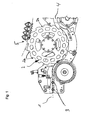
- Fig. 1 is shown in plan view of the designated 1 inlet of a bottling plant, for example, where a sawtooth star, generally designated 2, is provided, the bottles brings on division, the incoming bottles are designated 3.
- a sawtooth star generally designated 2
- the bottles brings on division, the incoming bottles are designated 3.
- the bottles brought to pitch by the sawtooth star can be supplied to a bypass 4 or directly to a rinser 5 which is reproduced only by way of an indication, whereupon it does not come closer here.
- Each sawtooth cutout designated 2a in the figures, has an approximately radially aligned abutment edge 6 and a curved opposite side 7.
- a blade member 8 is provided on the underside of the sawtooth star 2, which is acted upon by a compression spring 9, which drives the blade member to the outside.
- the blade member has a stop tab 10, while at the bottom of the sawtooth star 2, a further tab member 11 is fixed, wherein the spring 9 is clamped between the two tab members 10 and 11, as can be seen in particular Fig. 3 results.
- Fig. 2 can be seen when inserting the necks of the bottles 3 through the blade member 8, which has an inclined edge 8a in the front, pressed against the stop edge 6, so that an exact pitch due to the pitch of the sawtooth 2a is ensured.
- the bottle 3 is fixed so that it can not perform unwanted additional movements during further transport.
- the blade elements 8 are guided laterally in rails 13 in the region of the underside of the sawtooth star 2 approximately radially displaceable.
- the spring 9 can act with the aid of the inlet bevel 8a on the blade element 8 against the abutment edge 6.
- the spring 9 is clamped between a stop tab 10 on the blade element on the one hand and a stop tab 11 on the other hand fixed to the underside of the sawtooth star 2, respectively.
- Fig. 3 results, the blade elements 8 in grooves, generally designated 12, which are placed in the bottom of the sawtooth star 2, positioned.
Landscapes
- Engineering & Computer Science (AREA)
- Mechanical Engineering (AREA)
- Filling Of Jars Or Cans And Processes For Cleaning And Sealing Jars (AREA)
Description
- Die Erfindung richtet sich auf eine Vorrichtung zur Fixlerung eines Flaschenhalses In einem Sägezahnstern einer Flaschenabfüllanlage, Insbesondere von PET-Flaschen.
- Am Einlauf derartiger Abfüllanlagen wird in der Regel eln Förderelement vorgesehen, welches als sogenannter Sägezahnstern ausgestaltet Ist. Dieser Stern ist in der Regel unmittelbar hinter der Einlaufscheibe vorgesehen, wobei der Stern die von der Einlaufscheibe beschleunigten Flaschen auf Teilung bringt (
DE 697 28 396 T2 ). - Es hat sich gezeigt, dass die einlaufenden Flaschen teilweise zu tanzen beginnen und ggf. die gewünschte Teilung verlieren, so dass es zu Zerstörungen kommen kann, beispielsweise an den Greifarmen der für die Flaschen vorgesehenen Greifer.
- Aus der
EP 0 927 683 A1 ist eine gattungsgemäße Einlaufscheibe bekannt, bel der Beutelverpackungen mittels eines federbelasteten Schwenkhebels fixiert werden, wozu dieser Schwenkhebel über eine Steuerkurve vor Aufnahme der Behälter geöffnet werden muss. Eine vergleichbare Vorrichtung ist aus derFR 2 824 641 A1 - Hier setzt die Erfindung an, deren Aufgabe darin besteht, eine passive, exakte Zentrierung bzw. Fixierung der einlaufenden Flaschen in den Sägezahnstern zu erreichen bei gleichzeitiger Beruhigung der Eigenbewegung.
- Mit einer Vorrichtung der eingangs bezeichneten Art wird diese Aufgabe gemäß der Erfindung dadurch gelöst, dass jedem Sägezahnausschnitt an der der etwa radial ausgerichteten Anlagekante gegenüberliegenden Seite des Sägezahnausschnittes ein federbelastetes Klingenelement zugeordnet ist.
- Mit einem derartigen federbelasteten Klingenelement wird erreicht, dass der Flaschenhals exakt in die Anlaufkante des Sägezahnausschnittes gedrückt wird, womit sich automatisch eine exakte Einhaltung der Teilungsabstände ergibt. Gleichzeitig wird erreicht, dass eine evtl. tanzende oder vibrierende Flasche durch diese festere Fixierung in ihrer Bewegung beruhigt wird.
- Ausgestaltungen der Erfindung ergeben sich aus den Unteransprüchen. Dabei kann beispielsweise vorgesehen sein, dass das Klingenelement im stirnseitigen Bereich eine Einlaufschräge aufweist, was die Übernahme der in den Sägezahnstern einlaufenden Flaschen erleichtert.
- Erfindungsgemäß ist das Klingenelement in seitlichen Schienen am Sägezahnstern geführt, wobei diese Führungsschienen auch als integraler Bestandteil des Sägezahnsternes selbst ausgebildet sein können.
- Vorteilhaft weist das Klingenelement eine Anschlaglasche für eine Druckfeder an dem der Einlaufseite gegenüberliegenden Ende auf. Damit ist eine einfache technische Verwirklichung der Federbelastung eines entsprechenden Klingenelementes gewährleistet, wobei gleichzeitig erreicht ist, dass evtl. beschädigte Federn leicht ausgewechselt werden können.
- Grundsätzlich kann das Klingenelement mit einem Anschlag versehen sein. Es ist dabei erfindungsgemäß vorgesehen, dass die Feder ein Wegbegrenzungselement aufweist.
- Erfindungsgemäß ist das Klinkenelement derart im Sägezahnstern eingebettet, dass seine Wirkkante der Anlagekante des jeweiligen Sägezahnausschnittes gegenüberliegt.
- Weitere Merkmale, Einzelheiten und Vorteile der Erfindung ergeben sich aufgrund der nachfolgenden Beschreibung sowie anhand der Zeichnung. Diese zeigt in
-
Fig. 1 eine Aufsicht auf den Einlaufbereich einer Flaschenabfüllanlage mit einem Sägezahnstern nach dem Stand der Technik, -
Fig. 2 eine räumliche Darstellung des erfindungsgemäßen Sägezahnsternes von oben sowie in -
Fig. 3 einen Teilausriss in räumlicher Darstellung eines Bereiches des Sägezahnsternes in Unteransicht. - In
Fig. 1 ist in Aufsicht der mit 1 bezeichnete Einlauf einer beispielsweise Flaschenabfüllanlage dargestellt, wobei dort ein Sägezahnstern, allgemein mit 2 bezeichnet, vorgesehen ist, der Flaschen auf Teilung bringt, wobei die einlaufenden Flaschen mit 3 bezeichnet sind. - Die vom Sägezahnstern auf Teilung gebrachten Flaschen können, je nach Konstruktion, einem Bypass 4 zugeführt werden oder direkt einem nur andeutungsweise wiedergegebenen Rinser 5, worauf es hier nicht näher ankommt.
- Jeder Sägezahnausschnitt, in den Figuren mit 2a bezeichnet, weist eine etwa radial ausgerichtete Anlagekante 6 auf und eine geschwungene gegenüberliegende Seite 7.
- Etwa im inneren Einlaufbereich der Seite 7 des Sägezahnausschnittes 2 ist ein Klingenelement 8 auf der Unterseite des Sägezahnsternes 2 vorgesehen, der von einer Druckfeder 9 beaufschlagt ist, die das Klingenelement nach außen treibt. Zur Fixierung der Feder 9 weist das Klingenelement eine Anschlaglasche 10 auf, während an der Unterseite des Sägezahnsternes 2 ein weiteres Laschenelement 11 fixiert ist, wobei die Feder 9 zwischen den beiden Laschenelementen 10 und 11 eingespannt ist, wie sich dies insbesondere aus
Fig. 3 ergibt. - Nicht näher dargestellt ist dabei, dass entweder in der Führung der Feder 9 oder am Klingenelement 8 Wegbegrenzungsmittel vorgesehen sind, die dafür sorgen, dass das Klingenelement 8 nicht zu weit nach außen geschoben wird.
- Wie auch aus
Fig. 2 ersichtlich, werden beim Einführen der Hälse der Flaschen 3 diese durch das Klingenelement 8, das im vorderen Bereich eine schräggestellte Wirkkante 8a aufweist, gegen die Anschlagkante 6 gedrückt, so dass eine exakte Teilung aufgrund der Teilung der Sägezahnabschnitte 2a sichergestellt ist. Gleichzeitig wird die Flasche 3 so fixiert, dass sie keine ungewollten Zusatzbewegungen beim Weitertransport ausführen kann. - Die Klingenelemente 8 sind seitlich in Schienen 13 im Bereich der Unterseite des Sägezahnsternes 2 etwa radial verschiebbar geführt.
- Zur Ausübung des Anpressdruckes des Flaschenhalses kann mit Hilfe der Einlaufschräge 8a am Klingenelement 8 gegen die Anlagekante 6 die Feder 9 wirken. Die Feder 9 ist zwischen einer Anschlaglasche 10 am Klingenelement einerseits und einer Anschlaglasche 11 andererseits, die ortsfest an der Unterseite des Sägezahnsternes 2 jeweils fixiert ist, eingespannt. Hierbei können Wegbegrenzungsmittel vorgesehen sein, was in den Figuren nicht näher dargestellt ist, sei es, dass das Klingenelement 8 entsprechende Anschläge oder Wülste aufweist oder der Federweg auf andere Weise begrenzt ist.
- Wie sich aus
Fig. 3 ergibt, sind die Klingenelemente 8 in Nuten, allgemein mit 12 bezeichnet, die in der Unterseite des Sägezahnsternes 2 eingebracht sind, positioniert. - Natürlich ist das beschriebene Ausführungsbeispiel der Erfindung wie beansprucht noch in vielfacher Hinsicht abzuändern, ohne den Grundgedanken zu verlassen. So ist insbesondere die Art der Federung der Fixierung sowie der Führung der Klingenelemente 8 nicht auf die dargestellte technische Lösung beschränkt, hier können andere äquivalente Lösungen vorgesehen sein.
Claims (3)
- Sägezahnstern mit Vorrichtung zur Fixierung eines Flaschenhalses einer Flaschenabfüllanlage, insbesondere von PET-Flaschen,
wobei das Sägezahnstern Sägezahnausschnitte (2a) aufweist und jeder Sägezahnausschnitt (2a) eine etwa radial ausgerichtete Anlagekante (6) aufweist,
wobei jedem Sägezahnausschnitt (2a) an der der etwa radial ausgerichteten Anlagekante (6) gegenüberliegenden Seite (7) des Sägezahnausschnittes (2a) ein federbelastetes Klingenelement (8) zugeordnet ist,
dadurch gekennzeichnet, dass das Klingenelement (8) seitlich in Schienen (13) im Bereich der Unterseite des Sägezahnsternes (2) etwa radial verschiebbar geführt ist,
wobei das Klingenelement (8) von einer Druckfeder (9) beaufschlagt ist, die das Klingenelement (8) nach außen treibt,
und wobei das Klingenelement (8) im stirnseitigen Bereich eine Einlaufschräge (8a) aufweist, und derart im Sägezahnstern (2) eingebettet ist, dass die Einlaufschräge (8a) der Anlagekante (6) des jeweiligen Sägezahnausschnittes (2a) gegenüberliegt,
so dass mittels der Einlaufschräge (8a) der Flaschenhals gegen die Anlagekante (6) des Sägezahns gedrückt wird. - Vorrichtung nach einem der vorangehenden Ansprüche, dadurch gekennzeichnet, dass das Klingenelement (8) eine Anschlaglasche (10) für die Druckfeder (9) an dem der Einlaufseite gegenüberliegenden Ende aufweist.
- Vorrichtung nach einem der vorangehenden Ansprüche, dadurch gekennzeichnet, dass die Feder (9) ein Wegbegrenzungselement aufweist.
Applications Claiming Priority (2)
| Application Number | Priority Date | Filing Date | Title |
|---|---|---|---|
| DE102008022705A DE102008022705A1 (de) | 2008-05-07 | 2008-05-07 | Vorrichtung zur Fixierung eines Flaschenhalses in einem Sägezahnstern einer Flachenabfüllanlage |
| PCT/EP2009/003002 WO2009135596A1 (de) | 2008-05-07 | 2009-04-24 | Vorrichtung zur fixierung eines flaschenhalses in einem sägezahnstern einer flaschenabfüllanlage |
Publications (2)
| Publication Number | Publication Date |
|---|---|
| EP2285716A1 EP2285716A1 (de) | 2011-02-23 |
| EP2285716B1 true EP2285716B1 (de) | 2013-11-20 |
Family
ID=40834433
Family Applications (1)
| Application Number | Title | Priority Date | Filing Date |
|---|---|---|---|
| EP09741815.6A Not-in-force EP2285716B1 (de) | 2008-05-07 | 2009-04-24 | Sägezahnstern mit vorrichtung zur fixierung eines flaschenhalses |
Country Status (3)
| Country | Link |
|---|---|
| EP (1) | EP2285716B1 (de) |
| DE (1) | DE102008022705A1 (de) |
| WO (1) | WO2009135596A1 (de) |
Families Citing this family (10)
| Publication number | Priority date | Publication date | Assignee | Title |
|---|---|---|---|---|
| US9061874B2 (en) | 2011-02-10 | 2015-06-23 | Khs Gmbh | Container transport device having pliable bottle supports |
| DE102011010954A1 (de) | 2011-02-10 | 2012-08-16 | Khs Gmbh | Nachgiebige Flaschenauflage |
| DE102012103525A1 (de) * | 2012-04-20 | 2013-10-24 | Krones Ag | Vorrichtung zum Aufnehmen von mit einem Halsring versehenen Flaschen in einem Verschließer |
| DE102012104956A1 (de) * | 2012-06-08 | 2013-12-12 | Krones Ag | Vorrichtung zum Transportieren von Behältnissen mit Teilungsverzug |
| DE102012011367A1 (de) | 2012-06-11 | 2013-12-12 | Khs Gmbh | Greiferanordnung |
| DE102012217457A1 (de) | 2012-09-26 | 2014-05-15 | Krones Aktiengesellschaft | Förderabschnitt mit rotierendem einteil- und/oder förderstern zur herstellung eines teilungsverzugs zwischen aufeinander folgenden behältern |
| DE102013214185A1 (de) * | 2013-07-19 | 2015-01-22 | Krones Ag | Transportvorrichtung für eine Behälterbehandlungsmaschine |
| DE102014103394B4 (de) * | 2014-03-13 | 2025-12-18 | Krones Ag | Vorrichtung und Verfahren zum Transportieren von Kunststoffvorformlingen |
| DE102015224731A1 (de) * | 2015-12-09 | 2017-06-14 | Krones Ag | Behandlungsmaschine für Behälter |
| CN114590764B (zh) * | 2022-03-11 | 2023-05-05 | 山东鲁润阿胶健康产业有限公司 | 一种阿胶浆加工用智能灌封机 |
Citations (3)
| Publication number | Priority date | Publication date | Assignee | Title |
|---|---|---|---|---|
| US4388989A (en) * | 1981-07-23 | 1983-06-21 | Hoppmann Corporation | Continuous rotary method of transporting articles |
| FR2736299A1 (fr) * | 1995-07-05 | 1997-01-10 | Sidel Sa | Procede et dispositif d'indexation angulaire pour disposer une preforme, une ebauche ou un recipient dans une position angulaire predeterminee, et preforme ou ebauche agencee pour leur mise en oeuvre |
| US20030106778A1 (en) * | 2001-12-11 | 2003-06-12 | Hurst Richard Francis | Bottle indexing wheel with radially resilient teeth |
Family Cites Families (7)
| Publication number | Priority date | Publication date | Assignee | Title |
|---|---|---|---|---|
| FR1196430A (fr) * | 1958-05-28 | 1959-11-24 | Brondel | Perfectionnement aux machines à étiqueter |
| GB2187720A (en) * | 1986-03-11 | 1987-09-16 | Metal Box Plc | Capping or uncapping containers |
| US5772001A (en) | 1996-04-18 | 1998-06-30 | B & H Manufacturing Company, Inc. | Star wheel system |
| EP0927683A4 (de) * | 1997-04-30 | 2001-04-25 | Mitsubishi Heavy Ind Ltd | Vorrichtung zum fördern, zuführen und füllen von ungeformten behältern und verfahren zum fördern und zuführen derselben |
| DE10040374B4 (de) * | 2000-08-18 | 2004-08-05 | Tetra Laval Holdings & Finance S.A. | Vorrichtung zum Haltern und Arretieren eines runden Körpers |
| FR2824541A1 (fr) * | 2001-05-09 | 2002-11-15 | Rosebud Consulting Ltd | Dispositif de prehension de recipients et procede de transport correspondant |
| DE10140315A1 (de) * | 2001-08-16 | 2003-03-06 | Tetra Laval Holdings & Finance | Greifer zum Haltern und Bewegen von Hohlkörpern |
-
2008
- 2008-05-07 DE DE102008022705A patent/DE102008022705A1/de not_active Withdrawn
-
2009
- 2009-04-24 EP EP09741815.6A patent/EP2285716B1/de not_active Not-in-force
- 2009-04-24 WO PCT/EP2009/003002 patent/WO2009135596A1/de not_active Ceased
Patent Citations (3)
| Publication number | Priority date | Publication date | Assignee | Title |
|---|---|---|---|---|
| US4388989A (en) * | 1981-07-23 | 1983-06-21 | Hoppmann Corporation | Continuous rotary method of transporting articles |
| FR2736299A1 (fr) * | 1995-07-05 | 1997-01-10 | Sidel Sa | Procede et dispositif d'indexation angulaire pour disposer une preforme, une ebauche ou un recipient dans une position angulaire predeterminee, et preforme ou ebauche agencee pour leur mise en oeuvre |
| US20030106778A1 (en) * | 2001-12-11 | 2003-06-12 | Hurst Richard Francis | Bottle indexing wheel with radially resilient teeth |
Also Published As
| Publication number | Publication date |
|---|---|
| EP2285716A1 (de) | 2011-02-23 |
| DE102008022705A1 (de) | 2009-11-19 |
| WO2009135596A1 (de) | 2009-11-12 |
Similar Documents
| Publication | Publication Date | Title |
|---|---|---|
| EP2285716B1 (de) | Sägezahnstern mit vorrichtung zur fixierung eines flaschenhalses | |
| EP2424799B1 (de) | Vorrichtung zur übergabe von im neckbereich mittels greifern od. dgl. gehaltenen flaschen | |
| EP3286118B1 (de) | Behältergreifer sowie transportvorrichtung zum transportieren von behältern | |
| EP2858793B1 (de) | Greiferanordnung | |
| EP2673222B1 (de) | Behältertransportvorrichtung mit nachgiebigen flaschenauflagen | |
| EP2882673B1 (de) | Behältergreifer sowie transportelement mit derartigen behältergreifern | |
| WO2008009410A1 (de) | Behandlungsmaschine für flaschen oder dergleichen behälter | |
| DE102014117358A1 (de) | Flaschenklammer mit Kraftverstärkung | |
| DE102009028404A1 (de) | Werkzeugmaschine mit einer Schutzhaube | |
| EP3090969A1 (de) | Vorrichtung zum puffern von behälterverschlüssen | |
| DE2029292A1 (de) | Vorrichtung zur Abgabe von Ventilen aus einem Vorratsbehälter | |
| EP3044100B1 (de) | Formatteil sowie formatteilbefestigung | |
| EP1669321B1 (de) | Verschliessmaschine für Flaschen oder dergleichen Behälter | |
| EP2730534B1 (de) | Vorrichtung zum Aufbringen eines Verschlusses auf einen Behälter | |
| DE102011010954A1 (de) | Nachgiebige Flaschenauflage | |
| EP3645431B1 (de) | Klammervorrichtung zum halten eines behälters in einer behälterbehandlungsanlage | |
| DE2045950A1 (de) | Vibrationsförderer | |
| DE102015004591A1 (de) | Vorrichtung zum Schneiden eines Fadens | |
| DE102012005300A1 (de) | Vorrichtung zum zumindest teilweisen Aufschrauben eines Drehverschlusses auf eine Flasche | |
| DE4129452A1 (de) | Verschliessmaschine | |
| DE102020108181A1 (de) | Vorrichtung zur austauschbaren Befestigung von Formatteilen | |
| DE202017105954U1 (de) | Clipmaschine, Vorschubmechanismus des Clips und Regler der Lange des Hubs des Oberverschließwerkzeugs für ihn | |
| DE102020126410A1 (de) | Hilfsvorrichtung zur Montage von Lagerschalen an Pleueldeckeln sowie Verfahren zur Herstellung eines Pleuels | |
| DE102004010124A1 (de) | Schraubkopf | |
| DE496319C (de) | Sicherheitsvorrichtung an umlaufenden Flaschenbehandlungsmaschinen |
Legal Events
| Date | Code | Title | Description |
|---|---|---|---|
| PUAI | Public reference made under article 153(3) epc to a published international application that has entered the european phase |
Free format text: ORIGINAL CODE: 0009012 |
|
| 17P | Request for examination filed |
Effective date: 20101207 |
|
| AK | Designated contracting states |
Kind code of ref document: A1 Designated state(s): AT BE BG CH CY CZ DE DK EE ES FI FR GB GR HR HU IE IS IT LI LT LU LV MC MK MT NL NO PL PT RO SE SI SK TR |
|
| AX | Request for extension of the european patent |
Extension state: AL BA RS |
|
| DAX | Request for extension of the european patent (deleted) | ||
| 17Q | First examination report despatched |
Effective date: 20120524 |
|
| GRAP | Despatch of communication of intention to grant a patent |
Free format text: ORIGINAL CODE: EPIDOSNIGR1 |
|
| INTG | Intention to grant announced |
Effective date: 20130702 |
|
| GRAS | Grant fee paid |
Free format text: ORIGINAL CODE: EPIDOSNIGR3 |
|
| GRAA | (expected) grant |
Free format text: ORIGINAL CODE: 0009210 |
|
| AK | Designated contracting states |
Kind code of ref document: B1 Designated state(s): AT BE BG CH CY CZ DE DK EE ES FI FR GB GR HR HU IE IS IT LI LT LU LV MC MK MT NL NO PL PT RO SE SI SK TR |
|
| REG | Reference to a national code |
Ref country code: GB Ref legal event code: FG4D Free format text: NOT ENGLISH |
|
| REG | Reference to a national code |
Ref country code: CH Ref legal event code: EP |
|
| REG | Reference to a national code |
Ref country code: AT Ref legal event code: REF Ref document number: 641461 Country of ref document: AT Kind code of ref document: T Effective date: 20131215 |
|
| REG | Reference to a national code |
Ref country code: IE Ref legal event code: FG4D Free format text: LANGUAGE OF EP DOCUMENT: GERMAN |
|
| REG | Reference to a national code |
Ref country code: DE Ref legal event code: R096 Ref document number: 502009008381 Country of ref document: DE Effective date: 20140116 |
|
| REG | Reference to a national code |
Ref country code: NL Ref legal event code: VDEP Effective date: 20131120 |
|
| REG | Reference to a national code |
Ref country code: LT Ref legal event code: MG4D |
|
| PG25 | Lapsed in a contracting state [announced via postgrant information from national office to epo] |
Ref country code: NO Free format text: LAPSE BECAUSE OF FAILURE TO SUBMIT A TRANSLATION OF THE DESCRIPTION OR TO PAY THE FEE WITHIN THE PRESCRIBED TIME-LIMIT Effective date: 20140220 Ref country code: HR Free format text: LAPSE BECAUSE OF FAILURE TO SUBMIT A TRANSLATION OF THE DESCRIPTION OR TO PAY THE FEE WITHIN THE PRESCRIBED TIME-LIMIT Effective date: 20131120 Ref country code: LT Free format text: LAPSE BECAUSE OF FAILURE TO SUBMIT A TRANSLATION OF THE DESCRIPTION OR TO PAY THE FEE WITHIN THE PRESCRIBED TIME-LIMIT Effective date: 20131120 Ref country code: FI Free format text: LAPSE BECAUSE OF FAILURE TO SUBMIT A TRANSLATION OF THE DESCRIPTION OR TO PAY THE FEE WITHIN THE PRESCRIBED TIME-LIMIT Effective date: 20131120 Ref country code: SE Free format text: LAPSE BECAUSE OF FAILURE TO SUBMIT A TRANSLATION OF THE DESCRIPTION OR TO PAY THE FEE WITHIN THE PRESCRIBED TIME-LIMIT Effective date: 20131120 Ref country code: IS Free format text: LAPSE BECAUSE OF FAILURE TO SUBMIT A TRANSLATION OF THE DESCRIPTION OR TO PAY THE FEE WITHIN THE PRESCRIBED TIME-LIMIT Effective date: 20140320 Ref country code: NL Free format text: LAPSE BECAUSE OF FAILURE TO SUBMIT A TRANSLATION OF THE DESCRIPTION OR TO PAY THE FEE WITHIN THE PRESCRIBED TIME-LIMIT Effective date: 20131120 |
|
| PG25 | Lapsed in a contracting state [announced via postgrant information from national office to epo] |
Ref country code: LV Free format text: LAPSE BECAUSE OF FAILURE TO SUBMIT A TRANSLATION OF THE DESCRIPTION OR TO PAY THE FEE WITHIN THE PRESCRIBED TIME-LIMIT Effective date: 20131120 Ref country code: ES Free format text: LAPSE BECAUSE OF FAILURE TO SUBMIT A TRANSLATION OF THE DESCRIPTION OR TO PAY THE FEE WITHIN THE PRESCRIBED TIME-LIMIT Effective date: 20131120 |
|
| PG25 | Lapsed in a contracting state [announced via postgrant information from national office to epo] |
Ref country code: PT Free format text: LAPSE BECAUSE OF FAILURE TO SUBMIT A TRANSLATION OF THE DESCRIPTION OR TO PAY THE FEE WITHIN THE PRESCRIBED TIME-LIMIT Effective date: 20140320 |
|
| PG25 | Lapsed in a contracting state [announced via postgrant information from national office to epo] |
Ref country code: EE Free format text: LAPSE BECAUSE OF FAILURE TO SUBMIT A TRANSLATION OF THE DESCRIPTION OR TO PAY THE FEE WITHIN THE PRESCRIBED TIME-LIMIT Effective date: 20131120 |
|
| REG | Reference to a national code |
Ref country code: DE Ref legal event code: R097 Ref document number: 502009008381 Country of ref document: DE |
|
| PG25 | Lapsed in a contracting state [announced via postgrant information from national office to epo] |
Ref country code: PL Free format text: LAPSE BECAUSE OF FAILURE TO SUBMIT A TRANSLATION OF THE DESCRIPTION OR TO PAY THE FEE WITHIN THE PRESCRIBED TIME-LIMIT Effective date: 20131120 Ref country code: RO Free format text: LAPSE BECAUSE OF FAILURE TO SUBMIT A TRANSLATION OF THE DESCRIPTION OR TO PAY THE FEE WITHIN THE PRESCRIBED TIME-LIMIT Effective date: 20131120 Ref country code: SK Free format text: LAPSE BECAUSE OF FAILURE TO SUBMIT A TRANSLATION OF THE DESCRIPTION OR TO PAY THE FEE WITHIN THE PRESCRIBED TIME-LIMIT Effective date: 20131120 Ref country code: CZ Free format text: LAPSE BECAUSE OF FAILURE TO SUBMIT A TRANSLATION OF THE DESCRIPTION OR TO PAY THE FEE WITHIN THE PRESCRIBED TIME-LIMIT Effective date: 20131120 |
|
| PLBE | No opposition filed within time limit |
Free format text: ORIGINAL CODE: 0009261 |
|
| STAA | Information on the status of an ep patent application or granted ep patent |
Free format text: STATUS: NO OPPOSITION FILED WITHIN TIME LIMIT |
|
| PG25 | Lapsed in a contracting state [announced via postgrant information from national office to epo] |
Ref country code: DK Free format text: LAPSE BECAUSE OF FAILURE TO SUBMIT A TRANSLATION OF THE DESCRIPTION OR TO PAY THE FEE WITHIN THE PRESCRIBED TIME-LIMIT Effective date: 20131120 |
|
| 26N | No opposition filed |
Effective date: 20140821 |
|
| PG25 | Lapsed in a contracting state [announced via postgrant information from national office to epo] |
Ref country code: MC Free format text: LAPSE BECAUSE OF FAILURE TO SUBMIT A TRANSLATION OF THE DESCRIPTION OR TO PAY THE FEE WITHIN THE PRESCRIBED TIME-LIMIT Effective date: 20131120 Ref country code: LU Free format text: LAPSE BECAUSE OF FAILURE TO SUBMIT A TRANSLATION OF THE DESCRIPTION OR TO PAY THE FEE WITHIN THE PRESCRIBED TIME-LIMIT Effective date: 20140424 |
|
| REG | Reference to a national code |
Ref country code: CH Ref legal event code: PL |
|
| REG | Reference to a national code |
Ref country code: DE Ref legal event code: R097 Ref document number: 502009008381 Country of ref document: DE Effective date: 20140821 |
|
| GBPC | Gb: european patent ceased through non-payment of renewal fee |
Effective date: 20140424 |
|
| REG | Reference to a national code |
Ref country code: IE Ref legal event code: MM4A |
|
| PG25 | Lapsed in a contracting state [announced via postgrant information from national office to epo] |
Ref country code: CH Free format text: LAPSE BECAUSE OF NON-PAYMENT OF DUE FEES Effective date: 20140430 Ref country code: LI Free format text: LAPSE BECAUSE OF NON-PAYMENT OF DUE FEES Effective date: 20140430 Ref country code: GB Free format text: LAPSE BECAUSE OF NON-PAYMENT OF DUE FEES Effective date: 20140424 |
|
| PG25 | Lapsed in a contracting state [announced via postgrant information from national office to epo] |
Ref country code: SI Free format text: LAPSE BECAUSE OF FAILURE TO SUBMIT A TRANSLATION OF THE DESCRIPTION OR TO PAY THE FEE WITHIN THE PRESCRIBED TIME-LIMIT Effective date: 20131120 |
|
| PG25 | Lapsed in a contracting state [announced via postgrant information from national office to epo] |
Ref country code: IE Free format text: LAPSE BECAUSE OF NON-PAYMENT OF DUE FEES Effective date: 20140424 |
|
| REG | Reference to a national code |
Ref country code: AT Ref legal event code: MM01 Ref document number: 641461 Country of ref document: AT Kind code of ref document: T Effective date: 20140424 |
|
| PG25 | Lapsed in a contracting state [announced via postgrant information from national office to epo] |
Ref country code: AT Free format text: LAPSE BECAUSE OF NON-PAYMENT OF DUE FEES Effective date: 20140424 |
|
| PG25 | Lapsed in a contracting state [announced via postgrant information from national office to epo] |
Ref country code: MT Free format text: LAPSE BECAUSE OF FAILURE TO SUBMIT A TRANSLATION OF THE DESCRIPTION OR TO PAY THE FEE WITHIN THE PRESCRIBED TIME-LIMIT Effective date: 20131120 |
|
| REG | Reference to a national code |
Ref country code: FR Ref legal event code: PLFP Year of fee payment: 8 |
|
| PG25 | Lapsed in a contracting state [announced via postgrant information from national office to epo] |
Ref country code: CY Free format text: LAPSE BECAUSE OF FAILURE TO SUBMIT A TRANSLATION OF THE DESCRIPTION OR TO PAY THE FEE WITHIN THE PRESCRIBED TIME-LIMIT Effective date: 20131120 Ref country code: BG Free format text: LAPSE BECAUSE OF FAILURE TO SUBMIT A TRANSLATION OF THE DESCRIPTION OR TO PAY THE FEE WITHIN THE PRESCRIBED TIME-LIMIT Effective date: 20131120 Ref country code: GR Free format text: LAPSE BECAUSE OF FAILURE TO SUBMIT A TRANSLATION OF THE DESCRIPTION OR TO PAY THE FEE WITHIN THE PRESCRIBED TIME-LIMIT Effective date: 20140221 |
|
| PG25 | Lapsed in a contracting state [announced via postgrant information from national office to epo] |
Ref country code: BE Free format text: LAPSE BECAUSE OF FAILURE TO SUBMIT A TRANSLATION OF THE DESCRIPTION OR TO PAY THE FEE WITHIN THE PRESCRIBED TIME-LIMIT Effective date: 20140430 Ref country code: TR Free format text: LAPSE BECAUSE OF FAILURE TO SUBMIT A TRANSLATION OF THE DESCRIPTION OR TO PAY THE FEE WITHIN THE PRESCRIBED TIME-LIMIT Effective date: 20131120 Ref country code: HU Free format text: LAPSE BECAUSE OF FAILURE TO SUBMIT A TRANSLATION OF THE DESCRIPTION OR TO PAY THE FEE WITHIN THE PRESCRIBED TIME-LIMIT; INVALID AB INITIO Effective date: 20090424 |
|
| REG | Reference to a national code |
Ref country code: FR Ref legal event code: PLFP Year of fee payment: 9 |
|
| REG | Reference to a national code |
Ref country code: FR Ref legal event code: PLFP Year of fee payment: 10 |
|
| PG25 | Lapsed in a contracting state [announced via postgrant information from national office to epo] |
Ref country code: MK Free format text: LAPSE BECAUSE OF FAILURE TO SUBMIT A TRANSLATION OF THE DESCRIPTION OR TO PAY THE FEE WITHIN THE PRESCRIBED TIME-LIMIT Effective date: 20131120 |
|
| PGFP | Annual fee paid to national office [announced via postgrant information from national office to epo] |
Ref country code: DE Payment date: 20180420 Year of fee payment: 10 |
|
| PGFP | Annual fee paid to national office [announced via postgrant information from national office to epo] |
Ref country code: FR Payment date: 20180420 Year of fee payment: 10 Ref country code: IT Payment date: 20180423 Year of fee payment: 10 |
|
| REG | Reference to a national code |
Ref country code: DE Ref legal event code: R119 Ref document number: 502009008381 Country of ref document: DE |
|
| PG25 | Lapsed in a contracting state [announced via postgrant information from national office to epo] |
Ref country code: DE Free format text: LAPSE BECAUSE OF NON-PAYMENT OF DUE FEES Effective date: 20191101 |
|
| PG25 | Lapsed in a contracting state [announced via postgrant information from national office to epo] |
Ref country code: FR Free format text: LAPSE BECAUSE OF NON-PAYMENT OF DUE FEES Effective date: 20190430 |
|
| PG25 | Lapsed in a contracting state [announced via postgrant information from national office to epo] |
Ref country code: IT Free format text: LAPSE BECAUSE OF NON-PAYMENT OF DUE FEES Effective date: 20190424 |