EP2286032B1 - Device for halting vehicle traffic - Google Patents
Device for halting vehicle traffic Download PDFInfo
- Publication number
- EP2286032B1 EP2286032B1 EP09728888.0A EP09728888A EP2286032B1 EP 2286032 B1 EP2286032 B1 EP 2286032B1 EP 09728888 A EP09728888 A EP 09728888A EP 2286032 B1 EP2286032 B1 EP 2286032B1
- Authority
- EP
- European Patent Office
- Prior art keywords
- mechanisms
- mobile
- shaft
- stop
- roller
- Prior art date
- Legal status (The legal status is an assumption and is not a legal conclusion. Google has not performed a legal analysis and makes no representation as to the accuracy of the status listed.)
- Not-in-force
Links
- 230000007246 mechanism Effects 0.000 claims description 145
- 230000009471 action Effects 0.000 claims description 22
- 238000013016 damping Methods 0.000 claims description 14
- 238000006073 displacement reaction Methods 0.000 claims description 14
- 230000009467 reduction Effects 0.000 claims description 14
- 238000007373 indentation Methods 0.000 claims description 7
- 230000005484 gravity Effects 0.000 claims description 6
- 230000002441 reversible effect Effects 0.000 claims description 4
- 230000000694 effects Effects 0.000 claims description 2
- 230000004888 barrier function Effects 0.000 description 14
- 238000001514 detection method Methods 0.000 description 2
- 238000004088 simulation Methods 0.000 description 2
- 230000004913 activation Effects 0.000 description 1
- 230000001154 acute effect Effects 0.000 description 1
- 230000000052 comparative effect Effects 0.000 description 1
- 230000002498 deadly effect Effects 0.000 description 1
- 239000000446 fuel Substances 0.000 description 1
- 230000002779 inactivation Effects 0.000 description 1
- 239000007937 lozenge Substances 0.000 description 1
- 230000000149 penetrating effect Effects 0.000 description 1
- 230000002093 peripheral effect Effects 0.000 description 1
- 230000000452 restraining effect Effects 0.000 description 1
- 230000011664 signaling Effects 0.000 description 1
Images


Classifications
-
- E—FIXED CONSTRUCTIONS
- E01—CONSTRUCTION OF ROADS, RAILWAYS, OR BRIDGES
- E01F—ADDITIONAL WORK, SUCH AS EQUIPPING ROADS OR THE CONSTRUCTION OF PLATFORMS, HELICOPTER LANDING STAGES, SIGNS, SNOW FENCES, OR THE LIKE
- E01F13/00—Arrangements for obstructing or restricting traffic, e.g. gates, barricades ; Preventing passage of vehicles of selected category or dimensions
- E01F13/12—Arrangements for obstructing or restricting traffic, e.g. gates, barricades ; Preventing passage of vehicles of selected category or dimensions for forcibly arresting or disabling vehicles, e.g. spiked mats
- E01F13/123—Arrangements for obstructing or restricting traffic, e.g. gates, barricades ; Preventing passage of vehicles of selected category or dimensions for forcibly arresting or disabling vehicles, e.g. spiked mats depressible or retractable below the traffic surface, e.g. one-way spike barriers, power-controlled prong barriers
-
- E—FIXED CONSTRUCTIONS
- E01—CONSTRUCTION OF ROADS, RAILWAYS, OR BRIDGES
- E01F—ADDITIONAL WORK, SUCH AS EQUIPPING ROADS OR THE CONSTRUCTION OF PLATFORMS, HELICOPTER LANDING STAGES, SIGNS, SNOW FENCES, OR THE LIKE
- E01F13/00—Arrangements for obstructing or restricting traffic, e.g. gates, barricades ; Preventing passage of vehicles of selected category or dimensions
- E01F13/10—Vehicle barriers specially adapted for allowing passage in one direction only
- E01F13/105—Vehicle barriers specially adapted for allowing passage in one direction only depressible by right-way traffic, e.g. pivotally; actuated by wrong-way traffic
Definitions
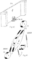
- the present invention relates to a device for halting the motor vehicles traffic in one direction, for example, in the opposite to the allowed direction by the traffic signalling, especially, in one-way roads accessing highways.
- the present invention also can be applied elsewhere, in which halting of motor vehicles movement is desired.
- the invention device acts instantaneously with or without external intervention.
- the device according to the invention can allow vehicles travelling in the appropriated traffic direction and reacts automatically, causing the motor vehicles immobilization which attempt to oppose a forbidden or non authorized direction, unless being disabled by mechanical command or similar.
- the present invention provides, through its different embodiments, very advantageous solutions in order to mitigate situations such as described in the previous paragraph.
- Patent FR2723239 describes a detection system of vehicles travelling on wrong direction, associated with traffic lights and one barrier, having as main drawback the high degree of sophistication and, therefore, the high cost and also the fact of being able to cause important damages not only in the vehicle travelling on wrong direction but also in a vehicle travelling on the right direction but finding the barrier closed.
- the concept behind this invention is to provide a device that does not allow a driver even to start a displacement in the opposite direction to the stipulated, for example, in a highway, a highway accessing road or an urban road.
- a first object of the invention is to provide a simple and selective device that is imperceptible to a vehicle travelling in the right direction, and automatically without any external intervention, human or electronic, preventing the vehicle movement in the opposite direction.
- the present invention provides puncturing means, causing the tyre to rupture and thus the vehicle immobilization.
- a second object of the invention is to provide a simple and selective device, which becomes imperceptible to a vehicle travelling in the right direction, and it automatically without any external intervention, human or electronic, preventing and attempting to prevent the displacement of a vehicle in the opposite direction.
- the present invention provides means, which can immobilize the motor vehicle by puncturing the wheel of the vehicle and simultaneously causing its elevation, causing the driving wheels to work against rollers or bumps, causing them to lose adherence on the pavement while they are torn. Since the tyre puncturing and tearing piece is removable, if removed, this object of the invention meets only the function of preventing the displacement of the driving wheels by the simulation of the rollers which originate its loss of adherence or ramps simulating bumps.
- a third object of the invention is to provide a control device, either manual or motorized, for activation or inactivation of the devices object of the present invention, the action on the vehicles being the same as described in the second object of the invention, but with a less degree of vehicle elevation on the roller.
- the device may only perform in the pavement the bump simulation function, depending on the achieved scale.
- This object of the invention is always imperceptible for vehicles travelling in a given allowed direction and it acts in vehicles attempting to travel in the opposite direction, unless it is disabled by an optional external command, which can make it imperceptible in both directions.
- a fourth object of the invention is to provide a manually or motorized operated device which prevents the displacement of vehicles in one of the directions, the option being able to be reversed in an easy way.
- This object of the invention has a similar actuation to the foregoing disclosed, but with the possibility of selection of the direction in which is desired it becomes imperceptible.
- This device will always have an external command for selecting the traffic direction, which can be manual and/or motorized.
- a fifth object of the invention is to provide a manually and/or motorized operated device allowing the selection of the movement interdiction direction or even the blockage in either direction or the free displacement in either direction as if there is no device. This device will always have an external command for selecting the traffic direction, which can be manually and/or motorized operated.
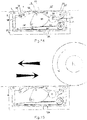
- the device consists of a box A adequately drained to embed in a road pavement, and a bank of mechanisms B1, B2, B3, B4, B5, B6 and B7 mounted within said box A.
- a bank of mechanisms B1, B2, B3, B4, B5, B6 and B7 mounted within said box A.
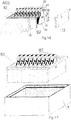
- Within the bank of mechanisms B1 to B7 there are cells defined by several vertical walls P1, P2, P3, P4, P5, P6, P7, and end walls R1, R2, R3, R4, R5, and T1, T2, T3, T4, T5, T6, T7, which are arranged parallel to each other and joined together by threaded rods 1 extending between the end walls R and T. Said walls extend in the same direction as the road axis.
- the vertical walls P and the end walls R and T serving as support to several common horizontal shafts 2, 3, 4, 5, etc., their tops serving as support pavement for vehicle tyres R.
- a driving mechanism M1, M2, M3, M4, M5, M6, M7 In each of said cells, defined by the vertical walls and by the vertical and end walls, is housed a driving mechanism M1, M2, M3, M4, M5, M6, M7.
- the device AB1 to AB7 in its several embodiments, is driven by at least a vehicle tyre R attempting to transpose or transposing it, in order to form an active barrier to the displacement of said vehicle, its repositioning being done by gravity action, assisted or not by an elastic reposition arrangement, consisting for example of springs in order to reduce the reposition time, or just by action of elastic means, for example, by springs.
- a vehicle tyre R attempting to transpose or transposing it, in order to form an active barrier to the displacement of said vehicle, its repositioning being done by gravity action, assisted or not by an elastic reposition arrangement, consisting for example of springs in order to reduce the reposition time, or just by action of elastic means, for example, by springs.
- the invention also provides a manually controlled and/or motorized operated device for driving said mechanisms M1 to M5.
- the mechanisms may be reversible, i.e. the movement of vehicles is allowed in an optional direction.
- the spikes 19 in the various embodiments of the bank of mechanisms B1 to B6 are removable and can be removed from said mechanisms M1 to M6, in which case said mechanisms only offer resistance to the displacement of vehicles, acting as rollers, which restrain the passage by loss of adherence to the driving wheel, or ramps simulating the effect of a bump, depending on the scale, without damaging the vehicle tyres R.
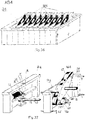
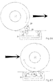
- Each mechanism M1 of the bank of mechanisms B1 according to the invention consists of a mobile piece and lever set 20,22, pivoted together on a shaft 22', the lever 22 having at its distal end from the mobile piece 20 a mobile roller 23 mounted on a shaft 23'; a jaw 18, 19, consisting of a body 18 and a removable spike 19; a mobile roller 21 mounted on a shaft 21', arranged on the mobile piece 20; a roller 24; shafts 2, 3 and 4 common to the other mechanisms M1, mounted on through holes of the intermediate vertical walls P1 and end walls R1 and T1, in which are respectively mounted the jaw 18, 19, the mobile piece 20 and the roller 24; a stop 15, arranged on inner side of the intermediate vertical wall P1 near said roller 23, and which surface provided with a damping and noise reduction element, and serving as a stop for said roller 23; a stop 16, arranged on the inner side of the intermediate vertical wall P
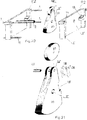
- the bank of mechanisms B1 have associated with the end wall R1, a control device (see Figs. 3, 4, 5 ) consisting of a bush 8 having a central and peripheral cogged recess; a manual driver 7, consisting of a screw, which acts on said bush 8 cogged recess and a motorized actuator 11, consisting of an engine that acts through a gear wheel 10 in a screw head 9, which in turn acts on said bush 8 cogged recess; common shafts 5 and 6, crossing said vertical walls R1, P1 and T1 through respective holes, on said common shaft 5 and joined to it by a indentation being mounted respectively the bushes 8, 13 and 25 and being mounted on said common shaft 6 of the resending pulleys 28; an elastic connecting rod 26, 26', 26" associated with each bush 25 of each mechanism M1, the elastic connecting rod 26, 26', 26" consisting of a helical spring (elastic portion) 26, a first rod portion (inelastic portion) 26' and a second rod portion (inelastic portion) 26" and being fixed by
- the bank of mechanisms B1 operates as follows:
- the control device operates as follows:
- Each mechanism M2 of the bank of mechanisms B2 according to the invention is depicted in more detail in Figs. 18 to 21 , consists of a mobile piece 20 having a removable spike 19; a mobile roller 23 mounted on a shaft 23' in said mobile piece 20; a shaft 3, common to the other mechanisms M2 housed in the other cells of the bank of mechanisms B2, which supports said mobile piece 20; a stop 15, arranged on the intermediate vertical wall P2 inner side near said removable spike 19, and which surface, provided with a damping and noise reduction element, serves as the stop to said roller 23; and a stop 16, arranged on inner side of the intermediate vertical wall P1 away from said removable spike 19, and which surface acts as a stop to said roller 23.
- the bank of mechanisms B2 operates as follows:
- Each mechanism M3 of the bank of mechanisms B3 consists of a mobile piece 20 having a removable spike 19; a mobile roller 23 mounted on a shaft 23' in said mobile piece 20; a shaft 3 common to the other mechanisms M3 housed in the other cells of the bank of mechanisms B3, which supports said mobile piece 20; a stop 15 arranged on the inner side of the intermediate vertical wall P2 near said removable spike 19, and which surface provided with a damping and noise reduction element, acts as a stop to said roller 23; a stop 30, arranged bellow the intermediate vertical wall P3, away from said mobile spike 19, and which surface, provided with a damping and noise reduction element, acts as a stop to said mobile piece 20.
- the bank of mechanisms B3 presents, associated with the end wall R3 a control device consisting of a bush 8, having peripherally and centrally a cogged recess; a manual driver 7, consisting of a screw acting on said bush 8 cogged recess and a motorized actuator 11, consisting of one engine that operates a head 9 of a screw through a gear wheel 10, the screw in turn acting on said bush 8 cogged recess; common shafts 5 and 6, crossing said vertical walls R3, P3 and T3 through respective holes, on said common shaft 5 and joined to it by a indentation being mounted respectively the bushes 8, 13 and 25 and the resending pulleys 28 being mounted on said common shaft 6; an elastic connecting rod 26, 26', 26" associated with each bush 25 of each mechanism M3, the elastic connecting rod 26, 26', 26” consisting of a helical spring (elastic part) 26, a first rod portion (inelastic part) 26' and a second road portion (inelastic part) 26" and being fixed by means of a end of the rod
- the bank of mechanisms B3 operates as follows:
- the control device operates as described in relation to the bank of mechanisms B1.
- Each mechanism M4 of the bank of mechanisms B4 according to the invention is a reversible mechanism, i.e. it allows the selection of the travelling direction.
- Each mechanism M4 depicted in more detail in Figs.
- 37 to 41 consists of a mobile piece 20 in lozenge shape, having two acute ends, each having a removable spike 19; two mobile rollers 23, mounted on shafts 23', in said mobile piece 20; a shaft 3 common to the other mechanisms M4, housed in the other cells of the bank of mechanisms B4, supporting said mobile piece 20; a eccentric drive bush 25, having a resending roller 28 mounted on a central slot of its eccentric portion; a triangular stop piece 26, arranged central and bellow the intermediate vertical wall P4, serving as a stop to a eccentric bush 25 and to a control drive, consisting of a bush 8, having peripherally and centrally a cogged recess; a manual driver 7, consisting of a screw, acting in said bush 8 cogged recess and a motorized actuator 11, consisting of one engine that operates a head 9 of a screw through a gear wheel 10, the screw in turn acting on said bush 8 cogged recess; the common shaft 5 crossing said vertical walls R4, P4 and T4 through respective holes, on said common shaft 5 and
- the bank of mechanisms B4 operates as follows:
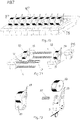
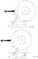
- Each mechanism M5 of the bank of mechanisms B5 according to the invention depicted in Figs. 49 to 60 , is a reversible mechanism, i.e. it allows the selection of the travelling interdiction direction.
- 50 to 56 consists of a mobile piece 20, having a removable spike 19; a mobile roller 23 mounted on a shaft 23' in said mobile piece 20; a shaft 3 common to the other mechanisms M5, housed in the other cells of the bank of mechanisms B5 supports said mobile piece 20, two stops 15 arranged on the opposite inner sides of the intermediate vertical wall P5 and which surfaces provided with a damping and noise reduction element serve as a stop to said roller 23; two control devices each consisting of one bush 8 having peripherally and centrally a cogged recess; a manual driver 7 consisting of a screw acting on said bush 8 cogged recess and a motorized actuator 11, consisting of one engine that operates a head 9 of a screw through a gear wheel 10, the screw in turn acting on said bush 8 cogged recess; the common shaft 5 crossing said vertical walls R5, P5 and T5 through respective holes, on said common shaft 5 and joined to it by a indentation being mounted respectively the bushes 8, 13 and the mobile stops 15', which surfaces, provided with a damping and noise
- the bank of mechanisms B5 operates as follows:
- Figs. 61 and 62 show a variant of the mobile roller 23 assembly, in which the shaft 23' is mounted in a slot and is pressed upwards by a spring 23", which causes the spike 19 stays hidden when the mobile roller 23 is not biased in the downward direction.
- a tyre R see Fig. 62
- the spike protrudes and punctures the tyre R.
- the bank of mechanisms B6 operates as follows:
- Each mechanism M7 of the bank of mechanisms B7 depicted in Fig. 70 which is depicted in more detail in Figs. 71 and 72 consists of a mobile piece 20 having a fixed spike 19; a mobile roller 23 mounted on a shaft 23' in said mobile piece 20; a return spring 31; a shaft 3 common to the other mechanisms M7 housed in the other cells of the bank of mechanisms B7 supports said mobile piece 20 and said return spring 31; a stop 16 arranged on the inner side of the vertical wall P6 near said common shaft 3 and which surface provided or not with a damping and noise reduction element serves as a stop to said mobile piece 20; and said mobile piece 20 having in its lower portion central zone a slot where is housed said spring 31 which end keeps the mobile piece under pressure abutted against the stop 16.
- the bank of mechanisms B7 operates as follows:
- Figs. 77 and 78 show practical implementation examples of the bank of mechanisms exemplified in the figures above.
- the invention devices may be associated with any other electronic devices for detecting vehicles, which may include at least one traffic light of red lights and where appropriate.
- the devices according to the invention when provided with motorized control may be controlled by remote control, which in turn can be activated by the frequency used by emergency services and fire brigades or the police to allow the use, for example, by ambulances, fire brigades vehicles or police vehicles to roads accessing highways safely in the unauthorized direction, i.e. the wrong direction.
Landscapes
- Engineering & Computer Science (AREA)
- Architecture (AREA)
- Civil Engineering (AREA)
- Structural Engineering (AREA)
- Tires In General (AREA)
- Road Paving Structures (AREA)
- Road Paving Machines (AREA)
- Refuge Islands, Traffic Blockers, Or Guard Fence (AREA)
- Road Signs Or Road Markings (AREA)
Applications Claiming Priority (2)
| Application Number | Priority Date | Filing Date | Title |
|---|---|---|---|
| PT104013A PT104013B (pt) | 2008-04-04 | 2008-04-04 | Dispositivo para impedir a circulação de veículos |
| PCT/PT2009/000016 WO2009123485A1 (en) | 2008-04-04 | 2009-03-31 | Device for halting vehicle traffic |
Publications (2)
| Publication Number | Publication Date |
|---|---|
| EP2286032A1 EP2286032A1 (en) | 2011-02-23 |
| EP2286032B1 true EP2286032B1 (en) | 2016-12-14 |
Family
ID=40823417
Family Applications (1)
| Application Number | Title | Priority Date | Filing Date |
|---|---|---|---|
| EP09728888.0A Not-in-force EP2286032B1 (en) | 2008-04-04 | 2009-03-31 | Device for halting vehicle traffic |
Country Status (9)
| Country | Link |
|---|---|
| US (1) | US8562244B2 (pt) |
| EP (1) | EP2286032B1 (pt) |
| AR (1) | AR071576A1 (pt) |
| BR (1) | BRPI0906534A2 (pt) |
| CA (1) | CA2719359C (pt) |
| PT (1) | PT104013B (pt) |
| SA (1) | SA109300209B1 (pt) |
| WO (1) | WO2009123485A1 (pt) |
| ZA (1) | ZA201006948B (pt) |
Families Citing this family (19)
| Publication number | Priority date | Publication date | Assignee | Title |
|---|---|---|---|---|
| SI23220A (sl) | 2009-11-09 | 2011-05-31 | Uroš LAJOVIC | Naprava za preprečevanje vožnje vozil v prepovedani smeri |
| GB2479722B (en) | 2010-04-19 | 2015-08-05 | Heald Technologies Ltd | Security barrier |
| US8506203B2 (en) * | 2011-03-23 | 2013-08-13 | Dynasystems, LLC | Tire deflation device |
| US8395662B1 (en) * | 2011-12-05 | 2013-03-12 | Adel Jumah Alabdeen | Aviation emergency response system |
| ES2435467B1 (es) * | 2013-06-17 | 2014-07-29 | European Security Fencing S.L | Barrera de seguridad anti-intrusión de vehiculos |
| US12161527B2 (en) | 2014-03-07 | 2024-12-10 | Quadric Biomed, Llc | Dental implant with improved trans-gingival emergence profile |
| US20180222741A1 (en) * | 2015-07-08 | 2018-08-09 | Dops Project Pty Ltd | Vehicle drive away prevention |
| LU92772B1 (en) * | 2015-07-13 | 2017-01-31 | Abu Al Rubb Khalil Mahmoud | Traffic calming device |
| US9573573B1 (en) * | 2015-12-18 | 2017-02-21 | Michael Hickling | Errant vehicle interdiction device |
| JP2017193953A (ja) * | 2016-04-15 | 2017-10-26 | テック大洋工業株式会社 | 逆走の注意喚起装置 |
| USD889297S1 (en) * | 2018-03-30 | 2020-07-07 | Jing Nan Traffic Engineering Co., Ltd. | Road reflector base |
| CN108824264B (zh) * | 2018-08-06 | 2024-05-07 | 孙博文 | 便携式单轮阻车器 |
| KR102060938B1 (ko) * | 2018-08-24 | 2019-12-31 | 박지연 | 차량 역주행 방지장치 |
| US20200181859A1 (en) * | 2018-12-11 | 2020-06-11 | Roadshark International Inc. | Counterbalanced Inground Traffic Control Device |
| US20220233280A1 (en) | 2019-05-24 | 2022-07-28 | Grant Dental Technology Corporation | Dental implant system |
| EP3997272B1 (en) * | 2019-07-10 | 2024-11-13 | Viken Detection Corporation | Vehicle barrier with transfer force deployment |
| CN113089542B (zh) * | 2020-01-08 | 2022-07-08 | 青海民族大学 | 一种潮汐道路逆止路障 |
| CN112049044B (zh) * | 2020-09-05 | 2021-06-01 | 深圳市宝晨物业管理有限公司 | 一种停车场阻拦排水机构 |
| US20230175215A1 (en) * | 2021-12-03 | 2023-06-08 | Continental Automotive Gmbh | Spike barrier detection vehicular system and method |
Family Cites Families (17)
| Publication number | Priority date | Publication date | Assignee | Title |
|---|---|---|---|---|
| US1563637A (en) * | 1925-02-24 | 1925-12-01 | Paul A Lundblad | Railway-crossing guard |
| US2762145A (en) * | 1953-04-27 | 1956-09-11 | Orville W Rupe | One-way-travel barrier |
| US3325782A (en) * | 1965-01-11 | 1967-06-13 | Der Nicholas | Traffic control system |
| US3783558A (en) * | 1973-01-17 | 1974-01-08 | Auto Parks Inc | Directional traffic control devices |
| US4016679A (en) * | 1975-05-19 | 1977-04-12 | Rusco Industries, Inc. | Traffic control apparatus |
| US4097170A (en) * | 1977-02-18 | 1978-06-27 | Dickinson Harry D | Modular traffic controller |
| US4101235A (en) * | 1977-06-27 | 1978-07-18 | Nelson Donald F | Parking lot exit control means |
| US4158514A (en) * | 1978-06-16 | 1979-06-19 | Dickinson Harry D | Safety traffic controller |
| US4318079A (en) * | 1980-06-19 | 1982-03-02 | Dickinson Harry D | Motorized tire barrier and signal barrier traffic-way controller |
| US4325651A (en) * | 1980-10-14 | 1982-04-20 | Alexander Szegi | Protected traffic controller spikes |
| FR2522036A1 (fr) * | 1982-02-25 | 1983-08-26 | Bourdeaud Hui Joel | Herse retractable (systeme contrepoids) |
| DE3631315A1 (de) * | 1986-09-15 | 1988-04-07 | Horst Eggl | Vorrichtung zum sperren von durch- und einfahrten |
| US5192158A (en) * | 1991-03-11 | 1993-03-09 | Park N' Shade | Apparatus for controlling the direction of vehicular traffic movement |
| US5288164A (en) * | 1992-01-07 | 1994-02-22 | Nasatka Ralph G | Combined vehicle barrier |
| US5733063A (en) * | 1996-09-06 | 1998-03-31 | John C. Gort | Apparatus for controlling vehicular traffic flow past a control point |
| US6045293A (en) * | 1998-02-27 | 2000-04-04 | Dickinson; Harry D. | Driver intimidating person friendly tire destructive trafficway controller |
| US7025526B2 (en) * | 2003-03-11 | 2006-04-11 | Pmg, Inc. | Portable traffic control device |
-
2008
- 2008-04-04 PT PT104013A patent/PT104013B/pt active IP Right Grant
-
2009
- 2009-03-31 WO PCT/PT2009/000016 patent/WO2009123485A1/en not_active Ceased
- 2009-03-31 EP EP09728888.0A patent/EP2286032B1/en not_active Not-in-force
- 2009-03-31 CA CA2719359A patent/CA2719359C/en not_active Expired - Fee Related
- 2009-03-31 US US12/936,369 patent/US8562244B2/en not_active Expired - Fee Related
- 2009-03-31 BR BRPI0906534-2A patent/BRPI0906534A2/pt not_active IP Right Cessation
- 2009-04-01 AR ARP090101174A patent/AR071576A1/es unknown
- 2009-04-04 SA SA109300209A patent/SA109300209B1/ar unknown
-
2010
- 2010-09-29 ZA ZA2010/06948A patent/ZA201006948B/en unknown
Also Published As
| Publication number | Publication date |
|---|---|
| ZA201006948B (en) | 2011-06-29 |
| BRPI0906534A2 (pt) | 2015-06-30 |
| US20110033233A1 (en) | 2011-02-10 |
| US8562244B2 (en) | 2013-10-22 |
| PT104013A (pt) | 2009-10-06 |
| AR071576A1 (es) | 2010-06-30 |
| WO2009123485A1 (en) | 2009-10-08 |
| PT104013B (pt) | 2010-09-02 |
| CA2719359C (en) | 2016-11-08 |
| SA109300209B1 (ar) | 2012-11-24 |
| WO2009123485A4 (en) | 2009-11-19 |
| EP2286032A1 (en) | 2011-02-23 |
| CA2719359A1 (en) | 2009-10-08 |
Similar Documents
| Publication | Publication Date | Title |
|---|---|---|
| EP2286032B1 (en) | Device for halting vehicle traffic | |
| US5466088A (en) | Vehicle barrier having a pivotal vehicle barricade and a cooperating pivotal signal barrier | |
| JP5264554B2 (ja) | 車両通行制御装置 | |
| CA1159538A (en) | Electrically controlled safety mechanism for highway exit ramp | |
| EP3346055A1 (en) | Collapsible barricade apparatus | |
| US4554695A (en) | Vehicular road block | |
| WO2004067846A2 (en) | Vehicle arresting installation | |
| US20050220536A1 (en) | Bollard and cable vehicle barrier | |
| US6045293A (en) | Driver intimidating person friendly tire destructive trafficway controller | |
| WO2020070901A1 (ja) | 移動体阻止器及び拘束器 | |
| KR101852515B1 (ko) | 회전형 가드레일 | |
| KR100661758B1 (ko) | 튜브식 차단바를 구비한 안전차단장치 | |
| US12577744B2 (en) | Device for thwarting vehicular stunts | |
| KR200390566Y1 (ko) | 자동차 충격완충장치 | |
| BE1025824B1 (nl) | Wegversperringsinrichting | |
| KR100804736B1 (ko) | 자동차 충격완충장치 | |
| WO2001092642A1 (en) | Barriers | |
| KR100701059B1 (ko) | 차량진입을 선택적으로 차단하는 횡단보도의 도로구조 | |
| KR200313288Y1 (ko) | 도로의 2중 충격흡수 가드레일 | |
| KR20100076286A (ko) | 자동과속방지차단장치 | |
| JP2007046340A (ja) | 車両侵入防止装置 | |
| GB2327696A (en) | A Tyre Deflation Device | |
| KR20120108349A (ko) | 차량 통행 차단장치 | |
| KR100466888B1 (ko) | 도로의 충격흡수용 회전식 경계석 구조 | |
| ES2360321B1 (es) | Dispositivo automatico para control del sentido de circulacion de vehiculos. |
Legal Events
| Date | Code | Title | Description |
|---|---|---|---|
| PUAI | Public reference made under article 153(3) epc to a published international application that has entered the european phase |
Free format text: ORIGINAL CODE: 0009012 |
|
| 17P | Request for examination filed |
Effective date: 20101013 |
|
| AK | Designated contracting states |
Kind code of ref document: A1 Designated state(s): AT BE BG CH CY CZ DE DK EE ES FI FR GB GR HR HU IE IS IT LI LT LU LV MC MK MT NL NO PL PT RO SE SI SK TR |
|
| AX | Request for extension of the european patent |
Extension state: AL BA RS |
|
| DAX | Request for extension of the european patent (deleted) | ||
| 17Q | First examination report despatched |
Effective date: 20160111 |
|
| GRAP | Despatch of communication of intention to grant a patent |
Free format text: ORIGINAL CODE: EPIDOSNIGR1 |
|
| INTG | Intention to grant announced |
Effective date: 20160704 |
|
| GRAS | Grant fee paid |
Free format text: ORIGINAL CODE: EPIDOSNIGR3 |
|
| STAA | Information on the status of an ep patent application or granted ep patent |
Free format text: STATUS: GRANT OF PATENT IS INTENDED |
|
| GRAA | (expected) grant |
Free format text: ORIGINAL CODE: 0009210 |
|
| STAA | Information on the status of an ep patent application or granted ep patent |
Free format text: STATUS: THE PATENT HAS BEEN GRANTED |
|
| AK | Designated contracting states |
Kind code of ref document: B1 Designated state(s): AT BE BG CH CY CZ DE DK EE ES FI FR GB GR HR HU IE IS IT LI LT LU LV MC MK MT NL NO PL PT RO SE SI SK TR |
|
| REG | Reference to a national code |
Ref country code: GB Ref legal event code: FG4D |
|
| REG | Reference to a national code |
Ref country code: CH Ref legal event code: EP |
|
| REG | Reference to a national code |
Ref country code: IE Ref legal event code: FG4D |
|
| REG | Reference to a national code |
Ref country code: AT Ref legal event code: REF Ref document number: 853705 Country of ref document: AT Kind code of ref document: T Effective date: 20170115 |
|
| REG | Reference to a national code |
Ref country code: DE Ref legal event code: R096 Ref document number: 602009043055 Country of ref document: DE |
|
| PG25 | Lapsed in a contracting state [announced via postgrant information from national office to epo] |
Ref country code: LV Free format text: LAPSE BECAUSE OF FAILURE TO SUBMIT A TRANSLATION OF THE DESCRIPTION OR TO PAY THE FEE WITHIN THE PRESCRIBED TIME-LIMIT Effective date: 20161214 |
|
| REG | Reference to a national code |
Ref country code: FR Ref legal event code: PLFP Year of fee payment: 9 |
|
| REG | Reference to a national code |
Ref country code: LT Ref legal event code: MG4D |
|
| REG | Reference to a national code |
Ref country code: NL Ref legal event code: MP Effective date: 20161214 |
|
| PG25 | Lapsed in a contracting state [announced via postgrant information from national office to epo] |
Ref country code: LT Free format text: LAPSE BECAUSE OF FAILURE TO SUBMIT A TRANSLATION OF THE DESCRIPTION OR TO PAY THE FEE WITHIN THE PRESCRIBED TIME-LIMIT Effective date: 20161214 Ref country code: SE Free format text: LAPSE BECAUSE OF FAILURE TO SUBMIT A TRANSLATION OF THE DESCRIPTION OR TO PAY THE FEE WITHIN THE PRESCRIBED TIME-LIMIT Effective date: 20161214 Ref country code: NO Free format text: LAPSE BECAUSE OF FAILURE TO SUBMIT A TRANSLATION OF THE DESCRIPTION OR TO PAY THE FEE WITHIN THE PRESCRIBED TIME-LIMIT Effective date: 20170314 |
|
| REG | Reference to a national code |
Ref country code: AT Ref legal event code: MK05 Ref document number: 853705 Country of ref document: AT Kind code of ref document: T Effective date: 20161214 |
|
| PG25 | Lapsed in a contracting state [announced via postgrant information from national office to epo] |
Ref country code: HR Free format text: LAPSE BECAUSE OF FAILURE TO SUBMIT A TRANSLATION OF THE DESCRIPTION OR TO PAY THE FEE WITHIN THE PRESCRIBED TIME-LIMIT Effective date: 20161214 Ref country code: FI Free format text: LAPSE BECAUSE OF FAILURE TO SUBMIT A TRANSLATION OF THE DESCRIPTION OR TO PAY THE FEE WITHIN THE PRESCRIBED TIME-LIMIT Effective date: 20161214 |
|
| PG25 | Lapsed in a contracting state [announced via postgrant information from national office to epo] |
Ref country code: NL Free format text: LAPSE BECAUSE OF FAILURE TO SUBMIT A TRANSLATION OF THE DESCRIPTION OR TO PAY THE FEE WITHIN THE PRESCRIBED TIME-LIMIT Effective date: 20161214 |
|
| PG25 | Lapsed in a contracting state [announced via postgrant information from national office to epo] |
Ref country code: RO Free format text: LAPSE BECAUSE OF FAILURE TO SUBMIT A TRANSLATION OF THE DESCRIPTION OR TO PAY THE FEE WITHIN THE PRESCRIBED TIME-LIMIT Effective date: 20161214 Ref country code: EE Free format text: LAPSE BECAUSE OF FAILURE TO SUBMIT A TRANSLATION OF THE DESCRIPTION OR TO PAY THE FEE WITHIN THE PRESCRIBED TIME-LIMIT Effective date: 20161214 Ref country code: SK Free format text: LAPSE BECAUSE OF FAILURE TO SUBMIT A TRANSLATION OF THE DESCRIPTION OR TO PAY THE FEE WITHIN THE PRESCRIBED TIME-LIMIT Effective date: 20161214 Ref country code: IS Free format text: LAPSE BECAUSE OF FAILURE TO SUBMIT A TRANSLATION OF THE DESCRIPTION OR TO PAY THE FEE WITHIN THE PRESCRIBED TIME-LIMIT Effective date: 20170414 Ref country code: CZ Free format text: LAPSE BECAUSE OF FAILURE TO SUBMIT A TRANSLATION OF THE DESCRIPTION OR TO PAY THE FEE WITHIN THE PRESCRIBED TIME-LIMIT Effective date: 20161214 |
|
| PG25 | Lapsed in a contracting state [announced via postgrant information from national office to epo] |
Ref country code: PT Free format text: LAPSE BECAUSE OF FAILURE TO SUBMIT A TRANSLATION OF THE DESCRIPTION OR TO PAY THE FEE WITHIN THE PRESCRIBED TIME-LIMIT Effective date: 20170414 Ref country code: ES Free format text: LAPSE BECAUSE OF FAILURE TO SUBMIT A TRANSLATION OF THE DESCRIPTION OR TO PAY THE FEE WITHIN THE PRESCRIBED TIME-LIMIT Effective date: 20161214 Ref country code: BE Free format text: LAPSE BECAUSE OF FAILURE TO SUBMIT A TRANSLATION OF THE DESCRIPTION OR TO PAY THE FEE WITHIN THE PRESCRIBED TIME-LIMIT Effective date: 20161214 Ref country code: AT Free format text: LAPSE BECAUSE OF FAILURE TO SUBMIT A TRANSLATION OF THE DESCRIPTION OR TO PAY THE FEE WITHIN THE PRESCRIBED TIME-LIMIT Effective date: 20161214 Ref country code: PL Free format text: LAPSE BECAUSE OF FAILURE TO SUBMIT A TRANSLATION OF THE DESCRIPTION OR TO PAY THE FEE WITHIN THE PRESCRIBED TIME-LIMIT Effective date: 20161214 Ref country code: IT Free format text: LAPSE BECAUSE OF FAILURE TO SUBMIT A TRANSLATION OF THE DESCRIPTION OR TO PAY THE FEE WITHIN THE PRESCRIBED TIME-LIMIT Effective date: 20161214 Ref country code: BG Free format text: LAPSE BECAUSE OF FAILURE TO SUBMIT A TRANSLATION OF THE DESCRIPTION OR TO PAY THE FEE WITHIN THE PRESCRIBED TIME-LIMIT Effective date: 20170314 |
|
| REG | Reference to a national code |
Ref country code: DE Ref legal event code: R097 Ref document number: 602009043055 Country of ref document: DE |
|
| PLBE | No opposition filed within time limit |
Free format text: ORIGINAL CODE: 0009261 |
|
| STAA | Information on the status of an ep patent application or granted ep patent |
Free format text: STATUS: NO OPPOSITION FILED WITHIN TIME LIMIT |
|
| REG | Reference to a national code |
Ref country code: CH Ref legal event code: PL |
|
| REG | Reference to a national code |
Ref country code: DE Ref legal event code: R082 Ref document number: 602009043055 Country of ref document: DE |
|
| 26N | No opposition filed |
Effective date: 20170915 |
|
| GBPC | Gb: european patent ceased through non-payment of renewal fee |
Effective date: 20170331 |
|
| PG25 | Lapsed in a contracting state [announced via postgrant information from national office to epo] |
Ref country code: MC Free format text: LAPSE BECAUSE OF FAILURE TO SUBMIT A TRANSLATION OF THE DESCRIPTION OR TO PAY THE FEE WITHIN THE PRESCRIBED TIME-LIMIT Effective date: 20161214 Ref country code: DK Free format text: LAPSE BECAUSE OF FAILURE TO SUBMIT A TRANSLATION OF THE DESCRIPTION OR TO PAY THE FEE WITHIN THE PRESCRIBED TIME-LIMIT Effective date: 20161214 |
|
| REG | Reference to a national code |
Ref country code: IE Ref legal event code: MM4A |
|
| PG25 | Lapsed in a contracting state [announced via postgrant information from national office to epo] |
Ref country code: LU Free format text: LAPSE BECAUSE OF NON-PAYMENT OF DUE FEES Effective date: 20170331 |
|
| PG25 | Lapsed in a contracting state [announced via postgrant information from national office to epo] |
Ref country code: SI Free format text: LAPSE BECAUSE OF FAILURE TO SUBMIT A TRANSLATION OF THE DESCRIPTION OR TO PAY THE FEE WITHIN THE PRESCRIBED TIME-LIMIT Effective date: 20161214 Ref country code: IE Free format text: LAPSE BECAUSE OF NON-PAYMENT OF DUE FEES Effective date: 20170331 Ref country code: CH Free format text: LAPSE BECAUSE OF NON-PAYMENT OF DUE FEES Effective date: 20170331 Ref country code: LI Free format text: LAPSE BECAUSE OF NON-PAYMENT OF DUE FEES Effective date: 20170331 Ref country code: GB Free format text: LAPSE BECAUSE OF NON-PAYMENT OF DUE FEES Effective date: 20170331 |
|
| REG | Reference to a national code |
Ref country code: FR Ref legal event code: PLFP Year of fee payment: 10 |
|
| PG25 | Lapsed in a contracting state [announced via postgrant information from national office to epo] |
Ref country code: MT Free format text: LAPSE BECAUSE OF NON-PAYMENT OF DUE FEES Effective date: 20170331 |
|
| PGFP | Annual fee paid to national office [announced via postgrant information from national office to epo] |
Ref country code: DE Payment date: 20190220 Year of fee payment: 11 |
|
| PGFP | Annual fee paid to national office [announced via postgrant information from national office to epo] |
Ref country code: FR Payment date: 20190219 Year of fee payment: 11 |
|
| PG25 | Lapsed in a contracting state [announced via postgrant information from national office to epo] |
Ref country code: HU Free format text: LAPSE BECAUSE OF FAILURE TO SUBMIT A TRANSLATION OF THE DESCRIPTION OR TO PAY THE FEE WITHIN THE PRESCRIBED TIME-LIMIT; INVALID AB INITIO Effective date: 20090331 |
|
| PG25 | Lapsed in a contracting state [announced via postgrant information from national office to epo] |
Ref country code: CY Free format text: LAPSE BECAUSE OF NON-PAYMENT OF DUE FEES Effective date: 20161214 |
|
| PG25 | Lapsed in a contracting state [announced via postgrant information from national office to epo] |
Ref country code: MK Free format text: LAPSE BECAUSE OF FAILURE TO SUBMIT A TRANSLATION OF THE DESCRIPTION OR TO PAY THE FEE WITHIN THE PRESCRIBED TIME-LIMIT Effective date: 20161214 |
|
| PG25 | Lapsed in a contracting state [announced via postgrant information from national office to epo] |
Ref country code: TR Free format text: LAPSE BECAUSE OF FAILURE TO SUBMIT A TRANSLATION OF THE DESCRIPTION OR TO PAY THE FEE WITHIN THE PRESCRIBED TIME-LIMIT Effective date: 20161214 |
|
| PG25 | Lapsed in a contracting state [announced via postgrant information from national office to epo] |
Ref country code: GR Free format text: LAPSE BECAUSE OF FAILURE TO SUBMIT A TRANSLATION OF THE DESCRIPTION OR TO PAY THE FEE WITHIN THE PRESCRIBED TIME-LIMIT Effective date: 20161214 |
|
| REG | Reference to a national code |
Ref country code: DE Ref legal event code: R119 Ref document number: 602009043055 Country of ref document: DE |
|
| PG25 | Lapsed in a contracting state [announced via postgrant information from national office to epo] |
Ref country code: DE Free format text: LAPSE BECAUSE OF NON-PAYMENT OF DUE FEES Effective date: 20201001 Ref country code: FR Free format text: LAPSE BECAUSE OF NON-PAYMENT OF DUE FEES Effective date: 20200331 |