EP2286087B1 - Kryogene pumpe mit zinnantimonlegierungen und verfahren zu ihrer verwendung - Google Patents
Kryogene pumpe mit zinnantimonlegierungen und verfahren zu ihrer verwendung Download PDFInfo
- Publication number
- EP2286087B1 EP2286087B1 EP09755482.8A EP09755482A EP2286087B1 EP 2286087 B1 EP2286087 B1 EP 2286087B1 EP 09755482 A EP09755482 A EP 09755482A EP 2286087 B1 EP2286087 B1 EP 2286087B1
- Authority
- EP
- European Patent Office
- Prior art keywords
- stage
- heat exchanger
- cryogenic refrigerator
- regenerative heat
- refrigerator
- Prior art date
- Legal status (The legal status is an assumption and is not a legal conclusion. Google has not performed a legal analysis and makes no representation as to the accuracy of the status listed.)
- Active
Links
Images






Classifications
-
- F—MECHANICAL ENGINEERING; LIGHTING; HEATING; WEAPONS; BLASTING
- F25—REFRIGERATION OR COOLING; COMBINED HEATING AND REFRIGERATION SYSTEMS; HEAT PUMP SYSTEMS; MANUFACTURE OR STORAGE OF ICE; LIQUEFACTION SOLIDIFICATION OF GASES
- F25B—REFRIGERATION MACHINES, PLANTS OR SYSTEMS; COMBINED HEATING AND REFRIGERATION SYSTEMS; HEAT PUMP SYSTEMS
- F25B9/00—Compression machines, plants or systems, in which the refrigerant is air or other gas of low boiling point
-
- F—MECHANICAL ENGINEERING; LIGHTING; HEATING; WEAPONS; BLASTING
- F04—POSITIVE - DISPLACEMENT MACHINES FOR LIQUIDS; PUMPS FOR LIQUIDS OR ELASTIC FLUIDS
- F04B—POSITIVE-DISPLACEMENT MACHINES FOR LIQUIDS; PUMPS
- F04B37/00—Pumps having pertinent characteristics not provided for in, or of interest apart from, groups F04B25/00 - F04B35/00
- F04B37/06—Pumps having pertinent characteristics not provided for in, or of interest apart from, groups F04B25/00 - F04B35/00 for evacuating by thermal means
- F04B37/08—Pumps having pertinent characteristics not provided for in, or of interest apart from, groups F04B25/00 - F04B35/00 for evacuating by thermal means by condensing or freezing, e.g. cryogenic pumps
-
- F—MECHANICAL ENGINEERING; LIGHTING; HEATING; WEAPONS; BLASTING
- F04—POSITIVE - DISPLACEMENT MACHINES FOR LIQUIDS; PUMPS FOR LIQUIDS OR ELASTIC FLUIDS
- F04B—POSITIVE-DISPLACEMENT MACHINES FOR LIQUIDS; PUMPS
- F04B39/00—Component parts, details, or accessories, of pumps or pumping systems specially adapted for elastic fluids, not otherwise provided for in, or of interest apart from, groups F04B25/00 - F04B37/00
- F04B39/06—Cooling; Heating; Prevention of freezing
-
- F—MECHANICAL ENGINEERING; LIGHTING; HEATING; WEAPONS; BLASTING
- F04—POSITIVE - DISPLACEMENT MACHINES FOR LIQUIDS; PUMPS FOR LIQUIDS OR ELASTIC FLUIDS
- F04B—POSITIVE-DISPLACEMENT MACHINES FOR LIQUIDS; PUMPS
- F04B53/00—Component parts, details or accessories not provided for in, or of interest apart from, groups F04B1/00 - F04B23/00 or F04B39/00 - F04B47/00
- F04B53/08—Cooling; Heating; Preventing freezing
-
- F—MECHANICAL ENGINEERING; LIGHTING; HEATING; WEAPONS; BLASTING
- F25—REFRIGERATION OR COOLING; COMBINED HEATING AND REFRIGERATION SYSTEMS; HEAT PUMP SYSTEMS; MANUFACTURE OR STORAGE OF ICE; LIQUEFACTION SOLIDIFICATION OF GASES
- F25B—REFRIGERATION MACHINES, PLANTS OR SYSTEMS; COMBINED HEATING AND REFRIGERATION SYSTEMS; HEAT PUMP SYSTEMS
- F25B9/00—Compression machines, plants or systems, in which the refrigerant is air or other gas of low boiling point
- F25B9/14—Compression machines, plants or systems, in which the refrigerant is air or other gas of low boiling point characterised by the cycle used, e.g. Stirling cycle
-
- F—MECHANICAL ENGINEERING; LIGHTING; HEATING; WEAPONS; BLASTING
- F25—REFRIGERATION OR COOLING; COMBINED HEATING AND REFRIGERATION SYSTEMS; HEAT PUMP SYSTEMS; MANUFACTURE OR STORAGE OF ICE; LIQUEFACTION SOLIDIFICATION OF GASES
- F25B—REFRIGERATION MACHINES, PLANTS OR SYSTEMS; COMBINED HEATING AND REFRIGERATION SYSTEMS; HEAT PUMP SYSTEMS
- F25B2309/00—Gas cycle refrigeration machines
- F25B2309/003—Gas cycle refrigeration machines characterised by construction or composition of the regenerator
-
- F—MECHANICAL ENGINEERING; LIGHTING; HEATING; WEAPONS; BLASTING
- F25—REFRIGERATION OR COOLING; COMBINED HEATING AND REFRIGERATION SYSTEMS; HEAT PUMP SYSTEMS; MANUFACTURE OR STORAGE OF ICE; LIQUEFACTION SOLIDIFICATION OF GASES
- F25B—REFRIGERATION MACHINES, PLANTS OR SYSTEMS; COMBINED HEATING AND REFRIGERATION SYSTEMS; HEAT PUMP SYSTEMS
- F25B2309/00—Gas cycle refrigeration machines
- F25B2309/14—Compression machines, plants or systems characterised by the cycle used
- F25B2309/1415—Pulse-tube cycles characterised by regenerator details
Definitions
- cryogenic vacuum pumps generally follow a common design concept.
- a low temperature array usually operating in the range of 4 to 25 K, is the primary pumping surface. This surface is surrounded by a higher temperature radiation shield, usually operated in the temperature range of 60 to 130 K.
- the radiation shield protects the lower temperature array from radiated heat.
- the radiation shield generally includes a housing which is closed except at an opening where a frontal array is positioned between the primary pumping surface and a work chamber to be evacuated.
- high boiling point gases such as water vapor are condensed on the frontal array.
- Lower boiling point gases pass through that array and into the volume within the radiation shield and condense on the lower temperature array.
- a surface coated with an adsorbent such as charcoal or a molecular sieve operating at or below the temperature of the colder array may also be provided in this volume to remove the very low boiling point gases such as hydrogen.
- the cooler In systems cooled by closed-cycle cryocoolers, the cooler is typically a two- stage refrigerator having a cold finger which extends through the rear or side of the radiation shield.
- High pressure helium refrigerant is generally delivered to the refrigerator through high pressure lines from a compressor assembly.
- Electrical power to a displacer drive motor in the cooler is usually also delivered through the compressor or a controller assembly.
- the radiation shield is connected to a heat sink, or cold station, at the coldest end of the first stage of the refrigerator.
- the shield surrounds the second stage cryopanel in such a way as to protect it from radiant heat.
- the frontal array is cooled by the first stage heat sink through its attachment to the radiation shield or, as disclosed in U.S. Pat. No. 4,356,701 , through thermal struts.
- the coldest end of the second, coldest stage of the cryocooler is at the tip of the cold finger.
- the primary pumping surface, or cryopanel is connected to a heat sink at this coldest end of the second stage.
- This cryopanel may be a simple metal plate or cup, or it may be an array of metal baffles arranged around and connected to the second-stage heat sink.
- This second stage cryopanel also supports the low temperature adsorbent.
- Lead is a poisonous metal that can damage nervous systems, especially in young children, and cause blood and brain disorders. Long term exposure to lead or its salts (especially soluble salts or the strong oxidant Pb02) can cause nephropathy, and colic-like abdominal pains. Therefore, the use of lead in products is now either banned, restricted or undesirable.
- regenerative materials too, have disadvantages.
- rare- earth containing intermetallic compounds are extremely expensive.
- intermetallic materials are harder and more brittle than metal compounds, and, therefore, are difficult to produce in the geometries needed for the regenerative heat exchangers in cryogenic refrigerators. These materials also have relatively poor performance because they can easily disintegrate into powder when exposed to repeated mechanical shocks during normal refrigerator operation.
- Bismuth is another metal with high volumetric heat capacity, but it is very expensive, brittle, and difficult to fabricate into the spherical shape needed for regenerator material.
- Bismuth can also disintegrate into powder like the intermetallic compounds, with the added disadvantage that bismuth powder is highly flammable and reactive with aluminum and air.
- Aluminum is a common material of construction in cryogenic refrigerators and thus the powder may react when the refrigerator is disassembled in air.
- JP 2005 075963 discloses an ultra cold cooling material made of bismuth or an alloy.
- WO2007/036729 discloses the use of a material of general formula (I); as a magnetocaloric material, wherein the material is orthorhombic and wherein: A is selected from Ni, Cr, Fe, Al, P, Se, Ga and Sb and mixtures thereof; - B is selected from Ge, Sn, Al, P, Se, Ga and Sb and mixtures thereof; C is selected from Ni, Cr, Fe, Al, P, Se, Ga and Sb and mixtures thereof; x, y and z are the same or different and are numbers in the range 0 to 0.2; and u and v are the same or different and are numbers in the range 0.5 to 1.5.
- US6467277 discloses a cold accumulating material comprising a number of magnetic particles mainly composed of oxide.
- US6318090 discloses a cryocooler with a regenerator comprising one or more regenerator components, which are ductile and oxidation resistant, including a rare earth metal, an alloy of two or more rare earth metals, an alloy of a rare earth metal with a non-rare earth metal, and an alloy of a rare earth metal with at least one interstitial element
- the invention includes a cryogenic refrigerator that comprises a regenerative heat exchanger material in thermal contact with a working gas, said cryogenic refrigerator including at least one cooling stage including the regenerative heat exchanger material, the regenerative heat exchanger material comprising a ternary alloy following a general formula Sn-Sb-M, wherein, M is at least one element selected from the group consisting of Bi, Ag, Ge, Cu, La, Mg, Mn, Nd, Ni, Pd, Pt, K, Rh, Sm, Se, S, Y, Fe, In, Al, Ce, Dy, Cd, Ti, Au, P, Pr, Yb and Zn, the Sn-Sb-M alloy material comprising from about 0.01 % to about 40 % of M by weight, from about 0.1 % to about 43 % of Sb by weight, and from about 50 % to about 99.5 % of Sn by weight.
- M is at least one element selected from the group consisting of Bi, Ag, Ge, Cu, La, Mg, M
- the cryogenic refrigerator is a pulse tube cryogenic refrigerator.
- the cryogenic refrigerator is a Stirling cryogenic refrigerator.
- the cryogenic refrigerator is a Gifford-McMahon cryogenic refrigerator.
- the cryogenic refrigerator includes a cryopump that includes at least one cryopanel cooled by the refrigerator and adapted to condense or adsorb gases.
- the cooling stage includes at least two layers of regenerative heat exchanger material.
- the cooling stage further includes a cold station in direct thermal contact with the working gas.
- At least one layer includes a Sn-Sb-M alloy, and at least one layer includes at least one rare earth element. In certain other embodiments, at least one layer includes a Sn-Sb-M alloy, and at least one layer includes a rare earth intermetallic compound of one or more rare earth elements with a non-rare earth metal. In yet other embodiments, at least one layer includes a Sn -Sb-M alloy, and at least one layer includes a solid solution alloy of rare earth elements. In a specific embodiment, the Sn-Sb-M alloy includes substantially spherical Sn-Sb-M particulates, in a diameter range of between about 0.01 mm and about 3 mm.
- the cryopump comprises a regenerative heat exchanger material that includes an Sn-Sb-M alloy.
- M can include at least one element selected from the group consisting of Bi, Ag, Ge, Cu, La, Mg, Mn, Nd, Ni, Pd, Pt, K, Rh, Sm, Se, S, Y, Fe, In, Cd, Ti, Al, Ce, Dy, Au, P, Pr, Yb, and Zn, from about 0.01 % to about 40 % of M by weight, from about 0.1 % to about 43 % of Sb by weight, and from about 50 % to about 99.5 % of Sn by weight.
- the invention includes a cryopump that comprises a Gifford-McMahon cryogenic refrigerator that includes a reciprocating displacer within a cryogenic refrigerator with first and second coaxial stages, the displacer being driven in reciprocating motion alternately compressing and expanding a working gas adapted to be a cryogenic refrigerant, a regenerative heat exchanger material in the displacer in thermal contact with the working gas, the regenerative heat exchanger material an Sn-Sb-M alloy.
- a cryopump that comprises a Gifford-McMahon cryogenic refrigerator that includes a reciprocating displacer within a cryogenic refrigerator with first and second coaxial stages, the displacer being driven in reciprocating motion alternately compressing and expanding a working gas adapted to be a cryogenic refrigerant, a regenerative heat exchanger material in the displacer in thermal contact with the working gas, the regenerative heat exchanger material an Sn-Sb-M alloy.
- M can include at least one element selected from the group consisting of Bi, Ag, Ge, Cu, La, Mg, Mn, Nd, Ni, Pd, Pt, K, Rh, Sm, Se, S, Y, Fe, In, Cd, Ti, Al, Ce, Dy, Au, P, Pr, Yb, and Zn, from about 0.01 % to about 40 % ofM by weight, from about 0.1 % to about 43 % of Sb by weight, and from about 50 % to about 99.5 % of Sn by weight.
- the invention includes a cryopump that comprises a pulse tube cryogenic refrigerator that includes a buffer tank configured to contain a volume of a working gas adapted to be a cryogenic refrigerant, a first heat exchange region in fluid communication with the buffer tank, a pulse tube in fluid communication with the first heat exchange region, configured to transmit a gas pressure wave along the pulse tube, a second heat exchange region in fluid communication with the pulse tube, a cavity in fluid communication with the second heat exchange region, the cavity containing a regenerative heat exchanger material in thermal contact with the working gas, the regenerative heat exchanger material includes an Sn-Sb-M alloy.
- M can include at least one element selected from the group consisting of Bi, Ag, Ge, Cu, La, Mg, Mn, Nd, Ni, Pd, Pt, K, Rh, Sm, Se, S, Y, Fe, In, Cd, Ti, Al, Ce, Dy, Au, P, Pr, Yb, and Zn, from about 0.01 % to about 40 % of M by weight, from about 0.1 % to about 43 % of Sb by weight, and from about 50 % to about 99.5 % of Sn by weight.
- the method comprises reciprocating a displacer within a cold-accumulating unit of the cryopump.
- the displacer houses a regenerative heat exchanger material that includes a tin-antimony alloy.
- a working gas is introduced into the cold-accumulating unit under pressure, and then expanded by the displacer, thereby cooling the gas, which, in turn, cools the regenerative heat exchanger material.
- the working gas is helium.
- a method of operating a cryopump at cryogenic temperature comprises providing at least one cooling stage containing a working gas adapted to be a cryogenic refrigerant, and containing at least one cold station in thermal contact with the at least one cooling stage, and a regenerative heat exchanger material in thermal contact with the working gas, the regenerative heat exchanger material including a tin-antimony (Sn-Sb) alloy.
- the method further includes condensing or adsorbing gases on at least one cryopanel connected to the at least one cold station.
- the working gas is helium.
- the invention is advantageous in that it provides less hazardous and inexpensive regenerative heat exchanger materials including tin-antimony (Sn-Sb) alloys with high volumetric heat capacity that don't have the potential to degrade over time during operation and are able to be formed into the required geometry for cryogenic refrigerators.
- Cryogenic vacuum pumps that include regenerative heat exchanger materials of this invention as part of lead-free cryogenic refrigerators provide clean vacuum environments for semiconductor manufacturing and other electronics manufacturing processes.
- tin is generally non-toxic to humans, even upon uptake of small concentrations for a long period of time, and elemental tin rarely affects human health. As such, tin is an environmentally sensible substitute for lead as a regenerative heat exchanger material applied to cryogenic refrigerators in cryopumps, without significantly compromising volumetric heat capacity as shown in FIG. 1 .
- Tin has two allotropes at normal pressure and temperature: gray alpha (a)-tin and white beta ( ⁇ )-tin. Below 13.2 °C at equilibrium, it exists as ⁇ -tin, which has a cubic crystal structure similar to silicon and germanium. Gray tin has poor metallic properties; it is a dull-gray brittle material. When warmed above 13.2 °C at equilibrium, tin changes into white or ⁇ -tin, which is a ductile metal with a tetragonal structure. Alpha tin can cause undesirable effects in applications where the ductile properties of tin are important and the transformation results in powdering of the transformed material because of the stresses that result from the volume change associated with the transformation.
- ⁇ - tin to ⁇ -tin also occurs slowly when held for a long time below 13.2 °C. Incubation times for the formation of ⁇ -tin can range from months to more than a year.
- the transformation involves an incubation time in which the alpha phase nucleates at the surface, and a growth phase in which the alpha phase grows into the beta phase over time.
- the result can be a metallic surface of white tin that becomes covered with a gray powder which is easily rubbed off. This process is known as tin disease or tin pest.
- Regenerative heat exchanger materials made of gray or alpha tin are unsuited to be applied in cryogenic cycles, because the low temperature surfaces of cryopumps operate in the range of 4 to 70 K (-269 °C to -203 °C) and cycle between room temperature and the cold operating range for regular maintenance and regeneration.
- the transformation to gray tin is prevented by the addition of antimony (Sb), in sufficient quantity, forming an alloy of tin and antimony.
- Tin alloys containing one or more of lead and bismuth in sufficient quantities or in combination resulting in sufficient quantities will also eliminate the transformation to ⁇ -tin.
- additional elements to enhance properties such as volumetric heat capacity and ductility and minimize thermal conductivity may be included as long as the minimum amount of the inhibiting element is included in the alloy.
- alloying elements include but are not limited to: In, Ag, Au, Cd, Ti, Ni, Bi, Ge, Cu, Mg, Mn, Pd, Pt, K, Rh, Se, S, Y, Fe, Al, P, Yb, Zn, and the rare-earth elements.
- the regenerative heat exchanger material can be a ternary alloy following the general formula Sn-Sb-M, wherein M is an element selected from the group consisting of Bi, Ag, Ge, Cu, La, Mg, Mn, Nd, Ni, Pd, Pt, K, Rh, Sm, Se, S, Y, Fe, In, Al, Ce, Dy, Cd, Ti, Au, P, Pr, Yb, Er, Ho, Gd, and Zn.
- the Sn-Sb-M alloy material can include from about 0.01 % to about 40 % of M by weight, from about 0.1 % to about 43 % of Sb by weight, and from about 50 % to about 99.5 % of Sn by weight.
- the regenerative heat exchanger materials of the present invention are comprised of spheres having substantially uniform diameters, in order to provide for minimization of pressure drop along the flow direction of the operating medium (refrigerant), such as helium (He) gas, in a cold-accumulating unit packed with the regenerative heat exchanger material, and in order to increase the heat exchange efficiency between the operating medium and the regenerative heat exchanger material, and to maintain a constant rate of heat exchange within the cold-accumulating unit.
- the operating medium such as helium (He) gas
- the size of the regenerative heat exchanger material is a factor that has a large influence upon the cooling functions and the heat transfer characteristics of the refrigerator.
- the diameter range of the substantially spherical regenerative heat exchanger material is in a range of between about 0.01 mm and about 3 mm.
- regenerator heat exchanger 200 may contain layers of materials 210, 220, and 230, with various volumetric heat capacities as appropriate to the temperature at the respective location in the regenerator, a high temperature T H at one end 210, a lower intermediate temperature T I in the middle 220, and a low temperature T L at the other end of the regenerator 230.
- the regenerative heat exchanger materials of this invention will be included in at least one of the layers.
- at least one layer includes a tin-antimony (Sn-Sb) alloy, and at least one layer includes at least one rare earth element.
- Suitable rare earth elements include, for example, Sc, La, Ce, Pr, Nd, Pm, Sm, Eu, Gd, Tb, Dy, Ho, Er, Tm, Yb, and Lu.
- at least one layer includes a tin-antimony (Sn-Sb) alloy, and at least one layer includes a rare earth intermetallic compound of one or more rare earth elements with a non-rare earth metal.
- Suitable rare earth intermetallic compounds include, for example, HoCu 2 , Er 3 Ni, PrCu 2 , GdRh, GdErRh, and EuTe.
- At least one layer includes a tin-antimony (Sn-Sb) alloy, and at least one layer includes a solid solution alloy of rare earth elements.
- Suitable solid solution alloys of rare earth elements include, for example, Er-Pr, La-Ce, Ce-Pr, Gd-Tb, Dy-Ho, Er-La, Ho-Er, Nd-Sm, Nd-Y, and Gd-Y.
- the cryogenic refrigerator of the present invention is constructed so as to comprise a plurality of cooling stages and alloy materials filled in at least part of a regenerative heat exchanger at a final cooling stage of the refrigerator.
- the regenerative heat exchanger material of this invention is filled in a low-temperature end of the regenerator disposed at a second cooling stage.
- the regenerative heat exchanger material of this invention is filled in a low-temperature end of a cold-accumulating unit disposed at a third stage.
- the cold-accumulating units of the other two stages of the three-stage refrigerator which operate at successively higher temperatures than the third stage, optimally can be filled with other regenerator materials having a high volumetric specific heat at the operating temperature of the particular cold-accumulating unit.
- the three-stage refrigerator may also contain the material of this invention in portions of the second and/or third stages depending on the operating temperatures of the stages and the heat capacity needed to provide the required cooling.
- the regenerative heat exchanger material of this invention may be used similarly in systems with more than three stages.
- Cryogenic refrigerators of the invention include Gifford-McMahon type cryogenic refrigerators, pulse tube cryogenic refrigerators, and Stirling type cryogenic refrigerators.
- a Gifford-McMahon cryogenic refrigerator of the invention is shown in FIG. 3 .
- a Gifford-McMahon cryogenic refrigerator 100 includes a housing 105 that further includes first stage displacer 110 having a large diameter and second stage displacer 115 having a small diameter, which is connected coaxially to first stage displacer 110.
- First stage displacer 110 is driven by displacer drive motor 120 and is connected to second stage displacer 115 and freely reciprocates along with it in cylinder 105, as indicated by bi-directional arrows 131, 132, and 133.
- First stage displacer 110 accommodates first stage regenerative heat exchanger material 150.
- first stage regenerative heat exchanger material 150 can include copper or stainless steel mesh or an equivalent thereof.
- second stage displacer 115 the low temperature side contains second stage regenerative heat exchanger material 170 made of a regenerative heat exchanger material of this invention for extremely low temperature.
- the regenerative heat exchanger material can be a ternary alloy following the general formula Sn-Sb-M, wherein M is an element selected from the group consisting of Bi, Ag, Ge, Cu, La, Mg, Mn, Nd, Ni, Pd, Pt, K, Rh, Sm, Se, S, Y, Fe, In, Al, Ce, Dy, Au, Cd, Ti, P, Pr, Yb and Zn.
- Second stage regenerative heat exchanger material 170 is contained within second stage displacer 115 by screens or the like.
- first stage regenerative heat exchanger material 150 and second stage regenerative heat exchanger material 170 can include at least two layers of materials, with various volumetric heat capacities as appropriate to the temperature at the respective location in the regenerator.
- First expansion chamber 180 is provided between first stage displacer 110 and second stage displacer 115.
- Second expansion chamber 185 is provided below second stage displacer 115.
- First stage cold station 160 is provided around first expansion chamber 180 and, further, second stage cold station 190 which is colder than first stage cold station 160 is provided around second expansion chamber 185.
- Optional heating sources 195 and 0196 can be provided in contact with second stage cold station 190 and first stage cold station 160, respectively, to warm the second and first stages during operation and regular maintenance.
- Second stage cold station 190 has an operating temperature of about 10 K to about 25 K, and therefore it is a vacuum pumping surface for gases that condense at very low temperatures or are adsorbed by other materials at these cold temperatures.
- first stage cold station 160 and second stage cold station 190 include copper for a greater degree of thermal contact between the helium gas and the respective cold stations.
- the flow of working gas refrigerant in the cryogenic refrigerator of a cryopump is cyclic.
- a source of compressed gas i.e., a compressor
- An exhaust valve B in an exhaust line leads from the first end to the low-pressure inlet of the compressor.
- the displacer moves to the first end to force compressed gas through the regenerator to the second end, the gas being cooled as it passes through the regenerator.
- the inlet valve is closed and the exhaust valve is opened, the gas expands into the low-pressure discharge line and cools further. The resulting temperature gradient across the cylinder wall at the second end causes heat to flow from the load into the gas within the cylinder.
- the exhaust valve opened and the inlet valve closed the displacer is then moved to the second end, displacing gas back through the regenerator which returns heat to the cold gas, thus cooling the regenerator, and the cycle is completed.
- regenerator extracts heat from the incoming gas, stores it, and then releases it to the exhaust stream.
- a regenerator is a reversing-flow heat exchanger through which the helium passes alternately in either direction.
- the regenerator comprises a material of high surface area, high specific heat, and low thermal conductivity. Thus, the regenerator will accept heat from the helium if the helium's temperature is higher. If the helium's temperature is lower, the regenerator will release heat to the helium.
- a second stage of refrigeration can be added, as shown in FIG. 3 , to achieve temperatures below 10 K.
- helium enters the refrigerator through valve A and exits through valve B.
- Displacer drive motor 120 drives displacers 110 and 115 in the first stage and second stage, respectively.
- First stage displacer 110 includes first stage regenerator 150
- second stage displacer 115 includes second stage regenerator 170.
- Heat is extracted from first-stage thermal load 112 and second-stage thermal load 117.
- Heating sources 195 and 196 can optionally be provided in contact with the second and first stages to warm the second and first stages, respectively, during operation and regular maintenance.
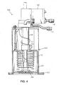
- Gifford-McMahon cryopump 300 includes vacuum vessel 320 with vacuum vessel flange 330 containing radiation shield 325, frontal cryopanel array 340 connected to radiation shield 325, and cryopanel array 350 connected to second stage cold station 190, which is connected to second stage displacer 115 of cryogenic refrigerator 105.
- second stage displacer 115 the low temperature side contains second stage regenerative heat exchanger material 170 (not shown) made of a regenerative heat exchanger material of this invention for extremely low temperature.
- the first stage regenerative heat exchanger material (not shown in FIG. 4 ) and the second stage regenerative heat exchanger material (not shown in FIG. 4 ) can include at least two layers as described above, with various volumetric heat capacities as appropriate to the temperature at the respective location in the regenerator.
- the regenerative heat exchanger material can be a ternary alloy following the general formula Sn-Sb-M, wherein M is an element selected from the group consisting of Bi, Ag, Ge, Cu, La, Mg, Mn, Nd, Ni, Pd, Pt, K, Rh, Sm, Se, S, Y, Fe, In, Al, Ce, Dy, Au, Cd, Ti, P, Pr, Yb and Zn.
- M is an element selected from the group consisting of Bi, Ag, Ge, Cu, La, Mg, Mn, Nd, Ni, Pd, Pt, K, Rh, Sm, Se, S, Y, Fe, In, Al, Ce, Dy, Au, Cd, Ti, P, Pr, Yb and Zn.
- first stage cold station 160 and second stage cold station 190 include copper for a greater degree of thermal contact between the helium gas and the respective cold stations.
- a cryopump can include a pulse tube refrigerator.
- Pulse tube refrigerators are regenerative refrigerators in which a pressure wave travels back and forth through a buffer tank, a pulse tube, and a section containing the regenerative heat exchanger material.
- the pressure wave creates an oscillating gas column, called a gas piston, that functions as a compressible displacer to move the working gas back and forth through the regenerative heat exchanger material.
- a gas piston that functions as a compressible displacer to move the working gas back and forth through the regenerative heat exchanger material.
- one end of the pulse tube is cooled, creating a cold station region, and the other end of the pulse tube is heated, creating a hot station region, where heat is dissipated away from the refrigerator.
- the pressure wave can be created by a compressor connected to the pulse tube refrigerator by high and low pressure gas lines, or by oscillators such as acoustic sources and pistons, and therefore a pulse tube refrigerator has no moving parts at the cold end.
- Some pulse tube refrigerators contain an orifice between the pulse tube and the buffer tank to act as a flow resistance to enable proper phasing of the gas motion and pressure wave.
- Pulse tube refrigerators can be single stage or can contain multiple stages. The basic operation of a pulse tube refrigerator is described in Development of the Pulse Tube Refrigerator as an Efficient and Reliable Cryocooler, R. Radebaugh, Proceedings of the Institute of Refrigeration, Vol. 96 (London, 1999/2000 ).
- pulse tube cryopump 400 includes vacuum vessel 420 with vacuum flange 430 containing radiation shield 425, frontal cryopanel array 440, and cryopanel array 450.
- Pulse tube refrigerator 405 includes high pressure gas inlet A, connected to valve assembly 455, which is in fluid communication with first stage pulse tube refrigerator assembly 410, buffer tank 500, second stage refrigerator pulse tube assembly 510, and low pressure gas outlet B.
- First stage pulse tube refrigerator assembly 410 includes first stage heat exchanger 150, which is connected to first stage cold station 460, which is in fluid communication with first stage pulse tube 470, first stage hot station 480, and first stage flow restriction orifice 490.
- Second stage pulse tube refrigerator assembly 510 includes second stage heat exchanger 170, which is connected to second stage cold station 560, which is in fluid communication with second stage pulse tube 570, second stage hot station 580, and second stage flow restriction orifice 590.
- second stage heat exchanger 170 which is connected to second stage cold station 560, which is in fluid communication with second stage pulse tube 570, second stage hot station 580, and second stage flow restriction orifice 590.
- first regenerative heat exchanger material 150 can include copper mesh or an equivalent thereof.
- first stage regenerative heat exchanger material 150 and second stage regenerative heat exchanger material 170 can include at least two layers as described above, with various volumetric heat capacities as appropriate to the temperature at the respective location in the regenerator.
- the regenerative heat exchanger material can be a ternary alloy following the general formula Sn-Sb-M, wherein M is an element selected from the group consisting of Bi, Ag, Ge, Cu, La, Mg, Mn, Nd, Ni, Pd, Pt, K, Rh, Sm, Se, S, Y, Fe, In, Al, Ce, Dy, Au, Cd, Ti, P, Pr, Yb and Zn.
- first stage cold station 460 and second stage cold station 560 include copper for a greater degree of thermal contact between the helium gas and the respective cold stations.
- a cryopump can include a Stirling cryogenic refrigerator.
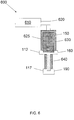
- a Stirling cryogenic refrigerator One embodiment of a two-stage Stirling cryogenic refrigerator is shown in FIG. 6 .
- Stirling cryogenic refrigerator 600 includes pressure wave source 610, pressure wave transfer line 620, a housing 625 that further includes first stage displacer 630 having a large diameter and second stage displacer 640 having a small diameter, which is connected coaxially to first stage displacer 630.
- first stage regenerative heat exchanger material 150 and second stage regenerative heat exchanger material 170 can include at least two layers as described above, with various volumetric heat capacities as appropriate to the temperature at the respective location in the regenerator.
- First stage displacer 630 accommodates first stage regenerative heat exchanger material 150.
- first stage regenerative heat exchanger material 150 can include copper or stainless steel mesh or an equivalent thereof.
- the low temperature side contains second stage regenerative heat exchanger material 170 made of a regenerative heat exchanger material of this invention for extremely low temperature that includes tin-antimony (Sn-Sb) alloy.
- First stage cold station 160 is provided at the end of first stage displacer 630 distal from pressure wave source 610, and, further, second stage cold station 190 which is colder than first stage cold station 160 is provided at the end of second stage displacer 640 distal from first stage cold station 160.
- Second stage cold station 190 has an operating temperature of about 10 K to about 25 K, and therefore it is a vacuum pumping surface for gases that condense at very low temperature or are adsorbed by other materials at these cold temperatures. Heat is extracted from first stage thermal load 112 and second stage thermal load 117.
- pressure wave source 610 can be a piston or an acoustic source.
- pressure wave source 610 is integral with housing 625, and therefore pressure wave transfer line 620 is not necessary. Referring now to FIG. 7 , all of the items shown are previously described above for FIG. 6 .
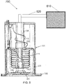
- cryopump 700 includes pressure wave source 610 connected to pressure wave transfer line 620, vacuum vessel 320 with vacuum vessel flange 330 containing radiation shield 325, frontal cryopanel array 340 connected to radiation shield 325, and cryopanel array 350 connected to second stage cold station 190, which is connected to second stage displacer 115 of cryogenic refrigerator 105.
- second stage displacer 115 the low temperature side contains second stage regenerative heat exchanger material 170 (not shown) made of a regenerative heat exchanger material of this invention for extremely low temperature that includes tin-antimony (Sn-Sb) alloy.
- pressure wave source 610 can be a piston or an acoustic source.
- pressure wave source 610 is integral with vacuum vessel 320, and therefore pressure wave transfer line 620 is not necessary. Referring now to FIG. 9 , all of the items shown are previously described above for FIG. 8 .
- a related technique provides a regenerative heat exchanger materials in the form of 0.28 mm diameter round shot with a composition of 95% Sn by weight and 5% Sb by weight were tested in a standard two stage Gifford-McMahon refrigerator.
- the Sn-Sb regenerative materials of uniform size and composition were contained in heat exchanger 170 of the second stage displacer 115 of Gifford-McMahon refrigerator 100, shown in FIG. 3 .
- the second stage was configured for direct thermal contact between the helium working gas refrigerant and copper heat station 190, shown in FIG. 3 .
- Test conditions included various settings of the temperature of the first stage, and various reciprocation rates of displacer drive motor 120, shown in FIG. 3 .
- the first stage temperature setting was controlled by changing the heat load to the first stage to maintain the required temperature.
- the heat load on the second stage was gradually increased and the temperature of the second stage was monitored.
- FIG. 10 shows a graph of the temperature of the second stage (degrees Kelvin) as a function of the heat load (Watts) applied to the second stage for a displacer operating at a motor speed of 72 rotations per minute (rpm) for regenerative heat exchanger materials composed of 95% Sn 5% Sb by weight as compared to lead (Pb) in a standard Gifford-McMahon refrigerator.
Landscapes
- Engineering & Computer Science (AREA)
- Mechanical Engineering (AREA)
- General Engineering & Computer Science (AREA)
- Physics & Mathematics (AREA)
- Thermal Sciences (AREA)
- Compressors, Vaccum Pumps And Other Relevant Systems (AREA)
- Powder Metallurgy (AREA)
- Containers, Films, And Cooling For Superconductive Devices (AREA)
Claims (8)
- Kryogenes Kühlgerät mit einem regenerativen Wärmetauschermaterial in thermischem Kontakt mit einem Arbeitsgas, wobei das kryogene Kühlgerät mindestens eine Kühlstufe mit dem regenerativen Wärmetauschermaterial umfasst, wobei das regenerative Wärmetauschermaterial eine ternäre Legierung ist, die einer allgemeinen Formel
Sn-Sb-M folgt, wobei M mindestens ein Element ist, das aus der Gruppe ausgewählt ist, die Bi, Ag, Ge, Cu, La, Mg, Mn, Nd, Ni, Pd, Pt, K, Rh, Sm, Se, S, Y, Fe, In, Al, Ce, Dy, Cd, Ti, Au, P, Pr, Yb und Zn umfasst, wobei das Sn-Sb-M-Legierungsmaterial aus etwa 0,01% bis etwa 40% nach Gewicht aus M, von etwa 0,1% bis etwa 43% nach Gewicht aus Sb, und von etwa 50% bis etwa 99,5% nach Gewicht aus Sn besteht. - Kryogenes Kühlgerät nach Anspruch 1, wobei das kryogene Kühlgerät ein kryogenes Gifford-McMahon-Kühlgerät, ein kryogenes Impulsrohr-Kühlgerät, oder ein kryogenes Stirling-Kühlgerät ist.
- Kryogenes Kühlgerät nach Anspruch 1, das weiter eine Kryopumpe aufweist, die mindestens eine durch das Kühlgerät gekühlte Kryotafel aufweist und zum Kondensieren oder Adsorbieren von Gasen ausgebildet ist.
- Kryogenes Kühlgerät nach Anspruch 1, wobei mindestens eine Kühlstufe mindestens zwei Schichten von regenerativem Wärmetauschermaterial aufweist.
- Kryogenes Kühlgerät nach Anspruch 1, wobei mindestens eine Kühlstufe weiter eine kalte Station in direktem thermischem Kontakt mit dem Arbeitsgas aufweist.
- Kryogenes Kühlgerät nach Anspruch 4, wobei die ternäre Legierung in einer Schicht vorgesehen ist und mindestens eine weitere Schicht mindestens ein Seltenerdelement aufweist.
- Kryogenes Kühlgerät nach Anspruch 4, wobei die ternäre Legierung in einer Schicht vorgesehen ist und mindestens eine weitere Schicht eine intermetallische Seltenerd-Verbindung von einem oder mehreren Seltenerdelementen mit einem Nicht-Seltenerdmetall aufweist.
- Kryogenes Kühlgerät nach Anspruch 4, wobei die ternäre Legierung in einer Schicht vorgesehen ist und mindestens eine weitere Schicht eine Festlösungslegierung von Seltenerdelementen aufweist.
Applications Claiming Priority (2)
| Application Number | Priority Date | Filing Date | Title |
|---|---|---|---|
| US12303708P | 2008-04-04 | 2008-04-04 | |
| PCT/US2009/039419 WO2009146120A1 (en) | 2008-04-04 | 2009-04-03 | Cryogenic pump employing tin-antimony alloys and methods of use |
Publications (3)
| Publication Number | Publication Date |
|---|---|
| EP2286087A1 EP2286087A1 (de) | 2011-02-23 |
| EP2286087A4 EP2286087A4 (de) | 2017-04-19 |
| EP2286087B1 true EP2286087B1 (de) | 2021-06-02 |
Family
ID=41377492
Family Applications (1)
| Application Number | Title | Priority Date | Filing Date |
|---|---|---|---|
| EP09755482.8A Active EP2286087B1 (de) | 2008-04-04 | 2009-04-03 | Kryogene pumpe mit zinnantimonlegierungen und verfahren zu ihrer verwendung |
Country Status (7)
| Country | Link |
|---|---|
| US (1) | US9567988B2 (de) |
| EP (1) | EP2286087B1 (de) |
| JP (1) | JP5492184B2 (de) |
| KR (1) | KR101679638B1 (de) |
| CN (1) | CN102046975B (de) |
| TW (2) | TWI490408B (de) |
| WO (1) | WO2009146120A1 (de) |
Families Citing this family (26)
| Publication number | Priority date | Publication date | Assignee | Title |
|---|---|---|---|---|
| TWI490408B (zh) * | 2008-04-04 | 2015-07-01 | Brooks Automation Inc | 利用錫鎵合金的低溫泵 |
| KR101343891B1 (ko) * | 2010-08-17 | 2013-12-20 | (주)바이오니아 | 써멀 사이클러용 저 비열성 복합 소재 |
| US8610434B2 (en) * | 2011-07-21 | 2013-12-17 | ColdEdge Technologies, Inc. | Cryogen-free cooling system for electron paramagnetic resonance system |
| CN102560311A (zh) * | 2012-03-16 | 2012-07-11 | 鹰潭市众鑫成铜业有限公司 | 一种镀锡线热镀过程中使用的合金 |
| JP5936938B2 (ja) * | 2012-07-11 | 2016-06-22 | 住友重機械工業株式会社 | 極低温蓄冷器の製造方法 |
| EP2907861B1 (de) * | 2012-10-09 | 2019-02-27 | Kabushiki Kaisha Toshiba | Partikelförmiges speichermedium für seltene erden, gruppe partikelförmiger speichermedien für seltene erden und kühlkopf damit, supraleitender magnet, inspektionsvorrichtung und kryopumpe |
| JP6084119B2 (ja) * | 2013-05-27 | 2017-02-22 | 住友重機械工業株式会社 | クライオポンプ |
| JP6165618B2 (ja) * | 2013-06-20 | 2017-07-19 | 住友重機械工業株式会社 | 蓄冷材および蓄冷式冷凍機 |
| TWI482864B (zh) * | 2013-08-23 | 2015-05-01 | Univ Nat Formosa | A composition having a damping characteristic, and a damper to which the composition is applied |
| JP6305193B2 (ja) * | 2013-09-17 | 2018-04-04 | 住友重機械工業株式会社 | 蓄冷式冷凍機、一段蓄冷器、及び二段蓄冷器 |
| KR101384575B1 (ko) * | 2013-12-11 | 2014-04-11 | 지브이티 주식회사 | 소음 및 진동 저감을 위한 극저온 냉동기 및 이를 갖는 크라이오펌프 |
| CN104451253A (zh) * | 2014-12-02 | 2015-03-25 | 常熟市华阳机械制造厂 | 一种使用寿命长的船用轮架 |
| JP6773589B2 (ja) * | 2017-03-15 | 2020-10-21 | 住友重機械工業株式会社 | 極低温冷凍機 |
| JP7115836B2 (ja) | 2017-11-07 | 2022-08-09 | エム・ブイ・イー・バイオロジカル・ソリューションズ・ユー・エス・リミテッド・ライアビリティ・カンパニー | 極低温冷凍機 |
| US11788783B2 (en) * | 2017-11-07 | 2023-10-17 | MVE Biological Solutions US, LLC | Cryogenic freezer |
| US10753653B2 (en) * | 2018-04-06 | 2020-08-25 | Sumitomo (Shi) Cryogenic Of America, Inc. | Heat station for cooling a circulating cryogen |
| CN108981217A (zh) * | 2018-06-04 | 2018-12-11 | 中船重工鹏力(南京)超低温技术有限公司 | 蓄冷材料及采用该蓄冷材料的蓄冷式低温制冷机 |
| WO2020049915A1 (ja) * | 2018-09-03 | 2020-03-12 | 住友重機械工業株式会社 | クライオポンプおよびクライオポンプの監視方法 |
| CN110317972A (zh) * | 2019-07-16 | 2019-10-11 | 深圳市启晟新材科技有限公司 | 一种控制氧活度在200-300度与不锈钢相容的液态金属及其工艺 |
| CN110295300A (zh) * | 2019-07-16 | 2019-10-01 | 深圳市启晟新材科技有限公司 | 一种光热领域100-200度控氧型与不锈钢相容液态金属及其工艺 |
| CN110440475A (zh) * | 2019-07-23 | 2019-11-12 | 中船重工鹏力(南京)超低温技术有限公司 | 抗氧化蓄冷材料及采用该蓄冷材料的蓄冷式低温制冷机 |
| GB2606990B (en) * | 2021-03-31 | 2023-05-24 | Leybold Dresden Gmbh | Regenerator materials, regenerators and refrigeration systems having regenerators |
| KR102709580B1 (ko) * | 2021-04-07 | 2024-09-25 | 한국과학기술원 | 장력을 이용하여 고압 액체를 생성하는 극저온 왕복동 펌프 및 이의 동작 방법 |
| CN114855004A (zh) * | 2022-03-24 | 2022-08-05 | 北京理工大学 | 一种高屈服强度Sn二元合金的制备方法 |
| EP4616128A2 (de) * | 2022-07-13 | 2025-09-17 | Bluefors Cryocooler Technologies, Inc. | 3k-kaltkopfregeneratordesign |
| CN117053438B (zh) * | 2023-07-31 | 2024-04-30 | 南方科技大学 | 一种花洒式液氦蒸发器以及制冷机 |
Family Cites Families (31)
| Publication number | Priority date | Publication date | Assignee | Title |
|---|---|---|---|---|
| NL113898C (de) | 1957-11-14 | |||
| FR2435534A1 (fr) * | 1978-07-25 | 1980-04-04 | Snecma | Nouveaux corps poreux metalliques et leur procede de preparation |
| JPS5846540B2 (ja) * | 1979-07-23 | 1983-10-17 | 住友軽金属工業株式会社 | 非酸化性減圧雰囲気ろう付けにより組立てられる熱交換器用アルミニウム合金合せ材 |
| US4356701A (en) | 1981-05-22 | 1982-11-02 | Helix Technology Corporation | Cryopump |
| US4918930A (en) * | 1988-09-13 | 1990-04-24 | Helix Technology Corporation | Electronically controlled cryopump |
| JP2845724B2 (ja) * | 1993-06-23 | 1999-01-13 | 巍洲 橋本 | 極低温冷凍機用蓄冷器 |
| JP3265821B2 (ja) * | 1994-04-27 | 2002-03-18 | アイシン精機株式会社 | 蓄冷器 |
| US6325138B1 (en) * | 1996-10-21 | 2001-12-04 | Carrier Corporation | Article exhibiting improved resistance to galvanic corrosion |
| US5985212A (en) * | 1996-12-12 | 1999-11-16 | H-Technologies Group, Incorporated | High strength lead-free solder materials |
| FR2771160B1 (fr) * | 1997-11-17 | 2000-01-28 | Air Liquide | Unite de distillation cryogenique |
| JP3980158B2 (ja) * | 1998-03-18 | 2007-09-26 | 株式会社東芝 | 蓄冷材および蓄冷式冷凍機 |
| US6334909B1 (en) | 1998-10-20 | 2002-01-01 | Kabushiki Kaisha Toshiba | Cold-accumulating material and cold-accumulating refrigerator using the same |
| US6330801B1 (en) | 1999-06-11 | 2001-12-18 | Francis J. Whelan | Method and system for increasing cryopump capacity |
| US6318090B1 (en) * | 1999-09-14 | 2001-11-20 | Iowa State University Research Foundation, Inc. | Ductile magnetic regenerator alloys for closed cycle cryocoolers |
| CN1198897C (zh) | 2000-07-18 | 2005-04-27 | 东芝株式会社 | 蓄冷材料、蓄冷材料制造方法及使用该蓄冷材料的制冷机 |
| US7201004B2 (en) | 2002-01-08 | 2007-04-10 | Shi-Apd Cryogenics, Inc. | Panels for pulse tube cryopump |
| JP2004099822A (ja) | 2002-09-12 | 2004-04-02 | Toshiba Corp | 蓄冷材およびこれを用いた蓄冷式冷凍機 |
| JP4525192B2 (ja) * | 2003-06-13 | 2010-08-18 | 千住金属工業株式会社 | 材料成分の有効性を高める方法 |
| EP1649166B1 (de) * | 2003-06-27 | 2007-02-28 | Helix Technology Corporation | Integration einer automatisierten kryopumpensicherheitsspülung |
| JP4445230B2 (ja) * | 2003-09-02 | 2010-04-07 | 住友重機械工業株式会社 | 極低温蓄冷材、蓄冷器及び冷凍機 |
| US7223080B2 (en) * | 2004-01-22 | 2007-05-29 | Duron Paul P | Double-acting, high pressure cryogenic pump |
| US7806994B2 (en) * | 2004-05-04 | 2010-10-05 | S-Bond Technologies, Llc | Electronic package formed using low-temperature active solder including indium, bismuth, and/or cadmium |
| JP4337648B2 (ja) | 2004-06-24 | 2009-09-30 | 株式会社ニコン | Euv光源、euv露光装置、及び半導体デバイスの製造方法 |
| KR100785745B1 (ko) | 2004-08-25 | 2007-12-18 | 아루박ㆍ크라이오 가부시키가이샤 | 축냉기 및 크라이오 펌프 |
| CN100458310C (zh) * | 2004-08-25 | 2009-02-04 | 爱发科低温泵株式会社 | 蓄冷器及克莱欧泵 |
| GB0519843D0 (en) | 2005-09-29 | 2005-11-09 | Univ Cambridge Tech | Magnetocaloric refrigerant |
| TW200720005A (en) * | 2005-11-28 | 2007-06-01 | Univ Nat Central | Solder composition and soldering structure |
| US7479621B2 (en) * | 2005-12-06 | 2009-01-20 | Praxair Technology, Inc. | Magnetic annealing tool heat exchange system and processes |
| TWI490408B (zh) * | 2008-04-04 | 2015-07-01 | Brooks Automation Inc | 利用錫鎵合金的低溫泵 |
| EP2236634B1 (de) * | 2009-04-01 | 2016-09-07 | Bruker BioSpin AG | Legierungen auf Zinnbasis mit feinen Verbindungseinschlüssen für Nb3Sn-Supraleitungsdrähte |
| DE102010054640A1 (de) * | 2010-12-15 | 2012-06-21 | Benteler Automobiltechnik Gmbh | Wärmetauscher |
-
2009
- 2009-04-02 TW TW098110986A patent/TWI490408B/zh active
- 2009-04-02 TW TW104111216A patent/TWI585298B/zh active
- 2009-04-03 WO PCT/US2009/039419 patent/WO2009146120A1/en not_active Ceased
- 2009-04-03 CN CN200980120523.7A patent/CN102046975B/zh active Active
- 2009-04-03 JP JP2011503198A patent/JP5492184B2/ja active Active
- 2009-04-03 KR KR1020107024831A patent/KR101679638B1/ko active Active
- 2009-04-03 US US12/936,129 patent/US9567988B2/en active Active
- 2009-04-03 EP EP09755482.8A patent/EP2286087B1/de active Active
Non-Patent Citations (1)
| Title |
|---|
| None * |
Also Published As
| Publication number | Publication date |
|---|---|
| TWI585298B (zh) | 2017-06-01 |
| TW200946780A (en) | 2009-11-16 |
| KR20110009130A (ko) | 2011-01-27 |
| CN102046975B (zh) | 2016-10-12 |
| EP2286087A4 (de) | 2017-04-19 |
| US9567988B2 (en) | 2017-02-14 |
| KR101679638B1 (ko) | 2016-11-25 |
| EP2286087A1 (de) | 2011-02-23 |
| JP5492184B2 (ja) | 2014-05-14 |
| JP2011522198A (ja) | 2011-07-28 |
| TW201529978A (zh) | 2015-08-01 |
| US20110126553A1 (en) | 2011-06-02 |
| TWI490408B (zh) | 2015-07-01 |
| WO2009146120A1 (en) | 2009-12-03 |
| CN102046975A (zh) | 2011-05-04 |
Similar Documents
| Publication | Publication Date | Title |
|---|---|---|
| US9567988B2 (en) | Cryogenic pump employing tin—gallium alloys and methods of use | |
| US6336978B1 (en) | Heat regenerative material formed of particles or filaments | |
| JP2011522198A5 (ja) | 極低温冷凍機 | |
| JP4104004B2 (ja) | 蓄冷型極低温冷凍機 | |
| US5593517A (en) | Regenerating material and refrigerator using the same | |
| US7114341B2 (en) | Cryopump with two-stage pulse tube refrigerator | |
| JP5127226B2 (ja) | 蓄冷器及びクライオポンプ | |
| US4404808A (en) | Cryogenic refrigerator with non-metallic regenerative heat exchanger | |
| JPH0611200A (ja) | 極低温冷凍機 | |
| WO2001020233A1 (en) | Ductile magnetic regenerator alloys for closed cycle cryocoolers | |
| KR20240166920A (ko) | 극저온냉동기용 축랭재, 극저온냉동기용 축랭기 및 극저온냉동기 | |
| JP3417654B2 (ja) | 極低温冷凍機 | |
| KR100785745B1 (ko) | 축냉기 및 크라이오 펌프 | |
| JP2845724B2 (ja) | 極低温冷凍機用蓄冷器 | |
| Hands | Cryopumping | |
| JP2026055185A (ja) | 蓄冷材、冷凍機、超電導コイル組込装置及び蓄冷材の製造方法 | |
| TWI314951B (en) | Regenerator and cryopump | |
| JPH0882450A (ja) | 極低温冷凍機用蓄冷器 | |
| JPH04268166A (ja) | 極低温蓄熱物質および極低温蓄熱器 | |
| CN110440475A (zh) | 抗氧化蓄冷材料及采用该蓄冷材料的蓄冷式低温制冷机 | |
| JPH03105162A (ja) | 極低温冷凍機 | |
| JPH04313648A (ja) | 極低温冷凍機 |
Legal Events
| Date | Code | Title | Description |
|---|---|---|---|
| PUAI | Public reference made under article 153(3) epc to a published international application that has entered the european phase |
Free format text: ORIGINAL CODE: 0009012 |
|
| 17P | Request for examination filed |
Effective date: 20101101 |
|
| AK | Designated contracting states |
Kind code of ref document: A1 Designated state(s): AT BE BG CH CY CZ DE DK EE ES FI FR GB GR HR HU IE IS IT LI LT LU LV MC MK MT NL NO PL PT RO SE SI SK TR |
|
| AX | Request for extension of the european patent |
Extension state: AL BA RS |
|
| DAX | Request for extension of the european patent (deleted) | ||
| RIC1 | Information provided on ipc code assigned before grant |
Ipc: F04B 37/08 20060101AFI20170307BHEP Ipc: F04B 39/06 20060101ALI20170307BHEP Ipc: F04B 53/08 20060101ALI20170307BHEP Ipc: F25B 9/14 20060101ALI20170307BHEP |
|
| RA4 | Supplementary search report drawn up and despatched (corrected) |
Effective date: 20170316 |
|
| STAA | Information on the status of an ep patent application or granted ep patent |
Free format text: STATUS: EXAMINATION IS IN PROGRESS |
|
| 17Q | First examination report despatched |
Effective date: 20180215 |
|
| RAP1 | Party data changed (applicant data changed or rights of an application transferred) |
Owner name: EDWARDS VACUUM, LLC |
|
| GRAP | Despatch of communication of intention to grant a patent |
Free format text: ORIGINAL CODE: EPIDOSNIGR1 |
|
| STAA | Information on the status of an ep patent application or granted ep patent |
Free format text: STATUS: GRANT OF PATENT IS INTENDED |
|
| INTG | Intention to grant announced |
Effective date: 20201215 |
|
| GRAS | Grant fee paid |
Free format text: ORIGINAL CODE: EPIDOSNIGR3 |
|
| GRAA | (expected) grant |
Free format text: ORIGINAL CODE: 0009210 |
|
| STAA | Information on the status of an ep patent application or granted ep patent |
Free format text: STATUS: THE PATENT HAS BEEN GRANTED |
|
| REG | Reference to a national code |
Ref country code: CH Ref legal event code: EP |
|
| AK | Designated contracting states |
Kind code of ref document: B1 Designated state(s): AT BE BG CH CY CZ DE DK EE ES FI FR GB GR HR HU IE IS IT LI LT LU LV MC MK MT NL NO PL PT RO SE SI SK TR |
|
| REG | Reference to a national code |
Ref country code: GB Ref legal event code: FG4D |
|
| REG | Reference to a national code |
Ref country code: AT Ref legal event code: REF Ref document number: 1398689 Country of ref document: AT Kind code of ref document: T Effective date: 20210615 |
|
| REG | Reference to a national code |
Ref country code: IE Ref legal event code: FG4D |
|
| REG | Reference to a national code |
Ref country code: DE Ref legal event code: R096 Ref document number: 602009063761 Country of ref document: DE |
|
| REG | Reference to a national code |
Ref country code: LT Ref legal event code: MG9D |
|
| PG25 | Lapsed in a contracting state [announced via postgrant information from national office to epo] |
Ref country code: LT Free format text: LAPSE BECAUSE OF FAILURE TO SUBMIT A TRANSLATION OF THE DESCRIPTION OR TO PAY THE FEE WITHIN THE PRESCRIBED TIME-LIMIT Effective date: 20210602 Ref country code: FI Free format text: LAPSE BECAUSE OF FAILURE TO SUBMIT A TRANSLATION OF THE DESCRIPTION OR TO PAY THE FEE WITHIN THE PRESCRIBED TIME-LIMIT Effective date: 20210602 Ref country code: HR Free format text: LAPSE BECAUSE OF FAILURE TO SUBMIT A TRANSLATION OF THE DESCRIPTION OR TO PAY THE FEE WITHIN THE PRESCRIBED TIME-LIMIT Effective date: 20210602 Ref country code: BG Free format text: LAPSE BECAUSE OF FAILURE TO SUBMIT A TRANSLATION OF THE DESCRIPTION OR TO PAY THE FEE WITHIN THE PRESCRIBED TIME-LIMIT Effective date: 20210902 |
|
| REG | Reference to a national code |
Ref country code: NL Ref legal event code: MP Effective date: 20210602 |
|
| REG | Reference to a national code |
Ref country code: AT Ref legal event code: MK05 Ref document number: 1398689 Country of ref document: AT Kind code of ref document: T Effective date: 20210602 |
|
| PG25 | Lapsed in a contracting state [announced via postgrant information from national office to epo] |
Ref country code: SE Free format text: LAPSE BECAUSE OF FAILURE TO SUBMIT A TRANSLATION OF THE DESCRIPTION OR TO PAY THE FEE WITHIN THE PRESCRIBED TIME-LIMIT Effective date: 20210602 Ref country code: GR Free format text: LAPSE BECAUSE OF FAILURE TO SUBMIT A TRANSLATION OF THE DESCRIPTION OR TO PAY THE FEE WITHIN THE PRESCRIBED TIME-LIMIT Effective date: 20210903 Ref country code: LV Free format text: LAPSE BECAUSE OF FAILURE TO SUBMIT A TRANSLATION OF THE DESCRIPTION OR TO PAY THE FEE WITHIN THE PRESCRIBED TIME-LIMIT Effective date: 20210602 Ref country code: NO Free format text: LAPSE BECAUSE OF FAILURE TO SUBMIT A TRANSLATION OF THE DESCRIPTION OR TO PAY THE FEE WITHIN THE PRESCRIBED TIME-LIMIT Effective date: 20210902 Ref country code: PL Free format text: LAPSE BECAUSE OF FAILURE TO SUBMIT A TRANSLATION OF THE DESCRIPTION OR TO PAY THE FEE WITHIN THE PRESCRIBED TIME-LIMIT Effective date: 20210602 |
|
| PG25 | Lapsed in a contracting state [announced via postgrant information from national office to epo] |
Ref country code: RO Free format text: LAPSE BECAUSE OF FAILURE TO SUBMIT A TRANSLATION OF THE DESCRIPTION OR TO PAY THE FEE WITHIN THE PRESCRIBED TIME-LIMIT Effective date: 20210602 Ref country code: PT Free format text: LAPSE BECAUSE OF FAILURE TO SUBMIT A TRANSLATION OF THE DESCRIPTION OR TO PAY THE FEE WITHIN THE PRESCRIBED TIME-LIMIT Effective date: 20211004 Ref country code: NL Free format text: LAPSE BECAUSE OF FAILURE TO SUBMIT A TRANSLATION OF THE DESCRIPTION OR TO PAY THE FEE WITHIN THE PRESCRIBED TIME-LIMIT Effective date: 20210602 Ref country code: ES Free format text: LAPSE BECAUSE OF FAILURE TO SUBMIT A TRANSLATION OF THE DESCRIPTION OR TO PAY THE FEE WITHIN THE PRESCRIBED TIME-LIMIT Effective date: 20210602 Ref country code: AT Free format text: LAPSE BECAUSE OF FAILURE TO SUBMIT A TRANSLATION OF THE DESCRIPTION OR TO PAY THE FEE WITHIN THE PRESCRIBED TIME-LIMIT Effective date: 20210602 Ref country code: SK Free format text: LAPSE BECAUSE OF FAILURE TO SUBMIT A TRANSLATION OF THE DESCRIPTION OR TO PAY THE FEE WITHIN THE PRESCRIBED TIME-LIMIT Effective date: 20210602 Ref country code: EE Free format text: LAPSE BECAUSE OF FAILURE TO SUBMIT A TRANSLATION OF THE DESCRIPTION OR TO PAY THE FEE WITHIN THE PRESCRIBED TIME-LIMIT Effective date: 20210602 Ref country code: CZ Free format text: LAPSE BECAUSE OF FAILURE TO SUBMIT A TRANSLATION OF THE DESCRIPTION OR TO PAY THE FEE WITHIN THE PRESCRIBED TIME-LIMIT Effective date: 20210602 |
|
| REG | Reference to a national code |
Ref country code: DE Ref legal event code: R097 Ref document number: 602009063761 Country of ref document: DE |
|
| PLBE | No opposition filed within time limit |
Free format text: ORIGINAL CODE: 0009261 |
|
| STAA | Information on the status of an ep patent application or granted ep patent |
Free format text: STATUS: NO OPPOSITION FILED WITHIN TIME LIMIT |
|
| PG25 | Lapsed in a contracting state [announced via postgrant information from national office to epo] |
Ref country code: DK Free format text: LAPSE BECAUSE OF FAILURE TO SUBMIT A TRANSLATION OF THE DESCRIPTION OR TO PAY THE FEE WITHIN THE PRESCRIBED TIME-LIMIT Effective date: 20210602 |
|
| 26N | No opposition filed |
Effective date: 20220303 |
|
| PG25 | Lapsed in a contracting state [announced via postgrant information from national office to epo] |
Ref country code: IT Free format text: LAPSE BECAUSE OF FAILURE TO SUBMIT A TRANSLATION OF THE DESCRIPTION OR TO PAY THE FEE WITHIN THE PRESCRIBED TIME-LIMIT Effective date: 20210602 |
|
| REG | Reference to a national code |
Ref country code: CH Ref legal event code: PL |
|
| REG | Reference to a national code |
Ref country code: DE Ref legal event code: R082 Ref document number: 602009063761 Country of ref document: DE Representative=s name: FLEUCHAUS & GALLO PARTNERSCHAFT MBB - PATENT- , DE Ref country code: DE Ref legal event code: R082 Ref document number: 602009063761 Country of ref document: DE Representative=s name: FLEUCHAUS & GALLO PARTNERSCHAFT MBB PATENTANWA, DE |
|
| REG | Reference to a national code |
Ref country code: BE Ref legal event code: MM Effective date: 20220430 |
|
| PG25 | Lapsed in a contracting state [announced via postgrant information from national office to epo] |
Ref country code: MC Free format text: LAPSE BECAUSE OF FAILURE TO SUBMIT A TRANSLATION OF THE DESCRIPTION OR TO PAY THE FEE WITHIN THE PRESCRIBED TIME-LIMIT Effective date: 20210602 Ref country code: LU Free format text: LAPSE BECAUSE OF NON-PAYMENT OF DUE FEES Effective date: 20220403 Ref country code: LI Free format text: LAPSE BECAUSE OF NON-PAYMENT OF DUE FEES Effective date: 20220430 Ref country code: CH Free format text: LAPSE BECAUSE OF NON-PAYMENT OF DUE FEES Effective date: 20220430 |
|
| PG25 | Lapsed in a contracting state [announced via postgrant information from national office to epo] |
Ref country code: BE Free format text: LAPSE BECAUSE OF NON-PAYMENT OF DUE FEES Effective date: 20220430 |
|
| PG25 | Lapsed in a contracting state [announced via postgrant information from national office to epo] |
Ref country code: IE Free format text: LAPSE BECAUSE OF NON-PAYMENT OF DUE FEES Effective date: 20220403 |
|
| P01 | Opt-out of the competence of the unified patent court (upc) registered |
Effective date: 20230420 |
|
| PG25 | Lapsed in a contracting state [announced via postgrant information from national office to epo] |
Ref country code: HU Free format text: LAPSE BECAUSE OF FAILURE TO SUBMIT A TRANSLATION OF THE DESCRIPTION OR TO PAY THE FEE WITHIN THE PRESCRIBED TIME-LIMIT; INVALID AB INITIO Effective date: 20090403 |
|
| PG25 | Lapsed in a contracting state [announced via postgrant information from national office to epo] |
Ref country code: MK Free format text: LAPSE BECAUSE OF FAILURE TO SUBMIT A TRANSLATION OF THE DESCRIPTION OR TO PAY THE FEE WITHIN THE PRESCRIBED TIME-LIMIT Effective date: 20210602 Ref country code: CY Free format text: LAPSE BECAUSE OF FAILURE TO SUBMIT A TRANSLATION OF THE DESCRIPTION OR TO PAY THE FEE WITHIN THE PRESCRIBED TIME-LIMIT Effective date: 20210602 |
|
| PG25 | Lapsed in a contracting state [announced via postgrant information from national office to epo] |
Ref country code: TR Free format text: LAPSE BECAUSE OF FAILURE TO SUBMIT A TRANSLATION OF THE DESCRIPTION OR TO PAY THE FEE WITHIN THE PRESCRIBED TIME-LIMIT Effective date: 20210602 |
|
| PG25 | Lapsed in a contracting state [announced via postgrant information from national office to epo] |
Ref country code: MT Free format text: LAPSE BECAUSE OF FAILURE TO SUBMIT A TRANSLATION OF THE DESCRIPTION OR TO PAY THE FEE WITHIN THE PRESCRIBED TIME-LIMIT Effective date: 20210602 |
|
| PGFP | Annual fee paid to national office [announced via postgrant information from national office to epo] |
Ref country code: DE Payment date: 20250429 Year of fee payment: 17 |
|
| PGFP | Annual fee paid to national office [announced via postgrant information from national office to epo] |
Ref country code: GB Payment date: 20250428 Year of fee payment: 17 |
|
| PGFP | Annual fee paid to national office [announced via postgrant information from national office to epo] |
Ref country code: FR Payment date: 20250425 Year of fee payment: 17 |