EP2287052A2 - Procédé d'assemblage de pince métallique et ressorts de corps de balai d'essuie-glace de véhicule - Google Patents
Procédé d'assemblage de pince métallique et ressorts de corps de balai d'essuie-glace de véhicule Download PDFInfo
- Publication number
- EP2287052A2 EP2287052A2 EP09175404A EP09175404A EP2287052A2 EP 2287052 A2 EP2287052 A2 EP 2287052A2 EP 09175404 A EP09175404 A EP 09175404A EP 09175404 A EP09175404 A EP 09175404A EP 2287052 A2 EP2287052 A2 EP 2287052A2
- Authority
- EP
- European Patent Office
- Prior art keywords
- clamp
- body springs
- wiper blade
- holes
- protrusions
- Prior art date
- Legal status (The legal status is an assumption and is not a legal conclusion. Google has not performed a legal analysis and makes no representation as to the accuracy of the status listed.)
- Granted
Links
Images



Classifications
-
- B—PERFORMING OPERATIONS; TRANSPORTING
- B60—VEHICLES IN GENERAL
- B60S—SERVICING, CLEANING, REPAIRING, SUPPORTING, LIFTING, OR MANOEUVRING OF VEHICLES, NOT OTHERWISE PROVIDED FOR
- B60S1/00—Cleaning of vehicles
- B60S1/02—Cleaning windscreens, windows or optical devices
- B60S1/04—Wipers or the like, e.g. scrapers
- B60S1/32—Wipers or the like, e.g. scrapers characterised by constructional features of wiper blade arms or blades
- B60S1/38—Wiper blades
- B60S1/3848—Flat-type wiper blade, i.e. without harness
- B60S1/3849—Connectors therefor; Connection to wiper arm; Attached to blade
- B60S1/3851—Mounting of connector to blade assembly
- B60S1/3858—Mounting of connector to blade assembly with protrusions cooperating with holes
-
- B—PERFORMING OPERATIONS; TRANSPORTING
- B60—VEHICLES IN GENERAL
- B60S—SERVICING, CLEANING, REPAIRING, SUPPORTING, LIFTING, OR MANOEUVRING OF VEHICLES, NOT OTHERWISE PROVIDED FOR
- B60S1/00—Cleaning of vehicles
- B60S1/02—Cleaning windscreens, windows or optical devices
- B60S1/04—Wipers or the like, e.g. scrapers
- B60S1/32—Wipers or the like, e.g. scrapers characterised by constructional features of wiper blade arms or blades
- B60S1/40—Connections between blades and arms
-
- B—PERFORMING OPERATIONS; TRANSPORTING
- B60—VEHICLES IN GENERAL
- B60S—SERVICING, CLEANING, REPAIRING, SUPPORTING, LIFTING, OR MANOEUVRING OF VEHICLES, NOT OTHERWISE PROVIDED FOR
- B60S1/00—Cleaning of vehicles
- B60S1/02—Cleaning windscreens, windows or optical devices
- B60S1/04—Wipers or the like, e.g. scrapers
- B60S1/32—Wipers or the like, e.g. scrapers characterised by constructional features of wiper blade arms or blades
-
- B—PERFORMING OPERATIONS; TRANSPORTING
- B60—VEHICLES IN GENERAL
- B60S—SERVICING, CLEANING, REPAIRING, SUPPORTING, LIFTING, OR MANOEUVRING OF VEHICLES, NOT OTHERWISE PROVIDED FOR
- B60S1/00—Cleaning of vehicles
- B60S1/02—Cleaning windscreens, windows or optical devices
- B60S1/04—Wipers or the like, e.g. scrapers
- B60S1/32—Wipers or the like, e.g. scrapers characterised by constructional features of wiper blade arms or blades
- B60S1/38—Wiper blades
- B60S1/3848—Flat-type wiper blade, i.e. without harness
- B60S1/3849—Connectors therefor; Connection to wiper arm; Attached to blade
- B60S1/3851—Mounting of connector to blade assembly
- B60S1/3855—Mounting of connector to blade assembly by welding, gluing or the like
-
- B—PERFORMING OPERATIONS; TRANSPORTING
- B60—VEHICLES IN GENERAL
- B60S—SERVICING, CLEANING, REPAIRING, SUPPORTING, LIFTING, OR MANOEUVRING OF VEHICLES, NOT OTHERWISE PROVIDED FOR
- B60S1/00—Cleaning of vehicles
- B60S1/02—Cleaning windscreens, windows or optical devices
- B60S1/04—Wipers or the like, e.g. scrapers
- B60S1/32—Wipers or the like, e.g. scrapers characterised by constructional features of wiper blade arms or blades
- B60S1/38—Wiper blades
- B60S1/3848—Flat-type wiper blade, i.e. without harness
- B60S1/3874—Flat-type wiper blade, i.e. without harness with a reinforcing vertebra
- B60S1/3875—Flat-type wiper blade, i.e. without harness with a reinforcing vertebra rectangular section
- B60S1/3879—Flat-type wiper blade, i.e. without harness with a reinforcing vertebra rectangular section placed in side grooves in the squeegee
-
- Y—GENERAL TAGGING OF NEW TECHNOLOGICAL DEVELOPMENTS; GENERAL TAGGING OF CROSS-SECTIONAL TECHNOLOGIES SPANNING OVER SEVERAL SECTIONS OF THE IPC; TECHNICAL SUBJECTS COVERED BY FORMER USPC CROSS-REFERENCE ART COLLECTIONS [XRACs] AND DIGESTS
- Y10—TECHNICAL SUBJECTS COVERED BY FORMER USPC
- Y10T—TECHNICAL SUBJECTS COVERED BY FORMER US CLASSIFICATION
- Y10T29/00—Metal working
- Y10T29/49—Method of mechanical manufacture
- Y10T29/49826—Assembling or joining
Definitions
- the present invention relates to a method of assembling a metal clamp and body springs of a wiper blade for vehicles.
- a wiper mounted to a wind shield glass of a vehicle serves to prevent forward visibility of a driver from being disturbed due to rain or snow present on the wind shield glass during driving of the vehicle in rain or in snow and, in addition, to wipe the wind shield glass clean.
- a wiper system is mounted at a predetermined part of a chassis of the vehicle below the wind shield glass of the vehicle, and a wiper blade performs reciprocation, i.e., alternating motions, on the wind shield glass from side to side in a fan shape when the wiper blade is driven by a motor.
- Such a wiper blade for wiping foreign matter off a wind shield glass of a vehicle is disclosed in Korean Patent Application No. 2005-12755 , which has been filed in the name of the applicant of the present application.
- the conventional wiper blade includes body springs integrally formed and having a long groove formed at middle regions of the body springs, such that a fixing coupling member is fitted in the long groove, in the longitudinal direction thereof for supporting the wiper blade, the fixing coupling member fitted in the long groove of the body springs such that a rubber is fixedly coupled to the body springs, the fixing coupling member having clip fitting grooves formed at the upper part thereof and protrusions formed at the lower part thereof such that the protrusions are fitted in fitting grooves formed at the rubber, clips fitted in the clip fitting grooves formed at the upper part of the fixing coupling member for fixing the upper sides of the body springs in a tight contact manner, the rubber having the fitting grooves, in which the protrusions of the fixing coupling member are fitted, formed at the upper part thereof, the lower part of the rubber being in tight contact with a wind shield glass of a vehicle for wiping the wind shield glass clean, and a spoiler having depressions formed at opposite sides thereof in the longitudinal direction of the body springs.
- the rubber is fixedly coupled to the body springs by the fixing coupling member, and the fixing coupling member is in tight contact with the upper sides of the body springs by the clips.
- the number of parts to be assembled is large, and therefore, the structure of the wiper blade is very complicated while manufacturing costs of the wiper blade are greatly increased.
- a process of assembling the wiper blade is also complicated in proportion to the number of parts to be assembled, with the result that assembly productivity is also deteriorated.
- a wiper blade including a clamp, made of a plastic material, to which an adapter mounted to an arm connected to a chassis of a vehicle is detachably mounted and body springs for elastically supporting a rubber configured to wipe a wind shield glass clean, the assembly between the clamp and the body springs being achieved by mounting pins.
- a wiper blade serves to not only wipe rain off a wind shield glass but also remove snow from the wind shield glass.
- the clamp has toughness and ductility lower than those of a clamp which is made of a metal material although the plastic clamp may be easily manufactured by injection molding.
- the conventional wiper blade does not satisfy a snow block test during development of products, and, in addition, the shape of the clamp may be deformed.
- the clamp when the clamp is coupled to the body springs using the mounting pins positioned between the clamp and the body springs, assembly tolerance occurs between the clamp and the body springs. As a result, the coupling between the clamp and the body springs may loosen during use of the wiper blade for a long period of time, and therefore, the wiper blade may malfunction and thus stable use of the wiper blade may not be achieved.
- a pair of support members 133 are configured to support body springs 120 at opposite ends of the body springs 120 in the longitudinal direction of the body springs 120.
- the overall size of the clamp 130 is large, and therefore, material costs are increased.
- each of the body springs 120 it is necessary for each of the body springs 120 to have a predetermined radius of curvature as indicated by a dashed dotted line in FIG. 12 .
- the distance between the support members 133 of the conventional clamp 130, which support the body springs 120 is large.
- the present invention has been made in view of the above problems, and it is an object of the present invention to provide a method of assembling a metal clamp and body springs of a wiper blade for vehicles that is capable of achieving secure coupling between the clamp and the body springs and reducing deformation in shape of the clamp, thereby achieving stable use of a wiper blade in snow as well as in rain and, in addition, improving rigidity of the wiper blade.
- the above and other objects can be accomplished by the provision of a method of assembling a metal clamp and body springs of a wiper blade for vehicles, the wiper blade including a rubber disposed in tight contact with a wind shield glass of a vehicle to which the wiper blade is mounted for wiping foreign matter off the wind shield glass, the body springs elastically supporting the rubber, the body springs being made of a metal material, an adapter mounted to an arm connected to a chassis of the vehicle, and the clamp to which the adapter is detachably mounted, the clamp being made of a metal material, the method including forming a plurality of through holes at major sides of the body springs, forming a plurality of protrusions corresponding to the through holes at a major side of the clamp such that the protrusions extend outward from the major side of the clamp, inserting the protrusions of the clamp into the respective through holes of the body springs, fixing the protrusions, which are located in the respective through holes, in the respective through holes by
- the protrusions of the clamp may be formed in a protruding manner by pressing.
- the method may further include bending the body springs such that each of the body springs has a predetermined radius of curvature after the step of forming the through holes at the body springs.
- FIG. 1 is a perspective view illustrating a wiper blade according to an embodiment of the present invention
- FIG. 2 is an exploded perspective view of the wiper blade according to the embodiment of the present invention shown in FIG. 1 ;
- FIG. 3 is a sectional view taken along line III-III of FIG. 2 ;
- FIG. 4 is an enlarged perspective view, in part, illustrating through holes formed in body springs of the wiper blade according to the embodiment of the present invention shown in FIG. 1 ;
- FIG. 5 is a sectional view illustrating a process for forming protrusions at a clamp of the wiper blade according to the embodiment of the present invention shown in FIG. 1 ;
- FIG. 6 is a perspective view of the clamp manufactured by the process shown in FIG. 5 ;
- FIG. 7 is an exploded perspective view illustrating the clamp and the body springs before assembly
- FIG. 8 is a sectional view illustrating a state in which the protrusions of the clamp shown in FIG. 7 are fitted in the respective through holes of the body springs shown in FIG. 7 ;
- FIG. 9 is a sectional view illustrating a process for fixing the protrusions of the clamp in the through holes of the body springs of the wiper blade according to the embodiment of the present invention shown in FIG. 1 by pressure welding;
- FIG. 10 is a perspective view of the clamp and the body springs manufactured by the process shown in FIG. 9 ;
- FIG. 11 is a perspective view illustrating a state in which a conventional clamp is coupled to conventional body springs.
- FIG. 12 is a side view of the clamp and the body springs shown in FIG. 11 .
- FIGS. 1 to 3 illustrate a wiper blade 1 for vehicles according to an embodiment of the present invention.
- the wiper blade 1 for vehicles includes a rubber 10, body springs 20, and a clamp 30.
- the rubber 10 has a predetermined length.
- the rubber 10 is elastically supported by the body springs 20, such that the rubber 10 is in tight contact with a wind shield glass of a vehicle to which the wiper blade for vehicles according to the embodiment of the present invention is applied, for wiping foreign matter off the wind shield glass.
- the rubber 10 is provided at opposite sides of the top thereof with coupling grooves 11, which extend in the longitudinal direction of the rubber 10. The bottom of the rubber 10 is in tight contact with the wind shield glass of the vehicle for securing high forward visibility.
- the body springs 20 are provided in a pair.
- Each of the body springs 20 is configured in the form of a belt having a predetermined length.
- Each of the body springs 20 is made of a metal material.
- the body springs 20 serve to support the wiper blade 1.
- the clamp 30 is coupled to the body springs 20.
- the rubber 10 is coupled to the body springs 20 such that flexibility and elasticity of the rubber 10 are maintained by the body springs 20. Consequently, the body springs 20 serve to enable the rubber 10 to be in tight contact with various types of wind shield glasses.
- Each of the body springs 20 may be bent so as to have a predetermined radius of curvature corresponding to the wind shield glass of the vehicle.
- the clamp 30 is detachably coupled an adapter 5 to which an arm connected to a chassis of the vehicle is mounted.
- the clamp 30 is coupled to the body springs 20.
- the clamp 30 is made of a metal material exhibiting higher toughness and ductility than a conventional plastic material such that the clamp 30 satisfies a snow block test and exhibits reduced deformation in shape.
- a rubber passageway 31 is formed in a depressed manner at a major side of the clamp 30 facing the body springs 20 such that the upper part of the rubber 10 passes through the rubber passageway 31.
- each of the protrusions 33 is configured in the form of a cylinder opened at one end thereof by pressing.
- the protrusions 33 are integrally formed at the major side of the clamp 30 such that the protrusions 33 extend outward from the major side of the clamp 30.
- each of the protrusions 33 has a height greater than the thickness of each of the body springs 20 and, at the same time, a diameter equal to or less than that of each of the through holes 21 of the body springs 20.
- the protrusions 33 integrally formed at the major side of the clamp 30 such that the protrusions 33 extend outward from the major side of the clamp 30 are fixed in the respective through holes 21 of the body springs 20 by pressure welding or riveting using a press or the like.
- the clamp 30 is securely coupled to the body springs 20 without the occurrence of assembly tolerance, and therefore, the coupling between the clamp 30 and the body springs 20 is prevented from loosening even when the wiper blade 1 is used for a long period of time, thereby achieving optimum wiping performance of the wiper blade 1.
- Unexplained reference numeral 40 indicates a pair of spoilers.
- the spoilers 40 surround opposite-side parts of the body springs 20 in a state in which the clamp 30 is disposed between the spoilers 40.
- the spoilers 40 serve to prevent the wiper blade 1 from rising during high-speed travelling, thereby improving wiping efficiency of the wiper blade 1.
- Unexplained reference numeral 50 indicates a pair of end caps.
- the end caps 50 are mounted to opposite ends of the body springs 20 for providing an aesthetically pleasing appearance to the wiper blade 1 at the opposite ends thereof and, in addition, preventing the opposite ends of the body springs 20 from being damaged due to external impact or environmental wear.
- a plurality of through holes 21 are formed at major sides of body springs 20 using a press (not shown).
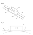
- a clamp 30 is located on a bed 61a of the press in which a plurality of grooves 63 are formed, and a ram 65a of the press having a plurality of jigs 67a each having an outer diameter less than that of each of the grooves 63 of the bed 61a is lowered toward the bed 61a to form a plurality of protrusions 33 corresponding to the respective through holes 21 of the body springs 20 at a major side of the clamp 30 such that the protrusions 33 extend outward from the major side of the clamp 30, as shown in FIG. 6 .
- each of the protrusions 33 has a height greater than the thickness of each of the body springs 20 and, at the same time, a diameter equal to or less than that of each of the through holes 21 of the body springs 20, by pressing. Also, the protrusions 33 are formed at the major side of the clamp 30 such that the protrusions 33 extend outward from the major side of the clamp 30. Each of the protrusions 33 is configured in the form of a cylinder opened at one end thereof.
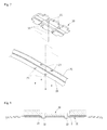
- FIG. 7 is an exploded perspective view illustrating the clamp 30 and the body springs 20 before assembly, i.e., before the protrusions 33 of the clamp 30 are inserted into the respective through holes 21 of the body springs 20.
- the body springs 20, to which the clamp 30 is temporarily assembled are disposed between the bed 61b of the press having the jigs 67b, each of which is configured in a shape corresponding to the inner diameter of each of the protrusions 33 and the ram 65b of the press, and the ram 65b of the press is lowered toward the bed 61b of the press such that the protrusions 33 of the clamp 30, which are located in the through holes 21 of the body springs 20, are fixed in the through holes 21 of the body springs 20 by pressure welding.
- the clamp 30 is mounted to the body springs 20.
- the assembly of the metal clamp 30 and the body springs 20 of the wiper blade 1 for vehicles is completed as shown in FIG. 10 .
- the clamp 30 is securely coupled to the body springs 20 without the occurrence of assembly tolerance, and therefore, the coupling between the clamp 30 and the body springs 20 is prevented from loosening even when the wiper blade 1 is used for a long period of time, thereby achieving stable use of the wiper blade 1.
- the clamp 30 is made of a metal material exhibiting higher toughness and ductility than a conventional plastic material. Consequently, the coupling between the clamp 30 and the body springs 20 is achieved without trouble even during pressure welding using the press, thereby exhibiting excellent coupling efficiency, satisfying a snow block test, and exhibiting reduced deformation in shape.
- the body springs 20 may be bent such that each of the body springs 20 has a predetermined radius of curvature corresponding to a wind shield glass of a vehicle to which the present invention is applied.
- end caps 50 are mounted to opposite ends of the body springs 20. In this way, the assembly of the wiper blade 1 is completed.
- a plurality of protrusions are formed at a major side of a clamp, which is made of a metal material, in a protruding manner such that the protrusions correspond to through holes formed in body springs, the protrusions of the clamp are fixed in the corresponding through holes of the body springs by pressure welding or riveting such that the clamp is mounted to the body springs, thereby achieving secure coupling between the clamp and the body springs, reducing deformation in shape of the clamp, and achieving stable use of a wiper blade in snow as well as in rain. Consequently, the present invention with the above-stated construction has industrial applicability.
Landscapes
- Engineering & Computer Science (AREA)
- Mechanical Engineering (AREA)
- Insertion Pins And Rivets (AREA)
- Clamps And Clips (AREA)
- Springs (AREA)
Applications Claiming Priority (1)
| Application Number | Priority Date | Filing Date | Title |
|---|---|---|---|
| KR1020090077656A KR101105340B1 (ko) | 2009-08-21 | 2009-08-21 | 차량용 와이퍼 블레이드의 금속재 클램프와 바디 스프링의 조립방법 |
Publications (3)
| Publication Number | Publication Date |
|---|---|
| EP2287052A2 true EP2287052A2 (fr) | 2011-02-23 |
| EP2287052A3 EP2287052A3 (fr) | 2017-10-11 |
| EP2287052B1 EP2287052B1 (fr) | 2019-01-23 |
Family
ID=43067120
Family Applications (1)
| Application Number | Title | Priority Date | Filing Date |
|---|---|---|---|
| EP09175404.4A Not-in-force EP2287052B1 (fr) | 2009-08-21 | 2009-11-09 | Procédé d'assemblage de pince métallique et ressorts de corps de balai d'essuie-glace de véhicule |
Country Status (5)
| Country | Link |
|---|---|
| US (1) | US8839482B2 (fr) |
| EP (1) | EP2287052B1 (fr) |
| KR (1) | KR101105340B1 (fr) |
| CN (1) | CN101992747A (fr) |
| CA (1) | CA2685641C (fr) |
Cited By (5)
| Publication number | Priority date | Publication date | Assignee | Title |
|---|---|---|---|---|
| WO2012113712A1 (fr) * | 2011-02-24 | 2012-08-30 | Robert Bosch Gmbh | Procédé de fabrication de balais d'essuie-glace et balai d'essuie-glace pour nettoyer des vitres |
| WO2012171700A1 (fr) * | 2011-06-15 | 2012-12-20 | Robert Bosch Gmbh | Balai d'essuie-glace destiné à nettoyer des vitres, en particulier de véhicules automobiles |
| DE102012101338A1 (de) * | 2011-09-16 | 2013-03-21 | Dung Jyuu Enterprise Co., Ltd. | Wischerblatt-Montagewinkel, Verfahren zur Fertigung desselben und Wischerblatt-Montagewinkel-Baugruppe |
| CN113281071A (zh) * | 2021-06-21 | 2021-08-20 | 中车青岛四方机车车辆股份有限公司 | 轨道车辆的车体安装调试结构 |
| CN115609260A (zh) * | 2022-11-08 | 2023-01-17 | 四川富士电机有限公司 | 一种雨刮臂组装装置 |
Families Citing this family (33)
| Publication number | Priority date | Publication date | Assignee | Title |
|---|---|---|---|---|
| DE102008000708A1 (de) * | 2008-03-17 | 2009-09-24 | Robert Bosch Gmbh | Wischblatt |
| EP2593340B1 (fr) * | 2010-07-12 | 2014-01-22 | Federal-Mogul S.a. | Dispositif d'essuie-glace |
| US9174609B2 (en) | 2011-04-21 | 2015-11-03 | Pylon Manufacturing Corp. | Wiper blade with cover |
| US9457768B2 (en) | 2011-04-21 | 2016-10-04 | Pylon Manufacturing Corp. | Vortex damping wiper blade |
| CN202186356U (zh) * | 2011-06-07 | 2012-04-11 | 宁波市镇海阳光交通器材有限公司 | 一种节能无骨雨刷 |
| DE102011078200A1 (de) * | 2011-06-28 | 2013-01-03 | Robert Bosch Gmbh | Wischvorrichtung |
| CA2843527C (fr) | 2011-07-28 | 2018-11-27 | Pylon Manufacturing Corp. | Adaptateur, raccord et ensemble d'essuie-glace |
| US9108595B2 (en) | 2011-07-29 | 2015-08-18 | Pylon Manufacturing Corporation | Windshield wiper connector |
| KR102005798B1 (ko) | 2011-12-14 | 2019-07-31 | 페더럴-모걸 엘엘씨 | 윈드스크린 와이퍼 장치 |
| KR101350277B1 (ko) * | 2012-01-27 | 2014-01-14 | 케이씨더블류 주식회사 | 플랫 와이퍼 블레이드 및 플랫 와이퍼 블레이드 조립체 |
| MX385411B (es) | 2012-02-24 | 2025-03-18 | Pylon Mfg Corp | Escobilla limpiaparabrisas. |
| US10723322B2 (en) | 2012-02-24 | 2020-07-28 | Pylon Manufacturing Corp. | Wiper blade with cover |
| US20130219649A1 (en) | 2012-02-24 | 2013-08-29 | Pylon Manufacturing Corp. | Wiper blade |
| KR101369629B1 (ko) * | 2012-04-06 | 2014-03-04 | 주식회사 캐프 | 차량용 와이퍼 장치 |
| USD685713S1 (en) * | 2012-06-27 | 2013-07-09 | Xiamen Fuke Car Accessories Co., Ltd. | Windshield wiper |
| US10829092B2 (en) | 2012-09-24 | 2020-11-10 | Pylon Manufacturing Corp. | Wiper blade with modular mounting base |
| US9925957B2 (en) * | 2012-12-11 | 2018-03-27 | Qinghuai Shen | Windscreen wiper strip support and windscreen wiper blade having same |
| US10166951B2 (en) | 2013-03-15 | 2019-01-01 | Pylon Manufacturing Corp. | Windshield wiper connector |
| US9387829B2 (en) * | 2013-12-13 | 2016-07-12 | Xiamen Fuke Car Accessories Co., Ltd. | Windshield wiper connector |
| US9505380B2 (en) | 2014-03-07 | 2016-11-29 | Pylon Manufacturing Corp. | Windshield wiper connector and assembly |
| WO2017063687A1 (fr) * | 2015-10-14 | 2017-04-20 | Federal-Mogul S.A. | Dispositif d'essuie-glace |
| US10363905B2 (en) | 2015-10-26 | 2019-07-30 | Pylon Manufacturing Corp. | Wiper blade |
| AU2017268008A1 (en) | 2016-05-19 | 2018-11-22 | Pylon Manufacturing Corp. | Windshield wiper connector |
| US11040705B2 (en) | 2016-05-19 | 2021-06-22 | Pylon Manufacturing Corp. | Windshield wiper connector |
| CN109311450A (zh) | 2016-05-19 | 2019-02-05 | 电缆塔制造有限公司 | 挡风玻璃雨刮器连接器 |
| CN109311452A (zh) | 2016-05-19 | 2019-02-05 | 电缆塔制造有限公司 | 挡风玻璃雨刮器连接器 |
| EP3458315B1 (fr) | 2016-05-19 | 2021-09-08 | Pylon Manufacturing Corp. | Balai d'essuie-glace |
| CN108685526A (zh) * | 2017-04-12 | 2018-10-23 | 上海拓础智能科技有限公司 | 自动导航扫地机器人 |
| CN107378486B (zh) * | 2017-09-07 | 2023-07-14 | 浙江兄弟之星汽配有限公司 | 一种有骨雨刮器自动装配系统 |
| CN109571015A (zh) * | 2019-01-24 | 2019-04-05 | 长沙纽泰自动化科技有限公司 | 一种雨刷连杆装配线及装配方法 |
| CN116788207A (zh) * | 2022-03-14 | 2023-09-22 | 丹阳镇威汽配有限公司 | 雨刷配件座的组合结构 |
| CN114932518B (zh) * | 2022-05-24 | 2024-04-19 | 江苏云睿汽车电器系统有限公司 | 一种用于组装无骨超声波焊接雨刷刷片的治具 |
| CN117001320B (zh) * | 2023-08-23 | 2025-08-22 | 浙江科朗汽车配件有限公司 | 一种新能源汽车无骨雨刷器自动安装系统 |
Citations (1)
| Publication number | Priority date | Publication date | Assignee | Title |
|---|---|---|---|---|
| KR20050012755A (ko) | 2002-05-28 | 2005-02-02 | 코닌클리케 필립스 일렉트로닉스 엔.브이. | 더 높은 질의 참조 프레임들을 이용하는 향상된 효율의미세 입상 계위 시간 프레임워크 |
Family Cites Families (13)
| Publication number | Priority date | Publication date | Assignee | Title |
|---|---|---|---|---|
| JPH10286726A (ja) | 1997-04-14 | 1998-10-27 | Toyota Motor Corp | 圧入部材の構造および圧入制御方法 |
| DE19735300C2 (de) * | 1997-08-14 | 1999-06-02 | Bosch Gmbh Robert | Wischblatt zum Reinigen von Scheiben an Kraftfahrzeugen |
| US7546660B2 (en) * | 2002-06-28 | 2009-06-16 | Robert Bosch Gmbh | Wiper blade with connecting part |
| US20060026786A1 (en) * | 2004-08-04 | 2006-02-09 | Shu-Lan Ku | Windshield wiper |
| KR100640276B1 (ko) * | 2004-08-16 | 2006-10-31 | 이재식 | 프레스 가공방법 및 그 가공방법에 의해 생산된 물건 |
| WO2006088274A1 (fr) * | 2005-02-16 | 2006-08-24 | Cap Inc | Balai d'essuie-glace pour automobile |
| US7587783B1 (en) * | 2005-07-26 | 2009-09-15 | Chin-Lien Lin | Windshield wiper |
| US8037568B2 (en) * | 2005-09-19 | 2011-10-18 | Alberee Products Inc. | Windshield wiper assembly |
| DE102005052258A1 (de) | 2005-11-02 | 2007-05-03 | Robert Bosch Gmbh | Wischblatt |
| DE602006015803D1 (de) * | 2006-08-03 | 2010-09-09 | Chin Pech Co Ltd | Brückenelement für ein Scheibenwischerverbindungsteil |
| DE102006036777A1 (de) * | 2006-08-07 | 2008-02-14 | Robert Bosch Gmbh | Wischblatt |
| DE102006038828A1 (de) * | 2006-08-18 | 2008-02-21 | Robert Bosch Gmbh | Wischblatt |
| KR100840000B1 (ko) * | 2007-04-16 | 2008-06-19 | 동양기전 주식회사 | 자동차 유리 세척용 블레이드 조립체 |
-
2009
- 2009-08-21 KR KR1020090077656A patent/KR101105340B1/ko active Active
- 2009-11-09 EP EP09175404.4A patent/EP2287052B1/fr not_active Not-in-force
- 2009-11-13 CA CA2685641A patent/CA2685641C/fr not_active Expired - Fee Related
- 2009-11-15 US US12/618,738 patent/US8839482B2/en active Active
-
2010
- 2010-03-18 CN CN2010101270599A patent/CN101992747A/zh active Pending
Patent Citations (1)
| Publication number | Priority date | Publication date | Assignee | Title |
|---|---|---|---|---|
| KR20050012755A (ko) | 2002-05-28 | 2005-02-02 | 코닌클리케 필립스 일렉트로닉스 엔.브이. | 더 높은 질의 참조 프레임들을 이용하는 향상된 효율의미세 입상 계위 시간 프레임워크 |
Cited By (9)
| Publication number | Priority date | Publication date | Assignee | Title |
|---|---|---|---|---|
| WO2012113712A1 (fr) * | 2011-02-24 | 2012-08-30 | Robert Bosch Gmbh | Procédé de fabrication de balais d'essuie-glace et balai d'essuie-glace pour nettoyer des vitres |
| WO2012171700A1 (fr) * | 2011-06-15 | 2012-12-20 | Robert Bosch Gmbh | Balai d'essuie-glace destiné à nettoyer des vitres, en particulier de véhicules automobiles |
| DE102012101338A1 (de) * | 2011-09-16 | 2013-03-21 | Dung Jyuu Enterprise Co., Ltd. | Wischerblatt-Montagewinkel, Verfahren zur Fertigung desselben und Wischerblatt-Montagewinkel-Baugruppe |
| CN102991468A (zh) * | 2011-09-16 | 2013-03-27 | 东矩工业股份有限公司 | 雨刷连接件及其制造方法、以及雨刷连接件组合机构 |
| CN102991468B (zh) * | 2011-09-16 | 2015-09-16 | 东矩工业股份有限公司 | 雨刷连接件及其制造方法、以及雨刷连接件组合机构 |
| DE102012101338B4 (de) * | 2011-09-16 | 2017-03-23 | Dung Jyuu Enterprise Co., Ltd. | Wischerblatt-Montagewinkel |
| DE102012101338B8 (de) | 2011-09-16 | 2017-10-05 | Dung Jyuu Enterprise Co.Ltd | Wischerblatt-Montagewinkel |
| CN113281071A (zh) * | 2021-06-21 | 2021-08-20 | 中车青岛四方机车车辆股份有限公司 | 轨道车辆的车体安装调试结构 |
| CN115609260A (zh) * | 2022-11-08 | 2023-01-17 | 四川富士电机有限公司 | 一种雨刮臂组装装置 |
Also Published As
| Publication number | Publication date |
|---|---|
| US8839482B2 (en) | 2014-09-23 |
| EP2287052A3 (fr) | 2017-10-11 |
| CA2685641C (fr) | 2012-10-23 |
| CN101992747A (zh) | 2011-03-30 |
| US20110041280A1 (en) | 2011-02-24 |
| KR20110020001A (ko) | 2011-03-02 |
| KR101105340B1 (ko) | 2012-01-16 |
| EP2287052B1 (fr) | 2019-01-23 |
| CA2685641A1 (fr) | 2011-02-21 |
Similar Documents
| Publication | Publication Date | Title |
|---|---|---|
| EP2287052B1 (fr) | Procédé d'assemblage de pince métallique et ressorts de corps de balai d'essuie-glace de véhicule | |
| CN100389990C (zh) | 刮水器刮片及其制造方法 | |
| KR200449008Y1 (ko) | 조립성 향상 및 중량이 감소한 차량용 와이퍼 | |
| JP4681603B2 (ja) | 支持フレーム、平板状主杆、および連結部材を備えるフロントガラス用ワイパーブレード | |
| US7861363B2 (en) | Beam blade windshield wiper assembly having an airfoil | |
| US9096195B2 (en) | Windscreen wiper device | |
| EP1769987B1 (fr) | Balai d'essuie-glace | |
| EP1985513B1 (fr) | Bras d'essuie-glace | |
| KR20100002098A (ko) | 유리창용 와이퍼장치 | |
| EP2760710B1 (fr) | Balai d'essuie-glace pour le nettoyage des vitres de véhicule | |
| US20100170055A1 (en) | Windscreen Wiper Device | |
| KR100699187B1 (ko) | 와이퍼 블레이드 | |
| CN104417498A (zh) | 扁平雨刮器及其耦合方法 | |
| CA2569176C (fr) | Balai d'essuie-glace | |
| EP3416858B1 (fr) | Dispositif d'essuie-glace | |
| GB2423009A (en) | Wiper assembly for use with different length blades | |
| CN204801728U (zh) | 雨刮器系统及其雨刮片组件 | |
| KR200445232Y1 (ko) | 스포일러 부재 및 이를 구비한 와이퍼 블레이드 | |
| EP1647459B1 (fr) | Un bras d'essuie-glace | |
| CN116729315A (zh) | 雨刷胶条及雨刷 | |
| JP3115053U (ja) | 自動車用ワイパーブレード構造 | |
| KR100813645B1 (ko) | 와이퍼 블레이드 | |
| CN200995667Y (zh) | 一种刮水器 | |
| KR20130132088A (ko) | 차량용 와이퍼 블레이드 | |
| JP2011201445A (ja) | ワイパブレード |
Legal Events
| Date | Code | Title | Description |
|---|---|---|---|
| PUAI | Public reference made under article 153(3) epc to a published international application that has entered the european phase |
Free format text: ORIGINAL CODE: 0009012 |
|
| AK | Designated contracting states |
Kind code of ref document: A2 Designated state(s): AT BE BG CH CY CZ DE DK EE ES FI FR GB GR HR HU IE IS IT LI LT LU LV MC MK MT NL NO PL PT RO SE SI SK SM TR |
|
| AX | Request for extension of the european patent |
Extension state: AL BA RS |
|
| PUAL | Search report despatched |
Free format text: ORIGINAL CODE: 0009013 |
|
| AK | Designated contracting states |
Kind code of ref document: A3 Designated state(s): AT BE BG CH CY CZ DE DK EE ES FI FR GB GR HR HU IE IS IT LI LT LU LV MC MK MT NL NO PL PT RO SE SI SK SM TR |
|
| AX | Request for extension of the european patent |
Extension state: AL BA RS |
|
| RIC1 | Information provided on ipc code assigned before grant |
Ipc: B60S 1/38 20060101AFI20170901BHEP |
|
| STAA | Information on the status of an ep patent application or granted ep patent |
Free format text: STATUS: REQUEST FOR EXAMINATION WAS MADE |
|
| 17P | Request for examination filed |
Effective date: 20171129 |
|
| RBV | Designated contracting states (corrected) |
Designated state(s): AT BE BG CH CY CZ DE DK EE ES FI FR GB GR HR HU IE IS IT LI LT LU LV MC MK MT NL NO PL PT RO SE SI SK SM TR |
|
| GRAP | Despatch of communication of intention to grant a patent |
Free format text: ORIGINAL CODE: EPIDOSNIGR1 |
|
| STAA | Information on the status of an ep patent application or granted ep patent |
Free format text: STATUS: GRANT OF PATENT IS INTENDED |
|
| INTG | Intention to grant announced |
Effective date: 20180727 |
|
| GRAS | Grant fee paid |
Free format text: ORIGINAL CODE: EPIDOSNIGR3 |
|
| GRAA | (expected) grant |
Free format text: ORIGINAL CODE: 0009210 |
|
| STAA | Information on the status of an ep patent application or granted ep patent |
Free format text: STATUS: THE PATENT HAS BEEN GRANTED |
|
| AK | Designated contracting states |
Kind code of ref document: B1 Designated state(s): AT BE BG CH CY CZ DE DK EE ES FI FR GB GR HR HU IE IS IT LI LT LU LV MC MK MT NL NO PL PT RO SE SI SK SM TR |
|
| REG | Reference to a national code |
Ref country code: GB Ref legal event code: FG4D |
|
| REG | Reference to a national code |
Ref country code: CH Ref legal event code: EP |
|
| REG | Reference to a national code |
Ref country code: AT Ref legal event code: REF Ref document number: 1091205 Country of ref document: AT Kind code of ref document: T Effective date: 20190215 |
|
| REG | Reference to a national code |
Ref country code: IE Ref legal event code: FG4D |
|
| REG | Reference to a national code |
Ref country code: DE Ref legal event code: R096 Ref document number: 602009056803 Country of ref document: DE |
|
| REG | Reference to a national code |
Ref country code: NL Ref legal event code: MP Effective date: 20190123 |
|
| PG25 | Lapsed in a contracting state [announced via postgrant information from national office to epo] |
Ref country code: NL Free format text: LAPSE BECAUSE OF FAILURE TO SUBMIT A TRANSLATION OF THE DESCRIPTION OR TO PAY THE FEE WITHIN THE PRESCRIBED TIME-LIMIT Effective date: 20190123 |
|
| PG25 | Lapsed in a contracting state [announced via postgrant information from national office to epo] |
Ref country code: FI Free format text: LAPSE BECAUSE OF FAILURE TO SUBMIT A TRANSLATION OF THE DESCRIPTION OR TO PAY THE FEE WITHIN THE PRESCRIBED TIME-LIMIT Effective date: 20190123 Ref country code: SE Free format text: LAPSE BECAUSE OF FAILURE TO SUBMIT A TRANSLATION OF THE DESCRIPTION OR TO PAY THE FEE WITHIN THE PRESCRIBED TIME-LIMIT Effective date: 20190123 Ref country code: ES Free format text: LAPSE BECAUSE OF FAILURE TO SUBMIT A TRANSLATION OF THE DESCRIPTION OR TO PAY THE FEE WITHIN THE PRESCRIBED TIME-LIMIT Effective date: 20190123 Ref country code: PT Free format text: LAPSE BECAUSE OF FAILURE TO SUBMIT A TRANSLATION OF THE DESCRIPTION OR TO PAY THE FEE WITHIN THE PRESCRIBED TIME-LIMIT Effective date: 20190523 Ref country code: LT Free format text: LAPSE BECAUSE OF FAILURE TO SUBMIT A TRANSLATION OF THE DESCRIPTION OR TO PAY THE FEE WITHIN THE PRESCRIBED TIME-LIMIT Effective date: 20190123 Ref country code: NO Free format text: LAPSE BECAUSE OF FAILURE TO SUBMIT A TRANSLATION OF THE DESCRIPTION OR TO PAY THE FEE WITHIN THE PRESCRIBED TIME-LIMIT Effective date: 20190423 Ref country code: PL Free format text: LAPSE BECAUSE OF FAILURE TO SUBMIT A TRANSLATION OF THE DESCRIPTION OR TO PAY THE FEE WITHIN THE PRESCRIBED TIME-LIMIT Effective date: 20190123 |
|
| REG | Reference to a national code |
Ref country code: AT Ref legal event code: MK05 Ref document number: 1091205 Country of ref document: AT Kind code of ref document: T Effective date: 20190123 |
|
| PG25 | Lapsed in a contracting state [announced via postgrant information from national office to epo] |
Ref country code: LV Free format text: LAPSE BECAUSE OF FAILURE TO SUBMIT A TRANSLATION OF THE DESCRIPTION OR TO PAY THE FEE WITHIN THE PRESCRIBED TIME-LIMIT Effective date: 20190123 Ref country code: HR Free format text: LAPSE BECAUSE OF FAILURE TO SUBMIT A TRANSLATION OF THE DESCRIPTION OR TO PAY THE FEE WITHIN THE PRESCRIBED TIME-LIMIT Effective date: 20190123 Ref country code: GR Free format text: LAPSE BECAUSE OF FAILURE TO SUBMIT A TRANSLATION OF THE DESCRIPTION OR TO PAY THE FEE WITHIN THE PRESCRIBED TIME-LIMIT Effective date: 20190424 Ref country code: IS Free format text: LAPSE BECAUSE OF FAILURE TO SUBMIT A TRANSLATION OF THE DESCRIPTION OR TO PAY THE FEE WITHIN THE PRESCRIBED TIME-LIMIT Effective date: 20190523 Ref country code: BG Free format text: LAPSE BECAUSE OF FAILURE TO SUBMIT A TRANSLATION OF THE DESCRIPTION OR TO PAY THE FEE WITHIN THE PRESCRIBED TIME-LIMIT Effective date: 20190423 |
|
| REG | Reference to a national code |
Ref country code: DE Ref legal event code: R097 Ref document number: 602009056803 Country of ref document: DE |
|
| PG25 | Lapsed in a contracting state [announced via postgrant information from national office to epo] |
Ref country code: DK Free format text: LAPSE BECAUSE OF FAILURE TO SUBMIT A TRANSLATION OF THE DESCRIPTION OR TO PAY THE FEE WITHIN THE PRESCRIBED TIME-LIMIT Effective date: 20190123 Ref country code: EE Free format text: LAPSE BECAUSE OF FAILURE TO SUBMIT A TRANSLATION OF THE DESCRIPTION OR TO PAY THE FEE WITHIN THE PRESCRIBED TIME-LIMIT Effective date: 20190123 Ref country code: RO Free format text: LAPSE BECAUSE OF FAILURE TO SUBMIT A TRANSLATION OF THE DESCRIPTION OR TO PAY THE FEE WITHIN THE PRESCRIBED TIME-LIMIT Effective date: 20190123 Ref country code: CZ Free format text: LAPSE BECAUSE OF FAILURE TO SUBMIT A TRANSLATION OF THE DESCRIPTION OR TO PAY THE FEE WITHIN THE PRESCRIBED TIME-LIMIT Effective date: 20190123 Ref country code: IT Free format text: LAPSE BECAUSE OF FAILURE TO SUBMIT A TRANSLATION OF THE DESCRIPTION OR TO PAY THE FEE WITHIN THE PRESCRIBED TIME-LIMIT Effective date: 20190123 Ref country code: SK Free format text: LAPSE BECAUSE OF FAILURE TO SUBMIT A TRANSLATION OF THE DESCRIPTION OR TO PAY THE FEE WITHIN THE PRESCRIBED TIME-LIMIT Effective date: 20190123 |
|
| PG25 | Lapsed in a contracting state [announced via postgrant information from national office to epo] |
Ref country code: SM Free format text: LAPSE BECAUSE OF FAILURE TO SUBMIT A TRANSLATION OF THE DESCRIPTION OR TO PAY THE FEE WITHIN THE PRESCRIBED TIME-LIMIT Effective date: 20190123 |
|
| PLBE | No opposition filed within time limit |
Free format text: ORIGINAL CODE: 0009261 |
|
| STAA | Information on the status of an ep patent application or granted ep patent |
Free format text: STATUS: NO OPPOSITION FILED WITHIN TIME LIMIT |
|
| PG25 | Lapsed in a contracting state [announced via postgrant information from national office to epo] |
Ref country code: AT Free format text: LAPSE BECAUSE OF FAILURE TO SUBMIT A TRANSLATION OF THE DESCRIPTION OR TO PAY THE FEE WITHIN THE PRESCRIBED TIME-LIMIT Effective date: 20190123 |
|
| 26N | No opposition filed |
Effective date: 20191024 |
|
| PG25 | Lapsed in a contracting state [announced via postgrant information from national office to epo] |
Ref country code: SI Free format text: LAPSE BECAUSE OF FAILURE TO SUBMIT A TRANSLATION OF THE DESCRIPTION OR TO PAY THE FEE WITHIN THE PRESCRIBED TIME-LIMIT Effective date: 20190123 |
|
| PG25 | Lapsed in a contracting state [announced via postgrant information from national office to epo] |
Ref country code: TR Free format text: LAPSE BECAUSE OF FAILURE TO SUBMIT A TRANSLATION OF THE DESCRIPTION OR TO PAY THE FEE WITHIN THE PRESCRIBED TIME-LIMIT Effective date: 20190123 |
|
| REG | Reference to a national code |
Ref country code: DE Ref legal event code: R119 Ref document number: 602009056803 Country of ref document: DE |
|
| REG | Reference to a national code |
Ref country code: CH Ref legal event code: PL |
|
| PG25 | Lapsed in a contracting state [announced via postgrant information from national office to epo] |
Ref country code: MC Free format text: LAPSE BECAUSE OF FAILURE TO SUBMIT A TRANSLATION OF THE DESCRIPTION OR TO PAY THE FEE WITHIN THE PRESCRIBED TIME-LIMIT Effective date: 20190123 Ref country code: LI Free format text: LAPSE BECAUSE OF NON-PAYMENT OF DUE FEES Effective date: 20191130 Ref country code: CH Free format text: LAPSE BECAUSE OF NON-PAYMENT OF DUE FEES Effective date: 20191130 Ref country code: LU Free format text: LAPSE BECAUSE OF NON-PAYMENT OF DUE FEES Effective date: 20191109 |
|
| REG | Reference to a national code |
Ref country code: BE Ref legal event code: MM Effective date: 20191130 |
|
| PG25 | Lapsed in a contracting state [announced via postgrant information from national office to epo] |
Ref country code: DE Free format text: LAPSE BECAUSE OF NON-PAYMENT OF DUE FEES Effective date: 20200603 Ref country code: IE Free format text: LAPSE BECAUSE OF NON-PAYMENT OF DUE FEES Effective date: 20191109 |
|
| PG25 | Lapsed in a contracting state [announced via postgrant information from national office to epo] |
Ref country code: BE Free format text: LAPSE BECAUSE OF NON-PAYMENT OF DUE FEES Effective date: 20191130 |
|
| PG25 | Lapsed in a contracting state [announced via postgrant information from national office to epo] |
Ref country code: CY Free format text: LAPSE BECAUSE OF FAILURE TO SUBMIT A TRANSLATION OF THE DESCRIPTION OR TO PAY THE FEE WITHIN THE PRESCRIBED TIME-LIMIT Effective date: 20190123 |
|
| PG25 | Lapsed in a contracting state [announced via postgrant information from national office to epo] |
Ref country code: HU Free format text: LAPSE BECAUSE OF FAILURE TO SUBMIT A TRANSLATION OF THE DESCRIPTION OR TO PAY THE FEE WITHIN THE PRESCRIBED TIME-LIMIT; INVALID AB INITIO Effective date: 20091109 Ref country code: MT Free format text: LAPSE BECAUSE OF FAILURE TO SUBMIT A TRANSLATION OF THE DESCRIPTION OR TO PAY THE FEE WITHIN THE PRESCRIBED TIME-LIMIT Effective date: 20190123 |
|
| PG25 | Lapsed in a contracting state [announced via postgrant information from national office to epo] |
Ref country code: MK Free format text: LAPSE BECAUSE OF FAILURE TO SUBMIT A TRANSLATION OF THE DESCRIPTION OR TO PAY THE FEE WITHIN THE PRESCRIBED TIME-LIMIT Effective date: 20190123 |
|
| PGFP | Annual fee paid to national office [announced via postgrant information from national office to epo] |
Ref country code: GB Payment date: 20231201 Year of fee payment: 15 |
|
| PGFP | Annual fee paid to national office [announced via postgrant information from national office to epo] |
Ref country code: FR Payment date: 20231129 Year of fee payment: 15 |
|
| GBPC | Gb: european patent ceased through non-payment of renewal fee |
Effective date: 20241109 |
|
| PG25 | Lapsed in a contracting state [announced via postgrant information from national office to epo] |
Ref country code: GB Free format text: LAPSE BECAUSE OF NON-PAYMENT OF DUE FEES Effective date: 20241109 |
|
| PG25 | Lapsed in a contracting state [announced via postgrant information from national office to epo] |
Ref country code: FR Free format text: LAPSE BECAUSE OF NON-PAYMENT OF DUE FEES Effective date: 20241130 |