EP2287063B1 - Lenksäule - Google Patents
Lenksäule Download PDFInfo
- Publication number
- EP2287063B1 EP2287063B1 EP10173384A EP10173384A EP2287063B1 EP 2287063 B1 EP2287063 B1 EP 2287063B1 EP 10173384 A EP10173384 A EP 10173384A EP 10173384 A EP10173384 A EP 10173384A EP 2287063 B1 EP2287063 B1 EP 2287063B1
- Authority
- EP
- European Patent Office
- Prior art keywords
- outer tube
- housing
- peripheral surface
- steering column
- projecting portion
- Prior art date
- Legal status (The legal status is an assumption and is not a legal conclusion. Google has not performed a legal analysis and makes no representation as to the accuracy of the status listed.)
- Not-in-force
Links
- 230000002093 peripheral effect Effects 0.000 claims description 39
- 230000007246 mechanism Effects 0.000 claims description 14
- 238000003825 pressing Methods 0.000 claims description 8
- 230000008878 coupling Effects 0.000 claims description 6
- 238000010168 coupling process Methods 0.000 claims description 6
- 238000005859 coupling reaction Methods 0.000 claims description 6
- 230000009471 action Effects 0.000 description 7
- 230000004323 axial length Effects 0.000 description 4
- 238000010586 diagram Methods 0.000 description 2
- 230000000694 effects Effects 0.000 description 2
- 238000003754 machining Methods 0.000 description 2
- 238000000034 method Methods 0.000 description 2
- 238000010521 absorption reaction Methods 0.000 description 1
- 239000002184 metal Substances 0.000 description 1
- 230000003068 static effect Effects 0.000 description 1
Images



Classifications
-
- B—PERFORMING OPERATIONS; TRANSPORTING
- B62—LAND VEHICLES FOR TRAVELLING OTHERWISE THAN ON RAILS
- B62D—MOTOR VEHICLES; TRAILERS
- B62D1/00—Steering controls, i.e. means for initiating a change of direction of the vehicle
- B62D1/02—Steering controls, i.e. means for initiating a change of direction of the vehicle vehicle-mounted
- B62D1/16—Steering columns
- B62D1/18—Steering columns yieldable or adjustable, e.g. tiltable
- B62D1/19—Steering columns yieldable or adjustable, e.g. tiltable incorporating energy-absorbing arrangements, e.g. by being yieldable or collapsible
- B62D1/192—Yieldable or collapsible columns
-
- B—PERFORMING OPERATIONS; TRANSPORTING
- B62—LAND VEHICLES FOR TRAVELLING OTHERWISE THAN ON RAILS
- B62D—MOTOR VEHICLES; TRAILERS
- B62D1/00—Steering controls, i.e. means for initiating a change of direction of the vehicle
- B62D1/02—Steering controls, i.e. means for initiating a change of direction of the vehicle vehicle-mounted
- B62D1/16—Steering columns
- B62D1/18—Steering columns yieldable or adjustable, e.g. tiltable
- B62D1/185—Steering columns yieldable or adjustable, e.g. tiltable adjustable by axial displacement, e.g. telescopically
Definitions
- the invention relates to a vehicle steering column including a telescopic mechanism and an impact absorbing mechanism.
- FIG 7 shows a partially cross-sectional structure of the steering column.
- the steering column includes a housing 1 supported by a vehicle body.
- the housing 1 slidably supports a cylindrical outer tube 3 via bearings 2a and 2b.
- Tensioner bushings 4a and 4b each of which is formed of a disc spring are arranged in the housing 1 so as to press the outer peripheral surface of the outer tube 3.
- the outer tube 3 is coupled with an actuator (not shown), and is driven by the actuator to move in a direction indicated by the arrow a1.
- a cylindrical inner tube 6 is arranged inside the outer tube 3 via a bushing 5.
- a steering shaft 8 is arranged inside the inner tube 6 via a bearing 7 so that the steering shaft 8 is rotatable about the axis m in the drawing.
- the steering shaft 8 is formed of an upper shaft 8a and a lower shaft 8b.
- a steering wheel (not shown) is coupled with the upper end portion of the upper shaft 8a.
- a steering mechanism (not shown) is coupled with the base end portion of the lower shaft 8b.
- the upper shaft 8a and the lower shaft 8b are coupled with each other by spline engagement.
- the upper shaft 8a is relatively movable in the direction indicated by the arrow a1 with respect to the lower shaft 8b.
- the inner tube 6 moves in the direction indicated by the arrow a1 together with the outer tube 3.
- the upper shaft 8a relatively moves in the direction indicated by the arrow a1 with respect to the lower shaft 8b so that the steering shaft 8 extends in the direction indicated by the arrow a1.
- the outer tube 3 is moved in the direction indicated by the arrow a2 by the actuator.
- the steering shaft 8 retracts in the direction indicated by the arrow a2.
- the telescopic mechanism is configured so as to be able to adjust the axial position of the steering wheel by extending or retracting the steering shaft 8 in this way.
- the steering column operates as follows. As a force exceeding a static friction force between the inner tube 6 and the metal bushing 5 acts on the outer tube 3 due to a collision, the outer tube 3 and the bushing 5 relatively move in the direction indicated by the arrow a1 with respect to the inner tube 6 against the friction force. That is, the housing 1 relatively moves with respect to the steering shaft 8. The housing 1 relatively moves with respect to the steering shaft 8 so that impact energy transmitted from the housing 1 to the steering shaft 8 is absorbed and the steering column and the steering wheel are prevented from being pushed out into a vehicle cabin.
- the steering shaft 8 relatively moves with respect to the housing 1, it is possible to absorb impact energy generated when a passenger moved toward the front of the vehicle in the event of a collision collides with the steering wheel, the steering column, or the like. That is, in the steering column, the outer tube 3, the inner tube 6, the bushing 5, and the like, constitute the impact absorbing mechanism.
- the steering column having the above-described telescopic mechanism generally includes a retaining structure that prevents the outer tube 3 from slipping off from the housing 1.
- FIG. 8 is a cross-sectional structure of an example of a steering column that has such a retaining structure.
- a cylindrical cap portion 9 is assembled to the upper end portion of the inner tube 6, and a stopper 9a is formed at the base end portion of the cap portion 9 so as to protrude outward.
- the base end portion of the inner tube 6 is inserted into the outer tube 3 and then they are swaged.
- the tubes 3 and 6 are coupled with each other.
- a cylindrical retaining member 10 having an inside diameter smaller than the inside diameter of the housing 1 is arranged at the upper end portion of the housing 1, and the outer tube 3 is inserted in the retaining member 10. Then, the retaining member 10 is assembled to the housing 1 with a bolt 11.
- the outer tube 3 has a large outside diameter portion and a small outside diameter portion in an area from the base end portion to the upper end portion, and a step is formed on the outer peripheral surface of the outer tube 3 at the boundary between the large outside diameter portion and the small outside diameter portion.
- the step formed on the outer peripheral surface of the outer tube 3 contacts a base-end-side end surface of the retaining member 10 to thereby restrict movement of the outer tube 3 in the direction indicated by the arrow a1. Movement of the outer tube 3 is thus restricted to thereby prevent the outer tube 3 from slipping out from the housing 1.
- An object of the invention is to provide a steering column in which an E/A stroke required at the time of absorbing an impact is ensured and which is compact in size despite provision of a telescopic mechanism and an impact absorbing mechanism.
- the invention relates to a steering column that includes: an inner tube that accommodates a steering shaft which is a rotating shaft of a steering wheel of a vehicle, and that moves in an axial direction of the steering shaft together with the steering shaft; and an outer tube that is held by a housing supported by a vehicle body so as to be movable in the axial direction, and that is coupled with the inner tube.
- the steering column includes: a telescopic mechanism that adjusts a position of the steering wheel in the axial direction as the inner tube and the outer tube in a coupled state move in the axial direction together with the steering shaft; and an impact absorbing mechanism that absorbs impact energy when coupling of the inner tube and the outer tube is cancelled to retract the steering shaft by a predetermined amount in the axial direction upon application of a force exceeding a coupling force, which couples the inner tube and the outer tube with each other, on the steering shaft or the housing.
- the steering column has a movement restricting structure that restricts movement of the outer tube in the axial direction, at a portion at which an inner peripheral surface of the housing faces an outer peripheral surface of the outer tube.
- movement of the outer tube in the axial direction may be restricted by the movement restricting structure. Therefore, the outer tube is prevented from slipping off from the housing by the movement restricting structure. Then, when the movement restricting structure is provided, the above-described retaining member may be omitted from the components of the steering column. Therefore, it is possible to reduce the axial length of the steering column by the length of the omitted retaining member.
- the movement restricting structure may be formed of a projecting portion that is provided on the outer peripheral surface of the outer tube so as to project into a gap between the housing and the outer tube and a projecting portion that is provided on an inner peripheral surface of the housing so as to project into the gap, and movement of the outer tube in the axial direction may be restricted when the projecting portion of the outer tube contacts the projecting portion of the housing.
- the housing may include a pressing member that is arranged so as to project from the inner peripheral surface of the housing and contact the outer peripheral surface of the outer tube and that presses the outer peripheral surface of the outer tube, and the pressing member may constitute the projecting portion of the housing.
- a pressing member that presses the outer peripheral surface of the outer tube is provided on the housing, and the pressing member presses the outer peripheral surface of the outer tube in this way to thereby improve the stiffness of the steering column.
- the pressing member is also used as the projecting portion of the housing, no projecting portion needs to be newly provided for the housing. Therefore, it is possible to simplify the structure of the steering column and reduce the cost of the steering column.
- the outer tube may be a cylindrical member and may be formed in such a manner that a curved surface portion that forms an outer edge of the cylindrical shape and a planar portion that is formed by cutting out a portion of the outer peripheral surface into a planar shape are arranged side by side in the axial direction in the outer peripheral surface of the outer tube, and the projecting portion of the outer tube may be formed of a step portion that is formed between the curved surface portion and the planar portion.
- the projecting portion of the outer tube may be provided by just forming the planar portion in the outer peripheral surface of the outer tube. Therefore, the projecting portion of the outer tube may be easily formed.
- FIG. 1 shows the cross-sectional structure of a steering column according to the present embodiment.
- the structure of the steering column will be described with reference to FIG. 1 .
- the configuration of the steering column shown in FIG. 1 for implementing telescopic action and impact absorbing action is basically similar to that of the steering column shown in FIG 8 . That is, in the steering column shown in FIG. 1 , a steering shaft 8 extends or retracts in the direction indicated by the arrow a1 or a2 shown in the drawing when an outer tube 3 is moved in the direction indicated by the arrow a1 or a2 shown in the drawing by an actuator (not shown).
- Such telescopic action is basically the same as described with reference to FIG.
- the upper end surface 1a of the housing 1 contacts a stopper 9a to restrict movement of the housing 1 in the direction indicated by the arrow a1. That is, in the steering column, the amount of retraction (E/A stroke) at the time of absorbing an impact is set to a length indicated by Ls2 in the drawing when a relative positional relationship between the housing 1 and the outer tube 3 is the positional relationship shown in the drawing.
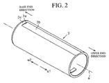
- the outer tube 3 is a cylindrical member, and a planar portion 3b is formed in the outer peripheral surface of the outer tube 3 while a curved surface portion 3c that forms the outer edge of the cylinder is left at the base end portion side.
- the planar portion 3b is formed by cutting out a portion of the outer peripheral surface into a planar shape from the upper end portion toward the base end portion. That is, the planar portion 3b and the curved surface portion 3c are arranged side by side in a direction of an axis m.
- the projecting portion 3a is formed of a step portion between these planar portion 3b and curved surface portion 3c.
- the projecting portion 3a When the projecting portion 3a is formed of the step portion between the planar portion 3b and the curved surface portion 3c as described above, the projecting portion 3a may be formed by just forming the planar portion 3b in the outer peripheral surface of the outer tube 3. Therefore, it is possible to easily form the projecting portion 3a.
- the planar portion 3b is a portion pressed by the tensioner bushings 4a and 4b.
- the portion pressed by the tensioner bushings 4a and 4b is formed in a planar shape in this way to thereby increase the pressure receiving area of the outer tube 3.
- a force acting from the tensioner bushings 4a and 4b on the outer tube 3 may be increased. Therefore, the stiffness of the steering column increases.
- the projecting portion 3a functions as a portion that restricts movement of the outer tube 3 in the direction indicated by the arrow a1 when the outer tube 3 moves in the direction indicated by the arrow a1 due to extending or retracting action.
- the outside diameter of the outer tube 3 is substantially equal to or slightly smaller than the inside diameter of each of bearings 2a and 2b shown in FIG. 1 . Therefore, a slight gap is formed between the inner peripheral surface of each of the bearings 2a and 2b and the planar portion 3b.
- a movement restricting structure that restricts movement of the outer tube 3 in the direction indicated by the arrow a1 is formed of the projecting portion 3a of the outer tube 3 and the tensioner bushing 4a.
- the movement restricting structure prevents the outer tube 3 from slipping off from the housing 1.
- the retaining member of the existing art may be omitted. Therefore, the axial length of the steering column may be reduced by the length of the retaining member.
- the bolt for assembling the retaining member to the housing may also be omitted in addition to the retaining member. Therefore, the number of components may be reduced. As a result, it is possible to reduce the weight and cost of the steering column.
- the tensioner bushing 4a is used as a member that restricts movement of the projecting portion 3a. Therefore, a member that restricts movement of the projecting portion 3a need not be provided in the housing 1. Therefore, it is possible to simplify the structure of the steering column and reduce the cost of the steering column.
- the above-described embodiment may be modified into the following alternative embodiments.
- the axial length of the steering column is reduced by the length of the omitted retaining member.
- a structure in which the retaining member is just omitted may be employed. With this configuration, it is possible to obtain an advantageous effect that the E/A stroke Ls2 is made longer than the E/A stroke Ls1 without reducing the axial length of the steering column.
- the projecting portion 3a is formed of the step portion between the planar portion 3b and the curved surface portion 3c that are formed in the outer peripheral surface of the outer tube 3.
- a planar portion 3d that extends from the upper end portion toward the base end portion may be formed in the outer peripheral surface of the outer tube 3 and then a projecting portion 3e may be formed on the planar portion 3d.
- the projecting portion 3a is brought into contact with the tensioner bushing 4a that serves as a pressing member to thereby restrict movement of the outer tube 3.
- the projection amount of the projecting portion 3a may be adjusted, and then the projecting portion 3a may be brought into contact with the bearing 2a to thereby restrict movement of the outer tube 3.
- a projecting portion may be formed on the outer peripheral surface of the center portion of the outer tube 3 so as to be located between the tensioner bushings 4a and 4b, and then the projecting portion is brought into contact with the tensioner bushing 4b to thereby restrict movement of the outer tube 3.
- a projecting portion may be newly formed on the inner wall surface of the housing 1and then the newly formed projecting portion may be used to restrict movement of the projecting portion 3a.
- a method of newly forming a projecting portion on the inner wall surface of the housing 1 may be an appropriately employed method, such as forming a projecting portion by machining the inner wall surface of the housing 1 and embedding a bolt in the inner wall surface of the housing 1.
- any movement restricting structure may be employed as long as the movement restricting structure is formed of a projecting portion provided on the outer peripheral surface of the outer tube 3 so as to project into the gap between the housing 1 and the outer tube 3 and a projecting portion provided on the inner wall surface of the housing 1 so as to project into the gap and the projecting portion of the outer tube 3 contacts the projecting portion of the housing 1 to thereby restrict movement of the outer tube 3 in the direction indicated by the arrow a1.
- the projecting portion provided on the outer peripheral surface of the outer tube 3 is brought into contact with the projecting portion provided on the inner wall surface of the housing 1 to thereby restrict movement of the outer tube 3.
- a groove 1b may be formed in the inner wall surface of the housing 1
- a projecting portion 3f to be inserted in the groove 1b may be formed on the outer peripheral surface of the outer tube 3
- the projecting portion 3f may contact the inner wall surface of the groove 1b in the direction indicated by the arrow a1 to thereby restrict movement of the outer tube 3 in the direction indicated by the arrow al.
- any movement restricting structure may be employed as long as the movement restricting structure is provided at a portion at which the inner wall surface of the housing 1 faces the outer wall surface of the outer tube 3 and restricts movement of the outer tube 3 in the direction of the axis m.
- a steering column is configured in such a manner that the projecting portion of the housing is formed by machining the inner peripheral surface of the housing. With the above configuration, the projecting portion of the housing may be easily formed.
Landscapes
- Engineering & Computer Science (AREA)
- Chemical & Material Sciences (AREA)
- Combustion & Propulsion (AREA)
- Transportation (AREA)
- Mechanical Engineering (AREA)
- Steering Controls (AREA)
Claims (4)
- Lenksäule mit:einem Innenrohr (6), das eine Lenkwelle (8) beherbergt, die eine Drehwelle eines Lenkrads eines Fahrzeugs ist, und das sich in eine axiale Richtung der Lenkwelle (8) zusammen mit der Lenkwelle (8) bewegt;einem Außenrohr (3), das von einem Gehäuse (1) gehalten wird, das von einem Fahrzeugaufbau gestützt ist, so dass es in die axiale Richtung bewegbar ist, und das mit dem Innenrohr (6) gekoppelt ist;einem Teleskopmechanismus, der eine Position des Lenkrads in der axialen Richtung einstellt, indem sich das Innenrohr (6) und das Außenrohr (3) in einem gekoppelten Zustand zusammen mit der Lenkwelle (8) in die axiale Richtung bewegen; undeinem Aufprallabsorbtionsmechanismus, der eine Aufprallenergie absorbiert, wenn das Koppeln des Innenrohrs (6) und des Außenrohrs (3) aufgehoben wird, um die Lenkwelle (8) um einen vorherbestimmten Betrag (Ls2) in die axiale Richtung auf eine auf die Lenkwelle (8) oder das Gehäuse (1) aufgebrachte Kraft hin zurückzuziehen, die eine Kopplungskraft übersteigt, die das Innenrohr (6) und das Außenrohr (3) miteinander koppelt, dadurch gekennzeichnet, dassdie Lenksäule eine Bewegungsbeschränkungsstruktur hat, die eine Bewegung des Außenrohrs (3) in die axiale Richtung an einem Abschnitt beschränkt, an dem eine innere Umfangsfläche des Gehäuses (1) einer äußeren Umfangsfläche des Außenrohrs (3) zugewandt ist.
- Lenksäule nach Anspruch 1, wobei:die Bewegungsbeschränkungsstruktur aus einem vorstehenden Abschnitt (3a), der an der äußeren Umfangsfläche des Außenrohrs (3) vorgesehen ist, so dass er in einen Spalt zwischen dem Gehäuse (1) und dem Außenohr (3) vorsteht, und einem vorstehenden Abschnitt, der an einer inneren Umfangsfläche des Gehäuses (1) vorgesehen ist, so dass er in den Spalt vorsteht; undeine Bewegung des Außenrohrs (3) in die axiale Richtung beschränkt ist, wenn der vorstehende Abschnitt (3a) des Außenrohrs (3) den vorstehenden Abschnitt des Gehäuses (1) berührt.
- Lenksäule nach Anspruch 2, wobei:das Gehäuse (1) ein Presselement (4a) umfasst, das angeordnet ist, so dass es von der inneren Umfangsfläche des Gehäuses (1) vorsteht, die äußere Umfangsfläche des Außenrohrs (3) berührt und die äußere Umfangsfläche des Außenrohrs (3) presst; unddas Presselement (4a) den vorstehenden Abschnitt des Gehäuses (1) darstellt.
- Lenksäule nach Anspruch 3, wobei:das Außenrohr (3) ein zylindrisches Element ist und auf eine solche Art und Weise ausgebildet ist, das ein gebogener Flächenabschnitt (3c), der einen Außenrand der zylindrischen Form ausbildet, und ein ebener Abschnitt (3b), der durch Ausschneiden eines Abschnitts der äußeren Umfangsfläche in eine ebene Form ausgebildet ist, nebeneinander in der axialen Richtung auf der äußeren Umfangsfläche des Außenrohrs (3) angeordnet sind; undder vorstehende Abschnitt (3a) des Außenrohrs (3) aus einem Stufenabschnitt ausgebildet ist, der zwischen dem gebogenen Flächenabschnitt (3c) und dem ebenen Abschnitt (3b) ausgebildet ist.
Applications Claiming Priority (1)
| Application Number | Priority Date | Filing Date | Title |
|---|---|---|---|
| JP2009191933A JP2011042262A (ja) | 2009-08-21 | 2009-08-21 | ステアリングコラム |
Publications (3)
| Publication Number | Publication Date |
|---|---|
| EP2287063A2 EP2287063A2 (de) | 2011-02-23 |
| EP2287063A3 EP2287063A3 (de) | 2012-03-21 |
| EP2287063B1 true EP2287063B1 (de) | 2013-04-03 |
Family
ID=43037732
Family Applications (1)
| Application Number | Title | Priority Date | Filing Date |
|---|---|---|---|
| EP10173384A Not-in-force EP2287063B1 (de) | 2009-08-21 | 2010-08-19 | Lenksäule |
Country Status (4)
| Country | Link |
|---|---|
| US (1) | US20110041643A1 (de) |
| EP (1) | EP2287063B1 (de) |
| JP (1) | JP2011042262A (de) |
| CN (1) | CN101992800A (de) |
Families Citing this family (14)
| Publication number | Priority date | Publication date | Assignee | Title |
|---|---|---|---|---|
| JP5146474B2 (ja) * | 2010-02-22 | 2013-02-20 | 日本精工株式会社 | ステアリングコラム装置とその組立方法 |
| JP5429379B2 (ja) * | 2011-05-30 | 2014-02-26 | 日本精工株式会社 | ステアリング装置 |
| DE102011112079B4 (de) * | 2011-09-01 | 2014-02-06 | Audi Ag | Lenkradanordnung für ein Kraftfahrzeug |
| JP5811735B2 (ja) * | 2011-09-26 | 2015-11-11 | アイシン精機株式会社 | 車両のステアリング装置 |
| US20130133461A1 (en) * | 2011-11-30 | 2013-05-30 | Nexteer (Beijing) Technology Co., Ltd. | Energy absorbing steering column assembly |
| JP6179347B2 (ja) * | 2013-10-25 | 2017-08-16 | アイシン精機株式会社 | 車両のステアリング装置 |
| CN104554421A (zh) * | 2014-12-30 | 2015-04-29 | 耐世特汽车系统(苏州)有限公司 | 一种转向管柱护管 |
| DE102015000027A1 (de) | 2015-01-08 | 2016-07-14 | Thyssenkrupp Ag | Lenksäule mit flexibel montierbarem Lagersitz |
| DE102015002889B3 (de) * | 2015-03-09 | 2016-05-12 | Thyssenkrupp Ag | Verstellbare Lenksäule mit verbesserter Steifigkeit |
| DE102015216326B4 (de) * | 2015-08-26 | 2016-09-08 | Thyssenkrupp Ag | Motorisch verstellbare Lenksäule für ein Kraftfahrzeug |
| US10654510B2 (en) * | 2017-08-28 | 2020-05-19 | Fuji Kiko Co., Ltd. | Electric steering column apparatus |
| CN109501852B (zh) * | 2018-12-19 | 2021-07-30 | 芜湖世特瑞转向系统有限公司 | 电动四向可调转向管柱 |
| FR3105773B1 (fr) * | 2019-12-31 | 2025-04-25 | Robert Bosch Automotive Steering Vendome | fourreau de colonne de direction comportant un Système de réglage d’une position relative entre deux tubes |
| WO2022269932A1 (ja) | 2021-06-25 | 2022-12-29 | 株式会社ジェイテクト | ステアリングコラム装置 |
Family Cites Families (11)
| Publication number | Priority date | Publication date | Assignee | Title |
|---|---|---|---|---|
| JPS56120458A (en) * | 1980-02-25 | 1981-09-21 | Aisin Seiki Co Ltd | Mechanism for adjusting axial position of steering wheel |
| JPS5947574U (ja) * | 1982-09-24 | 1984-03-29 | トヨタ自動車株式会社 | テレスコピツクステアリング装置 |
| US4805478A (en) * | 1987-06-26 | 1989-02-21 | General Motors Corporation | Steering column for vehicle with multitube energy absorbing mast jacket |
| US5267480A (en) * | 1992-07-10 | 1993-12-07 | Douglas Autotech Corporation | Telescoping column |
| DE19504036C1 (de) * | 1995-02-08 | 1996-06-27 | Lemfoerder Metallwaren Ag | Sicherheitslenkwelle |
| JP2942496B2 (ja) * | 1996-03-07 | 1999-08-30 | 株式会社椿本チエイン | ねじ式直線作動機の廻り止め機構 |
| JP2002046625A (ja) * | 2000-08-04 | 2002-02-12 | Nsk Ltd | テレスコピックステアリングコラム |
| JP4868213B2 (ja) * | 2005-12-21 | 2012-02-01 | アイシン精機株式会社 | エネルギー吸収ステアリングコラム |
| JP5125253B2 (ja) * | 2007-06-26 | 2013-01-23 | アイシン精機株式会社 | 車両のステアリング装置 |
| JP2009107540A (ja) * | 2007-10-31 | 2009-05-21 | Nsk Ltd | 位置調整式ステアリング装置 |
| DE102007060149A1 (de) * | 2007-12-13 | 2009-06-18 | GM Global Technology Operations, Inc., Detroit | Teleskopierbare Lenkspindelanordnung |
-
2009
- 2009-08-21 JP JP2009191933A patent/JP2011042262A/ja active Pending
-
2010
- 2010-07-30 US US12/847,309 patent/US20110041643A1/en not_active Abandoned
- 2010-08-19 EP EP10173384A patent/EP2287063B1/de not_active Not-in-force
- 2010-08-19 CN CN2010102594326A patent/CN101992800A/zh active Pending
Also Published As
| Publication number | Publication date |
|---|---|
| EP2287063A2 (de) | 2011-02-23 |
| EP2287063A3 (de) | 2012-03-21 |
| CN101992800A (zh) | 2011-03-30 |
| JP2011042262A (ja) | 2011-03-03 |
| US20110041643A1 (en) | 2011-02-24 |
Similar Documents
| Publication | Publication Date | Title |
|---|---|---|
| EP2287063B1 (de) | Lenksäule | |
| US8408089B2 (en) | Energy absorbing steering column | |
| JP2019127176A (ja) | ステアリング装置 | |
| EP2025576B1 (de) | Lenkradpositions-Einstellungsvorrichtung | |
| JP6429077B2 (ja) | ステアリング装置 | |
| US7527295B2 (en) | Energy absorbing steering column | |
| KR20160106236A (ko) | 자동차의 조향컬럼 | |
| CN110077451B (zh) | 转向装置 | |
| US10875568B2 (en) | Steering column for vehicle | |
| KR20180022289A (ko) | 자동차 스티어링 컬럼의 텔레스코픽 래치 장치 | |
| JP5228984B2 (ja) | エネルギー吸収ステアリングコラム | |
| EP2292494A1 (de) | Stossdämpfende lenkungsanordnung | |
| JP5268027B2 (ja) | エネルギー吸収ステアリングコラム | |
| WO2005123484A1 (ja) | ラックストロークエンドの衝撃緩和装置 | |
| JP6179347B2 (ja) | 車両のステアリング装置 | |
| JP6132147B2 (ja) | ラックガイド装置 | |
| JP3938314B2 (ja) | ステアリング装置 | |
| JP6481374B2 (ja) | エネルギー吸収ステアリングコラム | |
| KR102246687B1 (ko) | 자동차의 조향컬럼 | |
| KR102245792B1 (ko) | 전동식 조향장치 | |
| JP3930253B2 (ja) | 衝撃吸収式ステアリング装置 | |
| JPH082025Y2 (ja) | 衝撃吸収式ステアリングコラム装置 | |
| JPH0924842A (ja) | 衝撃吸収式ステアリング装置 | |
| KR20200105132A (ko) | 자동차의 조향컬럼 | |
| JP5251968B2 (ja) | 十字軸自在継手 |
Legal Events
| Date | Code | Title | Description |
|---|---|---|---|
| PUAI | Public reference made under article 153(3) epc to a published international application that has entered the european phase |
Free format text: ORIGINAL CODE: 0009012 |
|
| AK | Designated contracting states |
Kind code of ref document: A2 Designated state(s): AL AT BE BG CH CY CZ DE DK EE ES FI FR GB GR HR HU IE IS IT LI LT LU LV MC MK MT NL NO PL PT RO SE SI SK SM TR |
|
| AX | Request for extension of the european patent |
Extension state: BA ME RS |
|
| PUAL | Search report despatched |
Free format text: ORIGINAL CODE: 0009013 |
|
| AK | Designated contracting states |
Kind code of ref document: A3 Designated state(s): AL AT BE BG CH CY CZ DE DK EE ES FI FR GB GR HR HU IE IS IT LI LT LU LV MC MK MT NL NO PL PT RO SE SI SK SM TR |
|
| AX | Request for extension of the european patent |
Extension state: BA ME RS |
|
| RIC1 | Information provided on ipc code assigned before grant |
Ipc: B62D 1/185 20060101AFI20120215BHEP Ipc: B62D 1/19 20060101ALI20120215BHEP |
|
| 17P | Request for examination filed |
Effective date: 20120712 |
|
| GRAP | Despatch of communication of intention to grant a patent |
Free format text: ORIGINAL CODE: EPIDOSNIGR1 |
|
| GRAS | Grant fee paid |
Free format text: ORIGINAL CODE: EPIDOSNIGR3 |
|
| GRAA | (expected) grant |
Free format text: ORIGINAL CODE: 0009210 |
|
| AK | Designated contracting states |
Kind code of ref document: B1 Designated state(s): AL AT BE BG CH CY CZ DE DK EE ES FI FR GB GR HR HU IE IS IT LI LT LU LV MC MK MT NL NO PL PT RO SE SI SK SM TR |
|
| REG | Reference to a national code |
Ref country code: GB Ref legal event code: FG4D |
|
| REG | Reference to a national code |
Ref country code: CH Ref legal event code: EP Ref country code: AT Ref legal event code: REF Ref document number: 604520 Country of ref document: AT Kind code of ref document: T Effective date: 20130415 |
|
| REG | Reference to a national code |
Ref country code: IE Ref legal event code: FG4D |
|
| REG | Reference to a national code |
Ref country code: DE Ref legal event code: R096 Ref document number: 602010006028 Country of ref document: DE Effective date: 20130606 |
|
| REG | Reference to a national code |
Ref country code: AT Ref legal event code: MK05 Ref document number: 604520 Country of ref document: AT Kind code of ref document: T Effective date: 20130403 |
|
| PG25 | Lapsed in a contracting state [announced via postgrant information from national office to epo] |
Ref country code: SI Free format text: LAPSE BECAUSE OF FAILURE TO SUBMIT A TRANSLATION OF THE DESCRIPTION OR TO PAY THE FEE WITHIN THE PRESCRIBED TIME-LIMIT Effective date: 20130403 |
|
| REG | Reference to a national code |
Ref country code: NL Ref legal event code: VDEP Effective date: 20130403 |
|
| REG | Reference to a national code |
Ref country code: LT Ref legal event code: MG4D |
|
| PG25 | Lapsed in a contracting state [announced via postgrant information from national office to epo] |
Ref country code: PT Free format text: LAPSE BECAUSE OF FAILURE TO SUBMIT A TRANSLATION OF THE DESCRIPTION OR TO PAY THE FEE WITHIN THE PRESCRIBED TIME-LIMIT Effective date: 20130805 Ref country code: BE Free format text: LAPSE BECAUSE OF FAILURE TO SUBMIT A TRANSLATION OF THE DESCRIPTION OR TO PAY THE FEE WITHIN THE PRESCRIBED TIME-LIMIT Effective date: 20130403 Ref country code: NO Free format text: LAPSE BECAUSE OF FAILURE TO SUBMIT A TRANSLATION OF THE DESCRIPTION OR TO PAY THE FEE WITHIN THE PRESCRIBED TIME-LIMIT Effective date: 20130703 Ref country code: FI Free format text: LAPSE BECAUSE OF FAILURE TO SUBMIT A TRANSLATION OF THE DESCRIPTION OR TO PAY THE FEE WITHIN THE PRESCRIBED TIME-LIMIT Effective date: 20130403 Ref country code: IS Free format text: LAPSE BECAUSE OF FAILURE TO SUBMIT A TRANSLATION OF THE DESCRIPTION OR TO PAY THE FEE WITHIN THE PRESCRIBED TIME-LIMIT Effective date: 20130803 Ref country code: ES Free format text: LAPSE BECAUSE OF FAILURE TO SUBMIT A TRANSLATION OF THE DESCRIPTION OR TO PAY THE FEE WITHIN THE PRESCRIBED TIME-LIMIT Effective date: 20130714 Ref country code: AT Free format text: LAPSE BECAUSE OF FAILURE TO SUBMIT A TRANSLATION OF THE DESCRIPTION OR TO PAY THE FEE WITHIN THE PRESCRIBED TIME-LIMIT Effective date: 20130403 Ref country code: NL Free format text: LAPSE BECAUSE OF FAILURE TO SUBMIT A TRANSLATION OF THE DESCRIPTION OR TO PAY THE FEE WITHIN THE PRESCRIBED TIME-LIMIT Effective date: 20130403 Ref country code: GR Free format text: LAPSE BECAUSE OF FAILURE TO SUBMIT A TRANSLATION OF THE DESCRIPTION OR TO PAY THE FEE WITHIN THE PRESCRIBED TIME-LIMIT Effective date: 20130704 Ref country code: LT Free format text: LAPSE BECAUSE OF FAILURE TO SUBMIT A TRANSLATION OF THE DESCRIPTION OR TO PAY THE FEE WITHIN THE PRESCRIBED TIME-LIMIT Effective date: 20130403 Ref country code: SE Free format text: LAPSE BECAUSE OF FAILURE TO SUBMIT A TRANSLATION OF THE DESCRIPTION OR TO PAY THE FEE WITHIN THE PRESCRIBED TIME-LIMIT Effective date: 20130403 |
|
| PG25 | Lapsed in a contracting state [announced via postgrant information from national office to epo] |
Ref country code: HR Free format text: LAPSE BECAUSE OF FAILURE TO SUBMIT A TRANSLATION OF THE DESCRIPTION OR TO PAY THE FEE WITHIN THE PRESCRIBED TIME-LIMIT Effective date: 20130403 Ref country code: BG Free format text: LAPSE BECAUSE OF FAILURE TO SUBMIT A TRANSLATION OF THE DESCRIPTION OR TO PAY THE FEE WITHIN THE PRESCRIBED TIME-LIMIT Effective date: 20130703 Ref country code: PL Free format text: LAPSE BECAUSE OF FAILURE TO SUBMIT A TRANSLATION OF THE DESCRIPTION OR TO PAY THE FEE WITHIN THE PRESCRIBED TIME-LIMIT Effective date: 20130403 Ref country code: CY Free format text: LAPSE BECAUSE OF FAILURE TO SUBMIT A TRANSLATION OF THE DESCRIPTION OR TO PAY THE FEE WITHIN THE PRESCRIBED TIME-LIMIT Effective date: 20130403 Ref country code: LV Free format text: LAPSE BECAUSE OF FAILURE TO SUBMIT A TRANSLATION OF THE DESCRIPTION OR TO PAY THE FEE WITHIN THE PRESCRIBED TIME-LIMIT Effective date: 20130403 |
|
| PG25 | Lapsed in a contracting state [announced via postgrant information from national office to epo] |
Ref country code: SK Free format text: LAPSE BECAUSE OF FAILURE TO SUBMIT A TRANSLATION OF THE DESCRIPTION OR TO PAY THE FEE WITHIN THE PRESCRIBED TIME-LIMIT Effective date: 20130403 Ref country code: EE Free format text: LAPSE BECAUSE OF FAILURE TO SUBMIT A TRANSLATION OF THE DESCRIPTION OR TO PAY THE FEE WITHIN THE PRESCRIBED TIME-LIMIT Effective date: 20130403 Ref country code: CZ Free format text: LAPSE BECAUSE OF FAILURE TO SUBMIT A TRANSLATION OF THE DESCRIPTION OR TO PAY THE FEE WITHIN THE PRESCRIBED TIME-LIMIT Effective date: 20130403 Ref country code: DK Free format text: LAPSE BECAUSE OF FAILURE TO SUBMIT A TRANSLATION OF THE DESCRIPTION OR TO PAY THE FEE WITHIN THE PRESCRIBED TIME-LIMIT Effective date: 20130403 |
|
| PLBE | No opposition filed within time limit |
Free format text: ORIGINAL CODE: 0009261 |
|
| STAA | Information on the status of an ep patent application or granted ep patent |
Free format text: STATUS: NO OPPOSITION FILED WITHIN TIME LIMIT |
|
| PG25 | Lapsed in a contracting state [announced via postgrant information from national office to epo] |
Ref country code: IT Free format text: LAPSE BECAUSE OF FAILURE TO SUBMIT A TRANSLATION OF THE DESCRIPTION OR TO PAY THE FEE WITHIN THE PRESCRIBED TIME-LIMIT Effective date: 20130403 Ref country code: RO Free format text: LAPSE BECAUSE OF FAILURE TO SUBMIT A TRANSLATION OF THE DESCRIPTION OR TO PAY THE FEE WITHIN THE PRESCRIBED TIME-LIMIT Effective date: 20130403 |
|
| REG | Reference to a national code |
Ref country code: DE Ref legal event code: R119 Ref document number: 602010006028 Country of ref document: DE |
|
| 26N | No opposition filed |
Effective date: 20140106 |
|
| REG | Reference to a national code |
Ref country code: DE Ref legal event code: R097 Ref document number: 602010006028 Country of ref document: DE Effective date: 20140106 |
|
| PG25 | Lapsed in a contracting state [announced via postgrant information from national office to epo] |
Ref country code: MC Free format text: LAPSE BECAUSE OF FAILURE TO SUBMIT A TRANSLATION OF THE DESCRIPTION OR TO PAY THE FEE WITHIN THE PRESCRIBED TIME-LIMIT Effective date: 20130403 Ref country code: DE Free format text: LAPSE BECAUSE OF NON-PAYMENT OF DUE FEES Effective date: 20140301 |
|
| REG | Reference to a national code |
Ref country code: IE Ref legal event code: MM4A |
|
| REG | Reference to a national code |
Ref country code: DE Ref legal event code: R119 Ref document number: 602010006028 Country of ref document: DE Effective date: 20140301 |
|
| REG | Reference to a national code |
Ref country code: FR Ref legal event code: ST Effective date: 20140430 |
|
| PG25 | Lapsed in a contracting state [announced via postgrant information from national office to epo] |
Ref country code: IE Free format text: LAPSE BECAUSE OF NON-PAYMENT OF DUE FEES Effective date: 20130819 |
|
| PG25 | Lapsed in a contracting state [announced via postgrant information from national office to epo] |
Ref country code: FR Free format text: LAPSE BECAUSE OF NON-PAYMENT OF DUE FEES Effective date: 20130902 |
|
| REG | Reference to a national code |
Ref country code: CH Ref legal event code: PL |
|
| GBPC | Gb: european patent ceased through non-payment of renewal fee |
Effective date: 20140819 |
|
| PG25 | Lapsed in a contracting state [announced via postgrant information from national office to epo] |
Ref country code: CH Free format text: LAPSE BECAUSE OF NON-PAYMENT OF DUE FEES Effective date: 20140831 Ref country code: LI Free format text: LAPSE BECAUSE OF NON-PAYMENT OF DUE FEES Effective date: 20140831 |
|
| PG25 | Lapsed in a contracting state [announced via postgrant information from national office to epo] |
Ref country code: SM Free format text: LAPSE BECAUSE OF FAILURE TO SUBMIT A TRANSLATION OF THE DESCRIPTION OR TO PAY THE FEE WITHIN THE PRESCRIBED TIME-LIMIT Effective date: 20130403 |
|
| PG25 | Lapsed in a contracting state [announced via postgrant information from national office to epo] |
Ref country code: MT Free format text: LAPSE BECAUSE OF FAILURE TO SUBMIT A TRANSLATION OF THE DESCRIPTION OR TO PAY THE FEE WITHIN THE PRESCRIBED TIME-LIMIT Effective date: 20130403 Ref country code: TR Free format text: LAPSE BECAUSE OF FAILURE TO SUBMIT A TRANSLATION OF THE DESCRIPTION OR TO PAY THE FEE WITHIN THE PRESCRIBED TIME-LIMIT Effective date: 20130403 |
|
| PG25 | Lapsed in a contracting state [announced via postgrant information from national office to epo] |
Ref country code: MK Free format text: LAPSE BECAUSE OF FAILURE TO SUBMIT A TRANSLATION OF THE DESCRIPTION OR TO PAY THE FEE WITHIN THE PRESCRIBED TIME-LIMIT Effective date: 20130403 Ref country code: GB Free format text: LAPSE BECAUSE OF NON-PAYMENT OF DUE FEES Effective date: 20140819 Ref country code: HU Free format text: LAPSE BECAUSE OF FAILURE TO SUBMIT A TRANSLATION OF THE DESCRIPTION OR TO PAY THE FEE WITHIN THE PRESCRIBED TIME-LIMIT; INVALID AB INITIO Effective date: 20100819 Ref country code: LU Free format text: LAPSE BECAUSE OF NON-PAYMENT OF DUE FEES Effective date: 20130819 |
|
| PG25 | Lapsed in a contracting state [announced via postgrant information from national office to epo] |
Ref country code: AL Free format text: LAPSE BECAUSE OF FAILURE TO SUBMIT A TRANSLATION OF THE DESCRIPTION OR TO PAY THE FEE WITHIN THE PRESCRIBED TIME-LIMIT Effective date: 20130403 |