EP2287480B1 - Bewegungsführungsvorrichtung - Google Patents
Bewegungsführungsvorrichtung Download PDFInfo
- Publication number
- EP2287480B1 EP2287480B1 EP10013280A EP10013280A EP2287480B1 EP 2287480 B1 EP2287480 B1 EP 2287480B1 EP 10013280 A EP10013280 A EP 10013280A EP 10013280 A EP10013280 A EP 10013280A EP 2287480 B1 EP2287480 B1 EP 2287480B1
- Authority
- EP
- European Patent Office
- Prior art keywords
- ball
- ball rolling
- scoop section
- load
- section
- Prior art date
- Legal status (The legal status is an assumption and is not a legal conclusion. Google has not performed a legal analysis and makes no representation as to the accuracy of the status listed.)
- Expired - Lifetime
Links
Images



Classifications
-
- F—MECHANICAL ENGINEERING; LIGHTING; HEATING; WEAPONS; BLASTING
- F16—ENGINEERING ELEMENTS AND UNITS; GENERAL MEASURES FOR PRODUCING AND MAINTAINING EFFECTIVE FUNCTIONING OF MACHINES OR INSTALLATIONS; THERMAL INSULATION IN GENERAL
- F16C—SHAFTS; FLEXIBLE SHAFTS; ELEMENTS OR CRANKSHAFT MECHANISMS; ROTARY BODIES OTHER THAN GEARING ELEMENTS; BEARINGS
- F16C29/00—Bearings for parts moving only linearly
- F16C29/04—Ball or roller bearings
- F16C29/06—Ball or roller bearings in which the rolling bodies circulate partly without carrying load
-
- F—MECHANICAL ENGINEERING; LIGHTING; HEATING; WEAPONS; BLASTING
- F16—ENGINEERING ELEMENTS AND UNITS; GENERAL MEASURES FOR PRODUCING AND MAINTAINING EFFECTIVE FUNCTIONING OF MACHINES OR INSTALLATIONS; THERMAL INSULATION IN GENERAL
- F16C—SHAFTS; FLEXIBLE SHAFTS; ELEMENTS OR CRANKSHAFT MECHANISMS; ROTARY BODIES OTHER THAN GEARING ELEMENTS; BEARINGS
- F16C29/00—Bearings for parts moving only linearly
- F16C29/04—Ball or roller bearings
- F16C29/06—Ball or roller bearings in which the rolling bodies circulate partly without carrying load
- F16C29/0633—Ball or roller bearings in which the rolling bodies circulate partly without carrying load with a bearing body defining a U-shaped carriage, i.e. surrounding a guide rail or track on three sides
- F16C29/0635—Ball or roller bearings in which the rolling bodies circulate partly without carrying load with a bearing body defining a U-shaped carriage, i.e. surrounding a guide rail or track on three sides whereby the return paths are provided as bores in a main body of the U-shaped carriage, e.g. the main body of the U-shaped carriage is a single part with end caps provided at each end
- F16C29/0638—Ball or roller bearings in which the rolling bodies circulate partly without carrying load with a bearing body defining a U-shaped carriage, i.e. surrounding a guide rail or track on three sides whereby the return paths are provided as bores in a main body of the U-shaped carriage, e.g. the main body of the U-shaped carriage is a single part with end caps provided at each end with balls
- F16C29/0642—Ball or roller bearings in which the rolling bodies circulate partly without carrying load with a bearing body defining a U-shaped carriage, i.e. surrounding a guide rail or track on three sides whereby the return paths are provided as bores in a main body of the U-shaped carriage, e.g. the main body of the U-shaped carriage is a single part with end caps provided at each end with balls with four rows of balls
-
- F—MECHANICAL ENGINEERING; LIGHTING; HEATING; WEAPONS; BLASTING
- F16—ENGINEERING ELEMENTS AND UNITS; GENERAL MEASURES FOR PRODUCING AND MAINTAINING EFFECTIVE FUNCTIONING OF MACHINES OR INSTALLATIONS; THERMAL INSULATION IN GENERAL
- F16C—SHAFTS; FLEXIBLE SHAFTS; ELEMENTS OR CRANKSHAFT MECHANISMS; ROTARY BODIES OTHER THAN GEARING ELEMENTS; BEARINGS
- F16C29/00—Bearings for parts moving only linearly
- F16C29/04—Ball or roller bearings
- F16C29/06—Ball or roller bearings in which the rolling bodies circulate partly without carrying load
- F16C29/0602—Details of the bearing body or carriage or parts thereof, e.g. methods for manufacturing or assembly
- F16C29/0609—Details of the bearing body or carriage or parts thereof, e.g. methods for manufacturing or assembly of the ends of the bearing body or carriage where the rolling elements change direction, e.g. end caps
Definitions
- the present invention relates to a motion guide device, such as a linear guide or a ball spline in which a moving member moves relative to a raceway member.
- a motion guide device in which a ball that rolls in a ball rolling groove of a raceway member is scooped by a scoop section of a moving member so as to be introduced into a no-load ball return path.
- a linear guide one type of a motion guide device, is provided with a raceway rail in which a plurality of ball rolling grooves are formed, extending parallel to each other, and a saddle-shaped moving block which is assembled so as to be slidably movable along the raceway rail through a number of rolling bodies, such as balls.
- the moving block is formed with a plurality of load ball rolling grooves opposed to the ball rolling grooves in the raceway rail, and no-load ball return paths each of which connects one end of the load ball rolling groove and the other end of the load ball rolling groove.
- a pair of end plates is attached to both ends of the moving block in its moving direction.
- Each of the balls that rolls in the ball rolling groove in the raceway rail is scooped from the ball rolling groove by the scoop section at a lower end of the end plate for entry into the no-load ball return path.
- the ball that has circulated through the no-load ball return path again enters a load ball rolling path (defined between the ball rolling groove in the raceway rail and the load ball rolling groove in the moving block), being pushed by the balls that follow.
- Patent Document 1 Japanese Patent Laid-Open No. 2004-068880
- Damages at the scoop section are caused when each ball is discharged from the end plate for entry into the load ball rolling path, and when each ball is discharged from the load ball rolling path for entry into the end plate.
- Fig. 13 illustrates a state where a ball 1 is discharged from an end plate 2 and enters a load ball rolling path 3, and a state where the ball 1 is discharged from the load ball rolling path 3 and enters the end plate 2.
- the ball 1 is discharged from the end plate 2 and enters the load ball rolling path 3
- the ball 1 is deformed, being compressed between a ball rolling groove 5a of a raceway rail 5 and a load ball rolling groove 4a of a moving block 4.
- Higher moving speed of the ball 1 will make the entry of the ball 1 into the load ball rolling path 3 more difficult.
- the following pushing balls are zigzagged so that a ball 1a proximate to a scoop section is pushed outward.
- This ball 1a which is pushed outside, has been the potential cause of deformation of and thus damages on a scoop portion 2a.
- the present invention has an object of providing a motion guide device having an improved scoop section structure which barely induces damage thereto when a moving member is moved at high speed.
- a motion guide device comprises the features of claim 1.
- Fig. 1 illustrates a linear guide as a motion guide device in an embodiment of the present invention.
- This linear guide is provided with an elongated raceway rail 11 extending linearly and serving a raceway member, and a saddle-shaped moving block 12 serving as a moving member, which is assembled so as to be slidably movable relative to the raceway rail 11.
- a number of balls 13 capable of rolling movement are intervened between the raceway rail 11 and the moving block 12.
- the raceway rail 11 is formed to have a substantially rectangular cross-section, with a total of four ball rolling grooves 11a being formed in upper portions of left and right side faces and in opposed ends of an upper surface of the raceway rail 11.
- Each of the ball rolling grooves 11a extends in a longitudinal direction of the raceway rail 11 and formed into a circular arc grooved shape with its cross-section consisting of a single arc.
- the moving block 12 is provided with a central portion 12a being opposed to the upper surface of the raceway rail 11, and side wall portions 12b, 12b, which extend downward from lateral sides of the central portion 12a so as to be opposed to the respective left and right side faces of the raceway rail 11.
- the entirety of the moving block 12 is formed into a shape of a saddle.
- the moving block 12 is provided with a steel moving block body 14 and a pair of end plates 15 which are mounted on lateral end faces of the moving block body 14 in its traveling direction.
- a load ball rolling groove 14a is formed in the moving block body 14 so as to face the ball rolling groove 11a of the raceway rail 11.
- the load ball rolling groove 14a is also formed into a circular arc grooved shape consisting of a single arc, totaling four in number so as to be opposed to each of the ball rolling grooves 11a of the raceway rail 11.
- the balls 13 roll and move between the ball rolling groove 11a of the raceway rail 11 and the load ball rolling groove 14a of the moving block body 14, being imposed with load.
- a ball escape path 17 made up of a through hole is formed extending parallel to each of the load ball rolling grooves 14a with a predetermined interval therebetween.
- the moving block body 14 is also integrally formed with an R-shaped piece 19, which connects between the load ball rolling groove 14a and the ball escape path 17 and constitutes an inner periphery of a U-shaped direction changing path 21 (refer to Fig. 6 ).
- an outer periphery 20 of the U-shaped direction changing path 21 is formed (refer to Fig. 6 ).
- the outer periphery 20 of the direction changing path 21 formed in the end plate 15 and the scoop section 22 a description will be provided later.
- a no-load ball return path is structured by the ball escape path 17 of the moving block 12 and the direction changing path 21.
- a load ball rolling path 23 is formed between the ball rolling groove 11a of the raceway rail 11 and the load ball rolling groove 14a of the moving block body 14 (refer to Fig. 6 ).
- a ball circulation path having a shape of a track field is structured by the load ball rolling path 23, the direction changing path 21 and the ball escape path 17.
- a large number of balls 13 are arranged in the load ball rolling path 23 and the no-load ball return paths 17, 21.
- the large number of balls 13 are rotatably held in series in a ball retainer 24.
- the ball retainer 24 is provided with spacers 24a intervened between the balls 13, and a flexible belt 24b linking the spacers 24a.
- the plurality of balls 13 circulate through the ball circulation path without being in contact with each other, being held in the ball retainer 24.
- An end seal 25 is attached to the inside of each of the end plates 15, 15.
- the end seal 25 prevents the entry of foreign materials and water attached to the surface and side faces of the raceway rail 11 into the moving block 12 and also prevents the leakage of lubricant in the moving block 12 to the outside.
- Figs. 2 and 3 each illustrate, for comparison, a conventional end plate 27 and the end plate 15 according to the present embodiment.
- Fig. 2 illustrates a direction changing path 21 (cross-sectionally shown) in the upper surface of the raceway rail 11 and a direction changing path 21b at the side face of the raceway rail 11.
- Fig. 3 perspectively illustrates the direction changing path 21a at the upper surface of the raceway rail 11, as viewed from the moving block body.
- (A) represents the conventional end plate 27 and (B) represents the end plate 15 according to the present embodiment.
- the scoop section 22 is provided at a lower portion of the direction changing path 21a in the end plate 27, so that the balls 13 rolling in the ball rolling groove 11a of the raceway rail 11 can be scooped and directed to the direction changing path 21a.
- the speed of the moving block 12 is low (e.g., equal to or less than 150 m/ min)
- a scoop section 28 might not suffer from damages even with the conventional end plate 27.
- the speed of the moving block 12 becomes high (e.g., equal to or more than 150 m/min)
- the conventional scoop section 28 is likely to be damaged.
- a tip of the scoop section 22 in the present embodiment is backed off in a traveling direction (1) of the balls, comparing with the conventional scoop section.
- Fig. 4 illustrates the end plate 15 in detail. Although Fig. 4 illustrates the details of only the direction changing path 21a at the upper surface of the raceway rail 11, the direction changing path 21b at the side face of the raceway rail 11 also has the same structure.
- the outer periphery of the direction changing path 21a is formed in the end plate 15.
- the direction changing path 21a is structured circumferentially by a circular arc groove range 31 consisting of a single arc, a Gothic arch groove range 33 having two arcs to ensure contact with the ball 13 at two points, and a groove transition range 32 which is provided between the circular arc groove range 31 and the Gothic arch groove range 33 and provides gradual transition in the shape of the groove from the circular arc to the Gothic arch.
- the circular arc groove range 31 is a range having a groove shape consisting of a single arc.
- the circular arc groove range 31 is formed within a 45-degree circumferential range, for example, of the direction changing path 21a.
- the circular arc groove has a shape with a single arc whose radius R c (a little larger than a radius of the ball) coincides with a radius of the ball escape path 17 of the moving block body 14.
- the groove transition range 32 occupies a 90-degree circumferential range, for example, of the direction changing path 21a, in which the shape of the groove gradually changes from the Gothic arch to the circular arc.
- the Gothic arch groove range 33 is a groove-shaped range having two arcs to provide two contact points with the ball 13.
- the Gothic arch groove range 33 is formed within a 20-degree circumferential range, for example, of the direction changing path 21a. As shown by a cross-section taken along a line F-F, a curvature radius R a of the two arcs is larger than the radius of the ball 13.
- the shape of the Gothic arch groove is bilaterally symmetrical with respect to a center line, and a center pitch and center positions of the two curves having the curvature radius R a are decided so that a contact angle, which will be described later, will be 45°, for example.
- a bottom of the groove is rounded so as to have a curvature radius R b .
- the scoop section 22 is provided at a lower end portion of the Gothic arch groove range 33.
- An imaginary cross-section taken along a line L-L shows the shape of the scoop section 22 as viewed from the traveling direction of the ball 13.
- the tip of the scoop section 22 also has a shape of a Gothic arch groove having two arcs so that two contacts can be ensured with the ball.
- the curvature radius R a of the two arcs is equal to the curvature radius R a of the two arcs of the Gothic arch groove range 33.
- an arc surface R d is formed at a contact starting position between the ball 13 and the scoop section 22 (refer to Fig. 8 ).
- the center pitch of the two curves having the curvature radius R a become narrower than the center pitch of the Gothic arch groove range 33.
- the center positions of the two curves having the curvature radius R a are positioned outward of the center positions of the Gothic arch groove range 33 in the radial direction of the direction changing path 21a.
- the contact angle at the tip of the scoop section 22 also becomes smaller than the contact angle of the Gothic arch groove range 33 (refer to (B) of Fig. 9 ).
- the contact angle is reduced from 45°, for example, to 41°, for example.
- the shape of the groove of the scoop section 22 continuously changes from the shape of the F-F cross-section to the shape of the L-L imaginary cross-section within a transition range 34 of the scoop section.
- Fig. 5 illustrates a definition of a contact angle ⁇ .
- a contact angle is defined to be an angle ⁇ made between a Line L1 connecting a point P where the scoop section 22 contacts the ball 13 to a center C of the ball 13 and a line L2 connecting the center C of the ball 13 to a bottom 22a of the Gothic arch groove-shaped scoop section 22.
- the contact angle ⁇ at the scoop section 22 in the Gothic arch groove range 33 is set to be more than 30° and to be equal to or less than an angle ⁇ made between a line L3 connecting the center C of the ball that rolls in the ball rolling groove 11a of the raceway rail 11 to an edge 35 of the ball rolling groove 11a of the raceway rail 11 and the line L2 connecting the center C of the ball 13 to a bottom of the ball rolling groove 11a of the raceway rail 11.
- the contact angle is preferably equal to or more than 40° and equal to or less than 60°.
- the contact angle is set at 45° as shown in Fig. 4
- Fig. 6 illustrates a relationship between the contact angle ⁇ and the contact starting position (a position where the ball 13 starts contacting the scoop section 22 when the scoop section 22 scoops the ball 13 that rolls in the ball rolling groove 11a of the raceway 11).
- the contact angle ⁇ As shown in Table 1, as the contact angle ⁇ is changed as 30° ⁇ 45° ⁇ 60°, the contact starting position also changes as (1) ⁇ (2) ⁇ (3) indicated in Fig. 6 .
- Contact angle 30° 45° 60° Contact starting position between the ball and the end plate 1 2 3 Shape of a lip front edge 4 5 6
- the larger contact angle ⁇ allows the contact starting position to step back in the traveling direction of the balls 13 as indicated by (1) (2) and (3) and to be transferred to an upper position.
- the thickness of the scoop section 22 of the ball 13 is increased, enhancing the strength and enabling to cope with high-speed movement.
- the scoop section 22 can be shortened so as to mitigate damages that may be caused at the scoop section 22 in high-speed movement.
- An upper limit of the contact angle ⁇ is determined so that the scoop section 22 is placed within the inside of the edge 35 of the ball rolling groove 11a. In this way, the ball 13 can be scooped up even when the ball rolling groove 11a is deep.
- Figs. 7 and 8 each illustrate a concept of the scoop section 22.
- each of (A-1) and (B-1) perspectively illustrates the direction changing path 21 as viewed from the moving block body
- each of (A-2) and (B-2) illustrates a cross-section of the scoop section 22 along the traveling direction of the ball 13.
- the ball 13 may collide against the front edge 22b of the scoop section 22 causing potential damages to the scoop section 22.
- the front edge 22b of the scoop section 22 can be stepped back in the traveling direction of the ball 13 as described above, so that the front edge 22b of the scoop section 22 can be formed into a shape as if the front edge 22b has been cut off. In this way, the strength of the scoop section 22 can be enhanced, whereby the scoop section 22 can be prevented from suffering from damages.
- Fig. 8 illustrates a cross-sectional shape (cross-sectional shape at a plane including one of two contact points between the ball 13 and the scoop section 22) of the scoop section 22 along the traveling direction of the balls 13.
- a scoop angle ⁇ larger when scooping the ball 13. This will inevitably increase the force of bending or compressing the scoop section 22 by the balls 13.
- chamfering is performed to provide an arc surface of a radius R d at the contact starting position.
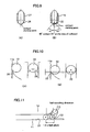
- FIGs. 9 and 10 illustrates a state of contact between the ball 13 and the scoop section 22, at the tip of the scoop section 22, for comparison between the conventional scoop section 28 and the scoop section 22 of the present embodiment.
- Fig. 9 illustrates the end plates ((A) indicating the conventional end plate 27 and (B) indicating the end plate 15 according to the present embodiment).
- Fig. 10 illustrates the details of the scoop section 22 ((A) indicating the conventional scoop section 28 and (B) indicating the scoop section 22 according to the present embodiment).
- the ball 13 contacts a tip of the scoop section 28 at the contact starting position through one point, and the ball 13 also contacts the ball rolling groove 11a through one point.
- the ball 13 contacts the scoop section 22 at the contact starting position through two points, and the ball 13 also contacts the ball rolling groove 11a through one point.
- Such a structure of three-point contact can also mitigate damages on the scoop section 22 in high-speed movement. It will be appreciated that, since the arc surface is formed at the contact starting position, the contact angle ⁇ of the scoop section 22 at the contact starting position becomes smaller than 45°, for example, 41°.
- FIG. 11 illustrates an example of how to determine a distance from the end face of the moving block body 14 to the scoop section 22.
- Fig. 11 illustrates how to determine a maximum value of the distance
- Fig. 12 illustrates how to determine a minimum value of the distance.
- a ball A is considered to suffer resistance.
- a center of the ball A is positioned on the end face of the moving block body 14.
- the scoop section 22 is displaced backward, so that, even when a ball B pushing the ball A moves up and down and contacts the raceway rail, the scoop section 22 is not brought into contact with the ball 13.
- the maximum value of the distance from the end face of the moving block body 14 to the tip of the scoop section 22 results in about 1.5xball pitch.
- the moving block body 14 is provided with crowning.
- the ball A When the ball A has entered the load ball rolling path 23, the ball A is considered to suffer resistance.
- the end point of the ball A is positioned on the end face of the moving block body 14.
- the scoop section 22 is displaced backward, so that even when the ball B pushing the ball A moves up and down and contacts the raceway rail, the scoop section 22 is not brought into contact with the ball 13.
- the minimum value of the distance from the end face of the moving block body 14 to the tip of the scoop section 22 results in about 0.5xball pitch.
- the distance from the end face of the moving block body 14 to the tip of the scoop section 22 is determined to be from about 0.5 to about 1.5xball pitch.
- the distance from the end face of the moving block body 14 to the tip of the scoop section 22 is preferably determined to be from about 0.75 to about 1.25xball pitch.
- the present invention is not limited to the embodiment described above but may be modified in various ways within the scope of the claims.
- the present invention may be applied not only to a linear guide but also to a ball spline.
Landscapes
- Engineering & Computer Science (AREA)
- General Engineering & Computer Science (AREA)
- Mechanical Engineering (AREA)
- Bearings For Parts Moving Linearly (AREA)
Claims (3)
- Bewegungs-Leitvorrichtung, die umfasst:ein Laufbahnelement (11), in dem Kugel-Rollnuten (11a) ausgebildet sind; ein Bewegungselement (12), das mit Rollnuten (14a) für belastete Kugeln versehen ist, die den Kugel-Rollnuten (11a) zugewandt sind, und Rücklaufwege (17, 21) für lastfreie Kugeln aufweist, die jeweils ein Ende und das andere Ende der Rollnuten (14a) für belastete Kugeln verbinden; und eine Vielzahl von Kugeln (13), die in Rollwegen für belastete Kugeln, die jeweils zwischen der Kugel-Rollnut (11a) des Laufbahnelementes (11) und der Rollnut (14a) für belastete Kugeln des Bewegungselementes (12) ausgebildet sind, und in den Rücklaufwegen (17, 21) für lastfreie Kugeln angeordnet sind, wobei die Vorrichtung die in den Kugel-Rollnuten (11a) des Laufbahnelementes (11) rollenden Kugeln (13) mit Hilfe eines Anhebeabschnitts (22) des Bewegungselementes (12) zum Einleiten in die Rücklaufwege (17, 21) für lastfreie Kugeln anhebt,dadurch gekennzeichnet, dassder Anhebeabschnitt (22) in Form einer Spitzbogennut für Zweipunktkontakt mit der Kugel (13) ausgebildet ist; undin einem Querschnitt senkrecht zu einer Laufrichtung der Kugeln (13):ein Winkel (Kontaktwinkel α), der zwischen einer Linie (L1), die einen Punkt (P), an dem der Anhebeabschnitt (22) mit der Kugel (13) in Kontakt kommt, mit einem Mittelpunkt (C) der Kugel (13) verbindet, und einer Linie gebildet wird, die den Mittelpunkt (C) der Kugel (13) mit einem unteren Ende (22a) des Anhebeabschnitts (22) der Spitzbogennut verbindet, mehr als 30° beträgt und genauso groß ist wie oder kleiner als ein Winkel (γ), der zwischen einer Linie (L3), die den Mittelpunkt (C) der Kugel (13), die in den Kugel-Rollnuten (11a) des Laufbahnelementes (11) rollt, mit einer Kante (35) der Kugel-Rollnut (11a) in dem Laufbahnelement (11) verbindet, und der Linie (L2) ausgebildet ist, die den Mittelpunkt (C) der Kugel (13) mit einem Boden der Kugel-Rollnut (11a) in dem Laufbahnelement (11) verbindet,wobei in einem Querschnitt entlang der Laufrichtung der Kugeln (13) die Vorderkante (22b) des Anhebeabschnitts (22) in einer Form ausgebildet ist, als ob die Vorderkante (22b) abgeschnitten worden wäre, und Abschrägen durchgeführt wird, um eine Bogenfläche an der Kontakt-Anfangsposition zu schaffen, an der die Kugel (13) zuerst mit dem Anhebeabschnitt (22) in Kontakt kommt, wenn der Anhebeabschnitt (22) die Kugel (13) anhebt, die in der Kugel-Rollnut (11a) des Laufbahnelementes (11) rollt.
- Bewegungs-Leitvorrichtung nach Anspruch 1, dadurch gekennzeichnet, dass der Kontaktwinkel (α) 40° oder mehr und 60° oder weniger beträgt.
- Bewegungs-Leitvorrichtung nach einem der Ansprüche 1 oder 2, dadurch gekennzeichnet, dass das Bewegungselement (12) umfasst:einen Bewegungsblock-Körper (14), der mit den Rollnuten (14a) für belastete Kugeln und Kugeln-Austrittswegen (17) versehen ist, die jeweils parallel zu jeder der Rollnuten (14a) für belastete Kugeln mit einem vorgegebenen Abstand dazwischen verlaufen; undAbschlussplatten (15), die an beiden Enden des Bewegungsblock-Körpers (14) in seiner Laufrichtung vorhanden sind, und in denen jeweils ein äußerer Rand eines Richtungsänderungsweges (21), der Verbindung zwischen dem Kugel-Austrittsweg (17) und dem Rollweg (23) für belastete Kugeln herstellt, für Umlauf der Kugeln (13) ausgebildet ist,wobei der Anhebeabschnitt (22) an der Abschlussplatte (15) vorhanden ist.
Applications Claiming Priority (2)
| Application Number | Priority Date | Filing Date | Title |
|---|---|---|---|
| JP2004246524 | 2004-08-26 | ||
| EP05780936A EP1793135B1 (de) | 2004-08-26 | 2005-08-25 | Bewegungsführungsvorrichtung |
Related Parent Applications (1)
| Application Number | Title | Priority Date | Filing Date |
|---|---|---|---|
| EP05780936.0 Division | 2005-08-25 |
Publications (2)
| Publication Number | Publication Date |
|---|---|
| EP2287480A1 EP2287480A1 (de) | 2011-02-23 |
| EP2287480B1 true EP2287480B1 (de) | 2013-01-23 |
Family
ID=35967528
Family Applications (2)
| Application Number | Title | Priority Date | Filing Date |
|---|---|---|---|
| EP10013280A Expired - Lifetime EP2287480B1 (de) | 2004-08-26 | 2005-08-25 | Bewegungsführungsvorrichtung |
| EP05780936A Expired - Lifetime EP1793135B1 (de) | 2004-08-26 | 2005-08-25 | Bewegungsführungsvorrichtung |
Family Applications After (1)
| Application Number | Title | Priority Date | Filing Date |
|---|---|---|---|
| EP05780936A Expired - Lifetime EP1793135B1 (de) | 2004-08-26 | 2005-08-25 | Bewegungsführungsvorrichtung |
Country Status (8)
| Country | Link |
|---|---|
| US (1) | US7980763B2 (de) |
| EP (2) | EP2287480B1 (de) |
| JP (1) | JP4606416B2 (de) |
| KR (1) | KR101217377B1 (de) |
| CN (1) | CN100575727C (de) |
| DE (1) | DE602005024028D1 (de) |
| TW (1) | TWI346183B (de) |
| WO (1) | WO2006022321A1 (de) |
Families Citing this family (13)
| Publication number | Priority date | Publication date | Assignee | Title |
|---|---|---|---|---|
| CN101317017B (zh) | 2005-11-01 | 2010-06-30 | Thk株式会社 | 运动引导装置 |
| JP3964926B2 (ja) * | 2005-11-30 | 2007-08-22 | 株式会社 空スペース | 転がり装置、及びその製造方法 |
| CN101802424B (zh) * | 2007-09-14 | 2012-10-10 | Thk株式会社 | 导轨以及具备该导轨的运动引导装置 |
| JP2012101779A (ja) * | 2010-10-14 | 2012-05-31 | Jtekt Corp | ラック・ピニオン式ステアリング装置 |
| DE112012004607T5 (de) * | 2011-11-04 | 2014-08-28 | Thk Co., Ltd. | Bewegungs-Leitvorrichtung |
| JP2014202219A (ja) * | 2013-04-01 | 2014-10-27 | 日本精工株式会社 | リニアガイド装置 |
| JP2016020735A (ja) * | 2014-06-19 | 2016-02-04 | 日本精工株式会社 | リニアガイド装置 |
| JP5932926B2 (ja) * | 2014-09-19 | 2016-06-08 | Thk株式会社 | 運動案内装置、アクチュエータ |
| JP6668652B2 (ja) | 2015-09-18 | 2020-03-18 | 日本精工株式会社 | 直動案内装置、直動案内装置用エンドキャップ |
| JP6981746B2 (ja) * | 2016-10-26 | 2021-12-17 | 日本トムソン株式会社 | 直動案内ユニット |
| WO2019044493A1 (ja) | 2017-08-29 | 2019-03-07 | Thk株式会社 | 運動案内装置 |
| JP7219877B2 (ja) * | 2017-08-29 | 2023-02-09 | Thk株式会社 | 運動案内装置 |
| JP7725844B2 (ja) * | 2021-03-26 | 2025-08-20 | 日本精工株式会社 | リニアガイド |
Family Cites Families (11)
| Publication number | Priority date | Publication date | Assignee | Title |
|---|---|---|---|---|
| JPS61274118A (ja) | 1985-05-28 | 1986-12-04 | Hiroshi Teramachi | 直線摺動用ボ−ルベアリング |
| US4749284A (en) * | 1985-05-28 | 1988-06-07 | Hiroshi Teramachi | Linear sliding ball bearing |
| JP2697795B2 (ja) | 1988-09-26 | 1998-01-14 | 日本トムソン株式会社 | 小形直動案内ユニット |
| JP3231532B2 (ja) | 1994-01-24 | 2001-11-26 | テイエチケー株式会社 | 直線案内装置 |
| JP3426733B2 (ja) | 1994-10-14 | 2003-07-14 | Thk株式会社 | 直線案内装置 |
| JP3296716B2 (ja) * | 1996-05-02 | 2002-07-02 | テイエチケー株式会社 | 転がり運動案内装置および転がり運動案内装置の移動部材の製造方法 |
| US5897212A (en) * | 1996-08-30 | 1999-04-27 | Nsk Ltd. | Linear guide assembly |
| CN1126875C (zh) * | 1999-10-22 | 2003-11-05 | 卢兆平 | 半圆滚动轴承 |
| JP3420204B2 (ja) * | 2000-11-17 | 2003-06-23 | Thk株式会社 | 案内装置 |
| JP2004068880A (ja) | 2002-08-05 | 2004-03-04 | Nsk Ltd | 直動装置 |
| JP4244585B2 (ja) * | 2002-08-05 | 2009-03-25 | Nok株式会社 | 密封装置 |
-
2005
- 2005-08-25 CN CN200580028786A patent/CN100575727C/zh not_active Expired - Lifetime
- 2005-08-25 KR KR1020077006636A patent/KR101217377B1/ko not_active Expired - Lifetime
- 2005-08-25 WO PCT/JP2005/015412 patent/WO2006022321A1/ja not_active Ceased
- 2005-08-25 EP EP10013280A patent/EP2287480B1/de not_active Expired - Lifetime
- 2005-08-25 JP JP2006531970A patent/JP4606416B2/ja not_active Expired - Lifetime
- 2005-08-25 US US11/660,960 patent/US7980763B2/en active Active
- 2005-08-25 EP EP05780936A patent/EP1793135B1/de not_active Expired - Lifetime
- 2005-08-25 DE DE602005024028T patent/DE602005024028D1/de not_active Expired - Lifetime
- 2005-08-26 TW TW094129272A patent/TWI346183B/zh not_active IP Right Cessation
Also Published As
| Publication number | Publication date |
|---|---|
| EP1793135B1 (de) | 2010-10-06 |
| US7980763B2 (en) | 2011-07-19 |
| JP4606416B2 (ja) | 2011-01-05 |
| EP2287480A1 (de) | 2011-02-23 |
| TW200613657A (en) | 2006-05-01 |
| EP1793135A1 (de) | 2007-06-06 |
| CN100575727C (zh) | 2009-12-30 |
| KR101217377B1 (ko) | 2012-12-31 |
| US20080212905A1 (en) | 2008-09-04 |
| TWI346183B (en) | 2011-08-01 |
| DE602005024028D1 (de) | 2010-11-18 |
| JPWO2006022321A1 (ja) | 2008-05-08 |
| CN101014778A (zh) | 2007-08-08 |
| KR20070049674A (ko) | 2007-05-11 |
| WO2006022321A1 (ja) | 2006-03-02 |
| EP1793135A4 (de) | 2009-01-14 |
Similar Documents
| Publication | Publication Date | Title |
|---|---|---|
| EP1793135B1 (de) | Bewegungsführungsvorrichtung | |
| US7771119B2 (en) | Linear guide apparatus | |
| CN106133350B (zh) | 直线运动引导装置 | |
| CN101484712B (zh) | 直线引导装置 | |
| US20080124010A1 (en) | Spacer | |
| US6238313B1 (en) | Drive belt | |
| JP4051845B2 (ja) | 直動案内軸受装置 | |
| US5391003A (en) | Rolling guide unit | |
| CN103097752A (zh) | 直线运动装置 | |
| EP1326026A1 (de) | Linearführungseinheit mit Trennkörpern zwischen jedem angrenzendem Wälzkörper | |
| US11852192B2 (en) | Motion guide apparatus | |
| CN103782047A (zh) | 运动引导装置 | |
| US7121723B2 (en) | Linear guide apparatus | |
| JPS61274117A (ja) | 直線案内ベアリングのボ−ル保持器 | |
| JP4192479B2 (ja) | 直動装置 | |
| JP7221814B2 (ja) | 運動案内装置 | |
| EP1953399A1 (de) | Bewegungsführungsvorrichtung | |
| US20230184291A1 (en) | Motion guide apparatus | |
| JP2024150228A (ja) | 直動案内装置 | |
| WO2005038276A1 (ja) | リニアガイド装置 | |
| US7578620B2 (en) | Linear guide device | |
| JP2001214932A (ja) | 直線運動装置 | |
| JP2026060266A (ja) | 直動案内装置 | |
| JP2579090Y2 (ja) | 直動形ガイド装置 | |
| JPH0652085B2 (ja) | 直線摺動用ベアリング |
Legal Events
| Date | Code | Title | Description |
|---|---|---|---|
| PUAI | Public reference made under article 153(3) epc to a published international application that has entered the european phase |
Free format text: ORIGINAL CODE: 0009012 |
|
| AC | Divisional application: reference to earlier application |
Ref document number: 1793135 Country of ref document: EP Kind code of ref document: P |
|
| AK | Designated contracting states |
Kind code of ref document: A1 Designated state(s): DE FR IT |
|
| 17P | Request for examination filed |
Effective date: 20110818 |
|
| GRAP | Despatch of communication of intention to grant a patent |
Free format text: ORIGINAL CODE: EPIDOSNIGR1 |
|
| GRAS | Grant fee paid |
Free format text: ORIGINAL CODE: EPIDOSNIGR3 |
|
| GRAA | (expected) grant |
Free format text: ORIGINAL CODE: 0009210 |
|
| AC | Divisional application: reference to earlier application |
Ref document number: 1793135 Country of ref document: EP Kind code of ref document: P |
|
| AK | Designated contracting states |
Kind code of ref document: B1 Designated state(s): DE FR IT |
|
| REG | Reference to a national code |
Ref country code: DE Ref legal event code: R096 Ref document number: 602005038031 Country of ref document: DE Effective date: 20130321 |
|
| PLBE | No opposition filed within time limit |
Free format text: ORIGINAL CODE: 0009261 |
|
| STAA | Information on the status of an ep patent application or granted ep patent |
Free format text: STATUS: NO OPPOSITION FILED WITHIN TIME LIMIT |
|
| 26N | No opposition filed |
Effective date: 20131024 |
|
| REG | Reference to a national code |
Ref country code: DE Ref legal event code: R097 Ref document number: 602005038031 Country of ref document: DE Effective date: 20131024 |
|
| REG | Reference to a national code |
Ref country code: FR Ref legal event code: PLFP Year of fee payment: 12 |
|
| REG | Reference to a national code |
Ref country code: FR Ref legal event code: PLFP Year of fee payment: 13 |
|
| REG | Reference to a national code |
Ref country code: FR Ref legal event code: PLFP Year of fee payment: 14 |
|
| P01 | Opt-out of the competence of the unified patent court (upc) registered |
Effective date: 20230920 |
|
| PGFP | Annual fee paid to national office [announced via postgrant information from national office to epo] |
Ref country code: DE Payment date: 20240821 Year of fee payment: 20 |
|
| PGFP | Annual fee paid to national office [announced via postgrant information from national office to epo] |
Ref country code: FR Payment date: 20240828 Year of fee payment: 20 |
|
| PGFP | Annual fee paid to national office [announced via postgrant information from national office to epo] |
Ref country code: IT Payment date: 20240827 Year of fee payment: 20 |
|
| REG | Reference to a national code |
Ref country code: DE Ref legal event code: R071 Ref document number: 602005038031 Country of ref document: DE |