EP2287531B1 - Dispositif de mélange de combustible et d'air pour un système de combustion - Google Patents
Dispositif de mélange de combustible et d'air pour un système de combustion Download PDFInfo
- Publication number
- EP2287531B1 EP2287531B1 EP10171713.0A EP10171713A EP2287531B1 EP 2287531 B1 EP2287531 B1 EP 2287531B1 EP 10171713 A EP10171713 A EP 10171713A EP 2287531 B1 EP2287531 B1 EP 2287531B1
- Authority
- EP
- European Patent Office
- Prior art keywords
- pressure
- gas
- combustion gas
- control valve
- stage
- Prior art date
- Legal status (The legal status is an assumption and is not a legal conclusion. Google has not performed a legal analysis and makes no representation as to the accuracy of the status listed.)
- Active
Links
Images
Classifications
-
- F—MECHANICAL ENGINEERING; LIGHTING; HEATING; WEAPONS; BLASTING
- F23—COMBUSTION APPARATUS; COMBUSTION PROCESSES
- F23D—BURNERS
- F23D14/00—Burners for combustion of a gas, e.g. of a gas stored under pressure as a liquid
- F23D14/46—Details
- F23D14/60—Devices for simultaneous control of gas and combustion air
-
- F—MECHANICAL ENGINEERING; LIGHTING; HEATING; WEAPONS; BLASTING
- F23—COMBUSTION APPARATUS; COMBUSTION PROCESSES
- F23N—REGULATING OR CONTROLLING COMBUSTION
- F23N1/00—Regulating fuel supply
- F23N1/02—Regulating fuel supply conjointly with air supply
- F23N1/022—Regulating fuel supply conjointly with air supply using electronic means
-
- F—MECHANICAL ENGINEERING; LIGHTING; HEATING; WEAPONS; BLASTING
- F23—COMBUSTION APPARATUS; COMBUSTION PROCESSES
- F23N—REGULATING OR CONTROLLING COMBUSTION
- F23N5/00—Systems for controlling combustion
- F23N5/18—Systems for controlling combustion using detectors sensitive to rate of flow of air or fuel
- F23N5/184—Systems for controlling combustion using detectors sensitive to rate of flow of air or fuel using electronic means
-
- F—MECHANICAL ENGINEERING; LIGHTING; HEATING; WEAPONS; BLASTING
- F23—COMBUSTION APPARATUS; COMBUSTION PROCESSES
- F23K—FEEDING FUEL TO COMBUSTION APPARATUS
- F23K2400/00—Pretreatment and supply of gaseous fuel
- F23K2400/20—Supply line arrangements
- F23K2400/201—Control devices
-
- F—MECHANICAL ENGINEERING; LIGHTING; HEATING; WEAPONS; BLASTING
- F23—COMBUSTION APPARATUS; COMBUSTION PROCESSES
- F23K—FEEDING FUEL TO COMBUSTION APPARATUS
- F23K2900/00—Special features of, or arrangements for fuel supplies
- F23K2900/05001—Control or safety devices in gaseous or liquid fuel supply lines
-
- F—MECHANICAL ENGINEERING; LIGHTING; HEATING; WEAPONS; BLASTING
- F23—COMBUSTION APPARATUS; COMBUSTION PROCESSES
- F23N—REGULATING OR CONTROLLING COMBUSTION
- F23N2225/00—Measuring
- F23N2225/04—Measuring pressure
- F23N2225/06—Measuring pressure for determining flow
-
- F—MECHANICAL ENGINEERING; LIGHTING; HEATING; WEAPONS; BLASTING
- F23—COMBUSTION APPARATUS; COMBUSTION PROCESSES
- F23N—REGULATING OR CONTROLLING COMBUSTION
- F23N2235/00—Valves, nozzles or pumps
- F23N2235/12—Fuel valves
- F23N2235/16—Fuel valves variable flow or proportional valves
-
- F—MECHANICAL ENGINEERING; LIGHTING; HEATING; WEAPONS; BLASTING
- F23—COMBUSTION APPARATUS; COMBUSTION PROCESSES
- F23N—REGULATING OR CONTROLLING COMBUSTION
- F23N2235/00—Valves, nozzles or pumps
- F23N2235/12—Fuel valves
- F23N2235/18—Groups of two or more valves
Definitions
- the invention relates to a method for setting an outlet pressure of a fuel gas volume flow at an outlet of a gas valve for a combustion system, in particular for a gas burner, according to the preamble of claim 1.
- a method for setting an outlet pressure of a fuel gas volume flow at an outlet of a gas valve for a combustion system, in particular for a gas burner according to the preamble of claim 1.
- Such a method is known from the US2009 / 092936 known.
- the invention further relates to a device for setting an outlet pressure of a fuel gas volume flow at an outlet of a gas valve for a combustion system, in particular for a gas burner, according to claim 4.
- the invention also relates to a fuel gas / air mixing device, in particular a fuel gas / air mixing device for generating and supplying a fuel gas / air mixture for a combustion system, in particular for a gas burner.
- the invention relates to a combustion system, in particular a combustion system with a gas burner, according to claim 7.
- Combustion systems fuel gas-air mixing devices and methods and devices for setting an output pressure of a fuel gas volume flow at an outlet of a gas valve for a combustion system, in particular for a gas burner, are generally known from the prior art.
- a fuel gas-air mixture is completely produced upstream of a pneumatic circuit, which has a gas valve, to a blower.
- the gas valve ensures that a gas pressure always corresponds to a reference pressure.
- the gas premixing valve has a control membrane. There is a reference pressure on one side of the membrane. There is an outlet pressure on the other side. The pressures on the sides are similar, so that only slight forces act on the membrane. As a result, the membrane is potentially unstable. Due to the instability, the premix gas valve has a low flow restriction. In addition, the valve construction is very sensitive.
- the invention has for its object to provide a device and a method for setting an output pressure of a fuel gas volume flow at an outlet of a gas valve for a combustion system, which are less sensitive and more stable over a larger gas flow range.
- the invention is also based on the object of providing a fuel gas-air mixing device, in particular a fuel gas-air mixing device for generating and supplying a fuel gas-air mixture for a combustion system and a combustion system, in particular a combustion system with a gas burner, with a device according to the invention to create, which realize an effective way of working with reduced total effort, and which work stable and insensitive even with larger flows.
- a fuel gas-air mixing device in particular a fuel gas-air mixing device for generating and supplying a fuel gas-air mixture for a combustion system and a combustion system, in particular a combustion system with a gas burner
- the two-stage zero pressure control valve for gas burners which are operated with a premixed fuel gas / air mixture, divides the pressure control into two stages.
- the inlet pressure is changed via a servo pressure regulator from an inlet pressure to a pressure that corresponds to the reference pressure plus a pressure component.
- a pressure drop valve reduces this pressure by the amount of pressure, whereby pressure is obtained at the output of the reference.
- a safety valve function can be realized in each stage, thereby avoiding the use of two additional valves in order to obtain the prescribed safety redundancy.
- the design according to the invention realizes a stable valve which is also insensitive to robust use.
- the valve is also suitable for larger flows and can be easily adjusted. Due to the pressure difference on the membrane on both sides, the higher stability is guaranteed.
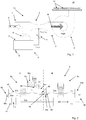
- Fig. 1 shows schematically a fuel gas-air mixing device 10.
- the fuel gas-air mixing device 10 comprises two feed lines 1, 2, which open into a common feed line 3.
- the first supply line 1 is designed for supplying air A.
- the second supply line 2 is designed for supplying a fuel gas B.
- a device 4 for setting an outlet pressure Pout of a fuel gas volume flow is provided in the second feed line 2.
- the device 4 comprises a two-stage control valve 5, which in Fig. 2 is described in more detail.
- the device 4, more precisely the control valve 5, is fluidly connected to the first supply line 1 via a pressure line 6, so that a reference pressure of the air supply serving as reference pressure Pref is applied to the control valve 5.
- the outlet pressure of the gas Pout is present at an outlet of the control valve 5.
- the control valve 4 is designed so that the gas outlet pressure Pout corresponds to the reference pressure Pref. Downstream of the control valve 5, a controller 7 is provided for setting a gas pressure for the mouth area in the common feed line 3.
- the feed lines including the mouth area of the feed lines 1, 2 are in the embodiment according to Fig. 1 formed as a Venturi tube 8.
- the fuel gas-air mixture M mixed from fuel gas B and air A continues to flow via a feed device 9, which in the exemplary embodiment according to FIG Figure 1 includes a blower. From the blower, the fuel gas-air mixture M is passed into a burner chamber 11 of a gas burner, where, as represented by the plurality of flames 12, it is used for combustion.
- Fig. 2 shows schematically an embodiment of a device 4 with a two-stage control valve 5.
- the fuel gas B flows into an inlet 51 of the control valve 5 with an inlet pressure Pi into a first control valve section 50a.
- the first control valve section 50a is delimited to an adjacent control valve section 50b by a membrane 52, on which the inlet pressure Pi is consequently present on one side of the membrane 52.
- the membrane 52 is additionally loaded with a pressure Pc of a compression spring acting on the membrane 52.
- a third control valve section 50c which is delimited by a membrane 53 from the second control valve section 50b, there is a reference pressure Pref which can be set by means of a further pressure spring.
- the first control valve section 50a is connected to the second control valve section 50b via a first fuel gas line 55a, which has a control element 56 for setting a gas flow.
- the diaphragms 52 and 53 are each prestressed by means of a compression spring or additionally subjected to pressure.
- the reference pressure Pref is present, increased by a pressure component Px.
- the second control valve section 50b is connected to the fourth control valve section 20d via a further, second fuel gas line 55b.
- a control element 56 is also provided in the second fuel gas line 55b.
- first pressure stage I of the control valve 50 This is followed by a second pressure stage II, in which the reference pressure Pref increased by the pressure component Px is constantly reduced to the reference pressure Pref.
- the fourth control valve section 50d is delimited via a further membrane 58 to a fifth control valve section 50e.
- the fourth control valve section 50d is connected to the fifth control valve section 50e via a third fuel gas line 55c, which also has a control element 56.
- the membrane 58 is adjustable Spring preloaded or pressurized. In the fifth control valve section 50e, constant pressure throttling is brought about via the spring preload.
- the membrane 58 separates the fifth control valve section 50e from a sixth control valve section 50f.
- the sixth control valve section 50f is connected to the fifth control valve section 50e via a fourth fuel gas line 55d.
- the fourth fuel gas line 55d likewise comprises a control element 56 for flow control, in particular a binary flow control element.
- the components constantly reduce the pressure to an outlet pressure Pout, which corresponds to the reference pressure Pref.
Landscapes
- Engineering & Computer Science (AREA)
- Chemical & Material Sciences (AREA)
- Combustion & Propulsion (AREA)
- Mechanical Engineering (AREA)
- General Engineering & Computer Science (AREA)
- Feeding And Controlling Fuel (AREA)
- Regulation And Control Of Combustion (AREA)
Claims (7)
- Procédé de réglage d'une pression de sortie (Pout) d'un débit volumique de gaz combustible à la sortie d'une soupape à gaz destinée à un système de combustion (10), en particulier à un brûleur à gaz, dans lequel de l'air (A) et un gaz combustible (B) sont préalablement mélangés et la pression de sortie (Pout) du gaz combustible (B) est réglée à une pression de référence (Pref) avant d'entrer dans une chambre de mélange, la pression de sortie (Pout) du gaz combustible (B) étant réglée dans deux étages et, dans une premier étage (I), une pression (Pi) régnant du côté entrée étant réduite, caractérisé en ce que la pression (Pi) régnant du côté entrée dans le premier étage (I) est réduite à la pression de référence (Pref) plus une composante de pression prédéterminée (Px).
- Procédé selon la revendication 1,
caractérisé en ce que, dans une deuxième étape (II), la pression réduite est encore réduite de la composante de pression prédéterminée (Px) jusqu'à la pression de référence (Pref). - Procédé selon l'une des revendications 1 et 2 précédentes, caractérisé en ce que la pression dans le deuxième étage (II) est réduite constamment de la composante de pression (Px) jusqu'à la pression de référence (Pref).
- Dispositif (4) de réglage d'une pression de sortie (Pout) d'un débit volumique de gaz combustible à la sortie d'une soupape à gaz destinée à un système de combustion (10), en particulier à un brûleur à gaz, procédé dans lequel de l'air (A) et un gaz combustible (B) sont préalablement mélangés et la pression de sortie (Pout) du gaz combustible (B) est réglée à une pression de référence (Pref) avant d'entrer dans une chambre de mélange,
caractérisé en ce qu'il est prévu des moyens de mise en œuvre du procédé selon l'une des revendications 1 à 3, les moyens comprenant au moins une soupape de réglage à deux étages (5), en particulier une soupape de réglage à pression nulle à deux étages, destinée à régler sur deux étages la pression du mélange air-carburant (M) et en ce que la soupape de réglage sur deux étages (5) comporte, pour le premier étage (I), une unité de soupape de régulateur de pression asservie (5a) afin de réduire une pression (Pi) présente du côté entrée. - Dispositif (4) selon la revendication 4, caractérisé en ce que la soupape de réglage à deux étages (5) comprend, pour le deuxième étage (II), une unité de soupape à chute de pression (5b) pour provoquer une chute de pression, en particulier une chute de pression constante.
- Dispositif de mélange gaz combustible/air (10), en particulier dispositif de mélange gaz combustible/air (10) destiné à générer et alimenter un système de combustion, en particulier un brûleur à gaz, avec un mélange gaz combustible/air (M), système dans lequel de l'air (A) et un gaz combustible (B) sont préalablement mélangés et la pression (Pout) d'un débit volumique de gaz combustible est fixée à une pression de référence (Pref) avant d'entrer dans une chambre de mélange, caractérisé en ce qu'au moins un dispositif (4) selon l'une des revendications 4 et 5 est inclus.
- Système de combustion (10), en particulier système de combustion (10) comprenant un brûleur à gaz, dans lequel de l'air (A) et un gaz combustible (B) sont préalablement mélangés et la pression (Pout) d'un débit volumique de gaz combustible est réglée à une pression de référence (Pref) avant d'entrer dans une chambre de mélange,
caractérisé en ce qu'au moins un dispositif de mélange gaz combustible/air (10) selon la revendication 6 est inclus.
Applications Claiming Priority (1)
| Application Number | Priority Date | Filing Date | Title |
|---|---|---|---|
| DE102009037890A DE102009037890B4 (de) | 2009-08-18 | 2009-08-18 | Vorrichtung zum Einstellen eines Ausgangsdrucks eines Brenngasvolumenstromes, Verfahren zum Einstellen eines Ausgangsdrucks sowie Verwendung der Vorrichtung in einer Brenngas-Luft-Mischeinrichtung für ein Verbrennungssystem |
Publications (3)
| Publication Number | Publication Date |
|---|---|
| EP2287531A2 EP2287531A2 (fr) | 2011-02-23 |
| EP2287531A3 EP2287531A3 (fr) | 2014-12-31 |
| EP2287531B1 true EP2287531B1 (fr) | 2020-02-19 |
Family
ID=43067036
Family Applications (1)
| Application Number | Title | Priority Date | Filing Date |
|---|---|---|---|
| EP10171713.0A Active EP2287531B1 (fr) | 2009-08-18 | 2010-08-03 | Dispositif de mélange de combustible et d'air pour un système de combustion |
Country Status (2)
| Country | Link |
|---|---|
| EP (1) | EP2287531B1 (fr) |
| DE (1) | DE102009037890B4 (fr) |
Families Citing this family (2)
| Publication number | Priority date | Publication date | Assignee | Title |
|---|---|---|---|---|
| US9273638B2 (en) * | 2013-04-15 | 2016-03-01 | Ford Global Technologies, Llc | Variable pressure gaseous fuel regulator |
| DE102020121597A1 (de) | 2020-08-18 | 2022-02-24 | Vaillant Gmbh | Verfahren und Anordnung zur pneumatischen Gemischbildung bei einem Vormischbrenner |
Family Cites Families (5)
| Publication number | Priority date | Publication date | Assignee | Title |
|---|---|---|---|---|
| US4251025A (en) * | 1979-07-12 | 1981-02-17 | Honeywell Inc. | Furnace control using induced draft blower and exhaust stack flow rate sensing |
| DE9316918U1 (de) * | 1993-11-05 | 1994-01-13 | Karl Dungs GmbH & Co, 73660 Urbach | Mehrfachstellgerät mit eingangsseitigem Regler |
| DE19722600C2 (de) * | 1997-05-30 | 2002-06-27 | Dungs Karl Gmbh & Co | Servoregler |
| DE29808799U1 (de) * | 1998-05-15 | 1999-09-16 | Honeywell B.V., Amsterdam | Regeleinrichtung für Gasbrenner |
| US7789657B2 (en) * | 2007-10-03 | 2010-09-07 | Honeywell International Inc. | Pressure regulator with bleed orifice |
-
2009
- 2009-08-18 DE DE102009037890A patent/DE102009037890B4/de not_active Expired - Fee Related
-
2010
- 2010-08-03 EP EP10171713.0A patent/EP2287531B1/fr active Active
Non-Patent Citations (1)
| Title |
|---|
| None * |
Also Published As
| Publication number | Publication date |
|---|---|
| DE102009037890A1 (de) | 2011-02-24 |
| DE102009037890B4 (de) | 2013-07-18 |
| EP2287531A2 (fr) | 2011-02-23 |
| EP2287531A3 (fr) | 2014-12-31 |
Similar Documents
| Publication | Publication Date | Title |
|---|---|---|
| DE19740666C1 (de) | Regelvorrichtung für das Einhalten eines geforderten Gas-/Luft-Verhältnisses für Gasbrenner | |
| DE19722600C2 (de) | Servoregler | |
| EP1730449B1 (fr) | Chambre de combustion pour turbine a gaz et procede de fonctionnement correspondant | |
| DE102006031875A1 (de) | Verfahren zum Öffnen von Tankabsperrventilen in Gaszufuhrsystemen mit verbundenen Tanks | |
| EP3957910B1 (fr) | Procédé et agencement de formation pneumatique d'un mélange dans un brûleur de prémélange | |
| EP1840465A2 (fr) | Système comportant des brûleurs à injection de carburant étagée | |
| EP1036984B3 (fr) | Brûleur à prémélange pour combustibles gazeux | |
| EP1959194B1 (fr) | Dispositif de mélange pour un brûleur à gaz comprenant un ventilateur | |
| EP2071156A1 (fr) | Système de distribution de carburant d'une turbine à gaz avec ensemble brûleur à plusieurs étages | |
| EP2866115A2 (fr) | Vanne dotée d'une cartouche échangeable | |
| DE102009037890B4 (de) | Vorrichtung zum Einstellen eines Ausgangsdrucks eines Brenngasvolumenstromes, Verfahren zum Einstellen eines Ausgangsdrucks sowie Verwendung der Vorrichtung in einer Brenngas-Luft-Mischeinrichtung für ein Verbrennungssystem | |
| EP2177830A1 (fr) | Brûleur à gaz pour une régulation combinée gaz-air | |
| DE102011056521A1 (de) | Ventilvorrichtung | |
| DE4038445C2 (de) | Gasarmatur | |
| EP1635066B1 (fr) | Installation d'alimentation en gaz et procédé d'utilisation associé pour une turbine à gaz | |
| DE10018757A1 (de) | Gasarmatur zum Regeln des Druckes und zum Absperren eines Gasstromes | |
| DE19821292A1 (de) | Zweistufiger Gasdruckregler | |
| DE3318896A1 (de) | Gasdruckregler | |
| DE2305764C3 (de) | Gasgemischdosiervorrichtung für einen mit Druckluft, Brenngas und Sauerstoff betriebenen Brenner | |
| DE19756301B4 (de) | Einrichtung zur Aufbereitung eines Gas-Luftgemisches | |
| DE2014162B2 (de) | Brennstoffregel vorrichtung für Gasturbinenstrahltriebwerke | |
| DE69711396T2 (de) | Durchflusssteuerungssystem | |
| EP1869348B1 (fr) | Systeme d'etancheite pour assurer l'etancheite d'un espace a gaz de procede vis-a-vis d'un espace etanche | |
| DE498427C (de) | Membrangasdruckregler | |
| DE1650320A1 (de) | Druckregel- und -begrenzungsventil |
Legal Events
| Date | Code | Title | Description |
|---|---|---|---|
| PUAI | Public reference made under article 153(3) epc to a published international application that has entered the european phase |
Free format text: ORIGINAL CODE: 0009012 |
|
| AK | Designated contracting states |
Kind code of ref document: A2 Designated state(s): AL AT BE BG CH CY CZ DE DK EE ES FI FR GB GR HR HU IE IS IT LI LT LU LV MC MK MT NL NO PL PT RO SE SI SK SM TR |
|
| AX | Request for extension of the european patent |
Extension state: BA ME RS |
|
| PUAL | Search report despatched |
Free format text: ORIGINAL CODE: 0009013 |
|
| AK | Designated contracting states |
Kind code of ref document: A3 Designated state(s): AL AT BE BG CH CY CZ DE DK EE ES FI FR GB GR HR HU IE IS IT LI LT LU LV MC MK MT NL NO PL PT RO SE SI SK SM TR |
|
| AX | Request for extension of the european patent |
Extension state: BA ME RS |
|
| RIC1 | Information provided on ipc code assigned before grant |
Ipc: F23N 1/02 20060101ALI20141121BHEP Ipc: F23D 14/60 20060101AFI20141121BHEP Ipc: F23N 5/18 20060101ALI20141121BHEP |
|
| 17P | Request for examination filed |
Effective date: 20150630 |
|
| RBV | Designated contracting states (corrected) |
Designated state(s): AL AT BE BG CH CY CZ DE DK EE ES FI FR GB GR HR HU IE IS IT LI LT LU LV MC MK MT NL NO PL PT RO SE SI SK SM TR |
|
| STAA | Information on the status of an ep patent application or granted ep patent |
Free format text: STATUS: EXAMINATION IS IN PROGRESS |
|
| 17Q | First examination report despatched |
Effective date: 20180509 |
|
| GRAP | Despatch of communication of intention to grant a patent |
Free format text: ORIGINAL CODE: EPIDOSNIGR1 |
|
| STAA | Information on the status of an ep patent application or granted ep patent |
Free format text: STATUS: GRANT OF PATENT IS INTENDED |
|
| INTG | Intention to grant announced |
Effective date: 20191112 |
|
| RIN1 | Information on inventor provided before grant (corrected) |
Inventor name: GUERREIRO, JOAO |
|
| GRAS | Grant fee paid |
Free format text: ORIGINAL CODE: EPIDOSNIGR3 |
|
| GRAA | (expected) grant |
Free format text: ORIGINAL CODE: 0009210 |
|
| STAA | Information on the status of an ep patent application or granted ep patent |
Free format text: STATUS: THE PATENT HAS BEEN GRANTED |
|
| AK | Designated contracting states |
Kind code of ref document: B1 Designated state(s): AL AT BE BG CH CY CZ DE DK EE ES FI FR GB GR HR HU IE IS IT LI LT LU LV MC MK MT NL NO PL PT RO SE SI SK SM TR |
|
| REG | Reference to a national code |
Ref country code: GB Ref legal event code: FG4D Free format text: NOT ENGLISH |
|
| REG | Reference to a national code |
Ref country code: CH Ref legal event code: EP |
|
| REG | Reference to a national code |
Ref country code: DE Ref legal event code: R096 Ref document number: 502010016490 Country of ref document: DE |
|
| REG | Reference to a national code |
Ref country code: AT Ref legal event code: REF Ref document number: 1235395 Country of ref document: AT Kind code of ref document: T Effective date: 20200315 |
|
| REG | Reference to a national code |
Ref country code: IE Ref legal event code: FG4D Free format text: LANGUAGE OF EP DOCUMENT: GERMAN |
|
| RAP2 | Party data changed (patent owner data changed or rights of a patent transferred) |
Owner name: ROBERT BOSCH GMBH |
|
| REG | Reference to a national code |
Ref country code: NL Ref legal event code: MP Effective date: 20200219 |
|
| PG25 | Lapsed in a contracting state [announced via postgrant information from national office to epo] |
Ref country code: NO Free format text: LAPSE BECAUSE OF FAILURE TO SUBMIT A TRANSLATION OF THE DESCRIPTION OR TO PAY THE FEE WITHIN THE PRESCRIBED TIME-LIMIT Effective date: 20200519 Ref country code: FI Free format text: LAPSE BECAUSE OF FAILURE TO SUBMIT A TRANSLATION OF THE DESCRIPTION OR TO PAY THE FEE WITHIN THE PRESCRIBED TIME-LIMIT Effective date: 20200219 |
|
| REG | Reference to a national code |
Ref country code: LT Ref legal event code: MG4D |
|
| PG25 | Lapsed in a contracting state [announced via postgrant information from national office to epo] |
Ref country code: IS Free format text: LAPSE BECAUSE OF FAILURE TO SUBMIT A TRANSLATION OF THE DESCRIPTION OR TO PAY THE FEE WITHIN THE PRESCRIBED TIME-LIMIT Effective date: 20200619 Ref country code: GR Free format text: LAPSE BECAUSE OF FAILURE TO SUBMIT A TRANSLATION OF THE DESCRIPTION OR TO PAY THE FEE WITHIN THE PRESCRIBED TIME-LIMIT Effective date: 20200520 Ref country code: HR Free format text: LAPSE BECAUSE OF FAILURE TO SUBMIT A TRANSLATION OF THE DESCRIPTION OR TO PAY THE FEE WITHIN THE PRESCRIBED TIME-LIMIT Effective date: 20200219 Ref country code: BG Free format text: LAPSE BECAUSE OF FAILURE TO SUBMIT A TRANSLATION OF THE DESCRIPTION OR TO PAY THE FEE WITHIN THE PRESCRIBED TIME-LIMIT Effective date: 20200519 Ref country code: LV Free format text: LAPSE BECAUSE OF FAILURE TO SUBMIT A TRANSLATION OF THE DESCRIPTION OR TO PAY THE FEE WITHIN THE PRESCRIBED TIME-LIMIT Effective date: 20200219 Ref country code: SE Free format text: LAPSE BECAUSE OF FAILURE TO SUBMIT A TRANSLATION OF THE DESCRIPTION OR TO PAY THE FEE WITHIN THE PRESCRIBED TIME-LIMIT Effective date: 20200219 |
|
| PG25 | Lapsed in a contracting state [announced via postgrant information from national office to epo] |
Ref country code: NL Free format text: LAPSE BECAUSE OF FAILURE TO SUBMIT A TRANSLATION OF THE DESCRIPTION OR TO PAY THE FEE WITHIN THE PRESCRIBED TIME-LIMIT Effective date: 20200219 |
|
| PG25 | Lapsed in a contracting state [announced via postgrant information from national office to epo] |
Ref country code: DK Free format text: LAPSE BECAUSE OF FAILURE TO SUBMIT A TRANSLATION OF THE DESCRIPTION OR TO PAY THE FEE WITHIN THE PRESCRIBED TIME-LIMIT Effective date: 20200219 Ref country code: LT Free format text: LAPSE BECAUSE OF FAILURE TO SUBMIT A TRANSLATION OF THE DESCRIPTION OR TO PAY THE FEE WITHIN THE PRESCRIBED TIME-LIMIT Effective date: 20200219 Ref country code: ES Free format text: LAPSE BECAUSE OF FAILURE TO SUBMIT A TRANSLATION OF THE DESCRIPTION OR TO PAY THE FEE WITHIN THE PRESCRIBED TIME-LIMIT Effective date: 20200219 Ref country code: SM Free format text: LAPSE BECAUSE OF FAILURE TO SUBMIT A TRANSLATION OF THE DESCRIPTION OR TO PAY THE FEE WITHIN THE PRESCRIBED TIME-LIMIT Effective date: 20200219 Ref country code: EE Free format text: LAPSE BECAUSE OF FAILURE TO SUBMIT A TRANSLATION OF THE DESCRIPTION OR TO PAY THE FEE WITHIN THE PRESCRIBED TIME-LIMIT Effective date: 20200219 Ref country code: CZ Free format text: LAPSE BECAUSE OF FAILURE TO SUBMIT A TRANSLATION OF THE DESCRIPTION OR TO PAY THE FEE WITHIN THE PRESCRIBED TIME-LIMIT Effective date: 20200219 Ref country code: RO Free format text: LAPSE BECAUSE OF FAILURE TO SUBMIT A TRANSLATION OF THE DESCRIPTION OR TO PAY THE FEE WITHIN THE PRESCRIBED TIME-LIMIT Effective date: 20200219 Ref country code: PT Free format text: LAPSE BECAUSE OF FAILURE TO SUBMIT A TRANSLATION OF THE DESCRIPTION OR TO PAY THE FEE WITHIN THE PRESCRIBED TIME-LIMIT Effective date: 20200712 Ref country code: SK Free format text: LAPSE BECAUSE OF FAILURE TO SUBMIT A TRANSLATION OF THE DESCRIPTION OR TO PAY THE FEE WITHIN THE PRESCRIBED TIME-LIMIT Effective date: 20200219 |
|
| REG | Reference to a national code |
Ref country code: DE Ref legal event code: R097 Ref document number: 502010016490 Country of ref document: DE |
|
| PLBE | No opposition filed within time limit |
Free format text: ORIGINAL CODE: 0009261 |
|
| STAA | Information on the status of an ep patent application or granted ep patent |
Free format text: STATUS: NO OPPOSITION FILED WITHIN TIME LIMIT |
|
| 26N | No opposition filed |
Effective date: 20201120 |
|
| PG25 | Lapsed in a contracting state [announced via postgrant information from national office to epo] |
Ref country code: IT Free format text: LAPSE BECAUSE OF FAILURE TO SUBMIT A TRANSLATION OF THE DESCRIPTION OR TO PAY THE FEE WITHIN THE PRESCRIBED TIME-LIMIT Effective date: 20200219 |
|
| PG25 | Lapsed in a contracting state [announced via postgrant information from national office to epo] |
Ref country code: PL Free format text: LAPSE BECAUSE OF FAILURE TO SUBMIT A TRANSLATION OF THE DESCRIPTION OR TO PAY THE FEE WITHIN THE PRESCRIBED TIME-LIMIT Effective date: 20200219 Ref country code: SI Free format text: LAPSE BECAUSE OF FAILURE TO SUBMIT A TRANSLATION OF THE DESCRIPTION OR TO PAY THE FEE WITHIN THE PRESCRIBED TIME-LIMIT Effective date: 20200219 |
|
| REG | Reference to a national code |
Ref country code: DE Ref legal event code: R119 Ref document number: 502010016490 Country of ref document: DE |
|
| PG25 | Lapsed in a contracting state [announced via postgrant information from national office to epo] |
Ref country code: MC Free format text: LAPSE BECAUSE OF FAILURE TO SUBMIT A TRANSLATION OF THE DESCRIPTION OR TO PAY THE FEE WITHIN THE PRESCRIBED TIME-LIMIT Effective date: 20200219 |
|
| REG | Reference to a national code |
Ref country code: CH Ref legal event code: PL |
|
| GBPC | Gb: european patent ceased through non-payment of renewal fee |
Effective date: 20200803 |
|
| PG25 | Lapsed in a contracting state [announced via postgrant information from national office to epo] |
Ref country code: LI Free format text: LAPSE BECAUSE OF NON-PAYMENT OF DUE FEES Effective date: 20200831 Ref country code: CH Free format text: LAPSE BECAUSE OF NON-PAYMENT OF DUE FEES Effective date: 20200831 Ref country code: LU Free format text: LAPSE BECAUSE OF NON-PAYMENT OF DUE FEES Effective date: 20200803 |
|
| REG | Reference to a national code |
Ref country code: BE Ref legal event code: MM Effective date: 20200831 |
|
| PG25 | Lapsed in a contracting state [announced via postgrant information from national office to epo] |
Ref country code: DE Free format text: LAPSE BECAUSE OF NON-PAYMENT OF DUE FEES Effective date: 20210302 Ref country code: FR Free format text: LAPSE BECAUSE OF NON-PAYMENT OF DUE FEES Effective date: 20200831 |
|
| PG25 | Lapsed in a contracting state [announced via postgrant information from national office to epo] |
Ref country code: BE Free format text: LAPSE BECAUSE OF NON-PAYMENT OF DUE FEES Effective date: 20200831 Ref country code: GB Free format text: LAPSE BECAUSE OF NON-PAYMENT OF DUE FEES Effective date: 20200803 Ref country code: IE Free format text: LAPSE BECAUSE OF NON-PAYMENT OF DUE FEES Effective date: 20200803 |
|
| REG | Reference to a national code |
Ref country code: AT Ref legal event code: MM01 Ref document number: 1235395 Country of ref document: AT Kind code of ref document: T Effective date: 20200803 |
|
| PG25 | Lapsed in a contracting state [announced via postgrant information from national office to epo] |
Ref country code: AT Free format text: LAPSE BECAUSE OF NON-PAYMENT OF DUE FEES Effective date: 20200803 |
|
| PG25 | Lapsed in a contracting state [announced via postgrant information from national office to epo] |
Ref country code: TR Free format text: LAPSE BECAUSE OF FAILURE TO SUBMIT A TRANSLATION OF THE DESCRIPTION OR TO PAY THE FEE WITHIN THE PRESCRIBED TIME-LIMIT Effective date: 20200219 Ref country code: MT Free format text: LAPSE BECAUSE OF FAILURE TO SUBMIT A TRANSLATION OF THE DESCRIPTION OR TO PAY THE FEE WITHIN THE PRESCRIBED TIME-LIMIT Effective date: 20200219 Ref country code: CY Free format text: LAPSE BECAUSE OF FAILURE TO SUBMIT A TRANSLATION OF THE DESCRIPTION OR TO PAY THE FEE WITHIN THE PRESCRIBED TIME-LIMIT Effective date: 20200219 |
|
| PG25 | Lapsed in a contracting state [announced via postgrant information from national office to epo] |
Ref country code: MK Free format text: LAPSE BECAUSE OF FAILURE TO SUBMIT A TRANSLATION OF THE DESCRIPTION OR TO PAY THE FEE WITHIN THE PRESCRIBED TIME-LIMIT Effective date: 20200219 Ref country code: AL Free format text: LAPSE BECAUSE OF FAILURE TO SUBMIT A TRANSLATION OF THE DESCRIPTION OR TO PAY THE FEE WITHIN THE PRESCRIBED TIME-LIMIT Effective date: 20200219 |