EP2287540A2 - Dispositif de chauffage de liquide - Google Patents
Dispositif de chauffage de liquide Download PDFInfo
- Publication number
- EP2287540A2 EP2287540A2 EP20100006929 EP10006929A EP2287540A2 EP 2287540 A2 EP2287540 A2 EP 2287540A2 EP 20100006929 EP20100006929 EP 20100006929 EP 10006929 A EP10006929 A EP 10006929A EP 2287540 A2 EP2287540 A2 EP 2287540A2
- Authority
- EP
- European Patent Office
- Prior art keywords
- liquid heater
- tubular portion
- heater according
- liquid
- connecting element
- Prior art date
- Legal status (The legal status is an assumption and is not a legal conclusion. Google has not performed a legal analysis and makes no representation as to the accuracy of the status listed.)
- Withdrawn
Links
- 239000012530 fluid Substances 0.000 title 1
- 239000007788 liquid Substances 0.000 claims abstract description 100
- 238000010438 heat treatment Methods 0.000 claims abstract description 78
- 239000012811 non-conductive material Substances 0.000 claims abstract description 7
- 229910010293 ceramic material Inorganic materials 0.000 claims abstract description 4
- 239000004020 conductor Substances 0.000 claims abstract description 4
- 239000000463 material Substances 0.000 claims description 14
- 125000006850 spacer group Chemical group 0.000 claims description 14
- XLYOFNOQVPJJNP-UHFFFAOYSA-N water Substances O XLYOFNOQVPJJNP-UHFFFAOYSA-N 0.000 claims description 12
- 239000000203 mixture Substances 0.000 claims description 5
- 229920001187 thermosetting polymer Polymers 0.000 claims description 3
- 239000007769 metal material Substances 0.000 abstract description 5
- 229920000642 polymer Polymers 0.000 abstract 2
- 239000010410 layer Substances 0.000 description 9
- 230000008901 benefit Effects 0.000 description 5
- 241000270295 Serpentes Species 0.000 description 4
- 238000007789 sealing Methods 0.000 description 4
- 239000004952 Polyamide Substances 0.000 description 3
- 230000007797 corrosion Effects 0.000 description 3
- 238000005260 corrosion Methods 0.000 description 3
- 238000005516 engineering process Methods 0.000 description 3
- 238000004519 manufacturing process Methods 0.000 description 3
- 239000002184 metal Substances 0.000 description 3
- 238000000034 method Methods 0.000 description 3
- 229920002647 polyamide Polymers 0.000 description 3
- -1 polyethylene terephthalates Polymers 0.000 description 3
- 229920000098 polyolefin Polymers 0.000 description 3
- 229920000915 polyvinyl chloride Polymers 0.000 description 3
- 229920000106 Liquid crystal polymer Polymers 0.000 description 2
- 239000004977 Liquid-crystal polymers (LCPs) Substances 0.000 description 2
- 239000002033 PVDF binder Substances 0.000 description 2
- 239000004696 Poly ether ether ketone Substances 0.000 description 2
- 239000004695 Polyether sulfone Substances 0.000 description 2
- 239000004734 Polyphenylene sulfide Substances 0.000 description 2
- 229920000491 Polyphenylsulfone Polymers 0.000 description 2
- 229920000122 acrylonitrile butadiene styrene Polymers 0.000 description 2
- 230000006835 compression Effects 0.000 description 2
- 238000007906 compression Methods 0.000 description 2
- 230000007423 decrease Effects 0.000 description 2
- 239000011888 foil Substances 0.000 description 2
- 229920011301 perfluoro alkoxyl alkane Polymers 0.000 description 2
- 229920001200 poly(ethylene-vinyl acetate) Polymers 0.000 description 2
- 229920003229 poly(methyl methacrylate) Polymers 0.000 description 2
- 239000004417 polycarbonate Substances 0.000 description 2
- 229920000515 polycarbonate Polymers 0.000 description 2
- 229920006393 polyether sulfone Polymers 0.000 description 2
- 229920002530 polyetherether ketone Polymers 0.000 description 2
- 229920000139 polyethylene terephthalate Polymers 0.000 description 2
- 229920000069 polyphenylene sulfide Polymers 0.000 description 2
- 229920002981 polyvinylidene fluoride Polymers 0.000 description 2
- 230000008569 process Effects 0.000 description 2
- 239000010453 quartz Substances 0.000 description 2
- VYPSYNLAJGMNEJ-UHFFFAOYSA-N silicon dioxide Inorganic materials O=[Si]=O VYPSYNLAJGMNEJ-UHFFFAOYSA-N 0.000 description 2
- 238000004804 winding Methods 0.000 description 2
- 229920000049 Carbon (fiber) Polymers 0.000 description 1
- 235000008733 Citrus aurantifolia Nutrition 0.000 description 1
- 239000004698 Polyethylene Substances 0.000 description 1
- 235000011941 Tilia x europaea Nutrition 0.000 description 1
- XECAHXYUAAWDEL-UHFFFAOYSA-N acrylonitrile butadiene styrene Chemical class C=CC=C.C=CC#N.C=CC1=CC=CC=C1 XECAHXYUAAWDEL-UHFFFAOYSA-N 0.000 description 1
- 230000009471 action Effects 0.000 description 1
- 239000002318 adhesion promoter Substances 0.000 description 1
- 230000033228 biological regulation Effects 0.000 description 1
- 230000005540 biological transmission Effects 0.000 description 1
- 230000015572 biosynthetic process Effects 0.000 description 1
- 239000004917 carbon fiber Substances 0.000 description 1
- 230000008859 change Effects 0.000 description 1
- 239000007795 chemical reaction product Substances 0.000 description 1
- 239000011248 coating agent Substances 0.000 description 1
- 238000000576 coating method Methods 0.000 description 1
- 238000004132 cross linking Methods 0.000 description 1
- 229920003020 cross-linked polyethylene Polymers 0.000 description 1
- 239000004703 cross-linked polyethylene Substances 0.000 description 1
- 239000011243 crosslinked material Substances 0.000 description 1
- 230000001351 cycling effect Effects 0.000 description 1
- 230000000694 effects Effects 0.000 description 1
- 238000010292 electrical insulation Methods 0.000 description 1
- HDERJYVLTPVNRI-UHFFFAOYSA-N ethene;ethenyl acetate Chemical class C=C.CC(=O)OC=C HDERJYVLTPVNRI-UHFFFAOYSA-N 0.000 description 1
- 239000012535 impurity Substances 0.000 description 1
- 238000009434 installation Methods 0.000 description 1
- 239000004571 lime Substances 0.000 description 1
- VNWKTOKETHGBQD-UHFFFAOYSA-N methane Chemical compound C VNWKTOKETHGBQD-UHFFFAOYSA-N 0.000 description 1
- 238000000465 moulding Methods 0.000 description 1
- 230000003287 optical effect Effects 0.000 description 1
- 230000003647 oxidation Effects 0.000 description 1
- 238000007254 oxidation reaction Methods 0.000 description 1
- 230000010287 polarization Effects 0.000 description 1
- 229920002312 polyamide-imide Polymers 0.000 description 1
- 229920000573 polyethylene Polymers 0.000 description 1
- 229920006324 polyoxymethylene Polymers 0.000 description 1
- 239000002244 precipitate Substances 0.000 description 1
- 230000005855 radiation Effects 0.000 description 1
- 230000035939 shock Effects 0.000 description 1
- 239000002356 single layer Substances 0.000 description 1
- 238000005476 soldering Methods 0.000 description 1
- 229920006132 styrene block copolymer Polymers 0.000 description 1
- 229920001169 thermoplastic Polymers 0.000 description 1
- 229920006344 thermoplastic copolyester Polymers 0.000 description 1
- 229920002725 thermoplastic elastomer Polymers 0.000 description 1
- 239000012815 thermoplastic material Substances 0.000 description 1
- 239000004416 thermosoftening plastic Substances 0.000 description 1
- 230000007704 transition Effects 0.000 description 1
- 238000007740 vapor deposition Methods 0.000 description 1
- 238000005406 washing Methods 0.000 description 1
- 238000003466 welding Methods 0.000 description 1
Images

Classifications
-
- F—MECHANICAL ENGINEERING; LIGHTING; HEATING; WEAPONS; BLASTING
- F24—HEATING; RANGES; VENTILATING
- F24H—FLUID HEATERS, e.g. WATER OR AIR HEATERS, HAVING HEAT-GENERATING MEANS, e.g. HEAT PUMPS, IN GENERAL
- F24H1/00—Water heaters, e.g. boilers, continuous-flow heaters or water-storage heaters
- F24H1/10—Continuous-flow heaters, i.e. heaters in which heat is generated only while the water is flowing, e.g. with direct contact of the water with the heating medium
- F24H1/12—Continuous-flow heaters, i.e. heaters in which heat is generated only while the water is flowing, e.g. with direct contact of the water with the heating medium in which the water is kept separate from the heating medium
- F24H1/14—Continuous-flow heaters, i.e. heaters in which heat is generated only while the water is flowing, e.g. with direct contact of the water with the heating medium in which the water is kept separate from the heating medium by tubes, e.g. bent in serpentine form
- F24H1/142—Continuous-flow heaters, i.e. heaters in which heat is generated only while the water is flowing, e.g. with direct contact of the water with the heating medium in which the water is kept separate from the heating medium by tubes, e.g. bent in serpentine form using electric energy supply
Definitions
- the invention relates to a liquid heater, in particular water heater, with the features of the preamble of claim 1.
- Such liquid heaters in particular instantaneous water heaters, are described in detail in the prior art. So is in the DE 10322034 a generic liquid heater described with a fluid-carrying flow space, which consists of an outer shell part and an inner tube and at least one applied to the outer shell part and / or the inner tube surface heater, wherein the flow cross-section of the flow space in the flow direction decreases and / or the heating power of the / The surface heater decreases in the flow direction.
- the interior of the inner tube of the liquid heater forms a further flow space for the liquid.
- This liquid heater is preferably used as a water heater, with the liquids, especially water, although heated, but should not be evaporated.
- This liquid heater should be suitable as a water heater in sanitary technology, for bathtubs, showers or for appliances of kitchen technology such as dishwashers or appliances of space heating technology or washing machines.
- liquid heaters from the prior art which are electrically heated, for example, have a tube made of metal with a guided therein insulating resistance coil as a heating element.
- a disadvantage of these liquid heaters is that as a result of the electrical conductivity of the standing with water in direct contact snake tube polarization and corrosion or oxidation thereof may arise on its surface.
- Another disadvantage of these liquid heaters is that, for example, in lime-containing water, the impurities precipitate on the surface of the snake tube, resulting in a much poorer heat transfer between the heating element and the water to be heated.
- the liquid to be heated is guided substantially transversely to the heating element by the geometry of these liquid heaters.
- the liquid thus does not flow through this snake tube along its entire length, so that, disadvantageously, the residence time of the liquid in the effective heating region of the snake tube is only very short, so that such liquid heaters must be oversized in order to realize optimum transfer of the heat to the liquid.
- This liquid heater comprises a heating tube having an inner tube and a resistance coil, an intermediate tube enclosing the inner tube, which has a low level of a plurality of inlet ports and a high level of a plurality of outlet ports, and an outer tube enclosing the intermediate tube which is at a low level Inlet opening and also has a higher level, an outlet opening.
- the inner tube is made of quartz and the resistance coil or the heating element made of carbon fiber.
- all the surfaces in contact with the flowing water are made of a corrosion-resistant material, namely quartz. The heating of the liquid does not take place by its direct thermal contact with the wall of the heating element, but by the radiation from the resistance coil located therein.
- a liquid heater in particular instantaneous water heater comprising at least one lumen of a tubular portion having a liquid at its free ends at least one connecting element, wherein in the lumen of the tubular portion at least one heating element is arranged and that at least one free end of Heat conductor is arranged on the connecting element, provides an optimal way of transmitting electrical energy from the connecting element via the heating element to the liquid located in the lumen.
- the tubular portion consists of an electrically non-conductive material, preferably of a polymeric and / or thermoset and / or ceramic material or mixtures of these, so that on the one hand in the lumen of the tubular portion to be heated liquid this optimally receives in itself, without that over the tubular portion, this heat can be discharged to the outside and that on the other hand, located in the lumen of the tubular portion heating element through which an electric current flows, is arranged insulating protected.
- the material of the tubular section may be selected from the group of polyolefins (PO), acrylonitrile-butadiene-styrenes (ABS), polyamides (PA), polyvinyl chlorides (PVC), ethylene vinyl acetates (EVA), polyacetals, the Polymethyl methacrylates (PMMA), polyethylene terephthalates (PET), polycarbonates (PC), thermoplastic copolyesters, styrenic block copolymers, thermoplastic copolyamides, thermoplastic elastomers and the like, or mixtures thereof.
- PO polyolefins
- ABS acrylonitrile-butadiene-styrenes
- PA polyamides
- PVC polyvinyl chlorides
- EVA ethylene vinyl acetates
- PMMA Polymethyl methacrylates
- PET polyethylene terephthalates
- PC polycarbonates
- thermoplastic copolyesters styrenic block copolymers
- polymeric materials for the tubular section especially crosslinked materials such as, for example, polyethylene or PVC have proven to be very inexpensive and advantageous. It has also proven to be advantageous that the polymeric material of the tubular portion has a degree of crosslinking of about 5% to 95%. As a result, a wide variation possibility of the polymeric material is possible, wherein it is also within the scope of the invention that fiber-reinforced polymeric materials such as polyamides, polyolefins and the like can be used.
- thermoplastic materials such as polyvinylidene fluoride (PVDF), polyetheretherketone (PEEK), polyphenylene sulfide (PPS), liquid crystal polymer (LCP), polyamide-imide (PAI), polyphenylsulfone (PPSU), polyethersulfone (PESU), perfluoroalkoxylalkane ( PFA).
- PVDF polyvinylidene fluoride
- PEEK polyetheretherketone
- PPS polyphenylene sulfide
- LCP liquid crystal polymer
- PAI polyamide-imide
- PPSU polyphenylsulfone
- PESU polyethersulfone
- PFA perfluoroalkoxylalkane
- the tubular portion which is generally formed in a single layer, is formed multi-layered.
- the core of the tubular section opposite the heating element consists of an electrically nonconductive material, for example of a polymeric material, while a second layer located on the polymeric surface is made of a metallic material, for example a metal foil, which has a thickness of may have about 0.01 to 2.0 mm.
- the layer of a metallic material is introduced within the wall of the tubular portion.
- the layer of a metallic material by vapor deposition or similar processes is applied to the surface of the tubular portion.
- An advantage of this embodiment of the liquid heater according to the invention is that the tubular section retains its shape over a longer thermal shock resistance in a component-specific geometry, and that further the pressure resistance of the tubular portion can be substantially increased. For this purpose, however, it is necessary to optimally match the thicknesses and the materials of the various layers of the tubular section and, if appropriate, to use known adhesion promoters between the layers.
- this multi-layered tubular section has a further additional layer which, for example, improves the corrosion resistance of the metallic second layer, but which can also fulfill certain optical requirements for the end product.
- the connecting element is connected to the tubular section via at least one holding element.
- the connecting element consists of an electrically conductive material, for example of a metallic, polymeric and the like material or of mixtures thereof.
- the free end of the heating element is arranged non-positively on the connecting element, which can be realized by known compression joints of the heating element on the connecting element, but also by the connecting element arranged openings, by internal or external thread and corresponding nuts and by suitable metallic holding elements, which in turn are arranged or fastened on the connecting element.
- the heating element is at least partially formed as a heating coil. This ensures optimum transfer of heat to the liquid to be transported through the lumen of the tubular section.
- the energy to be transferred into the liquid can be optimally dimensioned for each application.
- the heating power to be transferred into the liquid can be controlled by different gradients of the heating element designed as a heating coil.
- the liquid heater according to the invention is formed in a further embodiment so that the heating element is at least partially spaced from the inner wall of the tubular portion.
- the heated heating element damages the, for example, polymeric wall of the tubular section as a result of an increase in temperature.
- the heating element on its side facing the inner wall of the tubular portion side at least one spacer element which prevents possible transfer of heat in the wall of the tubular portion in case of possible disturbances in the system of the liquid heater.
- the liquid heater according to the invention is further designed so that a spacer element is arranged radially and / or axially on the inner wall of the tubular portion, which is opposite to the heating element. This can be done for example by at least one axially disposed web on the heating element opposite the inner wall of the tubular portion.
- a spacing of the heating element from the inner wall of the tubular portion can be realized in that separate moldings are introduced into the tubular portion at the relevant points, said spacer elements advantageously consist of an electrically non-conductive material.
- the spacer of the liquid heater according to the invention may further consist of a second tubular portion having these spacers on its inner wall.
- the spacer elements arranged in the liquid heater according to the invention can be arranged both cohesively and non-positively on the inner wall of the tubular portion opposite the heating element.
- the liquid heater according to the invention is further characterized in that the heating element is formed so that it is formed only in the lumen of the tubular portion as a heating coil and are guided in the interior of the connecting element via suitable spacers in the center or in the center of the inner circularly shaped connecting element and for example via this spacer element, the electrical contact with the inner surface of the connecting element can be realized.
- the heating element is formed at the transition of the lumen of the tubular portion to the connecting element so that the specific heating power is reduced by a local increase in the slope of the spirals of the heating coil.
- the retaining element of the liquid heater according to the invention is designed and dimensioned such that it fixes the tubular portion in a liquid-tight manner on the connecting element.
- the holding element made of a metallic and / or polymeric and / or thermosetting and / or ceramic material.
- the holding element can continue to be formed as a so-called compression sleeve or sliding sleeve, which leads to a non-positive fluid-tight connection of the tubular portion with the connecting element.
- the holding element has on its opposite surface of the tubular portion has a thread, with which the tubular portion is also liquid-tightly connected to the connecting element.
- the liquid heater according to the invention is further designed so that the tubular portion is arranged at least one insulating element spaced from the connecting element and / or from the holding element.
- Another advantage of the arrangement of an insulating element between the tubular portion and the connecting element is that, for example, when using a tubular portion with a metallic layer, the insulating member made of an electrically non-conductive material to the desired electrical insulation between the electrically conductive connecting element and the metallic layer of the tubular section leads.
- the liquid heater according to the invention is that when using an electrically conductive holding element, this is separated by an electrically non-conductive insulating element from the likewise electrically conductive connecting element, so that the heat generated in the intended use of the liquid heater according to the invention in the connecting element not on the holding element and then can be transferred to the tubular portion.
- the liquid heater according to the invention further comprises at least one connecting element, a contact element, on which the power supply can take place.
- the liquid heater according to the invention is optimized in such a way that when a measuring element is arranged on at least one connecting element there is an optimal regulation of the power supply and thus of the heating power for this liquid heater.
- the liquid heater according to the invention realizes a good heat transfer of the heating power to flowing liquids, without troublesome sealed electrical feedthroughs are necessary in the lumen of the tubular portion.
- a further advantage of the liquid heater according to the invention is that the individual components do not have to be connected to one another by complicated and tightness-susceptible methods.
- the hitherto known, in particular linear or straight arrangement of the known liquid heaters can be optimized so that three-dimensional structures such as meanders or spirals are possible, so that the liquid heater according to the invention takes an optimized small space with small external dimensions to economic production costs with optimum transfer of heating power to the liquids.
- the liquid heater according to the invention opens up new applications due to its optimal mode of action and reduced component geometry, such as through its use in existing wall connection profiles or skirting and direct connection to sink or underfloor heating.
- the liquid heater according to the invention is thus not only used in domestic equipment, but can for example be connected to existing floor or wall heaters and thus used for a short-term optimal heating of rooms. This is also possible, for example, in that the liquid heater according to the invention can be combined with radiators known per se, for example in baths.
- FIG. 1 is a sectional view of a liquid heater 1 according to the invention shown.
- This liquid heater 1 comprises a liquid leading lumen 2 enclosing tubular portion. 3
- each have a connecting element 4 is arranged, which is formed in this embodiment as a circular cross-section pipe fitting.
- the free ends of the tubular portion 3 are arranged on the connecting element 4 and connected in liquid-tight manner via a respective holding element 5 with the connecting element 4.
- the holding element 5 is arranged separately from the connecting element 4 via the insulating element 8.
- On the connecting element 4 contact elements 10 and cable 11 are attached, via which the power supply for the heating element 6 takes place.
- a measuring element 9 is additionally arranged, which receives the temperature of the connecting element 4 and thus enables a possibility of controlling the power supply via the cable 11 to the heating element 6.
- the measuring element 9 is formed in this embodiment as a radio-controlled measuring sensor.
- a heating element 6 is arranged, which is formed as a heating coil spirally.
- the free ends of the heating element 6 are arranged on a respective connecting element 4.
- the free ends of the heating element 6 in the lumen of the connecting elements 4 are not spirally, but linear, centrally arranged axially.
- the connecting elements 4 are made in this embodiment of a metallic material and the free ends of the heating element 6 are materially connected via, for example, a welding process with the respective inner wall of the connecting element 4.
- the heating element 6 designed as a heating coil is arranged at a distance from the inner wall of the tubular section 3, this being realized by means of spacer elements 7 arranged on the inner wall of the tubular section 3. These spacers 7 are materially connected to the inner wall of the tubular portion 3 and formed as axially integrally formed webs.
- the heating element 6 designed as a heating coil is therefore only punctiform on the spacer elements 7.
- the tubular portion 3 is made of a polymeric material, in particular of a cross-linked polyethylene.
- the heating element 6 designed as a heating coil has a defined spiral geometry and is dimensioned in its heating power so that the liquid moved through the lumen 2 of the tubular section 3 is heated, but not evaporated.
- the inner diameter of the tubular portion 3 is slightly larger than the inner diameter of the cylindrically shaped connecting elements 4th In the flow direction of the liquid after the connecting elements 4, changes in the flow velocity can occur.
- a further advantage of the liquid heater 1 according to the invention is seen in the fact that it can be assembled from simple parts in a timely and cost-effective manner, in which the required tubular sections 3 are provided at their free ends with a connecting element 4, in the lumen 2 of the tubular section 3 a heating element 6 is arranged and wherein the free ends of the heating element 6 are arranged on the respective connecting element 4 so that an electrical connection from a contact point 10 via the connecting element 4 to the free ends of the heating element 6 can be realized.
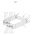
- FIG. 2 is a perspective view of another liquid heater 1 according to the invention shown.
- This liquid heater 1 has a total of four juxtaposed or superimposed connection elements 4, which are liquid-tightly connected to one another via a plurality of tubular sections 3 via the holding elements 5.
- a total of five tubular section 3 can be seen, which consist of an electrically non-conductive material.
- These tubular sections 3 are made of a polymeric material and have on their outer side a metallic coating in the form of a metal foil.
- the tubular sections 3 are dimensioned by a thermal deformation so that they are formed as a stepped, rectangular helix and abut each other with their outer surfaces.
- Such a dimensioned inventive liquid heater 1 can be used as, for example, instantaneous water heater.
Landscapes
- Engineering & Computer Science (AREA)
- Physics & Mathematics (AREA)
- Thermal Sciences (AREA)
- Chemical & Material Sciences (AREA)
- Combustion & Propulsion (AREA)
- Mechanical Engineering (AREA)
- General Engineering & Computer Science (AREA)
- Resistance Heating (AREA)
Applications Claiming Priority (1)
| Application Number | Priority Date | Filing Date | Title |
|---|---|---|---|
| DE202009009340U DE202009009340U1 (de) | 2009-07-07 | 2009-07-07 | Flüssigkeitserhitzer |
Publications (1)
| Publication Number | Publication Date |
|---|---|
| EP2287540A2 true EP2287540A2 (fr) | 2011-02-23 |
Family
ID=42668473
Family Applications (1)
| Application Number | Title | Priority Date | Filing Date |
|---|---|---|---|
| EP20100006929 Withdrawn EP2287540A2 (fr) | 2009-07-07 | 2010-07-05 | Dispositif de chauffage de liquide |
Country Status (2)
| Country | Link |
|---|---|
| EP (1) | EP2287540A2 (fr) |
| DE (1) | DE202009009340U1 (fr) |
Cited By (2)
| Publication number | Priority date | Publication date | Assignee | Title |
|---|---|---|---|---|
| GB2487431A (en) * | 2011-01-22 | 2012-07-25 | Applied Energy Products Ltd | Linear array of electric heating modules |
| CN105698372A (zh) * | 2016-02-05 | 2016-06-22 | 中山市易度工业产品设计有限公司 | 液体加热装置 |
Citations (2)
| Publication number | Priority date | Publication date | Assignee | Title |
|---|---|---|---|---|
| DE10322034A1 (de) | 2003-05-16 | 2004-12-02 | Stiebel Eltron Gmbh & Co. Kg | Flüssigkeitserhitzer |
| DE202007013041U1 (de) | 2007-09-18 | 2007-11-15 | Tsai, Hua-Hsin, Linnei | Wasserhitzermodul |
Family Cites Families (6)
| Publication number | Priority date | Publication date | Assignee | Title |
|---|---|---|---|---|
| DE1091249B (de) * | 1959-03-11 | 1960-10-20 | Licentia Gmbh | Elektrisch beheizter Durchlauferhitzer |
| DE1540728A1 (de) * | 1965-04-15 | 1970-01-29 | Alfred Eckerfeld | Elektrischer Durchlauferhitzer mit einer unmittelbar vom Wasser umspuelten Heizwendel |
| DE2946772A1 (de) * | 1979-11-20 | 1982-01-21 | Helustro-Lufttechnik GmbH, 4005 Meerbusch | Elektro-durchlauferhitzer |
| DE3412390C2 (de) * | 1984-04-03 | 1994-05-05 | Eichenauer Gmbh & Co Kg F | Durchlauferhitzer |
| ATA288784A (de) * | 1984-09-10 | 1985-12-15 | Vaillant Gmbh | Elektrischer heizkoerper |
| DE4400720A1 (de) * | 1994-01-13 | 1995-07-20 | Forbach Gmbh | Heizsystem stabbeheizter Rohr-Durchlauferhitzer für Dreh- und Wechselstrom-Anschluß |
-
2009
- 2009-07-07 DE DE202009009340U patent/DE202009009340U1/de not_active Expired - Lifetime
-
2010
- 2010-07-05 EP EP20100006929 patent/EP2287540A2/fr not_active Withdrawn
Patent Citations (2)
| Publication number | Priority date | Publication date | Assignee | Title |
|---|---|---|---|---|
| DE10322034A1 (de) | 2003-05-16 | 2004-12-02 | Stiebel Eltron Gmbh & Co. Kg | Flüssigkeitserhitzer |
| DE202007013041U1 (de) | 2007-09-18 | 2007-11-15 | Tsai, Hua-Hsin, Linnei | Wasserhitzermodul |
Cited By (3)
| Publication number | Priority date | Publication date | Assignee | Title |
|---|---|---|---|---|
| GB2487431A (en) * | 2011-01-22 | 2012-07-25 | Applied Energy Products Ltd | Linear array of electric heating modules |
| GB2487431B (en) * | 2011-01-22 | 2016-07-13 | Applied Energy Products Ltd | Improvements in water heating |
| CN105698372A (zh) * | 2016-02-05 | 2016-06-22 | 中山市易度工业产品设计有限公司 | 液体加热装置 |
Also Published As
| Publication number | Publication date |
|---|---|
| DE202009009340U1 (de) | 2010-11-18 |
Similar Documents
| Publication | Publication Date | Title |
|---|---|---|
| DE60305516T2 (de) | Beheizte leitung | |
| EP2699414B1 (fr) | Conduite de milieux multicouche pouvant être chauffée électriquement | |
| EP2812581B1 (fr) | Pompe avec chauffage intégré | |
| EP2544949B1 (fr) | Protection de conduites d'eau contre le gel | |
| EP2407069A1 (fr) | Chauffe-eau instantané dynamique | |
| EP2549119A2 (fr) | Pompe | |
| DE112008003310T5 (de) | Heizrohrleitung für den Transport von Fluid | |
| DE102007033166A1 (de) | Wärmetauscher | |
| EP2861914B1 (fr) | Chauffe-eau instantané | |
| DE102010031520A1 (de) | Elektrischer Heizkörper und Durchlauferhitzer | |
| EP1529470B2 (fr) | Module de chauffage avec surface chauffante et chaudière instantanée et procédé pour sa fabrication | |
| WO2012156104A1 (fr) | Chemise de refroidissement pour moteur électrique | |
| EP0819892B1 (fr) | Echangeur de chaleur pour la production d'eau sanitaire | |
| DE202009009340U1 (de) | Flüssigkeitserhitzer | |
| EP1340953B1 (fr) | Echangeur de chaleur, en particulier pour piscines | |
| DE10051756B4 (de) | Wärmetauscher füür Schwimmbäder | |
| DE19908012C2 (de) | Einrichtung zum Ausgleich der Bewegung zweier druckdicht zu verbindender Rohre | |
| EP2543936A2 (fr) | Chauffe-eau instantané | |
| DE202017106495U1 (de) | Beheizbarer flexibler Schlauch mit aufgebrachtem Heizelement | |
| EP2443982B1 (fr) | Appareil ménager doté d'un chauffe-eau instantané | |
| DE102007040076B4 (de) | Heizrohranordnung | |
| DE102013108881A1 (de) | Muffenverbindung | |
| EP4025841A1 (fr) | Dispositif de retenue destiné à retenir un capteur de mesure et à transmettre un signal de mesure électrique | |
| EP4042056B1 (fr) | Conduite de fluide pouvant être chauffée pourvue d'un dispositif de chauffage interne et externe | |
| DE102010035560A1 (de) | Vorrichtung zur induktiven Erwärmung eines Fluids |
Legal Events
| Date | Code | Title | Description |
|---|---|---|---|
| PUAI | Public reference made under article 153(3) epc to a published international application that has entered the european phase |
Free format text: ORIGINAL CODE: 0009012 |
|
| AK | Designated contracting states |
Kind code of ref document: A2 Designated state(s): AL AT BE BG CH CY CZ DE DK EE ES FI FR GB GR HR HU IE IS IT LI LT LU LV MC MK MT NL NO PL PT RO SE SI SK SM TR |
|
| AX | Request for extension of the european patent |
Extension state: BA ME RS |
|
| STAA | Information on the status of an ep patent application or granted ep patent |
Free format text: STATUS: THE APPLICATION IS DEEMED TO BE WITHDRAWN |
|
| 18D | Application deemed to be withdrawn |
Effective date: 20140201 |