EP2543936A2 - Chauffe-eau instantané - Google Patents
Chauffe-eau instantané Download PDFInfo
- Publication number
- EP2543936A2 EP2543936A2 EP12002691A EP12002691A EP2543936A2 EP 2543936 A2 EP2543936 A2 EP 2543936A2 EP 12002691 A EP12002691 A EP 12002691A EP 12002691 A EP12002691 A EP 12002691A EP 2543936 A2 EP2543936 A2 EP 2543936A2
- Authority
- EP
- European Patent Office
- Prior art keywords
- cladding tube
- tubular
- tubular heater
- rib
- projections
- Prior art date
- Legal status (The legal status is an assumption and is not a legal conclusion. Google has not performed a legal analysis and makes no representation as to the accuracy of the status listed.)
- Withdrawn
Links
Images



Classifications
-
- F—MECHANICAL ENGINEERING; LIGHTING; HEATING; WEAPONS; BLASTING
- F24—HEATING; RANGES; VENTILATING
- F24H—FLUID HEATERS, e.g. WATER OR AIR HEATERS, HAVING HEAT-GENERATING MEANS, e.g. HEAT PUMPS, IN GENERAL
- F24H1/00—Water heaters, e.g. boilers, continuous-flow heaters or water-storage heaters
- F24H1/10—Continuous-flow heaters, i.e. heaters in which heat is generated only while the water is flowing, e.g. with direct contact of the water with the heating medium
- F24H1/12—Continuous-flow heaters, i.e. heaters in which heat is generated only while the water is flowing, e.g. with direct contact of the water with the heating medium in which the water is kept separate from the heating medium
- F24H1/14—Continuous-flow heaters, i.e. heaters in which heat is generated only while the water is flowing, e.g. with direct contact of the water with the heating medium in which the water is kept separate from the heating medium by tubes, e.g. bent in serpentine form
- F24H1/142—Continuous-flow heaters, i.e. heaters in which heat is generated only while the water is flowing, e.g. with direct contact of the water with the heating medium in which the water is kept separate from the heating medium by tubes, e.g. bent in serpentine form using electric energy supply
-
- F—MECHANICAL ENGINEERING; LIGHTING; HEATING; WEAPONS; BLASTING
- F24—HEATING; RANGES; VENTILATING
- F24H—FLUID HEATERS, e.g. WATER OR AIR HEATERS, HAVING HEAT-GENERATING MEANS, e.g. HEAT PUMPS, IN GENERAL
- F24H1/00—Water heaters, e.g. boilers, continuous-flow heaters or water-storage heaters
- F24H1/10—Continuous-flow heaters, i.e. heaters in which heat is generated only while the water is flowing, e.g. with direct contact of the water with the heating medium
- F24H1/101—Continuous-flow heaters, i.e. heaters in which heat is generated only while the water is flowing, e.g. with direct contact of the water with the heating medium using electric energy supply
- F24H1/102—Continuous-flow heaters, i.e. heaters in which heat is generated only while the water is flowing, e.g. with direct contact of the water with the heating medium using electric energy supply with resistance
-
- F—MECHANICAL ENGINEERING; LIGHTING; HEATING; WEAPONS; BLASTING
- F24—HEATING; RANGES; VENTILATING
- F24H—FLUID HEATERS, e.g. WATER OR AIR HEATERS, HAVING HEAT-GENERATING MEANS, e.g. HEAT PUMPS, IN GENERAL
- F24H15/00—Control of fluid heaters
- F24H15/10—Control of fluid heaters characterised by the purpose of the control
- F24H15/128—Preventing overheating
-
- F—MECHANICAL ENGINEERING; LIGHTING; HEATING; WEAPONS; BLASTING
- F24—HEATING; RANGES; VENTILATING
- F24H—FLUID HEATERS, e.g. WATER OR AIR HEATERS, HAVING HEAT-GENERATING MEANS, e.g. HEAT PUMPS, IN GENERAL
- F24H15/00—Control of fluid heaters
- F24H15/20—Control of fluid heaters characterised by control inputs
- F24H15/212—Temperature of the water
- F24H15/215—Temperature of the water before heating
-
- F—MECHANICAL ENGINEERING; LIGHTING; HEATING; WEAPONS; BLASTING
- F24—HEATING; RANGES; VENTILATING
- F24H—FLUID HEATERS, e.g. WATER OR AIR HEATERS, HAVING HEAT-GENERATING MEANS, e.g. HEAT PUMPS, IN GENERAL
- F24H15/00—Control of fluid heaters
- F24H15/20—Control of fluid heaters characterised by control inputs
- F24H15/212—Temperature of the water
- F24H15/219—Temperature of the water after heating
-
- F—MECHANICAL ENGINEERING; LIGHTING; HEATING; WEAPONS; BLASTING
- F24—HEATING; RANGES; VENTILATING
- F24H—FLUID HEATERS, e.g. WATER OR AIR HEATERS, HAVING HEAT-GENERATING MEANS, e.g. HEAT PUMPS, IN GENERAL
- F24H15/00—Control of fluid heaters
- F24H15/30—Control of fluid heaters characterised by control outputs; characterised by the components to be controlled
- F24H15/355—Control of heat-generating means in heaters
- F24H15/37—Control of heat-generating means in heaters of electric heaters
-
- F—MECHANICAL ENGINEERING; LIGHTING; HEATING; WEAPONS; BLASTING
- F24—HEATING; RANGES; VENTILATING
- F24H—FLUID HEATERS, e.g. WATER OR AIR HEATERS, HAVING HEAT-GENERATING MEANS, e.g. HEAT PUMPS, IN GENERAL
- F24H9/00—Details
- F24H9/0005—Details for water heaters
- F24H9/001—Guiding means
- F24H9/0015—Guiding means in water channels
-
- F—MECHANICAL ENGINEERING; LIGHTING; HEATING; WEAPONS; BLASTING
- F24—HEATING; RANGES; VENTILATING
- F24H—FLUID HEATERS, e.g. WATER OR AIR HEATERS, HAVING HEAT-GENERATING MEANS, e.g. HEAT PUMPS, IN GENERAL
- F24H9/00—Details
- F24H9/20—Arrangement or mounting of control or safety devices
- F24H9/2007—Arrangement or mounting of control or safety devices for water heaters
- F24H9/2014—Arrangement or mounting of control or safety devices for water heaters using electrical energy supply
- F24H9/2028—Continuous-flow heaters
-
- H—ELECTRICITY
- H05—ELECTRIC TECHNIQUES NOT OTHERWISE PROVIDED FOR
- H05B—ELECTRIC HEATING; ELECTRIC LIGHT SOURCES NOT OTHERWISE PROVIDED FOR; CIRCUIT ARRANGEMENTS FOR ELECTRIC LIGHT SOURCES, IN GENERAL
- H05B3/00—Ohmic-resistance heating
- H05B3/40—Heating elements having the shape of rods or tubes
- H05B3/42—Heating elements having the shape of rods or tubes non-flexible
- H05B3/48—Heating elements having the shape of rods or tubes non-flexible heating conductor embedded in insulating material
- H05B3/50—Heating elements having the shape of rods or tubes non-flexible heating conductor embedded in insulating material heating conductor arranged in metal tubes, the radiating surface having heat-conducting fins
-
- F—MECHANICAL ENGINEERING; LIGHTING; HEATING; WEAPONS; BLASTING
- F24—HEATING; RANGES; VENTILATING
- F24H—FLUID HEATERS, e.g. WATER OR AIR HEATERS, HAVING HEAT-GENERATING MEANS, e.g. HEAT PUMPS, IN GENERAL
- F24H15/00—Control of fluid heaters
- F24H15/30—Control of fluid heaters characterised by control outputs; characterised by the components to be controlled
- F24H15/335—Control of pumps, e.g. on-off control
-
- F—MECHANICAL ENGINEERING; LIGHTING; HEATING; WEAPONS; BLASTING
- F24—HEATING; RANGES; VENTILATING
- F24H—FLUID HEATERS, e.g. WATER OR AIR HEATERS, HAVING HEAT-GENERATING MEANS, e.g. HEAT PUMPS, IN GENERAL
- F24H15/00—Control of fluid heaters
- F24H15/40—Control of fluid heaters characterised by the type of controllers
- F24H15/414—Control of fluid heaters characterised by the type of controllers using electronic processing, e.g. computer-based
Definitions
- the invention relates to a water heater with an inner tubular heater and an outer thereof radially spaced cladding tube, which is preferably connected at its ends tightly connected to the tubular heater, and having connections for the inlet and outlet of a liquid.
- a generic water heater known.
- the cladding has embossments, which together with the jacket tube surface of the tubular heater form a meandering labyrinth for the liquid between inlet and outlet.
- the device for generating steam consists of an elongated heating element that works as a radiant heater, and a surrounding water heater for heating and evaporation of water flowing through with overheating of the steam in the water supply, the steam in the water supply to a temperature above 100 °, is heated in particular over 200 °.
- the water in a channel or hose-like geometry, the water is passed around the heating element helically, so that upon heating or overheating of the water, the heat generated in the heating element must first penetrate the wall surrounding the heating element and then the wall of the channel-like water guidance geometry, in order to be heated or to be given to overheated water. This results in energy losses, since the heat to be transferred from the heating element to the water must penetrate an additional wall. In addition, an individual production is required, which is costly.
- the present invention seeks to provide a water heater of the type mentioned, which is particularly inexpensive to produce, which requires little energy to heat the liquid and low pump power, which also has a long service life having.
- the invention proposes that the tubular heater has on its outer side facing the cladding rib-like projections which form flow channels with the inner shell of the cladding tube, which connect the inlet to the drain.
- the liquid to be heated flows directly around the jacket of the tubular heater, so that no further wall has to be heated by the tubular heater in order to release the heat energy to the liquid to be heated.
- the liquid to be heated flows around it on the outside of the tubular heater formed rib-like projections which are heated by heat conduction from the tubular heater and the increase the effective surface area of the tubular heater.
- Such a water heater with a tubular heater according to the invention is inexpensive and easy to manufacture and has a particularly long service life. In this case, a particularly high proportion of the heat generated by the tubular heater is released to the liquid, so that a high efficiency is achieved.
- the rib-like projections form no or only a slight flow obstacle, which has a favorable effect on the required pump capacity for pumping through the liquid.
- the rib-like projections are arranged helically around the longitudinal central axis of the tubular heater running around.
- the helical shape of the rib-like projections preferably has a very large pitch with a twist angle of about 20 ° to a length of about 200 mm, which corresponds to a pitch of about 3,600 mm. When used as intended, this causes only slight pressure losses.
- the helical shape has only a slight slope, because the angle of rotation, for example, 360 ° to a length of 5 mm to 20 mm, so this represents a strong loss of pressure flow geometry, which is unfavorable.
- the rib-like projections extend parallel to the longitudinal central axis of the tubular heater.
- a parallel along the central longitudinal axis or a preferably around the central longitudinal axis of the tubular heater around helically extending arrangement of the rib-like projections a particularly high heat input into the liquid to be heated to achieve.
- the heat transfer to the liquid to be heated is thereby increased by about a factor of 2 or greater compared to other solutions.
- pressure losses are significantly lower than in other systems with outside circumferential spiral or, for example, meandering cladding.
- the tubular heater is formed by a heating cartridge with a jacket tube of an extruded profile section with therein arranged helically wire heating wire and the heating wire surrounding insulating, in particular quartz sand.
- the extruded profile section of a good heat-conducting material such as aluminum or steel.
- Such a tubular heater with a jacket tube of an extruded section is particularly inexpensive to produce, since only generates a corresponding extruded profile, and then can be cut to length in the desired length.
- an extruded profile can first be produced with rib-like projections extending over its length and uniformly distributed over the circumference. This profile or profile sections cut to length can now be rotated about the longitudinal axis so that a helical shape of the projections formed as longitudinal ribs results.
- Such a tubular heater has a particularly long service life and is inexpensive and easy to produce.
- the surface of the tubular heating element around which the liquid flows or can flow around is roughened or ribbed.
- the inner shell of the cladding tube can also be roughened or corrugated.
- Tubular heater in the liquid to be heated allows.
- the rib-like projections bear against the inner shell of the cladding tube.
- the rib-like projections are arranged forming a flow gap between the outer edge of the rib-like projection and inner shell of the cladding tube within the cladding tube.
- the tubular heating element passes through the cladding tube in a fluid-tight manner on one end face or on both end faces and electrical continuity on the penetrating region Having connecting elements, which protrude from the end face of the tubular heater.
- the tubular heater can be connected in a quick and simple manner with electrical connection means, for example for power supply and / or control, so that, for example, for maintenance or replacement of a tubular heater, this off in a quick and easy way and can be installed again ,
- At least one temperature sensor is arranged on the cladding tube, which protrudes into the gap between the cladding tube and tubular heater.
- a first temperature sensor and near the drain a second temperature sensor is arranged, which projects in each case into the gap between the cladding tube and tubular heater.
- a control unit that evaluates the signals or measured values of the temperature sensor can be signaled to increase the power supply to the heating element to achieve an increase in temperature, or to increase the flow rate or lower accordingly.
- the cladding tube is in two parts, for example longitudinally split or transversely divided.
- the cladding tube consists of two approximately tubular sections, each having at its connection region with the other tubular portion a flange, by means of which the two tubular portions are fluid-tight connected or connected to each other.
- the tubular sections formed with a flange can be connected in a simple manner by connecting the flanges quickly and thereby fluid-tight and also separated again, for example, to exchange the tubular heater therein.
- the cladding tube or the tubular sections are made of plastic.
- Such a plastic existing cladding can be inexpensive and easy, for example in Plastic injection molding are produced and has a long service life.
- tubular sections are connected to one another by screwing, clipping, locking, gluing or by plastic welding.
- At least one over-temperature protection fuse is arranged inside the tubular heater.
- the over-temperature protection fuse is formed by a fuse or bi-metal fuse arranged on or near each end face.
- an overtemperature protection fuse near each end allows communication with a control unit, for example, a quick shutdown by the control unit at an undesirable excess temperature, in particular to avoid damage to the water heater.
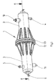
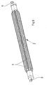
- FIGS. 1 and 2 a flow heater 1 with a tubular heater 2 and an outer spaced cladding tube 3 is shown. Between tubular heater 2 and cladding tube 3, a flow gap for the flowing through, to be heated medium is formed.
- the cladding tube 3 is penetrated at its front ends tightly from the tubular heater 2.
- the cladding tube 3 has connections 4,5 for the inlet (at 4) and the outlet (at 5) of a liquid.
- the tubular body 2 has rib-like projections 6 on its outer side facing the jacket tube 3, which form flow channels with the inner jacket of the jacket tube 3.
- the rib-like projections 6 extend continuously over almost the entire length of the tubular heater 2 and end shortly before the terminals 4.5.
- the flow channels connect the inlet (port 4) with the drain (port 5).
- the liquid to be heated flows around the jacket of the tubular heater 2 and its rib-like projections 6 directly, so that an excellent heat transfer to the liquid flowing through arises.
- a tubular heater 2 has a particularly high degree of efficiency and is also inexpensive and easy to manufacture and has a long service life.
- the rib-like projections 6 are arranged helically around the longitudinal center axis of the tubular heater 2 extending around. As a result, a particularly efficient heat transfer from the tubular heater 2 is achieved in the liquid to be heated, wherein the liquid is circulated quasi turbulent in the boundary layer.
- the rib-like projections 6 are arranged to extend parallel to the longitudinal central axis of the tubular heater.
- the tubular heater 2 is formed from a heating cartridge with a jacket tube of an extruded profile section with heating wire 7 arranged therein in the manner of a helix and the insulating wire surrounding the heating wire 7, in the form of quartz sand 8 in the exemplary embodiment.
- the extruded profile section consists of a good heat-conducting material, such as aluminum or steel. Such a tubular heater 2 is inexpensive and easy to manufacture and has a very long service life.
- the surface of the tubular heating element 2 that flows around or can be flowed around by the liquid can be roughened or ribbed in order to allow a particularly high heat transfer into the liquid to be heated.
- the rib-like projections 6 can either be arranged on the inner jacket of the cladding tube 3 or preferably a flow gap between the outer peripheral edge of the rib-like projection 6 and the inner jacket of the cladding tube 3 forming within the cladding tube 3.
- the tubular heating element 2 passes through the cladding tube 3 in a fluid-tight manner on both end faces, wherein electrical connection elements 9 are arranged on the outer regions and protrude out of the tubular heating element 2 on the front side and can thus be connected in a simple manner to corresponding connection means, for example to a control unit and / or a current source are.
- FIG. 2 It can be seen that a first temperature sensor 10 and close to the outlet 5, a second temperature sensor 11 is disposed within the cladding tube 3 near the inlet 4, each temperature sensor 10,11 respectively projects into the gap between the cladding tube 3 and 2 tubular heater to those there existing temperatures of the liquid to measure.
- the measurement signals are transmitted via line connections to corresponding evaluation means such as an electrical or electronic control unit, by means of which the power of the tubular heater 2 and / or the pump power of a liquid transport pump is controlled.
- the cladding tube 3 is in two parts, namely transversely divided formed.
- the cladding tube 3 may be formed longitudinally divided.
- the cladding tube 3 in the embodiment consists of two approximately tubular sections, each having a flange 12, 13 at its connection region with the other tubular portion.
- the tubular sections are connected to one another at their flanges 12,13 fluid-tight manner or connected (see FIG. 1 and 2 ) and consist in the embodiment of plastic.
- Such tubular sections are inexpensive and easy to produce, for example by means of plastic injection molding and thereby have a long service life.
- the tubular sections are screwed together in the region of their flanges 12,13.
- the tubular sections can also be connected to each other by clipping, locking, gluing or by plastic welding.
- an overtemperature protection fuse 14 is arranged within the tubular heater 2 in the exemplary embodiment near each end face.
- the overtemperature protection fuse 14 can be formed for example by a fuse or a bi-metal fuse.
Landscapes
- Engineering & Computer Science (AREA)
- Physics & Mathematics (AREA)
- Thermal Sciences (AREA)
- Chemical & Material Sciences (AREA)
- Combustion & Propulsion (AREA)
- Mechanical Engineering (AREA)
- General Engineering & Computer Science (AREA)
- Instantaneous Water Boilers, Portable Hot-Water Supply Apparatuses, And Control Of Portable Hot-Water Supply Apparatuses (AREA)
- Pipe Accessories (AREA)
Applications Claiming Priority (1)
| Application Number | Priority Date | Filing Date | Title |
|---|---|---|---|
| DE102011106425A DE102011106425A1 (de) | 2011-07-02 | 2011-07-02 | Durchlauferhitzer |
Publications (2)
| Publication Number | Publication Date |
|---|---|
| EP2543936A2 true EP2543936A2 (fr) | 2013-01-09 |
| EP2543936A3 EP2543936A3 (fr) | 2015-09-02 |
Family
ID=46000686
Family Applications (1)
| Application Number | Title | Priority Date | Filing Date |
|---|---|---|---|
| EP12002691.9A Withdrawn EP2543936A3 (fr) | 2011-07-02 | 2012-04-18 | Chauffe-eau instantané |
Country Status (2)
| Country | Link |
|---|---|
| EP (1) | EP2543936A3 (fr) |
| DE (1) | DE102011106425A1 (fr) |
Cited By (3)
| Publication number | Priority date | Publication date | Assignee | Title |
|---|---|---|---|---|
| CN105188165A (zh) * | 2015-09-29 | 2015-12-23 | 安徽省宁国市天成电机有限公司 | 一种多功能加热器 |
| WO2017114693A1 (fr) | 2015-12-28 | 2017-07-06 | C3 Casting Competence Center Gmbh | Chauffe-eau instantané |
| FR3118903A1 (fr) * | 2021-01-19 | 2022-07-22 | Valeo Systemes Thermiques | Dispositif de chauffage électrique et procédé de fabrication d’une résistance chauffante d’un tel dispositif |
Citations (2)
| Publication number | Priority date | Publication date | Assignee | Title |
|---|---|---|---|---|
| DE102009010989A1 (de) | 2009-02-19 | 2010-09-02 | E.G.O. Elektro-Gerätebau GmbH | Verfahren und Vorrichtung zur Dampferzeugung |
| DE102009024059A1 (de) | 2009-06-05 | 2010-12-09 | Eichenauer Heizelemente Gmbh & Co. Kg | Durchlauferhitzer |
Family Cites Families (7)
| Publication number | Priority date | Publication date | Assignee | Title |
|---|---|---|---|---|
| US3835294A (en) * | 1973-04-06 | 1974-09-10 | Binks Mfg Co | High pressure electric fluid heater |
| US4480172A (en) * | 1982-06-17 | 1984-10-30 | Henry Ciciliot | Electric heat exchanger for simultaneously vaporizing two different fluids |
| US6282370B1 (en) * | 1998-09-03 | 2001-08-28 | Balboa Instruments, Inc. | Control system for bathers |
| US6944394B2 (en) * | 2002-01-22 | 2005-09-13 | Watlow Electric Manufacturing Company | Rapid response electric heat exchanger |
| DE20321667U1 (de) * | 2003-05-16 | 2008-10-09 | Stiebel Eltron Gmbh & Co. Kg | Flüssigkeitserhitzer |
| WO2005057090A1 (fr) * | 2003-12-10 | 2005-06-23 | Matsushita Electric Industrial Co., Ltd. | Echangeur thermique et dispositif d'epuration |
| DE102008018658A1 (de) * | 2008-04-11 | 2009-10-15 | A. Kayser Automotive Systems Gmbh | Beheizbares Leitungselement für ein Fluid |
-
2011
- 2011-07-02 DE DE102011106425A patent/DE102011106425A1/de not_active Withdrawn
-
2012
- 2012-04-18 EP EP12002691.9A patent/EP2543936A3/fr not_active Withdrawn
Patent Citations (2)
| Publication number | Priority date | Publication date | Assignee | Title |
|---|---|---|---|---|
| DE102009010989A1 (de) | 2009-02-19 | 2010-09-02 | E.G.O. Elektro-Gerätebau GmbH | Verfahren und Vorrichtung zur Dampferzeugung |
| DE102009024059A1 (de) | 2009-06-05 | 2010-12-09 | Eichenauer Heizelemente Gmbh & Co. Kg | Durchlauferhitzer |
Cited By (3)
| Publication number | Priority date | Publication date | Assignee | Title |
|---|---|---|---|---|
| CN105188165A (zh) * | 2015-09-29 | 2015-12-23 | 安徽省宁国市天成电机有限公司 | 一种多功能加热器 |
| WO2017114693A1 (fr) | 2015-12-28 | 2017-07-06 | C3 Casting Competence Center Gmbh | Chauffe-eau instantané |
| FR3118903A1 (fr) * | 2021-01-19 | 2022-07-22 | Valeo Systemes Thermiques | Dispositif de chauffage électrique et procédé de fabrication d’une résistance chauffante d’un tel dispositif |
Also Published As
| Publication number | Publication date |
|---|---|
| DE102011106425A1 (de) | 2013-01-03 |
| EP2543936A3 (fr) | 2015-09-02 |
Similar Documents
| Publication | Publication Date | Title |
|---|---|---|
| EP2926623B1 (fr) | Élément chauffant et dispositif de chauffage de processus | |
| EP2296433B1 (fr) | Dispositif de chauffage électrique et procédé de fabrication d'un dispositif de chauffage électrique | |
| DE102012202065B3 (de) | Pumpe und Verfahren zum Beheizen einer Pumpe | |
| DE2250778A1 (de) | Elektrisches heizgeraet und verfahren zu seiner herstellung | |
| EP2410813B1 (fr) | Radiateur électrique et chauffe-eau instantané | |
| EP2592982A2 (fr) | Dispositif de chauffe instantané dynamique | |
| EP1718115B1 (fr) | Element de chauffage tubulaire avec un conducteur chauffant helicoidal tronconique | |
| DE102018122414B4 (de) | Temperiervorrichtung und Verfahren zum Temperieren eines Elektromoduls | |
| WO2015103656A1 (fr) | Dispositif de conversion d'une énergie thermique | |
| WO2012156104A1 (fr) | Chemise de refroidissement pour moteur électrique | |
| DE102011106425A1 (de) | Durchlauferhitzer | |
| DE102011007542B4 (de) | Durchlauferhitzer | |
| DE102008018658A1 (de) | Beheizbares Leitungselement für ein Fluid | |
| DE19543083C2 (de) | Verfahren zum Verbinden aus schweißfähigem Kunststoff bestehender Wellrohre | |
| EP1340953B1 (fr) | Echangeur de chaleur, en particulier pour piscines | |
| DE4212074C1 (en) | Electric continuous flow meter e.g. for coffee machine - has tubular heaters pressed so that walls of flow tube have recesses altering cross-section | |
| EP2092863B1 (fr) | Chauffe-eau instantané | |
| EP2295888B1 (fr) | Accumulateur d'eau chaude | |
| DE1802729C3 (de) | Vorrichtung zum Erhitzen von Flüssigkeiten beziehungsweise Gasen | |
| DE10051756A1 (de) | Wärmetauscher füür Schwimmbäder | |
| DE1957221A1 (de) | Waermeaustauscher aus Rohrelementen,insbesondere fuer Raumbeheizung | |
| EP4042056B1 (fr) | Conduite de fluide pouvant être chauffée pourvue d'un dispositif de chauffage interne et externe | |
| EP2087786A1 (fr) | Plaque de sol pouvant être chauffée pour un sol d'écurie | |
| EP2287540A2 (fr) | Dispositif de chauffage de liquide | |
| DE19519121C1 (de) | Vorrichtung zum Erhitzen von Flüssigkeiten |
Legal Events
| Date | Code | Title | Description |
|---|---|---|---|
| PUAI | Public reference made under article 153(3) epc to a published international application that has entered the european phase |
Free format text: ORIGINAL CODE: 0009012 |
|
| AK | Designated contracting states |
Kind code of ref document: A2 Designated state(s): AL AT BE BG CH CY CZ DE DK EE ES FI FR GB GR HR HU IE IS IT LI LT LU LV MC MK MT NL NO PL PT RO RS SE SI SK SM TR |
|
| AX | Request for extension of the european patent |
Extension state: BA ME |
|
| PUAL | Search report despatched |
Free format text: ORIGINAL CODE: 0009013 |
|
| AK | Designated contracting states |
Kind code of ref document: A3 Designated state(s): AL AT BE BG CH CY CZ DE DK EE ES FI FR GB GR HR HU IE IS IT LI LT LU LV MC MK MT NL NO PL PT RO RS SE SI SK SM TR |
|
| AX | Request for extension of the european patent |
Extension state: BA ME |
|
| RIC1 | Information provided on ipc code assigned before grant |
Ipc: F24H 1/10 20060101ALI20150729BHEP Ipc: F24H 1/14 20060101AFI20150729BHEP Ipc: F24H 9/20 20060101ALI20150729BHEP Ipc: H05B 3/50 20060101ALI20150729BHEP Ipc: F24H 9/00 20060101ALI20150729BHEP |
|
| STAA | Information on the status of an ep patent application or granted ep patent |
Free format text: STATUS: THE APPLICATION IS DEEMED TO BE WITHDRAWN |
|
| 18D | Application deemed to be withdrawn |
Effective date: 20160303 |