EP2289652B2 - Dispositif et procédé de fabrication générative - Google Patents
Dispositif et procédé de fabrication générative Download PDFInfo
- Publication number
- EP2289652B2 EP2289652B2 EP09168566.9A EP09168566A EP2289652B2 EP 2289652 B2 EP2289652 B2 EP 2289652B2 EP 09168566 A EP09168566 A EP 09168566A EP 2289652 B2 EP2289652 B2 EP 2289652B2
- Authority
- EP
- European Patent Office
- Prior art keywords
- substrate plate
- layer
- plate segment
- segments
- products
- Prior art date
- Legal status (The legal status is an assumption and is not a legal conclusion. Google has not performed a legal analysis and makes no representation as to the accuracy of the status listed.)
- Active
Links
Images


Classifications
-
- B—PERFORMING OPERATIONS; TRANSPORTING
- B29—WORKING OF PLASTICS; WORKING OF SUBSTANCES IN A PLASTIC STATE IN GENERAL
- B29C—SHAPING OR JOINING OF PLASTICS; SHAPING OF MATERIAL IN A PLASTIC STATE, NOT OTHERWISE PROVIDED FOR; AFTER-TREATMENT OF THE SHAPED PRODUCTS, e.g. REPAIRING
- B29C64/00—Additive manufacturing, i.e. manufacturing of three-dimensional [3D] objects by additive deposition, additive agglomeration or additive layering, e.g. by 3D printing, stereolithography or selective laser sintering
- B29C64/10—Processes of additive manufacturing
- B29C64/171—Processes of additive manufacturing specially adapted for manufacturing multiple 3D objects
- B29C64/176—Sequentially
-
- A—HUMAN NECESSITIES
- A61—MEDICAL OR VETERINARY SCIENCE; HYGIENE
- A61C—DENTISTRY; APPARATUS OR METHODS FOR ORAL OR DENTAL HYGIENE
- A61C13/00—Dental prostheses; Making same
- A61C13/0003—Making bridge-work, inlays, implants or the like
- A61C13/0006—Production methods
- A61C13/0013—Production methods using stereolithographic techniques
-
- A—HUMAN NECESSITIES
- A61—MEDICAL OR VETERINARY SCIENCE; HYGIENE
- A61C—DENTISTRY; APPARATUS OR METHODS FOR ORAL OR DENTAL HYGIENE
- A61C13/00—Dental prostheses; Making same
- A61C13/0003—Making bridge-work, inlays, implants or the like
- A61C13/0006—Production methods
- A61C13/0018—Production methods using laser
-
- B—PERFORMING OPERATIONS; TRANSPORTING
- B22—CASTING; POWDER METALLURGY
- B22F—WORKING METALLIC POWDER; MANUFACTURE OF ARTICLES FROM METALLIC POWDER; MAKING METALLIC POWDER; APPARATUS OR DEVICES SPECIALLY ADAPTED FOR METALLIC POWDER
- B22F10/00—Additive manufacturing of workpieces or articles from metallic powder
- B22F10/20—Direct sintering or melting
- B22F10/28—Powder bed fusion, e.g. selective laser melting [SLM] or electron beam melting [EBM]
-
- B—PERFORMING OPERATIONS; TRANSPORTING
- B29—WORKING OF PLASTICS; WORKING OF SUBSTANCES IN A PLASTIC STATE IN GENERAL
- B29C—SHAPING OR JOINING OF PLASTICS; SHAPING OF MATERIAL IN A PLASTIC STATE, NOT OTHERWISE PROVIDED FOR; AFTER-TREATMENT OF THE SHAPED PRODUCTS, e.g. REPAIRING
- B29C64/00—Additive manufacturing, i.e. manufacturing of three-dimensional [3D] objects by additive deposition, additive agglomeration or additive layering, e.g. by 3D printing, stereolithography or selective laser sintering
- B29C64/10—Processes of additive manufacturing
- B29C64/141—Processes of additive manufacturing using only solid materials
- B29C64/153—Processes of additive manufacturing using only solid materials using layers of powder being selectively joined, e.g. by selective laser sintering or melting
-
- B—PERFORMING OPERATIONS; TRANSPORTING
- B22—CASTING; POWDER METALLURGY
- B22F—WORKING METALLIC POWDER; MANUFACTURE OF ARTICLES FROM METALLIC POWDER; MAKING METALLIC POWDER; APPARATUS OR DEVICES SPECIALLY ADAPTED FOR METALLIC POWDER
- B22F10/00—Additive manufacturing of workpieces or articles from metallic powder
- B22F10/30—Process control
- B22F10/32—Process control of the atmosphere, e.g. composition or pressure in a building chamber
-
- B—PERFORMING OPERATIONS; TRANSPORTING
- B22—CASTING; POWDER METALLURGY
- B22F—WORKING METALLIC POWDER; MANUFACTURE OF ARTICLES FROM METALLIC POWDER; MAKING METALLIC POWDER; APPARATUS OR DEVICES SPECIALLY ADAPTED FOR METALLIC POWDER
- B22F10/00—Additive manufacturing of workpieces or articles from metallic powder
- B22F10/60—Treatment of workpieces or articles after build-up
- B22F10/66—Treatment of workpieces or articles after build-up by mechanical means
-
- B—PERFORMING OPERATIONS; TRANSPORTING
- B22—CASTING; POWDER METALLURGY
- B22F—WORKING METALLIC POWDER; MANUFACTURE OF ARTICLES FROM METALLIC POWDER; MAKING METALLIC POWDER; APPARATUS OR DEVICES SPECIALLY ADAPTED FOR METALLIC POWDER
- B22F10/00—Additive manufacturing of workpieces or articles from metallic powder
- B22F10/60—Treatment of workpieces or articles after build-up
- B22F10/68—Cleaning or washing
-
- B—PERFORMING OPERATIONS; TRANSPORTING
- B22—CASTING; POWDER METALLURGY
- B22F—WORKING METALLIC POWDER; MANUFACTURE OF ARTICLES FROM METALLIC POWDER; MAKING METALLIC POWDER; APPARATUS OR DEVICES SPECIALLY ADAPTED FOR METALLIC POWDER
- B22F12/00—Apparatus or devices specially adapted for additive manufacturing; Auxiliary means for additive manufacturing; Combinations of additive manufacturing apparatus or devices with other processing apparatus or devices
- B22F12/10—Auxiliary heating means
- B22F12/13—Auxiliary heating means to preheat the material
-
- B—PERFORMING OPERATIONS; TRANSPORTING
- B22—CASTING; POWDER METALLURGY
- B22F—WORKING METALLIC POWDER; MANUFACTURE OF ARTICLES FROM METALLIC POWDER; MAKING METALLIC POWDER; APPARATUS OR DEVICES SPECIALLY ADAPTED FOR METALLIC POWDER
- B22F12/00—Apparatus or devices specially adapted for additive manufacturing; Auxiliary means for additive manufacturing; Combinations of additive manufacturing apparatus or devices with other processing apparatus or devices
- B22F12/80—Plants, production lines or modules
- B22F12/82—Combination of additive manufacturing apparatus or devices with other processing apparatus or devices
- B22F12/86—Serial processing with multiple devices grouped
-
- Y—GENERAL TAGGING OF NEW TECHNOLOGICAL DEVELOPMENTS; GENERAL TAGGING OF CROSS-SECTIONAL TECHNOLOGIES SPANNING OVER SEVERAL SECTIONS OF THE IPC; TECHNICAL SUBJECTS COVERED BY FORMER USPC CROSS-REFERENCE ART COLLECTIONS [XRACs] AND DIGESTS
- Y02—TECHNOLOGIES OR APPLICATIONS FOR MITIGATION OR ADAPTATION AGAINST CLIMATE CHANGE
- Y02P—CLIMATE CHANGE MITIGATION TECHNOLOGIES IN THE PRODUCTION OR PROCESSING OF GOODS
- Y02P10/00—Technologies related to metal processing
- Y02P10/25—Process efficiency
Definitions
- the invention relates to a method for producing products with an individual geometry, in particular dentures or dental accessories, with the steps of producing a number of products on the surface of a substrate plate by means of selective curing, in particular by means of selective sintering or melting, in which the material is applied in successive layers After each layer application, one or more predetermined areas of the applied layer are selectively cured by means of high-energy radiation and connected to one or more areas of the underlying layer, the predetermined areas being predetermined based on a cross-sectional geometry of the product in the respective layer.
- a further aspect of the invention is a device for carrying out such a method.
- Additive manufacturing processes i.e. manufacturing processes in which a material is formed into an individual product in an additive manufacturing process, are used in the manufacture of prototypes and are now also used in product manufacture, especially in the manufacture of individually shaped products or small series application found.
- EP 1 021 997 it is known, for example, to produce individually shaped dentures or dental accessories by means of a selective laser sintering process under certain parameters.
- SLS selective laser sintering or laser melting process
- other additive manufacturing processes can also be suitable for other products, for example processes in which a granulate or other solid material is blown through a high-energy beam, such as sintered or melted, for example a laser beam or electron beam, and thus bonded and cured, or processes in which a plastic in solid or liquid form is selectively cured by photopolymerization using a high-energy beam, such as a laser beam or collimated light beam.
- a fundamental problem of additive manufacturing processes is the long period of time that elapses between the creation of the manufacturing data and the completion of the product. It is known to generatively build up several products on a substrate plate at the same time in order to increase the number of products manufactured in a certain period of time. This procedure is particularly useful for products with very small dimensions in relation to the dimensions of the substrate plate and leads to an effective increase in productivity.
- WO 2008/128502 a device is known which follows the same basic idea and provides a conveying device within the production device, with which one or more construction containers as well as dosing or storage containers can be conveyed in order to achieve simple, fast and safe powder handling within the production device.
- a conveying device within the production device, with which one or more construction containers as well as dosing or storage containers can be conveyed in order to achieve simple, fast and safe powder handling within the production device.
- products can be manufactured quickly in one construction container using one powder material and then, after these products have been completed, products can be manufactured in a second construction container using a different powder material.
- the manufacturing process requires at least as long as the time between the creation of the manufacturing data for all products on the substrate plate and the completion of the products, so that the manufacturing with regard to each one of a plurality of products that are built up continues takes a relatively long time ago.
- WO 2004/014636 a method for the layer-by-layer generative production of three-dimensional objects is known, in which several objects are produced simultaneously in two construction areas. here a layer is applied in one construction area and selective curing is achieved in another construction area by means of radiation.
- Four process chambers are provided, which can be in the form of spatially separate individual chambers or as partial areas of two double chambers or a quadruple chamber.
- a laser can be connected to one of the process chambers via a switching device.
- the device described in this way and the method described for the additive manufacturing of products with this device has the disadvantage that separate control of the application process in each of the process chambers is required for the purpose of simultaneous production with alternating curing and layer application in the respective process chambers.
- the manufacturing process and the device are complex both in terms of structure and control and can therefore contribute to efficiency in terms of productivity manufacturing of numerous small products and the time that elapses between the completion of a product's manufacturing data and the completion of the product itself.
- a device for producing a three-dimensional object is known.
- one or more construction platforms are provided on a platform support, which serve as a construction base or base for an object to be formed.
- the construction platforms are attached to the platform support using positioning pins and clamping elements.
- the platform support is attached to a base plate which can be raised and lowered in the vertical direction by means of a height adjustment device.
- Another problem in the generative manufacturing of small products which is to be understood as meaning products whose base area is smaller, in particular by at least one order of magnitude smaller than the surface of the substrate plate, is that in many areas of application with individual product geometries, generative manufacturing is considered to be made-to-order takes place, such as in the manufacture of dentures in dental laboratories.
- the individual orders typically do not arrive at the same time but at different times when the user of the manufacturing device receives them.
- the user has to bundle several orders in order to manufacture the products contained in the bundled orders on one substrate plate at the same time.
- this creates a significant delay between the receipt of the order and the completion of the product, especially for the order received first.
- the method according to the invention is characterized in that a substrate plate is provided on which a first and a further product can be produced simultaneously in a first and a corresponding further substrate plate segment and these substrate plate segments are detachably connected to one another or to a base support.
- This makes it possible to use a single substrate plate segment to be removed after completion of the product built on it, in order to be able to detach the product from the substrate plate segment, while another product on another substrate plate segment continues to be produced generatively.
- the material layers can be applied to the at least two substrate plate segments in such a way that at least one of the material layers extends over both substrate plate segments.
- the method can proceed in such a way that a material layer is first applied to the at least two substrate plate segments and this material layer is selectively cured in the area above both substrate plate segments.
- the substrate plate segments can in particular interact with a single coating device in such a way that a product is built up on a substrate plate segment in a first production stage, for example with an nth layer above the substrate plate and another product is built up on another substrate plate segment in a different production stage, for example with an m-th built-up layer above the substrate plate, where m is not equal to n and the n-th and m-th layers are applied in one operation by the coating device.
- the production start time can be determined individually for each substrate plate segment and accordingly an individual production end time can also be achieved for each substrate plate segment. In this way, the time it takes to manufacture an individual product is significantly reduced.
- the substrate plate can be divided into two, three or more substrate plate segments.
- this subdivision is to be understood in particular as an actual physical subdivision into individual components which can be assembled accordingly to form a substrate plate.
- layers can be applied to all substrate plate segments with a single, common layer application device, which is preferred due to the efficient production associated therewith.
- the substrate plate segments can be advantageous to coat with material by means of separate layer application devices, whereby it should also be understood here that in the method according to the invention the start of production and a corresponding end of production of the products on the various substrate plate segments take place with a time delay, but on several Substrate plate segments, a simultaneous production preferably takes place with a simultaneous layer application on all substrate plate segments and subsequent selective curing of certain areas for the generative manufacture of products for the purpose of high productivity.
- the substrate plate segments are provided next to one another in such a way that no material can pass between the substrate plate segments.
- a corresponding seal can be provided between the individual substrate plate segments for this purpose, or the substrate plate segments can be joined together in such a way that material can not penetrate between the substrate plate segments.
- the substrate plate segments are designed as segments of an endless conveyor device.
- the substrate plate segments can, for example, be attached to an endless conveyor belt or connected to one another in such a way that they form such an endless conveyor belt in the form of a link chain.
- the substrate plate segments can be moved in a sequential manner along an upper strand and a lower strand, with the layer application and the selective layer curing taking place during the movement along the upper strand.
- the removal of non-hardened, applied material from the space between the manufactured products and the removal of the products can also take place in the area of the upper run, for example by appropriate suction devices or mechanical separating devices.
- the substrate plate segments are designed and arranged in such a way that the first product or a group of first products is built up on a single substrate plate segment and the further product or a group of further products is built up on one or more further substrate plate segments.
- one or more products can be produced on a single substrate plate segment, in order in this way to produce small products in a very high productivity produce fast production times.
- a group of several products can be produced on two or more substrate plate segments. This can be particularly necessary for products that extend very far in only one specific direction.
- a product can be produced whose length extends over several substrate bed segments. If a number of such products are to be manufactured, then, according to this development, a group can be formed by such products and this group can then be manufactured over a number of substrate plate segments.
- the material is applied to the substrate sheet in a quasi-continuous process in a first production section and selectively predetermined areas of each applied layer are cured and completely cured products are removed quasi-continuously in a second production section.
- This manufacturing method enables high-quality generative manufacturing in a first manufacturing section and, at the same time, removal of finished products in a second manufacturing section, which does not negatively affect this generative manufacturing, which is spaced apart from the first manufacturing section.
- This can be achieved in particular by arranging the substrate plate segments on an endless conveyor belt or by forming such a belt with the substrate plate segments and conveying the substrate plate segments accordingly from the first to the second production section.
- the first production section can be kept in a closed, controlled, in particular inert atmosphere in order to be able to set the boundary conditions required for generative production using certain methods, whereas in the second production section the products are discharged, or the second production section lock or the products are already discharged from the controlled atmosphere during the transition from the first to the second production section.
- a material layer is applied above at least two, preferably several, substrate plate segments
- the material layer is selectively cured, and that the maximum distance between the first substrate plate segment and one for manufacturing the first product thereon applied layer differs in at least one, preferably several, in particular all process stages from the maximum distance between the further substrate plate segment and a layer applied thereto for the production of the further product.
- a process stage comprises the sequence of layer application and selective curing and is consequently carried out repeatedly, resulting in successive process stages.
- a first and second process step is carried out in succession and in this case at least two, in particular several, in each case or a layer of material is applied to all substrate plate segments in one operation and this is subsequently selectively cured in order to generatively produce a number of products on the corresponding number of substrate plate segments.
- the layer is applied to the substrate plate segments in such a way that the distance between the applied layer and the substrate plate segments is different for at least two, in particular for each, substrate plate segment. It should be understood that this maximum distance is different during the application of the layer and also or only during the selective curing.
- This distance can differ in only one of several subsequent process stages, each of which consists of the sequence of a layer application and the selective curing of this layer, but in particular the distance can differ in all process stages, i.e. typically that the sum of the layers applied above one Substrate plate segment is different from the sum of the layers applied above another substrate plate segment, for example because the joint application to the two substrate plate segments only started at a point in time when one or more layers had already been applied to one of the two substrate plate segments.
- the method can be implemented, for example, in such a way that the substrate plate segments can be moved individually with regard to their height in order to achieve in this way that although a layer is applied to all substrate plate segments in a common plane, the distance between this layer and the Substrate plate segments is different for each substrate plate segment, or by the layer application device is vertically adjusted during the application process between the substrate plate segments.
- the method further by the steps of removing material which is arranged on the first substrate plate segment and which has not been cured, without thereby removing material of a further substrate plate segment, and subsequent removal of the material arranged on the further substrate plate segment, which has not been cured.
- the uncured material can be removed in such a way that a neighboring area is not affected and the uncured material remains in this neighboring area.
- the uncured material has a support function and serves to accommodate and carry overlying layers. The uncured material should therefore generally not be removed before the product has been fully built up and cured.
- the material removal device can accomplish the material removal without affecting the immediately adjacent substrate plate segment here. This enables rapid and quasi-continuous production and avoids providing a safety distance between the layer application device and the material removal device.
- a first phase of the manufacturing process only layer areas of a layer are selectively cured which are used to manufacture the first product and in a final phase of the manufacturing process only layer areas of a layer are selectively cured which are used to manufacture the further product and preferably in a middle phase of the production process lying between the first and the last phase, layer regions of a layer are cured, which are used for the production of the first and the further product.
- a partition is provided between the substrate plate segments, which partition separates the installation space above each substrate plate segment from the installation space above an adjacent substrate plate segment.
- a partition enables or simplifies the removal of uncured material above a substrate plate segment without affecting the uncured material in a substrate plate segment adjacent thereto.
- a partition wall can be provided as part of the production device and in this case can be designed in such a way, for example, that it is tracked simultaneously with the layer application in order to have an exact height or slightly less than this exact height that the corresponds to the upper layer surface of the material application in the area between two substrate plate segments.
- the partition is produced by curing the applied material during the manufacturing process of the product.
- a partition wall is produced from the applied material at the edge of a substrate plate segment during the production process.
- This procedure has the advantage that there is no need for structurally complex adjustments to the partition wall. Instead, a corresponding partition wall is built up along the edge area of a substrate plate segment, which grows higher with each layer application and in this way is tracked to the total height of the material layer bed. The dividing wall can then be removed when removing the products from the substrate plate segment or in the course of removing uncured material from the adjacent substrate plate segment.
- the two aforementioned embodiments can be further developed in that the partition wall between two substrate plate segments is connected to at least one of the two substrate plate segments.
- the partition wall between two substrate plate segments is connected to at least one of the two substrate plate segments.
- each substrate plate segment is moved individually in relation to the layer application device in such a way that the distance perpendicular to the surface of the substrate plate and the layer applied with a layer application device is changed and the resulting height of the material bed on a substrate plate segment is different from the Height of the material bed is on another substrate plate segment.
- the height of each substrate plate segment can be moved individually, for example by means of an actuator that acts alternately on the substrate plate segments or by means of a plurality of actuators, each of which is provided for one substrate plate segment. The result of this is that the substrate plate segments can be placed at different heights in order to then subsequently apply a layer of material in a plane above the substrate plate segments.
- This material layer is then at an individually different distance from the respective substrate plate segments, ie in particular at an individual distance from the plane of the surface of the substrate plate segments on which the first material layer is placed on the respective substrate plate segment has been applied.
- the embodiment is suitable for generatively producing a product in a first process stage on a first substrate plate segment and another product in a different production stage on another substrate plate segment with a common layer application on the two substrate plate segments and can be applied to a corresponding number of substrate plate segments with a corresponding number of products in different process stages be applied.
- the hardened areas of the previously applied layer are surface-ground before each application of material.
- the geometric precision of the generative manufacturing process is further increased by such surface processing, which can be carried out in particular as grinding, but also by other machining manufacturing processes with a geometrically defined or geometrically undefined cutting edge.
- such a machining operation provides a defined bearing surface and connection point for the layer above and for the areas to be cured therein.
- a defined layer thickness is set by the machining, which is advantageous for a reproducible geometric manufacturing result.
- a single radiation source in particular a single beam path of a single radiation source, is used to cure the first and the at least one further product, in particular all further products.
- multiple radiation sources or multiple beam paths of a single radiation source can also be used to speed up the manufacturing process.
- the production method according to the invention is characterized in particular by the fact that it produces several products at the same time and these products are in different production stages, i.e. in particular are made up of a different number of layers.
- both the application of a layer can be carried out by a single layer application device for all substrate plate segments and products to be manufactured built on them, and that the specific areas of a layer for all products to be manufactured can also be cured by a single radiation source .
- each substrate plate segment is raised and lowered in a vertical direction during the manufacturing process by means of a lifting device and the lifting and lowering movement of the substrate plate segments is independent of one another.
- the independent lifting and lowering movement can be brought about in particular by an actuator acting on a plurality of substrate plate segments or by an actuator in each case which is assigned to one substrate plate segment in each case.
- a plurality of substrate plate segments are coated with material in one operation using a single material application device.
- the method can be further developed through the steps: application of an nth material layer to a substrate carrier plate, selective curing of parts of the material layer by means of the action of high-energy radiation, in particular laser radiation, on these parts of the material layer, guiding the high-energy radiation over the n- th material layer according to guidance data, which were determined from the geometric data of an xth cross-sectional area of a first product, applying an n+1th material layer to the nth material layer, guiding the high-energy radiation over the n+1th material layer according to guidance data , which have been determined from the geometric data of an x+1-th cross-sectional area of the first product, guiding the high-energy radiation over the n-th material layer according to guiding data which have been determined from the geometric data of an y-th cross-sectional area of a second product, and guiding the energetic ray ment over the n+1-th layer of material according to guidance data, which were determined from the geometric data of a y+1-th cross-sectional area
- Another aspect of the invention is an apparatus according to claim 11 or 12.
- the device according to the invention is characterized in that a material application device is arranged above a substrate plate, with which a material layer can be applied to all substrate plate segments of the substrate plate in one operation. Furthermore, a radiation source is provided above the substrate plate. Material application device and radiation source are controlled by a production control device so that the material layer applied in the first operation can be selectively cured in a further operation with the radiation source, is divided into several segments.
- the segments can be releasably connected to one another, by which is meant that one segment is connected to only one adjacent segment, or one segment can be connected to a plurality of surrounding segments. Alternatively, it is also provided that the segments are arranged next to one another and each segment is detachably connected to a base support.
- the device according to the invention it is possible in this way to generatively manufacture a number of products distributed over a number of substrate plate segments and to move the height of the substrate plate segments relative to one another in such a way that the products are manufactured in different manufacturing stages on the different substrate plate segments and the product or products , which have been produced on a first substrate plate segment, are to be removed and detached from the substrate plate segment before one or more products are removed and detached from another substrate plate segment.
- the device according to the invention can be further developed in that the material application device is designed for the simultaneous application of a material layer above a number of the plurality of substrate plate segments in one operation.
- the device according to the invention can be further developed in that the substrate plate segments and the material supply device can be moved individually relative to one another by means of one or more actuators in such a way that the distance between the plane of the surface of a first substrate plate segment and a layer region of the material layer applied thereto for the production of a first product changes differs from the distance between the plane of the surface of a further substrate plate segment and a layer region of the same material layer applied thereto for the production of the further product.
- the device according to the invention can be further developed by a material removal device, in particular a material suction device, wherein the material removal device is designed to remove uncured material from an area surrounding a manufactured product and is arranged in such a way that it removes the material on a first Can remove substrate plate segment and in doing so can leave the material on another substrate plate segment adjacent thereto.
- a material removal device in particular a material suction device, wherein the material removal device is designed to remove uncured material from an area surrounding a manufactured product and is arranged in such a way that it removes the material on a first Can remove substrate plate segment and in doing so can leave the material on another substrate plate segment adjacent thereto.
- the device according to the invention has a control for controlling the guiding device of the high-energy beam, which is designed to control the guiding device in such a way that in a first phase of the production process only layer regions of a layer are selectively cured, which production of a first product on a first substrate plate segment, in a last phase of the production process only layer regions of a layer are selectively cured, which serve for the production of a further product on a further substrate plate segment and in a middle phase of the production process lying between the first and the last phase Layer areas of a layer are cured, which are used to produce the first and the other product.
- the device according to the invention can be further developed by a controller for activating the material application device and/or for activating at least one actuator for the relative movement between the substrate plate segments and the material application device, which is designed to adjust the height of the material bed after all layers of material have been applied on a first substrate plate segment different from the height of the material bed resulting after application of all material layers on another substrate plate segment.
- a controller for activating the material application device and/or for activating at least one actuator for the relative movement between the substrate plate segments and the material application device which is designed to adjust the height of the material bed after all layers of material have been applied on a first substrate plate segment different from the height of the material bed resulting after application of all material layers on another substrate plate segment.
- a processing device for removing a surface portion of the hardened material areas, preferably for superficial grinding, of the hardened material areas of a previously applied material layer is arranged on the material application device.
- the substrate plate segments are arranged on an endless conveyor belt which runs partially or completely in a processing chamber which is sealed off from the environment to such an extent that a controlled, in particular inert atmosphere can be set in it.
- the device can be further developed by at least one lifting device which is or can be coupled to each substrate plate segment in order to raise and lower the respective substrate plate segment in a vertical direction independently of the other substrate plate segments during the manufacturing process.
- the device according to the invention can be further developed by a single radiation source, which is used, in particular by means of a single beam path, for curing the products produced on all substrate plate segments.
- the device according to the invention can be developed even further by a partition arranged between the substrate plate segments, which separates the installation space above each substrate plate segment from the installation space above an adjacent substrate plate segment.
- the partition between two substrate plate segments is connected to at least one of the two substrate plate segments or is sealed against this substrate plate segment in such a way that no material can pass between partition and substrate plate segment.
- the device is characterized by a controller for controlling the guiding device of the high-energy beam, which is designed to control the guiding device in such a way that the partition wall is produced during the manufacturing process of the product by curing the applied material.
- the device according to the invention can be further developed by a controller for controlling the guiding device of the high-energy beam, which is designed to guide the high-energy radiation over the nth material layer according to guiding data, which are derived from the geometric data of an xth cross-sectional area of a first product to cure portions of the nth layer of material by exposure to high-energy radiation, passing the high-energy radiation over an n+1st layer of material according to guidance data determined from the geometric data of an x+1th cross-sectional area of the first product , in order to cure parts of the n+1-th layer of material by exposure to the high-energy radiation, to guide the high-energy radiation over the n-th layer of material according to guidance data, which were determined from the geometric data of a y-th cross-sectional area of a second product, to parts of the n-th Materialsch cht to be cured by exposure to the high-energy radiation and to guide the high-energy radiation over the n+1-th material layer according to guide data, which were determined
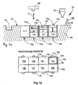
- FIG. 1A 12 shows a receiving device 20 for a total of eight drawers 10a-h arranged in two rows and four columns, as shown in FIG Figure 1B can be seen.
- Each slot 10a-h has an individually height-adjustable substrate plate segment 12a-f.
- Each substrate plate segment 12a-f is individually height-adjustable in a vertical direction 11 within its slot 10a-f.
- the vertical direction 11 for each of the substrate plate segments 12a-f is parallel to one another and perpendicular to the upper surface 13a-f of the substrate plate segments 12a-f, which is horizontal, ie perpendicular to the direction of gravity.
- the evaluations within the receiving device 20 are designed to receive a slot 10a-f in each case, in which a substrate plate segment 12a-f is arranged.
- substrate plate segments can also be inserted into the receiving device 20 which have a larger base area of the substrate plate 12a, for example a base area that is twice as large or four times as large as that in Fig. 1a, b represented substrate plate segments and occupy the corresponding two or four slots.
- a filling block 12g, 12h which does not represent a substrate plate segment and is not used for the manufacture of products, is inserted in the slots 10g and 10h.
- Each substrate plate segment 12a-f can be adjusted in height by means of an actuator 14a-f, which can be, for example, a linear actuator operated by an electric motor.
- the actuator 14a-f is part of the insert 10a-f.
- Each slot 10a-f is surrounded by a housing which is open at the top and has a rectangular, in particular square, cross-section and comprises four walls, as shown by the walls 15a-18a in the slot 10a by way of example.
- the substrate plate segment 12a moves within these walls and in so doing seals off at its lateral edge region with the walls in such a way that coating material which is applied to the substrate plate segment does not come between Substrate plate segment and the walls can pass through.
- the upper end edges of the walls are flush with a surface 21 of the receptacle 20 when the drawers 10a-e are inserted into the receptacle.
- an upper surface of the slide-in units 10g, h is flush with the surface 21 of the receiving device 20.
- a powder applicator 30 which includes a powder feeder 32 from which powder can be dispensed onto the surface 21 of the receptacle and which further includes a pusher 33 which extends along a direction of movement 31 reciprocally across the surface 21 and the substrate plate segments 12a-f or inserts 10a-h can move.
- the slide 33 distributes the powder discharged from the powder conveyor 32 and applies a layer of powder above the substrate plate segments 12a-f.
- the powder application device further comprises a collecting device 34 for excess powder.
- the slide 33 pushes the powder that could not be applied as a powder layer above the substrate plate segments into the collecting device 34 .
- the substrate plate segments 12a-f are set to different heights by means of their actuators 14a-f, i.e. the distance between the upper surface 13a-f of each substrate plate segment and the plane of the surface 21, along which the slide 33 moves and, as a squeegee, the Applying powder is different.
- each powder application process which is started by moving the slider 33 from the in Figure 1A shown right-hand position to a left-hand position in the area of the collecting trough 34 as seen from here, the layer applied during this powder application process above each substrate plate segment 12a-f is cured in predetermined areas by means of a radiation source, here a high-power laser 40.
- This selective curing is based on control data corresponding to the cross-section of a product in each layer applied.
- the cured areas are simultaneously bonded to corresponding underlying areas of the product that have been previously cured.
- the hardening process can take place in particular as selective laser sintering or selective laser melting.
- the beam of the high-power laser 40 is directed with beam steering means in such a way that it hits the predetermined areas of the previously applied layer and selectively cures these areas above all the previously coated substrate plate segments.
- the beam steering means are coupled in terms of signals to a control device.
- Manufacturing data for at least the products to be manufactured at the same time are stored in the control device.
- the production data include in particular position data which characterize the position of a respective product on the substrate plate and geometry data which characterize the geometry of the respective product.
- the geometric data is prepared in such a way that it contains the geometric data of individual cross-sections of the product.
- the respective position of such a cross section and the geometric data stored for this cross section corresponds to the position of the respectively applied material layer from which this product cross section is produced and the geometry of the product in this material layer. In the illustrated embodiment with products standing vertically on the plate, the geometric data therefore correspond to horizontal cross-sectional planes through this product.
- slide 33 moves from the left position to the in Figure 1A right position shown.
- the surface of the selectively hardened areas is ground using a grinding device arranged on the slider, in order to achieve a defined surface for the subsequent coating and hardening process and greater geometric precision of the generatively manufactured component.
- the substrate plate segments 12a-f are lowered by a predefined distance, which corresponds to the layer thickness of the layer subsequently applied.
- the surface of the previously applied layer and the selectively cured areas therein are no longer in alignment with the surface 21 along which the slide 33 moves with a lower squeegee edge, but below by the distance by which the substrate plate segment was lowered the plane of this surface 21.
- a metered quantity of powder is again discharged from the powder feeder 32 onto the surface 21 and, by moving the slide 33 to the left, this powder is applied as a layer above each lowered substrate plate segment.
- the process is repeated until a product is completed within the powder bed applied in layers in this way above a substrate plate segment. That's how it is Figure 1A as can be seen, the time of completion of one or more products above a substrate plate segment in the various drawers 10a-f differs; in the example shown, the product or products on the substrate plate segment 12e in drawer 10e is typically placed before the product or products on the substrate plate segment 12c in the Slot 10c can be completed if the products manufactured therein have approximately the same height.
- the drawer 10a is in the maximum raised position of the substrate plate segment 12a, which corresponds to the start of production.
- That tray can be removed from the cradle 20 and replaced with a new tray with the substrate plate in the uppermost position.
- the products in the removed tray can be detached from the substrate plate after uncured powder material has been removed.
- New products can be manufactured simultaneously on the newly deployed segment. A high level of productivity in the generative manufacturing of products is achieved as a result of the time-delayed but simultaneous construction of products in the device, which is possible in this way.
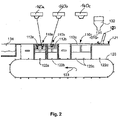
- FIG. 2 shows a second embodiment of the invention, in which several substrate plate segments 112a-c can be coupled as modules 110a-c on an endless conveyor belt 120.
- the actuator within each module is designed to adjust the height of each substrate plate segment 112a-c individually.
- the substrate plate segments 112a and 112b are designed as single segments, whereas the substrate plate segment 112c is designed as a double segment and extends along the conveyor belt 120 over twice the length.
- Each module 110a-c is, in turn, like the drawers according to FIG Figure 1A , B, are provided with side walls within which the substrate plate segments 112a-c can move vertically in an edge sealed manner.
- the peripheral walls terminate with their upper edges flush with a surface 121 onto which powder can in turn be discharged from a powder conveyor 132 .
- the surface 121 is horizontal, i.e.
- a powder bed of different height is set in each individual module 110a-c by gradually lowering the substrate plate segments 112a-c individually, thereby achieving a different production progress, i.e. the layer applied in one operation of the slide 133 is at a distance from the upper surface of the substrate plate segment 112c, which is different from the distance to the surface of the substrate plate segment 112b, which in turn is different from the surface of the substrate plate segment 112a.
- the layer applied in one operation of the slide 133 is at a distance from the upper surface of the substrate plate segment 112c, which is different from the distance to the surface of the substrate plate segment 112b, which in turn is different from the surface of the substrate plate segment 112a.
- the manufacturing progress in the modules 110a-c increases starting from the right in the conveying direction of the conveyor belt 120 to the left, as represented by the arrow 123.
- the conveyor belt is advanced far enough for this module to be removed, or the module is removed and the conveyor belt advanced by the corresponding length of the module.
- a new module can be inserted on the right-hand side adjacent to the illustrated position of the slide 133 and additive manufacturing can be started in this new module.
- the removed module can be further processed in a further production section; in particular, the unhardened powder material can be removed from this and the products manufactured therein can be removed from the substrate plate segment.
- the particular advantage here is that in the finished substrate plate segment, which was previously subjected to simultaneous production with the other substrate plate segments, it is now possible to remove the uncured powder and the finished products without removing the powder from other substrate plate segments must be or the manufacturing process must be stopped in the other substrate plate segments.
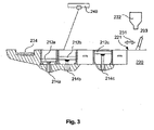
- FIG. 3 shows another embodiment of the invention.
- a plurality of substrate plate segments 212a-c are arranged next to one another and each surrounded by side walls in a sealed manner to the edge regions of each substrate plate segment.
- the side walls terminate with their upper edges flush with a surface 221 along which a slider 233 of a powder application device moves in a direction 231 with its lower edge serving as a squeegee edge.
- the pusher 233 applies a layer of powder above the substrate plate segments 212a-c in one working stroke and pushes excess powder into a collecting trough 234.
- a laser beam source 240 is also provided, which serves to selectively cure predetermined areas of the applied powder layer above each substrate plate segment.
- a controller for the manufacturing device is provided, which is designed in such a way that after each layer application process, predetermined areas above each Substrate plate segment are cured by the laser beam source 240, as previously described.
- a respective actuator 214a-c which is used to individually adjust the height of the substrate plate segments 212a-c and thereby individually change the distance between the upper surface of the respective substrate plate segment and the plane in which the squeegee edge of the slide 133 moves, not part of a Module, which is used in a recording device.
- these actuators 214a-c are integrated into the fixture 220 and the substrate plate segments 212a-c can be detachably coupled to the actuators 214a-c.
- a quasi-continuous production of products can thus be carried out in the same way by means of a generative production process such as SLS (Selective Laser Sintering) or SLM (Selective Laser Melting), with products being produced simultaneously in several substrate plate segments, which are in a different production stage for each substrate plate segment are.
- SLS Selective Laser Sintering
- SLM Selective Laser Melting
- FIGS Figures 1A - 3 show a fourth embodiment of the invention, which is characterized by certain features.
- the embodiment shown is based on the fundamentally similar principle as that in FIGS Figures 1A - 3 embodiments shown and has a substrate plate segment 312a, which can be arranged adjacent to other substrate plate segments (not shown) and can be individually adjusted in its height. It is to be understood that the 4 principle explained below on the in the Figures 1A - 3 illustrated embodiments can be applied.
- FIG. 4 shows a first dosing module 310a, which serves as a dosing platform and is filled with powder before the start of a manufacturing process.
- a height-adjustable base plate 312a is moved to the lowest position within the dosing module.
- a radiator field 380 is arranged above the dosing module 310a, which preheats the powder filled into the dosing module 310a.
- a squeegee 333 is horizontally displaceable along a direction 331 .
- a heating strip 335 is arranged in front of the doctor blade 333 in the direction of movement, which continuously heats the powder moved through the doctor blade or keeps it at the preheated temperature.
- the substrate plate segment 312b Adjacent to the dosing module 310a, the substrate plate segment 312b is arranged in a building module 310b.
- the substrate plate segment 312b is individually and independently of the base plate 312a vertically displaceable in the building module 310a.
- the construction module 310b lies between the dosing module 310a and a collection module 310c, which is used to collect excess powder that the squeegee 333 has pushed over the construction module 310b.
- a base plate 312c is also arranged in the collecting module 310c and can be vertically displaced individually and independently of the base plate 312a and the substrate plate segment 312b.
- the in 4 can also have several such construction modules substrate plate segments instead of the illustrated individual construction module 310b with substrate plate segment 312b. These several building modules would be arranged next to one another in the application direction 313 and the majority of the substrate plate segments would be placed overall between a dosing module 310a arranged at one end with respect to the displacement path 331 of the doctor blade 333 and a collecting module 310c arranged at the other end.
- a radiator array 380c is also arranged above the collection module 310c, which is used to keep the excess material collected in the collection module at a desired temperature.
- a heater 315b is built into the substrate plate segment 312b, which keeps the substrate plate segment and the powder bed arranged on it at a desired temperature.
- the embodiment shown is optimized overall in such a way that a desired, preheated powder state of the powder is achieved before the selective curing process by the radiator fields 380a, b, the heating band 335 and the heater 315b being provided.
- the manufacturing process that can be achieved in the illustrated embodiment consists of a sequence in which first the substrate plate segment 312b is lowered by a certain amount, which corresponds to the layer thickness to be applied, and the platform 312a of the dosing module 315a is raised by a certain amount, which results from the cross section of the platform and calculated based on the powder volume required for the subsequent application process.
- the preheated powder volume from the area of the dosing module is then pushed over the substrate plate segment 312b by horizontal movement of the squeegee 333 and a layer is thereby applied to the substrate plate segment 312b or possibly further substrate plate segments. Excess powder is fed into the collection module.
- a laser 340 is used to cut the powder layer in predetermined areas selectively cured and the cured areas bonded to previously cured areas in the underlying layer.
- the squeegee 333 then moves back, with the previously hardened areas being surface-ground by means of a grinding device, which is arranged in front of the squeegee in the direction of movement from left to right, in order to improve the geometric accuracy of the generatively manufactured product and the connection of the subsequent areas to be cured.
- a grinding device which is arranged in front of the squeegee in the direction of movement from left to right, in order to improve the geometric accuracy of the generatively manufactured product and the connection of the subsequent areas to be cured.
- the process begins again and is repeated until the product to be created is completed above substrate plate segment 312b or any other substrate plate segment arranged in a series of substrate plate segments.
- the laser beam of the laser beam source 340 is guided selectively over each layer in such a way that previously calculated areas of this layer, which correspond to the cross section of the products to be produced in the respective layer on all substrate plate segments, are selectively cured.
- the product can be separated from the substrate plate segment.
- the product can also be manufactured above a substrate plate segment and that several substrate plate segments can also be coated next to one another in different production stages with the single squeegee 333 and selectively cured with the single laser 340 .
- the powder collected in the collecting module 310c can be raised by raising the platform 312c and conveyed back from left to right into the dosing insert by moving the squeegee 333 accordingly, in order to start a new manufacturing process and use the powder again.
- the function of the dosing module and collection module can now be swapped over in the subsequent production process, so that the layer application process now takes place by moving the squeegee from left to right and the grinding process by a correspondingly reverse movement from right to left.
- the mobile unit consisting of the heating strip, doctor blade and grinding device should preferably be designed to be adjustable by 180° around a vertical axis.
- FIG 5 shows another embodiment of the invention.
- the manufacturing arrangement shown comprises a process chamber 1000, which has a first lock 1010 and a second lock 1020.
- Substrate plate segments are fed through the first lock 1010 and placed on a conveyor belt 1030 .
- the substrate plate segments are temporarily stored on this conveyor belt and can be preheated if necessary.
- the substrate plate segments can be placed on a construction platform 420b of a construction insert 410b by means of a robot arm 1040 in order to produce generative products thereon.
- the building block 410b is as before with respect to the embodiment according to FIG 4 explained with regard to the three modules 312a-c shown there, flanked by a dosing insert 410a and a receiving insert 410c and it is to be understood that several substrate plate segments can also be arranged next to each other between the dosing insert and the receiving insert in order to achieve quasi-continuous production in the previously explained way to perform.
- the substrate plate segment 412b can be moved into a lower position. In this lower position, the installation space above the substrate plate segment 412b is connected to a powder suction channel 490, which is embedded in the wall which delimits the installation space as a side wall. The uncured powder can then be sucked out of the area above the substrate plate segment 412b via this powder suction channel 490 .
- the powder suction channel 490 is also designed in such a way that the powder pushed into the collecting tray can also be sucked out through the suction channel 490, it being understood that this may or may not be provided as an optional further function.
- the construction platform can be moved vertically to the uppermost position and the substrate plate segment 412b can again be gripped by the robot arm 1040 and fed to a second conveyor belt 1050.
- the second conveyor belt 1050 is used to convey the substrate plate segment 412b together with the products arranged on it through a tempering oven 1060 in order to subject the products situated thereon to tempering and thereby produce the desired component properties. After the tempering has taken place, the substrate plate segment 412b can be discharged from the process chamber 1000 through the lock 1020 will.
- FIG. 6 shows a further aspect of the device according to the invention and of the method according to the invention.
- each of the substrate plate segments is individually adjustable in height by means of a respective lifting/lowering device 514a-d.
- Both the substrate plate segments in a row and the substrate plate segments in a column can be vertically displaced independently of one another, so that products can be produced generatively in different production stages on each of the substrate plate segments.
- Partition walls are to be provided between the respective substrate plate segments for the purpose of the individual construction of a powder bed above the respective substrate plate segment.
- these partitions are not part of the device, but that the partitions are continuously built up by selective hardening of the powder material in the edge area of the respective substrate plate segments and consequently grow vertically with the generatively manufactured product in the central area of the substrate plate segment.
- partition walls are provided as part of the production device and are arranged in such a way that their upper edge is flush with a plane in which a powder application blade moves.
- the embodiment has an endless conveyor belt 620 along which a plurality of substrate plate segments 612a-e are arranged in the conveying direction 621.
- the substrate plate segments 612a-e are placed such that their top surface lies in a common plane.
- a plurality of coating devices 630a-d are arranged above the substrate plate segments 612a-e.
- the individual coating devices 630a-d each comprise a squeegee 633a-d.
- the bottom edge of the squeegee 633a is spaced one layer from the surface of the substrate plate segments 612a-e.
- the lower edge of squeegee 633b is one layer further away from the surface of the substrate plate segments 612a-e than the previous squeegee 633a, and in the same way the lower edges of the squeegee 633c, d are correspondingly one layer thickness more from the surface of the substrate plate segments compared to the preceding, adjacent squeegee raised.
- the in 7 illustrated embodiment is to be understood in such a way that a large number of individual coating devices a, b, c, d . . . arranged next to one another are provided in such a vertically staggered height arrangement.
- each two layer application devices 633a, b, c . . . there is an area in which the applied layer can be selectively cured by means of a laser 640a, b, c, d.
- a corresponding laser is assigned to each individual coating device.
- the conveyor belt 620 is moved continuously or discontinuously during production in such a way that the upper run moves in the in 7 shown constellation moved from right to left. As a result, a material bed is applied by successive layers above the substrate plate segments 612a, b, c . . . In the same way, the overall height of the products produced additively on the respective substrate plate segments increases.
- the conveyor belt 620 can also be reciprocally moved back and forth several times during a manufacturing process and the multiple powder application devices or the conveyor belt can be displaced vertically in order to apply a number of M x N powder layers during a manufacturing process using a number of N powder application devices, where M corresponds to the number of reciprocating movements of the conveyor belt.
- the N powder applicators are raised or the conveyor belt is lowered by an amount corresponding to N times the layer thickness, in order to achieve that the rightmost and consequently most lowest-lying powder application device in the subsequent application process applies its layer to the layer previously applied by the leftmost and consequently highest arranged powder application device.
- the uncured powder material 590 is suctioned off in the conveying direction to the left of the conveyor belt 520 from the area above a substrate plate segment on which the finished products lie. It is to be understood that such a powder suction takes place only above the substrate plate segment lying furthest to the left, whereas the substrate plate segment lying to the right thereof due to the products that are usually not yet finished there, it is not yet extracted. This can be achieved by means of partitions constructed in parallel between the substrate plate segments.
- the products produced on the substrate plate segment can be separated from it. If necessary, after this separation process, the surfaces of the substrate plate segment can be prepared flat again by means of a device for surface smoothing arranged to the left of the suction device, in particular a milling or grinding station or a device for laser smoothing, in order to subsequently feed the substrate plate segment into a new additive manufacturing process.
- a device for surface smoothing arranged to the left of the suction device, in particular a milling or grinding station or a device for laser smoothing, in order to subsequently feed the substrate plate segment into a new additive manufacturing process.
- the multiple radiation sources can be provided by individual laser sources, respectively, or by one or more laser sources whose beam can be split and consequently directed to a corresponding number of locations. It should also be understood here that the divided beam and the multiple beam paths generated from it can also be guided individually over the respective layers by appropriate radiation guide means in order to selectively cure each layer individually.
- the layer application process for all substrate plate segments takes place in a common first operation, followed by a selective curing process in a second operation. With a corresponding number of individual coating devices, this can take place with continuous movement of the conveyor belt or—with reciprocal movement of the conveyor belt—in a quasi-continuous process.
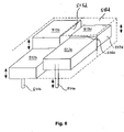
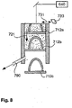
- a further embodiment of the invention can be seen.
- a plurality of substrate plate segments 712a, b are arranged one above the other and the installation space above the respective substrate plate segments is limited by common side walls 715-718.
- the substrate plate segments 712a, b Using a layer application device, layers are applied iteratively in the installation space provided above the uppermost substrate plate segment 712b and selectively cured using a laser beam source. It should be understood here that the layer application process can be carried out in the same way as explained above using a squeegee. This squeegee moves at the in 8 shown embodiment in a horizontal plane, ie perpendicular to the conveying direction of the substrate plate segments 712a, b.
- a new substrate plate segment can be placed on top of it, being coupled in a corresponding manner to a conveyor device for the vertical movement.
- the substrate plate segments with finished products built on them can be removed in a production section arranged below the layer application device and the construction space in which generative production is carried out, in that the powder is sucked off and the products are separated from the substrate plate segment.
- a duct suction can be used, as with respect figure 5 was explained in order to subsequently promote the products in an area that is not limited by side walls and thereby allow the removal of the products or the entire substrate plate segment from the vertical conveyor.
Landscapes
- Engineering & Computer Science (AREA)
- Health & Medical Sciences (AREA)
- Manufacturing & Machinery (AREA)
- Physics & Mathematics (AREA)
- Materials Engineering (AREA)
- Chemical & Material Sciences (AREA)
- Optics & Photonics (AREA)
- Oral & Maxillofacial Surgery (AREA)
- Dentistry (AREA)
- Epidemiology (AREA)
- Life Sciences & Earth Sciences (AREA)
- Animal Behavior & Ethology (AREA)
- General Health & Medical Sciences (AREA)
- Public Health (AREA)
- Veterinary Medicine (AREA)
- Mechanical Engineering (AREA)
- Plasma & Fusion (AREA)
Claims (15)
- Procédé de fabrication de produits présentant une géométrie individuelle, en particulier, de prothèse dentaire ou de pièces auxiliaires de dentisterie, comprenant les étapes de :- fabrication de plusieurs produits sur la surface d'une plaque substrat au moyen d'un durcissement sélectif, en particulier par frittage sélectif ou fusion sélective,- dans lequel le matériau est appliqué en couches successives,- après chaque application de couche, une ou plusieurs zones prédéterminées sont durcies sélectivement au moyen d'un rayonnement riche en énergie et sont liées à une ou plusieurs zones de la couche sous-jacente,- dans lequel les zones prédéterminées sont prédéterminées sur la base d'une géométrie transversale du produit dans la couche respective,- mise à disposition d'une plaque substrat qui est subdivisée en un premier segment de plaque substrat (12, 112, 212, 312, 412, 512, 612, 712) et au moins un autre segment de plaque substrat (12, 112, 212, 312, 412, 512, 612, 712),- fabrication d'un premier produit sur le premier segment de plaque substrat (12, 112, 212, 312, 412, 512, 612, 712) par applications successives de couches de matériau sur le premier segment de plaque substrat (12, 112, 212, 312, 412, 512, 612, 712) et durcissement sélectif des zones prédéterminées de chaque couche de matériau appliquée après son application,- fabrication d'au moins un autre produit sur l'au moins un autre segment de plaque substrat par applications successives de couches de matériau sur l'autre segment de plaque substrat (12, 112, 212, 312, 412, 512, 612, 712) et durcissement sélectif de zones prédéterminées de chaque couche de matériau appliquée après son application, caractérisé en ce que le premier et chaque autre segment de plaque substrat (12, 112, 212, 312, 412, 512, 612, 712) sont liés les uns aux autres de façon détachable ou à un support de base et, pendant le processus de fabrication, sont soulevés et abaissés dans une direction verticale au moyen d'un dispositif de levage et les mouvements de soulèvement et d'abaissement des segments de plaque substrat (12, 112, 212, 312, 412, 512, 612, 712) sont indépendants l'un de l'autre,et que les segments de plaque substrat sont fixés à une bande de transport sans fin ou sont liés entre eux de telle manière qu'ils forment une bande de transport sans fin sous la forme d'une chaîne à maillons.
- Procédé de fabrication de produits présentant une géométrie individuelle, en particulier, de prothèse dentaire ou de pièces auxiliaires de dentisterie, comprenant les étapes de :- fabrication de plusieurs produits sur la surface d'une plaque substrat au moyen d'un durcissement sélectif, en particulier par frittage sélectif ou fusion sélective,- dans lequel le matériau est appliqué en couches successives,- après chaque application de couche, une ou plusieurs zones prédéterminées sont durcies sélectivement au moyen d'un rayonnement riche en énergie et sont liées à une ou plusieurs zones de la couche sous-jacente,- dans lequel les zones prédéterminées sont prédéterminées sur la base d'une géométrie transversale du produit dans la couche respective,- mise à disposition d'une plaque substrat qui est subdivisée en un premier segment de plaque substrat (12, 112, 212, 312, 412, 512, 612, 712) et au moins un autre segment de plaque substrat (12, 112, 212, 312, 412, 512, 612, 712),- fabrication d'un premier produit sur le premier segment de plaque substrat (12, 112, 212, 312, 412, 512, 612, 712) par applications successives de couches de matériau sur le premier segment de plaque substrat (12, 112, 212, 312, 412, 512, 612, 712) et durcissement sélectif des zones prédéterminées de chaque couche de matériau appliquée après son application,- fabrication d'au moins un autre produit sur l'au moins un autre segment de plaque substrat (12, 112, 212, 312, 412, 512, 612, 712) par applications successives de couches de matériau sur l'autre segment de plaque substrat (12, 112, 212, 312, 412, 512, 612, 712) et durcissement sélectif de zones prédéterminées de chaque couche de matériau appliquée après son application,
caractérisé en ce que- dans une première étape de procédé, une couche de matériau est appliquée sur au moins deux, de préférence plusieurs segments de plaque substrat (12, 112, 212, 312, 412, 512, 612, 712) qui sont liés les uns des autres de manière détachable, de telle sorte que sur le premier segment de plaque substrat (12, 112, 212, 312, 412, 512, 612, 712), une première partie de couche et sur chaque autre segment de plaque substrat (12, 112, 212, 312, 412, 512, 612, 712), une autre partie de couche qui correspond soit appliquée,- dans une deuxième étape de procédé, la couche de matériau est durcie sélectivement, et- la distance maximale entre le premier segment de plaque substrat (12, 112, 212, 312, 412, 512, 612, 712) et la partie de couche appliquée sur celui-ci pour la fabrication du premier produit en au moins un, de préférence plusieurs, en particulier tous les stades de procédé se distingue de la distance maximale entre l'autre segment de plaque substrat (12, 112, 212, 312, 412, 512, 612, 712) et la partie de couche appliquée sur celui-ci pour la fabrication de l'autre produit,- dans lequel plusieurs segments de plaque substrat (12, 112, 212, 312, 412, 512, 612, 712) sont revêtus d'un matériau dans un cycle d'opération avec un seul dispositif d'application de matériau (33, 133, 233, 333, 633, 733). - Procédé selon la revendication 1 ou 2,
caractérisé en ce que les segments de plaque substrat (12, 112, 212, 312, 412, 512, 612, 712) sont mis à disposition côté à côté de telle sorte qu'entre les segments de plaques substrat (12, 112, 212, 312, 412, 512, 612, 712), aucun matériau ne puisse passer. - Procédé selon la revendication 2,
caractérisé en ce que les segments de plaque substrat (12, 112, 212, 312, 412, 512, 612, 712) sont conçus comme des segments d'un dispositif de transport sans fin (120, 620). - Procédé selon l'une des revendications précédentes,
caractérisé en ce que le matériau dans une première étape de production est appliqué dans un procédé quasi-continu sur la plaque substrat et des zones prédéterminées sélectivement d'une couche appliquée respective sont durcies et dans une deuxième étape de production des produits durcis complètement sont retirés de façon quasi-continue. - Procédé selon l'une des revendications précédentes,
caractérisé en ce que, entre les segments de plaque substrat (12, 112, 212, 312, 412, 512, 612, 712), est mise à disposition une paroi de séparation qui sépare l'espace de montage se trouvant au dessus de chaque segment de plaque substrat de l'espace de montage se trouvant au dessus d'un segment de plaque de substrat voisin et la paroi de séparation est fabriquée de préférence par durcissement du matériau appliqué pendant le processus de fabrication du produit. - Procédé selon l'une des revendications précédentes,
caractérisé en ce qu'avant chaque application de matériau, les zones durcies de la couche appliquée auparavant sont polies superficiellement. - Procédé selon l'une des revendications précédentes,
caractérisé en ce que, pour le durcissement du premier et de l'au moins un autre produit, en particulier de tous les autres produits, une seule source de rayonnement (40, 140, 240, 340, 640), en particulier un seul cycle de rayonnement d'une seule source de rayonnement (40, 140, 240, 340, 640) est utilisé. - Procédé selon l'une des revendications 2-8 précédentes,
caractérisé en ce que chaque segment de plaque substrat (12, 112, 212, 312, 412, 512, 612, 712) est soulevé et abaissé dans une direction verticale pendant le processus de fabrication au moyen d'un dispositif de levage et les mouvements de soulèvement et d'abaissement des segments de plaque substrat (12, 112, 212, 312, 412, 512, 612, 712) sont indépendants l'un de l'autre. - Procédé selon la revendication 1,
caractérisé en ce que plusieurs segments de plaque substrat (12, 112, 212, 312, 412, 512, 612, 712) sont revêtus d'un matériau dans un cycle d'opération avec un seul dispositif d'application de matériau (33, 133, 233, 333, 633, 733). - Dispositif de fabrication de produits présentant une géométrie individuelle, comprenant :- une plaque substrat- un dispositif d'application de matériau (33, 133, 233, 333, 633, 733) pour appliquer un matériau sur la plaque de substrat,- une source de rayonnement (40, 140, 240, 340, 640) pour un rayonnement hautement énergétique,- un moyen de guidage de rayon pour guider le rayon sur des zones prédéterminées d'une couche de matériau appliquée sur la plaque substrat,- la plaque substrat est subdivisée en plusieurs segments de plaque substrat (12, 112, 212, 312, 412, 512, 612, 712),caractérisé en ce que le premier et chaque autre segment de plaque substrat (12, 112, 212, 312, 412, 512, 612, 712) sont liés les uns aux autres de façon détachable ou à un support de base et pendant le processus de fabrication sont soulevables et abaissables dans une direction verticale au moyen d'un dispositif de levage et les mouvements de soulèvement et d'abaissement des segments de plaque substrat (12, 112, 212, 312, 412, 512, 612, 712) sont indépendants l'un de l'autre,
et que les segments de plaque substrat sont fixés à une bande de transport sans fin ou sont liés entre eux de manière à former une bande de transport sans fin sous la forme d'une chaîne à maillons. - Dispositif de fabrication de produits présentant une géométrie individuelle, comprenant :- une plaque substrat- un dispositif d'application de matériau (33, 133, 233, 333, 633, 733) pour appliquer un matériau sur la plaque de substrat,- une source de rayonnement (40, 140, 240, 340, 640) pour un rayonnement hautement énergétique,- un moyen de guidage de rayon pour guider le rayon sur des zones prédéterminées d'une couche de matériau appliquée sur la plaque substrat,- la plaque substrat est subdivisée en plusieurs segments de plaque substrat (12, 112, 212, 312, 412, 512, 612, 712),
caractérisé en ce que- les segments de plaque substrat (12, 112, 212, 312, 412, 512, 612, 712) qui sont liés les uns aux autres de façon détachable, et que les segments de plaque substrat et le dispositif d'apport de matériau peuvent être déplacés individuellement les uns des autres, au moyen d'un ou plusieurs actionneurs de telle sorte que la distance entre le plan de la surface d'un premier segment de plaque substrat (12, 112, 212, 312, 412, 512, 612, 712) et d'une partie de couche de la couche de matériau appliquée sur celui-ci pour la fabrication d'un premier produit se distingue de la distance entre le plan de la surface d'un autre segment de plaque substrat (12, 112, 212, 312, 412, 512, 612, 712) et d'une partie de couche de la couche de matériau appliquée sur celui-ci pour la fabrication de l'autre produit,et que le dispositif d'application de matériau (33, 133, 233, 333, 633, 733) pour l'application simultanée d'une couche de matériau au dessus d'un nombre de plusieurs segments de plaque substrat (12, 112, 212, 312, 412, 512, 612, 712) est formé en un cycle de travail. - Dispositif selon l'une des revendications précédentes 11 à 12,
caractérisé par un dispositif d'élimination de matériau (490, 790), en particulier un système d'aspiration de matériau, dans lequel le dispositif d'élimination de matériau (490, 790) est formé, pour éliminer un matériau non durci d'une zone environnante d'un produit fabriqué et est conçu de telle sorte qu'il puisse éliminer le matériau sur un premier segment de plaque substrat et puisse ainsi laisser le matériau sur un autre segment de plaque substrat voisin (12, 112, 212, 312, 412, 512, 612, 712). - Dispositif selon l'une des revendications 11-13 précédentes,
caractérisé en ce que les segments de plaque substrat (12, 112, 212, 312, 412, 512, 612, 712) sont disposés sur une bande de transport sans fin (120, 620) qui avance partiellement ou complètement dans une chambre de traitement qui est fermée hermétiquement de l'environnement de telle sorte qu'une atmosphère contrôlée, de préférence inerte puisse y être ajustée. - Dispositif selon l'une des revendications 11-14 précédentes,
caractérisé par une commande pour commander le moyen de guidage de rayon du rayon hautement énergétique qui est formé, pour commander le moyen de guidage de rayon de telle sorte que la paroi de séparation soit fabriquée pendant le processus de fabrication du produit par durcissement du matériau appliqué.
Priority Applications (3)
| Application Number | Priority Date | Filing Date | Title |
|---|---|---|---|
| EP09168566.9A EP2289652B2 (fr) | 2009-08-25 | 2009-08-25 | Dispositif et procédé de fabrication générative |
| US13/392,442 US9067360B2 (en) | 2009-08-25 | 2010-08-25 | Device and method for generative production |
| PCT/EP2010/062371 WO2011023714A1 (fr) | 2009-08-25 | 2010-08-25 | Dispositif et procédé pour la fabrication génératrice |
Applications Claiming Priority (1)
| Application Number | Priority Date | Filing Date | Title |
|---|---|---|---|
| EP09168566.9A EP2289652B2 (fr) | 2009-08-25 | 2009-08-25 | Dispositif et procédé de fabrication générative |
Publications (3)
| Publication Number | Publication Date |
|---|---|
| EP2289652A1 EP2289652A1 (fr) | 2011-03-02 |
| EP2289652B1 EP2289652B1 (fr) | 2014-04-16 |
| EP2289652B2 true EP2289652B2 (fr) | 2022-09-28 |
Family
ID=42027867
Family Applications (1)
| Application Number | Title | Priority Date | Filing Date |
|---|---|---|---|
| EP09168566.9A Active EP2289652B2 (fr) | 2009-08-25 | 2009-08-25 | Dispositif et procédé de fabrication générative |
Country Status (3)
| Country | Link |
|---|---|
| US (1) | US9067360B2 (fr) |
| EP (1) | EP2289652B2 (fr) |
| WO (1) | WO2011023714A1 (fr) |
Families Citing this family (138)
| Publication number | Priority date | Publication date | Assignee | Title |
|---|---|---|---|---|
| US8992816B2 (en) | 2008-01-03 | 2015-03-31 | Arcam Ab | Method and apparatus for producing three-dimensional objects |
| US9399321B2 (en) | 2009-07-15 | 2016-07-26 | Arcam Ab | Method and apparatus for producing three-dimensional objects |
| EP2289652B2 (fr) | 2009-08-25 | 2022-09-28 | BEGO Medical GmbH | Dispositif et procédé de fabrication générative |
| DE202011003443U1 (de) | 2011-03-02 | 2011-12-23 | Bego Medical Gmbh | Vorrichtung zur generativen Herstellung dreidimensionaler Bauteile |
| DE102011005929A1 (de) * | 2011-03-23 | 2012-09-27 | Bayerische Motoren Werke Aktiengesellschaft | Vorrichtung und Verfahren zum Herstellen eines Bauteils in Schichtbauweise |
| DE102011075748B4 (de) * | 2011-05-12 | 2024-04-25 | Realizer Gmbh | Vorrichtung zur aufeinander folgenden Herstellung von Formkörpern durch schichtweises Aufbauen aus Werkstoffpulver |
| DE102011117005B4 (de) * | 2011-10-25 | 2016-05-04 | Fraunhofer-Gesellschaft zur Förderung der angewandten Forschung e.V. | Verfahren zur Herstellung eines keramischen Formkörpers |
| DE102011119839B4 (de) * | 2011-12-01 | 2019-11-28 | Kulzer Gmbh | Herstellen von Suprakonstruktionen auf einer SLM-Anlage mit anschließender Fräsbearbeitung der Anschlussgeometrie |
| WO2013098135A1 (fr) | 2011-12-28 | 2013-07-04 | Arcam Ab | Procédé et appareil pour fabriquer des articles tridimensionnels poreux |
| WO2013098054A1 (fr) | 2011-12-28 | 2013-07-04 | Arcam Ab | Procédé et appareil de détection de défauts pour une fabrication de forme libre |
| DE102012012344B4 (de) * | 2012-03-21 | 2018-05-17 | Fraunhofer-Gesellschaft zur Förderung der angewandten Forschung e.V. | Verfahren und Vorrichtung zur Herstellung von Werkstücken durch Strahlschmelzen pulverförmigen Materials |
| US10383713B2 (en) | 2012-05-10 | 2019-08-20 | Renishaw Plc | Method of manufacturing an article |
| CN104363856B (zh) | 2012-05-10 | 2016-11-16 | 瑞尼斯豪公司 | 制造物品的方法 |
| DE102012011217B4 (de) * | 2012-06-06 | 2025-08-21 | Concept Laser Gmbh | Vorrichtung zur Herstellung von dreidimensionalen Bauteilen |
| US20140077422A1 (en) * | 2012-09-19 | 2014-03-20 | Pratt & Whitney Rocketdyne, Inc. | Reduced build mass additive manufacturing chamber |
| EP2727709A1 (fr) | 2012-10-31 | 2014-05-07 | Nederlandse Organisatie voor toegepast -natuurwetenschappelijk onderzoek TNO | Procédé et appareil pour fabriquer des produits tangibles par fabrication par couches |
| US10987868B2 (en) | 2012-10-31 | 2021-04-27 | Nederlandse Organisatie Voor Toegepast-Natuurwetenschappelijk Onderzoek Tno | Production line for making tangible products by layerwise manufacturing |
| DE102012223239A1 (de) * | 2012-12-14 | 2014-06-18 | BEGO Bremer Goldschlägerei Wilh. Herbst GmbH & Co. KG | Edelmetall-Dentallegierung für den SLM-Prozess |
| GB2522388B (en) | 2012-12-17 | 2017-08-23 | Arcam Ab | Additive manufacturing method and apparatus |
| US9550207B2 (en) | 2013-04-18 | 2017-01-24 | Arcam Ab | Method and apparatus for additive manufacturing |
| DE102013218893A1 (de) * | 2013-09-20 | 2015-03-26 | Bayerische Motoren Werke Aktiengesellschaft | Strahlschmelzanlage für die Herstellung von Fahrzeugbauteilen |
| US9676032B2 (en) | 2013-09-20 | 2017-06-13 | Arcam Ab | Method for additive manufacturing |
| DE102013223411A1 (de) | 2013-11-15 | 2015-05-21 | Eos Gmbh Electro Optical Systems | Vorrichtung zum schichtweisen Herstellen eines dreidimensionalen Objekts |
| US10434572B2 (en) | 2013-12-19 | 2019-10-08 | Arcam Ab | Method for additive manufacturing |
| US9802253B2 (en) | 2013-12-16 | 2017-10-31 | Arcam Ab | Additive manufacturing of three-dimensional articles |
| US10130993B2 (en) | 2013-12-18 | 2018-11-20 | Arcam Ab | Additive manufacturing of three-dimensional articles |
| US9789563B2 (en) | 2013-12-20 | 2017-10-17 | Arcam Ab | Method for additive manufacturing |
| DE102013021891A1 (de) * | 2013-12-23 | 2015-06-25 | Voxeljet Ag | Vorrichtung und Verfahren mit beschleunigter Verfahrensführung für 3D-Druckverfahren |
| US9789541B2 (en) | 2014-03-07 | 2017-10-17 | Arcam Ab | Method for additive manufacturing of three-dimensional articles |
| US20150283613A1 (en) | 2014-04-02 | 2015-10-08 | Arcam Ab | Method for fusing a workpiece |
| TWI678274B (zh) | 2014-04-30 | 2019-12-01 | 荷蘭商荷蘭Tno自然科學組織公司 | 用以藉由分層製造技術製作有形產品之方法及生產線 |
| DE102014010931A1 (de) * | 2014-07-28 | 2016-01-28 | Cl Schutzrechtsverwaltungs Gmbh | Vorrichtung zur generativen Herstellung dreidimensionaler Objekte |
| US9347770B2 (en) | 2014-08-20 | 2016-05-24 | Arcam Ab | Energy beam size verification |
| DE102014016718A1 (de) * | 2014-11-13 | 2016-05-19 | Cl Schutzrechtsverwaltungs Gmbh | Produktionsanlage zur simultanen, generativen Herstellung von mehreren Bauteilen |
| GB201420601D0 (en) * | 2014-11-19 | 2015-01-07 | Digital Metal Ab | Method and apparatus for manufacturing a series of objects |
| GB201420717D0 (en) | 2014-11-21 | 2015-01-07 | Renishaw Plc | Additive manufacturing apparatus and methods |
| US10786865B2 (en) | 2014-12-15 | 2020-09-29 | Arcam Ab | Method for additive manufacturing |
| DE102015200634A1 (de) * | 2015-01-16 | 2016-07-21 | Siemens Aktiengesellschaft | Sandwichbauweise und Vorgehensweise bei einer AM-Anlage |
| DE102015200635A1 (de) * | 2015-01-16 | 2016-07-21 | Siemens Aktiengesellschaft | Mehrfach-AM-Anlage |
| US9721755B2 (en) | 2015-01-21 | 2017-08-01 | Arcam Ab | Method and device for characterizing an electron beam |
| DE102015001480A1 (de) * | 2015-02-09 | 2016-08-11 | Werkzeugbau Siegfried Hofmann Gmbh | Verfahren zum Herstellen eines dreidimensionalen Objekts durch aufeinander folgendes Verfestigen von Schichten |
| US9925723B2 (en) * | 2015-03-27 | 2018-03-27 | Delavan Inc. | Additive manufacturing systems and methods |
| DE102016204462A1 (de) | 2015-03-31 | 2016-10-06 | Krause DiMaTec GmbH | Verfahren zum Herstellen eines Bauteils sowie Trägerplatte zum Tragen von additiv zu fertigenden Bauteilen, ausgelegt zum Durchführen eines solchen Verfahrens |
| DE102015207158A1 (de) * | 2015-04-20 | 2016-10-20 | Eos Gmbh Electro Optical Systems | Verfahren und Vorrichtung zum Herstellen eines dreidimensionalen Objekts |
| US11014161B2 (en) | 2015-04-21 | 2021-05-25 | Arcam Ab | Method for additive manufacturing |
| US10315408B2 (en) * | 2015-04-28 | 2019-06-11 | General Electric Company | Additive manufacturing apparatus and method |
| DE102015109525A1 (de) * | 2015-06-15 | 2016-12-15 | Cl Schutzrechtsverwaltungs Gmbh | Vorrichtung zum Herstellen von dreidimensionalen Objekten sowie ein zugehöriges Verfahren |
| DE102015212420A1 (de) * | 2015-07-02 | 2017-01-05 | Siemens Aktiengesellschaft | Vorrichtung zur additiven Fertigung eines Bauteils |
| US10807187B2 (en) | 2015-09-24 | 2020-10-20 | Arcam Ab | X-ray calibration standard object |
| DE102015116282A1 (de) * | 2015-09-25 | 2017-03-30 | Cl Schutzrechtsverwaltungs Gmbh | Anlage zur Herstellung von dreidimensionalen Objekten |
| WO2017051029A1 (fr) * | 2015-09-25 | 2017-03-30 | Addifab Aps | Dispositif et système de fabrication additive, plate-forme de construction modulaire et unité de plate-forme de construction |
| US10583483B2 (en) | 2015-10-15 | 2020-03-10 | Arcam Ab | Method and apparatus for producing a three-dimensional article |
| US10525531B2 (en) | 2015-11-17 | 2020-01-07 | Arcam Ab | Additive manufacturing of three-dimensional articles |
| US10610930B2 (en) | 2015-11-18 | 2020-04-07 | Arcam Ab | Additive manufacturing of three-dimensional articles |
| DE102015225652A1 (de) * | 2015-12-17 | 2017-06-22 | Siemens Aktiengesellschaft | Verfahren zur additiven Herstellung, Bauteil und Einrichtung zur additiven Herstellung |
| DE102016201369A1 (de) * | 2016-01-29 | 2017-08-03 | Siemens Aktiengesellschaft | Vorrichtung, Anlage und Verfahren zur additiven Herstellung eines Bauteils |
| US11247274B2 (en) | 2016-03-11 | 2022-02-15 | Arcam Ab | Method and apparatus for forming a three-dimensional article |
| DE102016206355A1 (de) * | 2016-04-15 | 2017-10-19 | Bayerische Motoren Werke Aktiengesellschaft | Huberzeugungseinrichtung, Fertigungssystem sowie additives Fertigungsverfahren |
| DE102016207896A1 (de) * | 2016-05-09 | 2017-11-09 | Siemens Aktiengesellschaft | Vorrichtung mit Schleuse für die additive Herstellung |
| US10549348B2 (en) | 2016-05-24 | 2020-02-04 | Arcam Ab | Method for additive manufacturing |
| US11325191B2 (en) | 2016-05-24 | 2022-05-10 | Arcam Ab | Method for additive manufacturing |
| DE102016109941A1 (de) * | 2016-05-30 | 2017-11-30 | Cl Schutzrechtsverwaltungs Gmbh | Verfahren und Anlage zur additiven Herstellung eines Objekts |
| US10525547B2 (en) | 2016-06-01 | 2020-01-07 | Arcam Ab | Additive manufacturing of three-dimensional articles |
| DE102016212573A1 (de) * | 2016-07-11 | 2018-01-11 | Fraunhofer-Gesellschaft zur Förderung der angewandten Forschung e.V. | Verfahren zur Herstellung von dreidimensionalen Bauteilen mit einem pulverbettbasierten Strahlschmelzverfahren |
| DE102016212571A1 (de) * | 2016-07-11 | 2018-01-11 | Fraunhofer-Gesellschaft zur Förderung der angewandten Forschung e.V. | Vorrichtung und Verfahren zur Herstellung von dreidimensionalen Bauteilen mit einem pulverbettbasierten Strahlschmelzverfahren |
| US10821717B2 (en) | 2016-07-22 | 2020-11-03 | General Electric Company | Layer orientation control for pixel-based additive manufacturing |
| DE102016114057A1 (de) * | 2016-07-29 | 2018-02-01 | Cl Schutzrechtsverwaltungs Gmbh | Baukammer für eine Vorrichtung zur additiven Herstellung dreidimensionaler Objekte |
| EP3281727B8 (fr) * | 2016-08-10 | 2023-11-22 | Nikon SLM Solutions AG | Appareil de production de pièces tridimensionnelles comprenant une pluralité de dispositifs d'application de poudre |
| US10792757B2 (en) | 2016-10-25 | 2020-10-06 | Arcam Ab | Method and apparatus for additive manufacturing |
| PT109710B (pt) * | 2016-10-28 | 2024-02-28 | Inst Superior Tecnico | Sistema de fabrico aditivo modular |
| DE102016121773A1 (de) * | 2016-11-14 | 2018-05-17 | Cl Schutzrechtsverwaltungs Gmbh | Auspackeinrichtung zum Auspacken eines additiv hergestellten dreidimensionalen Objekts aus dem dieses umgebenden Baumaterial |
| US10987752B2 (en) | 2016-12-21 | 2021-04-27 | Arcam Ab | Additive manufacturing of three-dimensional articles |
| US11167454B2 (en) * | 2017-01-13 | 2021-11-09 | General Electric Company | Method and apparatus for continuously refreshing a recoater blade for additive manufacturing |
| DE102017201084A1 (de) * | 2017-01-24 | 2018-07-26 | Siemens Aktiengesellschaft | Verfahren zur additiven Herstellung und Beschichtungsvorrichtung |
| EP3351321A1 (fr) * | 2017-01-24 | 2018-07-25 | Siemens Aktiengesellschaft | Dispositif et procédé de fabrication additive d'au moins un corps de moule |
| WO2018194567A1 (fr) * | 2017-04-18 | 2018-10-25 | Hewlett-Packard Development Company, L.P. | Appareil ayant une chambre mobile |
| EP3612371A4 (fr) * | 2017-04-20 | 2020-11-25 | Hewlett-Packard Development Company, L.P. | Imprimante 3d et module de construction |
| US11007713B2 (en) * | 2017-04-26 | 2021-05-18 | GM Global Technology Operations LLC | High throughput additive manufacturing system |
| US11059123B2 (en) | 2017-04-28 | 2021-07-13 | Arcam Ab | Additive manufacturing of three-dimensional articles |
| US11014302B2 (en) * | 2017-05-11 | 2021-05-25 | Seurat Technologies, Inc. | Switchyard beam routing of patterned light for additive manufacturing |
| US11292062B2 (en) | 2017-05-30 | 2022-04-05 | Arcam Ab | Method and device for producing three-dimensional objects |
| DE102017118065A1 (de) * | 2017-08-09 | 2019-02-14 | Karlsruher Institut für Technologie | Generative Fertigungsanlage und Verfahren zur Herstellung von Bauteilen mittels dieser generativen Fertigungsanlage |
| CN107415234B (zh) * | 2017-08-16 | 2019-07-19 | 中国矿业大学 | 一种垂直送料的三维打印机 |
| US11185926B2 (en) | 2017-09-29 | 2021-11-30 | Arcam Ab | Method and apparatus for additive manufacturing |
| US11273495B2 (en) | 2017-10-02 | 2022-03-15 | General Electric Company | Modified frame and recoating system |
| DE102017219090A1 (de) * | 2017-10-25 | 2019-04-25 | Volkswagen Aktiengesellschaft | Anlage zur kontinuierlichen generativen Fertigung von Werkstücken |
| US10529070B2 (en) | 2017-11-10 | 2020-01-07 | Arcam Ab | Method and apparatus for detecting electron beam source filament wear |
| TWI640418B (zh) * | 2017-11-15 | 2018-11-11 | 國家中山科學研究院 | 積層製造加工槽及其積層製造設備 |
| US11072117B2 (en) | 2017-11-27 | 2021-07-27 | Arcam Ab | Platform device |
| US10821721B2 (en) | 2017-11-27 | 2020-11-03 | Arcam Ab | Method for analysing a build layer |
| US12350754B2 (en) | 2017-12-22 | 2025-07-08 | Arcam Ab | Electron beam source and the use of the same |
| US11517975B2 (en) | 2017-12-22 | 2022-12-06 | Arcam Ab | Enhanced electron beam generation |
| WO2019155460A1 (fr) * | 2018-02-06 | 2019-08-15 | Assembrix Ltd. | Impression tridimensionnelle à étagères multiples |
| US11267051B2 (en) | 2018-02-27 | 2022-03-08 | Arcam Ab | Build tank for an additive manufacturing apparatus |
| US10800101B2 (en) | 2018-02-27 | 2020-10-13 | Arcam Ab | Compact build tank for an additive manufacturing apparatus |
| US11400519B2 (en) | 2018-03-29 | 2022-08-02 | Arcam Ab | Method and device for distributing powder material |
| DE102018210363A1 (de) * | 2018-06-26 | 2020-01-02 | Bayerische Motoren Werke Aktiengesellschaft | Verfahren zum Betrieb einer Anlage zur additiven Herstellung von dreidimensionalen Bauteilen |
| CN110757790A (zh) * | 2018-07-27 | 2020-02-07 | 三纬国际立体列印科技股份有限公司 | 3d激光打印装置及其操作方法 |
| DE102018128757A1 (de) | 2018-11-15 | 2020-05-20 | Gebr. Becker Gmbh | Verfahren und Vorrichtung zum Betrieb einer Metall-Druckeinrichtung |
| DE102018129024A1 (de) | 2018-11-19 | 2020-05-20 | AMCM GmbH | Verfahren zur additiven Fertigung und System |
| DE102018129028A1 (de) * | 2018-11-19 | 2020-05-20 | AMCM GmbH | Verfahren zur additiven Fertigung und System |
| DE102018129027A1 (de) * | 2018-11-19 | 2020-05-20 | AMCM GmbH | Verfahren zur additiven Fertigung und System |
| LU101089B1 (en) * | 2018-12-31 | 2020-07-03 | BigRep GmbH | Tray system |
| WO2020159432A1 (fr) * | 2019-01-30 | 2020-08-06 | General Electric Company | Système de fabrication additive et procédés de réparation de composants |
| DE102019201494A1 (de) * | 2019-02-06 | 2020-08-06 | Robert Bosch Gmbh | Anlage zur generativen Fertigung eines Bauteils und Verfahren |
| DE102019104781A1 (de) * | 2019-02-26 | 2020-08-27 | Trumpf Laser- Und Systemtechnik Gmbh | Verfahren und Vorrichtung zur Herstellung von dreidimensionalen Bauteilen durch selektives Verfestigen |
| US11498121B2 (en) | 2019-03-14 | 2022-11-15 | General Electric Company | Multiple materials and microstructures in cast alloys |
| EP3718748A1 (fr) * | 2019-04-02 | 2020-10-07 | Concept Laser GmbH | Appareil de fabrication additive d'objets tridimensionnels |
| DE102019205190A1 (de) * | 2019-04-11 | 2020-10-15 | Robert Bosch Gmbh | Vorrichtung und Verfahren zur Herstellung von dreidimensionalen Bauteilen aus Metallpulver |
| PT3725526T (pt) | 2019-04-18 | 2024-10-02 | Exentis Knowledge Gmbh | Processo para a produção de peças serografadas tridimensionais |
| HUE067479T2 (hu) | 2019-04-18 | 2024-10-28 | Exentis Knowledge Gmbh | Berendezés és eljárás háromdimenziós szitanyomó munkadarabok elõállítására |
| HUE066293T2 (hu) * | 2019-04-18 | 2024-07-28 | Exentis Knowledge Gmbh | Berendezés és eljárás háromdimenziós szitanyomó munkadarabok elõállítására |
| US11891465B2 (en) | 2019-04-29 | 2024-02-06 | Mighty Buildings, Inc. | System for obtaining a photopolymerized prepolymer |
| US11667080B2 (en) * | 2019-04-29 | 2023-06-06 | Mighty Buildings, Inc. | System for obtaining a photopolymerized prepolymer |
| EP3986703A1 (fr) * | 2019-06-18 | 2022-04-27 | 3DM Digital Manufacturing Ltd. | Procédés destinés à être utilisés dans l'impression |
| US20210245432A1 (en) * | 2020-02-07 | 2021-08-12 | Concept Laser Gmbh | Apparatus for additively manufacturing three-dimensional objects |
| WO2021250560A1 (fr) * | 2020-06-08 | 2021-12-16 | Vidyashankar C | Système de lit d'impression emboîté pour procédé de fabrication additive à base de poudre |
| EP3950178A1 (fr) * | 2020-08-05 | 2022-02-09 | Siemens Aktiengesellschaft | Plateau de construction d'un dispositif de fabrication additive |
| EP3957466A1 (fr) * | 2020-08-21 | 2022-02-23 | Siemens Aktiengesellschaft | Procédé de fabrication additive destiné à la fabrication continue de corps moulés et dispositif correspondant |
| US11707883B2 (en) | 2020-11-20 | 2023-07-25 | General Electric Company | Foil interaction device for additive manufacturing |
| US11865780B2 (en) | 2021-02-26 | 2024-01-09 | General Electric Company | Accumalator assembly for additive manufacturing |
| US12103078B2 (en) | 2021-04-16 | 2024-10-01 | Rtx Corporation | Variable build plate additive manufacturing |
| US12589549B2 (en) | 2021-04-27 | 2026-03-31 | General Electric Company | Systems and methods for additive manufacturing |
| US11951679B2 (en) | 2021-06-16 | 2024-04-09 | General Electric Company | Additive manufacturing system |
| CN113547073B (zh) * | 2021-06-18 | 2022-09-09 | 郑州中兴三维科技有限公司 | 无箱造型3d砂型打印系统 |
| US11731367B2 (en) | 2021-06-23 | 2023-08-22 | General Electric Company | Drive system for additive manufacturing |
| US11958249B2 (en) | 2021-06-24 | 2024-04-16 | General Electric Company | Reclamation system for additive manufacturing |
| US11958250B2 (en) | 2021-06-24 | 2024-04-16 | General Electric Company | Reclamation system for additive manufacturing |
| US11826950B2 (en) | 2021-07-09 | 2023-11-28 | General Electric Company | Resin management system for additive manufacturing |
| DE102021118718A1 (de) | 2021-07-20 | 2023-01-26 | Bayerische Motoren Werke Aktiengesellschaft | Anlage zur additiven Herstellung eines Bauteils |
| US12370741B2 (en) | 2021-08-13 | 2025-07-29 | General Electric Company | Material deposition assembly for additive manufacturing |
| US12296535B2 (en) | 2021-08-24 | 2025-05-13 | General Electric Company | Attachment structure for additive manufacturing |
| US11813799B2 (en) | 2021-09-01 | 2023-11-14 | General Electric Company | Control systems and methods for additive manufacturing |
| DE102022200089A1 (de) | 2022-01-06 | 2023-07-06 | Volkswagen Aktiengesellschaft | Druckvorrichtung und Verfahren zur Herstellung von mindestens einem Gegenstand mittels pulverbettbasierter generativer Fertigung |
| US12005648B2 (en) * | 2022-01-14 | 2024-06-11 | Sakuu Corporation | Apparatus and method to remove powder with flexible scraper blade and adjustable side nozzles |
| EP4249216A1 (fr) | 2022-03-23 | 2023-09-27 | General Electric Company | Systèmes et procédés de fabrication additive |
| US12226949B2 (en) | 2022-05-25 | 2025-02-18 | The Boeing Company | Model based supporting spokes activation to aid 3D printing |
| US12263639B2 (en) * | 2022-12-02 | 2025-04-01 | Sakuu Corporation | Apparatus and method to remove powder with flexible scraper blade and adjustable side nozzles |
Family Cites Families (10)
| Publication number | Priority date | Publication date | Assignee | Title |
|---|---|---|---|---|
| DE3518829A1 (de) * | 1985-05-24 | 1986-11-27 | Heliotronic Forschungs- und Entwicklungsgesellschaft für Solarzellen-Grundstoffe mbH, 8263 Burghausen | Verfahren zur herstellung von formkoerpern aus siliciumgranulat fuer die erzeugung von siliciumschmelzen |
| DE19511772C2 (de) | 1995-03-30 | 1997-09-04 | Eos Electro Optical Syst | Vorrichtung und Verfahren zum Herstellen eines dreidimensionalen Objektes |
| DE19901643A1 (de) | 1999-01-19 | 2000-07-20 | Herbst Bremer Goldschlaegerei | Verfahren zur Herstellung von Zahnersatz und dentalen Hilfsteilen |
| DE29907262U1 (de) * | 1999-04-23 | 1999-07-15 | Eos Gmbh Electro Optical Systems, 82152 Planegg | Vorrichtung zum Herstellen eines dreidimensionalen Objektes mittels Rapid Prototyping |
| DE10219983B4 (de) * | 2002-05-03 | 2004-03-18 | Bego Medical Ag | Verfahren zum Herstellen von Produkten durch Freiform-Lasersintern |
| DE10235427A1 (de) | 2002-08-02 | 2004-02-12 | Eos Gmbh Electro Optical Systems | Vorrichtung und Verfahren zum Herstellen von dreidimensionalen Objekten mittels eines generativen Fertigungsverfahrens |
| US20070235904A1 (en) * | 2006-04-06 | 2007-10-11 | Saikin Alan H | Method of forming a chemical mechanical polishing pad utilizing laser sintering |
| DE102007018601B4 (de) | 2007-04-18 | 2013-05-23 | Cl Schutzrechtsverwaltungs Gmbh | Vorrichtung zum Herstellen von dreidimensionalen Objekten |
| DE102007047326B4 (de) * | 2007-10-02 | 2011-08-25 | CL Schutzrechtsverwaltungs GmbH, 96215 | Vorrichtung zum Herstellen eines dreidimensionalen Objektes |
| EP2289652B2 (fr) | 2009-08-25 | 2022-09-28 | BEGO Medical GmbH | Dispositif et procédé de fabrication générative |
-
2009
- 2009-08-25 EP EP09168566.9A patent/EP2289652B2/fr active Active
-
2010
- 2010-08-25 US US13/392,442 patent/US9067360B2/en active Active
- 2010-08-25 WO PCT/EP2010/062371 patent/WO2011023714A1/fr not_active Ceased
Also Published As
| Publication number | Publication date |
|---|---|
| EP2289652B1 (fr) | 2014-04-16 |
| WO2011023714A1 (fr) | 2011-03-03 |
| US9067360B2 (en) | 2015-06-30 |
| EP2289652A1 (fr) | 2011-03-02 |
| US20120211155A1 (en) | 2012-08-23 |
Similar Documents
| Publication | Publication Date | Title |
|---|---|---|
| EP2289652B2 (fr) | Dispositif et procédé de fabrication générative | |
| EP3456513B1 (fr) | Dispositif de fabrication générative de composants tridimensionnels | |
| EP2289462B1 (fr) | Dispositif et procédé de fabrication générative en continu | |
| EP3297812B1 (fr) | Procédé et dispositif de fabrication d'un objet tridimensionnel | |
| EP2618990B1 (fr) | Procédé de frittage laser sélectif et installation de frittage laser sélectif | |
| EP3083870B1 (fr) | Procédé de fabrication de particules abrasives multicouches | |
| DE102014004633B4 (de) | Vorrichtung und Verfahren zum Herstellen von dreidimensionalen Objekten durch aufeinanderfolgendes Verfestigen von Schichten | |
| EP3362259B1 (fr) | Dispositif et procédé de fabrication d'un objet en trois dimensions | |
| DE102014103599B4 (de) | Maschine und Verfahren zur Herstellung von Bürsten | |
| EP3482934A1 (fr) | Système de sérigraphie 3d permettant d'imprimer des structures tridimensionnelles | |
| WO2018024757A1 (fr) | Dispositif de fabrication additive d'un corps tridimensionnel sur lit de poudre, doté de plusieurs racles | |
| AT16822U2 (de) | 3D-Drucker zur additiven Fertigung eines mehrschichtigen Bauteils, Druckverfahren und Bauteil | |
| WO2019206951A1 (fr) | Procédé et dispositif d'élimination de la poudre d'un espace de montage | |
| EP1144146A2 (fr) | Dispositif de fusion selective au laser pour la fabrication d'un corps moule | |
| EP3655235B1 (fr) | Procédé de préparation additive et système d'unité de substrat | |
| DE102014221885A1 (de) | Vorrichtung zum schichtweisen Aufbau von mindestens einem dreidimensionalen Werkstück | |
| EP3297813B1 (fr) | Procédé et dispositif de fabrication d'un objet tridimensionnel | |
| WO2015139840A1 (fr) | Procédé pour réaliser de petits alésages dans des pièces par modification d'un paramètre d'usinage au cours d'une impulsion de faisceau | |
| DE102013214485A1 (de) | Laserauftragsvorrichtung mit wiederverwendbarer Stützstruktur | |
| EP3386661B1 (fr) | Dispositif et procédé de fabrication d'un corps moulé métallique tridimensionnel | |
| DE102016212571A1 (de) | Vorrichtung und Verfahren zur Herstellung von dreidimensionalen Bauteilen mit einem pulverbettbasierten Strahlschmelzverfahren | |
| DE102017118527B4 (de) | Handhabungsvorrichtung für Kunststoffspritzgussteile, Spritzgussanlage sowie Betriebsverfahren | |
| DE4403228C1 (de) | Verfahren und Vorrichtung zum reihenweisen Auseinanderrücken von quaderförmigen, plastischen Porenbetonkörpern | |
| EP3453470A1 (fr) | Dispositif de transport pour barres ou fils | |
| DE102014005916A1 (de) | Vorrichtung zum Herstellen von dreidimensionalen Objekten |
Legal Events
| Date | Code | Title | Description |
|---|---|---|---|
| PUAI | Public reference made under article 153(3) epc to a published international application that has entered the european phase |
Free format text: ORIGINAL CODE: 0009012 |
|
| AK | Designated contracting states |
Kind code of ref document: A1 Designated state(s): AT BE BG CH CY CZ DE DK EE ES FI FR GB GR HR HU IE IS IT LI LT LU LV MC MK MT NL NO PL PT RO SE SI SK SM TR |
|
| 17P | Request for examination filed |
Effective date: 20110902 |
|
| REG | Reference to a national code |
Ref country code: DE Ref legal event code: R079 Ref document number: 502009009181 Country of ref document: DE Free format text: PREVIOUS MAIN CLASS: B22F0003105000 Ipc: A61C0013000000 |
|
| RIC1 | Information provided on ipc code assigned before grant |
Ipc: B22F 3/105 20060101ALI20130111BHEP Ipc: B29C 67/00 20060101ALI20130111BHEP Ipc: A61C 13/00 20060101AFI20130111BHEP |
|
| GRAP | Despatch of communication of intention to grant a patent |
Free format text: ORIGINAL CODE: EPIDOSNIGR1 |
|
| INTG | Intention to grant announced |
Effective date: 20130708 |
|
| GRAP | Despatch of communication of intention to grant a patent |
Free format text: ORIGINAL CODE: EPIDOSNIGR1 |
|
| INTG | Intention to grant announced |
Effective date: 20131219 |
|
| GRAS | Grant fee paid |
Free format text: ORIGINAL CODE: EPIDOSNIGR3 |
|
| GRAA | (expected) grant |
Free format text: ORIGINAL CODE: 0009210 |
|
| AK | Designated contracting states |
Kind code of ref document: B1 Designated state(s): AT BE BG CH CY CZ DE DK EE ES FI FR GB GR HR HU IE IS IT LI LT LU LV MC MK MT NL NO PL PT RO SE SI SK SM TR |
|
| REG | Reference to a national code |
Ref country code: GB Ref legal event code: FG4D Free format text: NOT ENGLISH |
|
| REG | Reference to a national code |
Ref country code: CH Ref legal event code: EP |
|
| REG | Reference to a national code |
Ref country code: AT Ref legal event code: REF Ref document number: 662046 Country of ref document: AT Kind code of ref document: T Effective date: 20140515 |
|
| REG | Reference to a national code |
Ref country code: IE Ref legal event code: FG4D Free format text: LANGUAGE OF EP DOCUMENT: GERMAN |
|
| REG | Reference to a national code |
Ref country code: DE Ref legal event code: R096 Ref document number: 502009009181 Country of ref document: DE Effective date: 20140605 |
|
| REG | Reference to a national code |
Ref country code: NL Ref legal event code: VDEP Effective date: 20140416 |
|
| REG | Reference to a national code |
Ref country code: LT Ref legal event code: MG4D |
|
| PG25 | Lapsed in a contracting state [announced via postgrant information from national office to epo] |
Ref country code: CY Free format text: LAPSE BECAUSE OF FAILURE TO SUBMIT A TRANSLATION OF THE DESCRIPTION OR TO PAY THE FEE WITHIN THE PRESCRIBED TIME-LIMIT Effective date: 20140416 Ref country code: NL Free format text: LAPSE BECAUSE OF FAILURE TO SUBMIT A TRANSLATION OF THE DESCRIPTION OR TO PAY THE FEE WITHIN THE PRESCRIBED TIME-LIMIT Effective date: 20140416 Ref country code: FI Free format text: LAPSE BECAUSE OF FAILURE TO SUBMIT A TRANSLATION OF THE DESCRIPTION OR TO PAY THE FEE WITHIN THE PRESCRIBED TIME-LIMIT Effective date: 20140416 Ref country code: NO Free format text: LAPSE BECAUSE OF FAILURE TO SUBMIT A TRANSLATION OF THE DESCRIPTION OR TO PAY THE FEE WITHIN THE PRESCRIBED TIME-LIMIT Effective date: 20140716 Ref country code: GR Free format text: LAPSE BECAUSE OF FAILURE TO SUBMIT A TRANSLATION OF THE DESCRIPTION OR TO PAY THE FEE WITHIN THE PRESCRIBED TIME-LIMIT Effective date: 20140717 Ref country code: LT Free format text: LAPSE BECAUSE OF FAILURE TO SUBMIT A TRANSLATION OF THE DESCRIPTION OR TO PAY THE FEE WITHIN THE PRESCRIBED TIME-LIMIT Effective date: 20140416 Ref country code: BG Free format text: LAPSE BECAUSE OF FAILURE TO SUBMIT A TRANSLATION OF THE DESCRIPTION OR TO PAY THE FEE WITHIN THE PRESCRIBED TIME-LIMIT Effective date: 20140716 Ref country code: IS Free format text: LAPSE BECAUSE OF FAILURE TO SUBMIT A TRANSLATION OF THE DESCRIPTION OR TO PAY THE FEE WITHIN THE PRESCRIBED TIME-LIMIT Effective date: 20140816 |
|
| PG25 | Lapsed in a contracting state [announced via postgrant information from national office to epo] |
Ref country code: HR Free format text: LAPSE BECAUSE OF FAILURE TO SUBMIT A TRANSLATION OF THE DESCRIPTION OR TO PAY THE FEE WITHIN THE PRESCRIBED TIME-LIMIT Effective date: 20140416 Ref country code: ES Free format text: LAPSE BECAUSE OF FAILURE TO SUBMIT A TRANSLATION OF THE DESCRIPTION OR TO PAY THE FEE WITHIN THE PRESCRIBED TIME-LIMIT Effective date: 20140416 Ref country code: LV Free format text: LAPSE BECAUSE OF FAILURE TO SUBMIT A TRANSLATION OF THE DESCRIPTION OR TO PAY THE FEE WITHIN THE PRESCRIBED TIME-LIMIT Effective date: 20140416 Ref country code: PL Free format text: LAPSE BECAUSE OF FAILURE TO SUBMIT A TRANSLATION OF THE DESCRIPTION OR TO PAY THE FEE WITHIN THE PRESCRIBED TIME-LIMIT Effective date: 20140416 Ref country code: SE Free format text: LAPSE BECAUSE OF FAILURE TO SUBMIT A TRANSLATION OF THE DESCRIPTION OR TO PAY THE FEE WITHIN THE PRESCRIBED TIME-LIMIT Effective date: 20140416 |
|
| PG25 | Lapsed in a contracting state [announced via postgrant information from national office to epo] |
Ref country code: PT Free format text: LAPSE BECAUSE OF FAILURE TO SUBMIT A TRANSLATION OF THE DESCRIPTION OR TO PAY THE FEE WITHIN THE PRESCRIBED TIME-LIMIT Effective date: 20140818 |
|
| REG | Reference to a national code |
Ref country code: DE Ref legal event code: R026 Ref document number: 502009009181 Country of ref document: DE |
|
| PLBI | Opposition filed |
Free format text: ORIGINAL CODE: 0009260 |
|
| PG25 | Lapsed in a contracting state [announced via postgrant information from national office to epo] |
Ref country code: DK Free format text: LAPSE BECAUSE OF FAILURE TO SUBMIT A TRANSLATION OF THE DESCRIPTION OR TO PAY THE FEE WITHIN THE PRESCRIBED TIME-LIMIT Effective date: 20140416 Ref country code: RO Free format text: LAPSE BECAUSE OF FAILURE TO SUBMIT A TRANSLATION OF THE DESCRIPTION OR TO PAY THE FEE WITHIN THE PRESCRIBED TIME-LIMIT Effective date: 20140416 Ref country code: EE Free format text: LAPSE BECAUSE OF FAILURE TO SUBMIT A TRANSLATION OF THE DESCRIPTION OR TO PAY THE FEE WITHIN THE PRESCRIBED TIME-LIMIT Effective date: 20140416 Ref country code: CZ Free format text: LAPSE BECAUSE OF FAILURE TO SUBMIT A TRANSLATION OF THE DESCRIPTION OR TO PAY THE FEE WITHIN THE PRESCRIBED TIME-LIMIT Effective date: 20140416 Ref country code: SK Free format text: LAPSE BECAUSE OF FAILURE TO SUBMIT A TRANSLATION OF THE DESCRIPTION OR TO PAY THE FEE WITHIN THE PRESCRIBED TIME-LIMIT Effective date: 20140416 |
|
| 26 | Opposition filed |
Opponent name: EOS GMBH ELECTRO OPTICAL SYSTEMS Effective date: 20150116 |
|
| PLAX | Notice of opposition and request to file observation + time limit sent |
Free format text: ORIGINAL CODE: EPIDOSNOBS2 |
|
| PG25 | Lapsed in a contracting state [announced via postgrant information from national office to epo] |
Ref country code: IT Free format text: LAPSE BECAUSE OF FAILURE TO SUBMIT A TRANSLATION OF THE DESCRIPTION OR TO PAY THE FEE WITHIN THE PRESCRIBED TIME-LIMIT Effective date: 20140416 Ref country code: LU Free format text: LAPSE BECAUSE OF FAILURE TO SUBMIT A TRANSLATION OF THE DESCRIPTION OR TO PAY THE FEE WITHIN THE PRESCRIBED TIME-LIMIT Effective date: 20140825 Ref country code: MC Free format text: LAPSE BECAUSE OF FAILURE TO SUBMIT A TRANSLATION OF THE DESCRIPTION OR TO PAY THE FEE WITHIN THE PRESCRIBED TIME-LIMIT Effective date: 20140416 |
|
| REG | Reference to a national code |
Ref country code: CH Ref legal event code: PL |
|
| REG | Reference to a national code |
Ref country code: DE Ref legal event code: R026 Ref document number: 502009009181 Country of ref document: DE Effective date: 20150116 |
|
| GBPC | Gb: european patent ceased through non-payment of renewal fee |
Effective date: 20140825 |
|
| PG25 | Lapsed in a contracting state [announced via postgrant information from national office to epo] |
Ref country code: LI Free format text: LAPSE BECAUSE OF NON-PAYMENT OF DUE FEES Effective date: 20140831 Ref country code: BE Free format text: LAPSE BECAUSE OF NON-PAYMENT OF DUE FEES Effective date: 20140831 Ref country code: CH Free format text: LAPSE BECAUSE OF NON-PAYMENT OF DUE FEES Effective date: 20140831 |
|
| REG | Reference to a national code |
Ref country code: IE Ref legal event code: MM4A |
|
| PLAF | Information modified related to communication of a notice of opposition and request to file observations + time limit |
Free format text: ORIGINAL CODE: EPIDOSCOBS2 |
|
| PG25 | Lapsed in a contracting state [announced via postgrant information from national office to epo] |
Ref country code: SI Free format text: LAPSE BECAUSE OF FAILURE TO SUBMIT A TRANSLATION OF THE DESCRIPTION OR TO PAY THE FEE WITHIN THE PRESCRIBED TIME-LIMIT Effective date: 20140416 Ref country code: GB Free format text: LAPSE BECAUSE OF NON-PAYMENT OF DUE FEES Effective date: 20140825 |
|
| REG | Reference to a national code |
Ref country code: FR Ref legal event code: PLFP Year of fee payment: 7 |
|
| PG25 | Lapsed in a contracting state [announced via postgrant information from national office to epo] |
Ref country code: IE Free format text: LAPSE BECAUSE OF NON-PAYMENT OF DUE FEES Effective date: 20140825 |
|
| PLBB | Reply of patent proprietor to notice(s) of opposition received |
Free format text: ORIGINAL CODE: EPIDOSNOBS3 |
|
| REG | Reference to a national code |
Ref country code: AT Ref legal event code: MM01 Ref document number: 662046 Country of ref document: AT Kind code of ref document: T Effective date: 20140825 |
|
| PG25 | Lapsed in a contracting state [announced via postgrant information from national office to epo] |
Ref country code: AT Free format text: LAPSE BECAUSE OF NON-PAYMENT OF DUE FEES Effective date: 20140825 |
|
| PG25 | Lapsed in a contracting state [announced via postgrant information from national office to epo] |
Ref country code: SM Free format text: LAPSE BECAUSE OF FAILURE TO SUBMIT A TRANSLATION OF THE DESCRIPTION OR TO PAY THE FEE WITHIN THE PRESCRIBED TIME-LIMIT Effective date: 20140416 |
|
| PG25 | Lapsed in a contracting state [announced via postgrant information from national office to epo] |
Ref country code: MT Free format text: LAPSE BECAUSE OF FAILURE TO SUBMIT A TRANSLATION OF THE DESCRIPTION OR TO PAY THE FEE WITHIN THE PRESCRIBED TIME-LIMIT Effective date: 20140416 |
|
| PG25 | Lapsed in a contracting state [announced via postgrant information from national office to epo] |
Ref country code: HU Free format text: LAPSE BECAUSE OF FAILURE TO SUBMIT A TRANSLATION OF THE DESCRIPTION OR TO PAY THE FEE WITHIN THE PRESCRIBED TIME-LIMIT; INVALID AB INITIO Effective date: 20090825 Ref country code: TR Free format text: LAPSE BECAUSE OF FAILURE TO SUBMIT A TRANSLATION OF THE DESCRIPTION OR TO PAY THE FEE WITHIN THE PRESCRIBED TIME-LIMIT Effective date: 20140416 |
|
| REG | Reference to a national code |
Ref country code: FR Ref legal event code: PLFP Year of fee payment: 8 |
|
| REG | Reference to a national code |
Ref country code: FR Ref legal event code: PLFP Year of fee payment: 9 |
|
| RIC2 | Information provided on ipc code assigned after grant |
Ipc: B29C 64/153 20170101AFI20170913BHEP |
|
| APBM | Appeal reference recorded |
Free format text: ORIGINAL CODE: EPIDOSNREFNO |
|
| APBP | Date of receipt of notice of appeal recorded |
Free format text: ORIGINAL CODE: EPIDOSNNOA2O |
|
| APAH | Appeal reference modified |
Free format text: ORIGINAL CODE: EPIDOSCREFNO |
|
| APBQ | Date of receipt of statement of grounds of appeal recorded |
Free format text: ORIGINAL CODE: EPIDOSNNOA3O |
|
| PG25 | Lapsed in a contracting state [announced via postgrant information from national office to epo] |
Ref country code: MK Free format text: LAPSE BECAUSE OF FAILURE TO SUBMIT A TRANSLATION OF THE DESCRIPTION OR TO PAY THE FEE WITHIN THE PRESCRIBED TIME-LIMIT Effective date: 20140416 |
|
| REG | Reference to a national code |
Ref country code: FR Ref legal event code: PLFP Year of fee payment: 10 |
|
| APBU | Appeal procedure closed |
Free format text: ORIGINAL CODE: EPIDOSNNOA9O |
|
| PUAH | Patent maintained in amended form |
Free format text: ORIGINAL CODE: 0009272 |
|
| STAA | Information on the status of an ep patent application or granted ep patent |
Free format text: STATUS: PATENT MAINTAINED AS AMENDED |
|
| 27A | Patent maintained in amended form |
Effective date: 20220928 |
|
| AK | Designated contracting states |
Kind code of ref document: B2 Designated state(s): AT BE BG CH CY CZ DE DK EE ES FI FR GB GR HR HU IE IS IT LI LT LU LV MC MK MT NL NO PL PT RO SE SI SK SM TR |
|
| REG | Reference to a national code |
Ref country code: DE Ref legal event code: R102 Ref document number: 502009009181 Country of ref document: DE |
|
| PGFP | Annual fee paid to national office [announced via postgrant information from national office to epo] |
Ref country code: FR Payment date: 20220830 Year of fee payment: 14 |
|
| PG25 | Lapsed in a contracting state [announced via postgrant information from national office to epo] |
Ref country code: FR Free format text: LAPSE BECAUSE OF NON-PAYMENT OF DUE FEES Effective date: 20230831 |
|
| PGFP | Annual fee paid to national office [announced via postgrant information from national office to epo] |
Ref country code: DE Payment date: 20250908 Year of fee payment: 17 |